

Page 1

Instructions manual
01913
GSM Chronothermostat
CLIMAPHONE
Page 2
Space set aside for noting down the three digits
of the PIN of a password.
Page 3

1
Table of Contents
Main operations for the user � � � � � � � � � � � � � � � � � � � � � � � � � � � � � � � � � � � � � � � � � � � � � � � � � � � � 2
1. Description � � � � � � � � � � � � � � � � � � � � � � � � � � � � � � � � � � � � � � � � � � � � � � � � � � � � � � � � � � � � � � � � 5
2. Field of application � � � � � � � � � � � � � � � � � � � � � � � � � � � � � � � � � � � � � � � � � � � � � � � � � � � � � � � � � � 5
3. Remote control of the chronothermostat � � � � � � � � � � � � � � � � � � � � � � � � � � � � � � � � � � � � � � � � 5
4. Main functions� � � � � � � � � � � � � � � � � � � � � � � � � � � � � � � � � � � � � � � � � � � � � � � � � � � � � � � � � � � � � � 5
5. Important warnings� � � � � � � � � � � � � � � � � � � � � � � � � � � � � � � � � � � � � � � � � � � � � � � � � � � � � � � � � �6
6. Installation � � � � � � � � � � � � � � � � � � � � � � � � � � � � � � � � � � � � � � � � � � � � � � � � � � � � � � � � � � � � � � � � � 6
6�1 Installation operations � � � � � � � � � � � � � � � � � � � � � � � � � � � � � � � � � � � � � � � � � � � � � � � � � � � � � � 7
7. Front view, controls and display � � � � � � � � � � � � � � � � � � � � � � � � � � � � � � � � � � � � � � � � � � � � � � � 7
8. Connections � � � � � � � � � � � � � � � � � � � � � � � � � � � � � � � � � � � � � � � � � � � � � � � � � � � � � � � � � � � � � � �8
9. Functions of the buttons � � � � � � � � � � � � � � � � � � � � � � � � � � � � � � � � � � � � � � � � � � � � � � � � � � � �13
10. Programming� � � � � � � � � � � � � � � � � � � � � � � � � � � � � � � � � � � � � � � � � � � � � � � � � � � � � � � � � � � � � � 15
11. Operation� � � � � � � � � � � � � � � � � � � � � � � � � � � � � � � � � � � � � � � � � � � � � � � � � � � � � � � � � � � � � � � � � 18
12. Configuration� � � � � � � � � � � � � � � � � � � � � � � � � � � � � � � � � � � � � � � � � � � � � � � � � � � � � � � � � � � � � � 24
12�1 Default values � � � � � � � � � � � � � � � � � � � � � � � � � � � � � � � � � � � � � � � � � � � � � � � � � � � � � � � � � �24
12�2 Start-up procedure � � � � � � � � � � � � � � � � � � � � � � � � � � � � � � � � � � � � � � � � � � � � � � � � � � � � � � 26
12�3 GSM signal detection � � � � � � � � � � � � � � � � � � � � � � � � � � � � � � � � � � � � � � � � � � � � � � � � � � � � 26
12�4 Procedure for restoring the initial data of the GSM module � � � � � � � � � � � � � � � � � � � � � � � � 27
12�5 Using SMS text messages� � � � � � � � � � � � � � � � � � � � � � � � � � � � � � � � � � � � � � � � � � � � � � � � �28
13. General configuration � � � � � � � � � � � � � � � � � � � � � � � � � � � � � � � � � � � � � � � � � � � � � � � � � � � � � � � 29
13�1 Language setup� � � � � � � � � � � � � � � � � � � � � � � � � � � � � � � � � � � � � � � � � � � � � � � � � � � � � � � � �29
13�2 User code configuration� � � � � � � � � � � � � � � � � � � � � � � � � � � � � � � � � � � � � � � � � � � � � � � � � � � 29
13�3 Phone number configuration � � � � � � � � � � � � � � � � � � � � � � � � � � � � � � � � � � � � � � � � � � � � � � � 31
13�4 Configuration for redirecting to a phone number � � � � � � � � � � � � � � � � � � � � � � � � � � � � � � � �32
13�5 SIM credit request configuration (for “pay-as-you-go” contracts) � � � � � � � � � � � � � � � � � � � � 33
13�6 Configuring SMS alarm messages � � � � � � � � � � � � � � � � � � � � � � � � � � � � � � � � � � � � � � � � � � � 35
13�7 Auxiliary output management� � � � � � � � � � � � � � � � � � � � � � � � � � � � � � � � � � � � � � � � � � � � � � � 59
13�8 Remote control of the chronothermostat settings � � � � � � � � � � � � � � � � � � � � � � � � � � � � � � � 63
13�9 Chronothermostat firmware version request � � � � � � � � � � � � � � � � � � � � � � � � � � � � � � � � � � � 69
13�10 Chronothermostat control via GSM menus � � � � � � � � � � � � � � � � � � � � � � � � � � � � � � � � � � �69
13�11 GSM chronothermostat control via EasyTool Professional LT software � � � � � � � � � � � � � � 75
14. Main characteristics ... � � � � � � � � � � � � � � � � � � � � � � � � � � � � � � � � � � � � � � � � � � � � � � � � � � � � 79
15. Installation rules � � � � � � � � � � � � � � � � � � � � � � � � � � � � � � � � � � � � � � � � � � � � � � � � � � � � � � � � � � � 80
16. Compliance with regulations � � � � � � � � � � � � � � � � � � � � � � � � � � � � � � � � � � � � � � � � � � � � � � � � � 80
Page 4
2
MAIN OPERATIONS FOR THE USER
The purpose of this section is to provide the user with guidelines on the current operations carried out on the GSM
chronothermostat 01913�
• Setting date and time
-
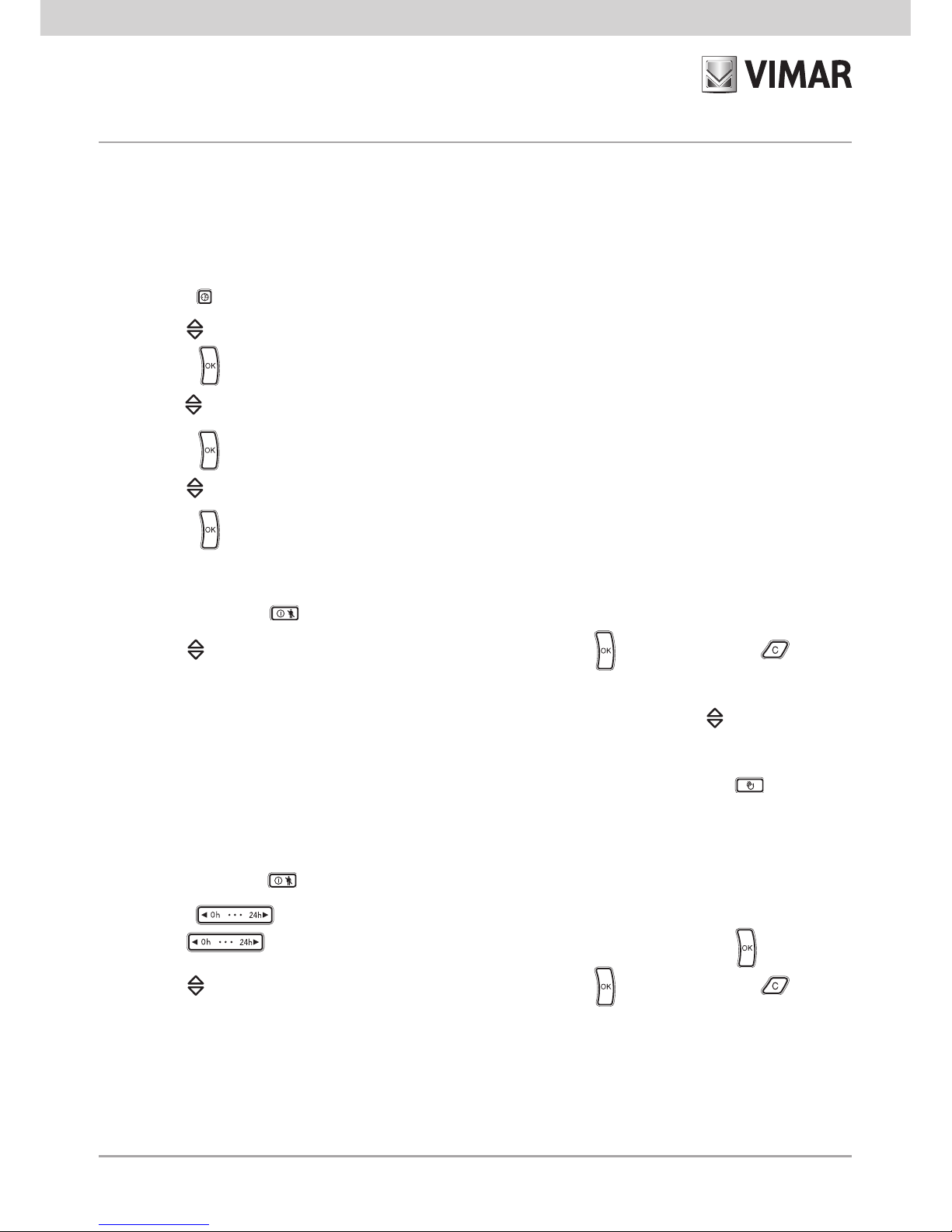
Press button ; the display will only show the arrow at the top to indicate the day and time to set�
- Use button to move the arrow onto the current day�
- Press button to confirm and then move on to setting the time; the two digits indicating the hour start blinking�
- Use button to set the current hour�
- Press button to confirm and move on to setting the minutes; the two digits indicating the minutes start blinking�
- Use button to set the current minutes�
- Press button to confirm and exit; now the date and time have been set�
• Setting the chronothermostat on manual operation
- Repeatedly press button until the display shows the symbol MAn alongside the blinking value of the temperature�
- Use button to select the desired temperature value then press button to confirm or button to cancel
the operation�
- After selecting
“Manual” mode
it is possible to change the set temperature value with button ; this change will be
confirmed automatically after approximately 5 seconds�
Note: From any operating mode it is possible to move onto manual operation
by pressing button �
• Setting the chronothermostat on timed manual operation
- Repeatedly press button until the display shows the symbol MAn alongside the blinking value of the temperature�
- Press button ; the display will show two blinking digits indicating the number of hours (h) to set�
- Use button to select the desired number of hours (from 1 to 99) then press button to confirm�
- Use button to select the desired temperature value then press button to confirm or button to cancel
the operation�
Page 5
3
- After selecting
“Timed Manual” mode
it is possible to change the set temperature value with button ; this change
will be confirmed automatically after approximately 5 seconds�
After setting the chronothermostat in
“Timed Manual” mode
, it is possible to change the duration with button
and then press to confirm�
• Setting the chronothermostat on automatic operation
- Repeatedly press button until the display shows the Auto symbol above the blinking graphic segments that
indicate the daily program schedule�
- Press button to confirm�
In this case it is possible to temporarily go into manual operation, for example if the desired temperature is different
to the programmed temperature, setting the desired value with button and waiting approx� 5 seconds for the
operation to be confirmed�
The new setting will stay active until the next change in the programmed temperature level, after which the stored
program will be restored�
• Switching off the chronothermostat
- Repeatedly press button
until the display shows OFF and, alongside the temperature value, the OFF symbol
blinking
- Press button to confirm�
To switch the chronothermostat back on in one of the available operating modes, repeatedly press button
until the desired one is displayed; finally press button to confirm�
• Timed switching off the chronothermostat
- Repeatedly press button the
OFF button and, alongside the temperature value, the OFF symbol blinking
- Press button ; the display will show two blinking digits indicating the number of hours (h) to set�
- Use button to select the desired number of hours (from 1 to 99) then press button to confirm�
• Setting the chronothermostat on antifreeze operation
- Repeatedly press button
until the display shows Anti and, alongside the set antifreeze temperature value,
the * symbol blinking
- Press button to confirm�
Page 6
4
• Summer/winter selection
This function is used if it is necessary to control not only the heating system, but also the air-conditioning system with
the chronothermostat�
- Press and hold down button ; the display will show SEt together with the (winter) symbol or together with
the (summer) symbol�
- Using button select symbol for the winter season or symbol for the summer season and press button
to confirm�
• Entering the password
The chronothermostat 01913 offers the chance to set a three-digit password (PIN) that enables preventing access to
the configuration data to control the HVAC leaving the user however free to access the following operations:
- setting date and time;
- setting the operating mode (off, timed switch-off, antifreeze, manual, timed manual and automatic);
- setting the seasonal mode (summer/winter)�
If it is necessary to access the configuration menu after entering the password (take care to note it down in the space
set aside at the beginning of this manual), see par� 13�9�9 on page 70�
• Operation in the event of a power outage
In the event of a power outage, the chronothermostat 01913 keeps on working normally thanks to the backup batteries
(when they are completely charged, the batteries ensure chronothermostat operation for approximately 2 hours)�
If there is no supply voltage, when the batteries reach a minimum charge level, the display starts blinking to signal that
the chronothermostat is at the shutdown threshold�
Page 7

5
1. DESCRIPTION
Electronic chronothermostat for ambient temperature control (heating and air-conditioning) with GSM
phone communicator incorporated� Daily/weekly programming, change-over relay output 5(2) A 230 V~,
one supplementary output and one digital input, remote control via SMS, power supply 120-230 V~,
surface mounting, white
2. FIELD OF APPLICATION
The appliance is designed to control room temperature by acting on the control circuit of the burner or
circulation pump (heating) or on the control circuit of the air conditioner (air conditioning), ensuring an
ideal temperature, every day, throughout the week�
The large display shows the room temperature, day, time, system operating status and the daily profile set
for the current program� The GSM communicator, via SMS text messages, enables remote control of the
chronothermostat and output channel; in addition, the device is able to send alarm SMS messages such
as, for example, mains power out/restored, input activation, abnormal temperature, etc�
3. REMOTE CONTROL OF THE CHRONOTHERMOSTAT
Thanks to the integrated GSM communicator, the chronothermostat 01913 allows the user, via simple
SMS messages, remote control of all the temperature control functions of the device�
Besides the functions related to the chronothermostat, the device enables remote control of an
auxiliary
output (to control a generic load) and a digital input (to detect any alarms)�
In addition, the device, via SMS messages, can supply other alarm signals such as no mains power and
temperature less/greater than a preset range (set by the user)�
4. MAIN FUNCTIONS
The chronothermostat, with remote control via simple SMS messages, enables carrying out the following
functions:
• reading and setting the state of all the modes of operation (automatic, manual, etc�) required by the
chronothermostat;
• can activate an alarm on exceeding a maximum temperature threshold set by the user;
• can activate an alarm on exceeding a minimum temperature threshold set by the user;
• reading and setting the state (on or off) of the auxiliary output;
•
management of an alarm event generated by the input, no mains power, exceeding
the upper or lower
temperature threshold, etc; the alarm warning is then notified by sending an SMS message to the set
telephone numbers;
•
reading the state of the input�
Page 8

6
5. IMPORTANT WARNINGS
To ensure optimal operation and use of the GSM chronothermostat 01913, pay attention to the following
points:
•
As regards the type of SIM card, you should make a contract with your preferred telephone
carrier�
If you choose a pay-as-you-go SIM, periodically check the remaining credit and the expiry
date�
CAUTION: The chronothermostat 01913 cannot use SIM cards of the phone carrier 3 ®�
•
Before inserting the SIM card in the chronothermostat, disable the request for the PIN code�
To carry out this operation, insert the SIM in a cell phone and follow the instructions for disabling the
PIN on switching on the phone, given in the instructions manual of the mobile phone being used�
•
Install the chronothermostat in a zone where there is a sufficient level of GSM signal�
To check whether there is sufficient GSM network coverage, please see page 26 of this manual�
3 ® Trademark registered by H3G in Italy�
6. INSTALLATION
The appliance must be installed on a wall at a height of 1�5 m off the floor in a suitable position for correctly
detecting the ambient temperature� It must not be installed in niches, behind doors and curtains or in areas
affected by sources of heat or atmospheric factors�
The appliance must be installed in a position where there is sufficient GSM network coverage�
The base of the appliance has 4 slots for installation straight onto a wall with screws and plugs ø 6 mm
(not supplied) or for installation in recess-mounting enclosures with anchoring by screws with centre
distance 60 mm or 83�5 mm (3-module joined rectangular mounting boxes)�
It should be used in dry, dust-free places at a temperature between 0°C and +40°C�
IMPORTANT: In the electrical system there must be a cut-off device (main switch) that is easily accessible�
Page 9
7
83,5 mm
60 mm
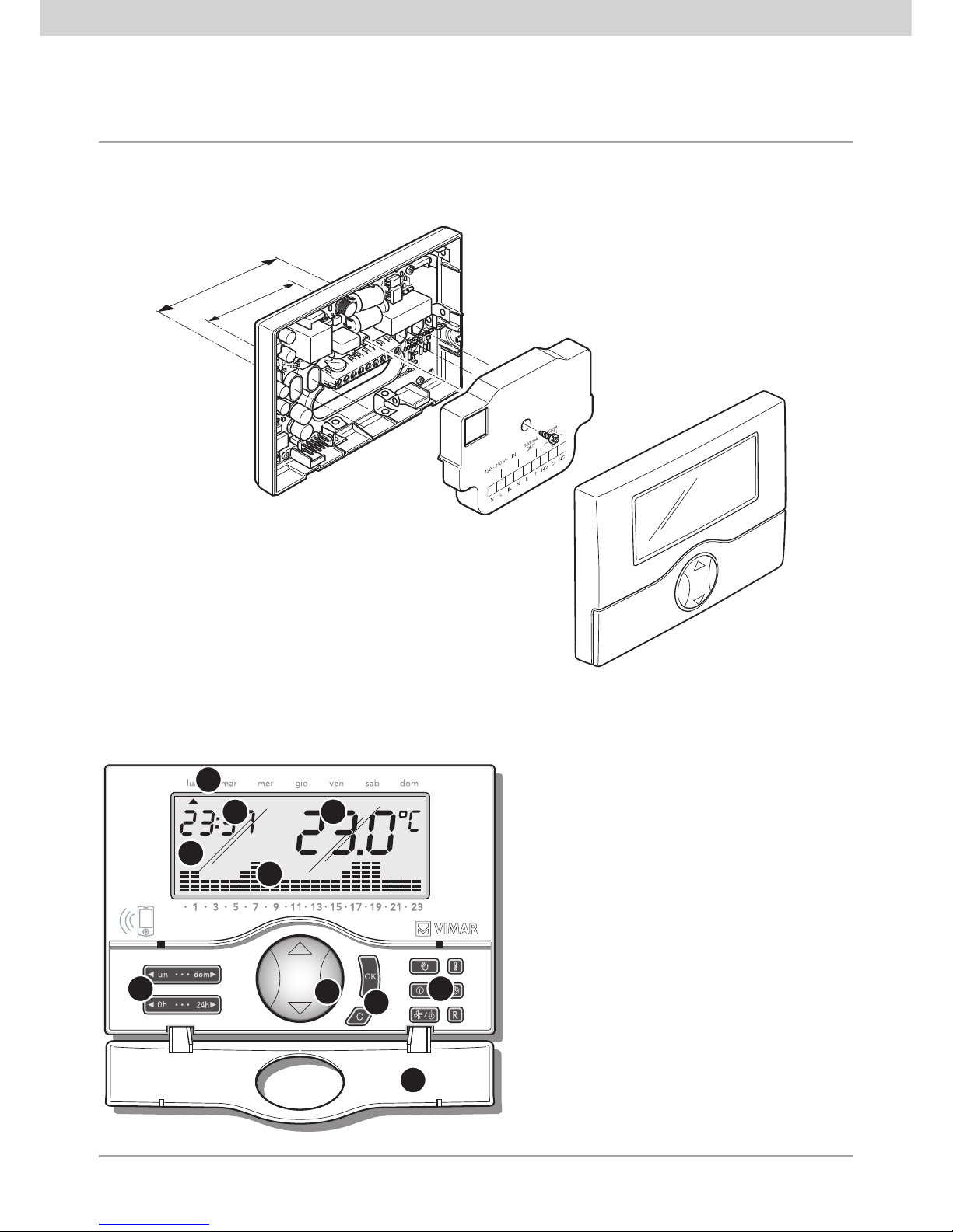
7. FRONT VIEW, CONTROLS AND DISPLAY
1
3
2
4
5
6
7 7
7
8
1. Day of the week�
2. Display�
3. Current time�
4. Room temperature�
5. Daily pattern of the current program�
6. “Mouse” button to control the basic functions�
7. Buttons for programming the functions�
8. Folding front cover�
6.1 Installation operations
Page 10
8
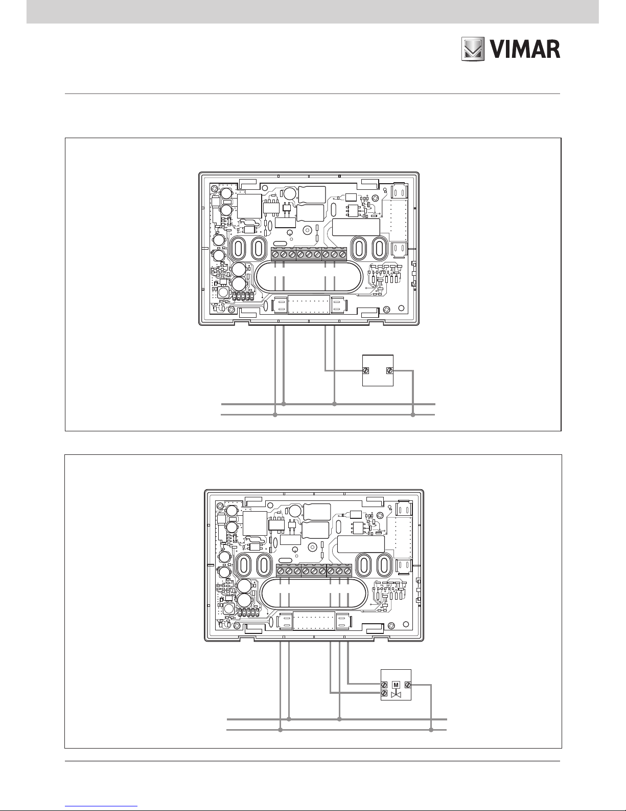
L
N
U1
N L NO NCC
Motorized valves
8. CONNECTIONS
L
N
U1
N L NO NCC
Circulation pumps, burners, solenoid valves
CLOSES
OPENS
Page 11
9
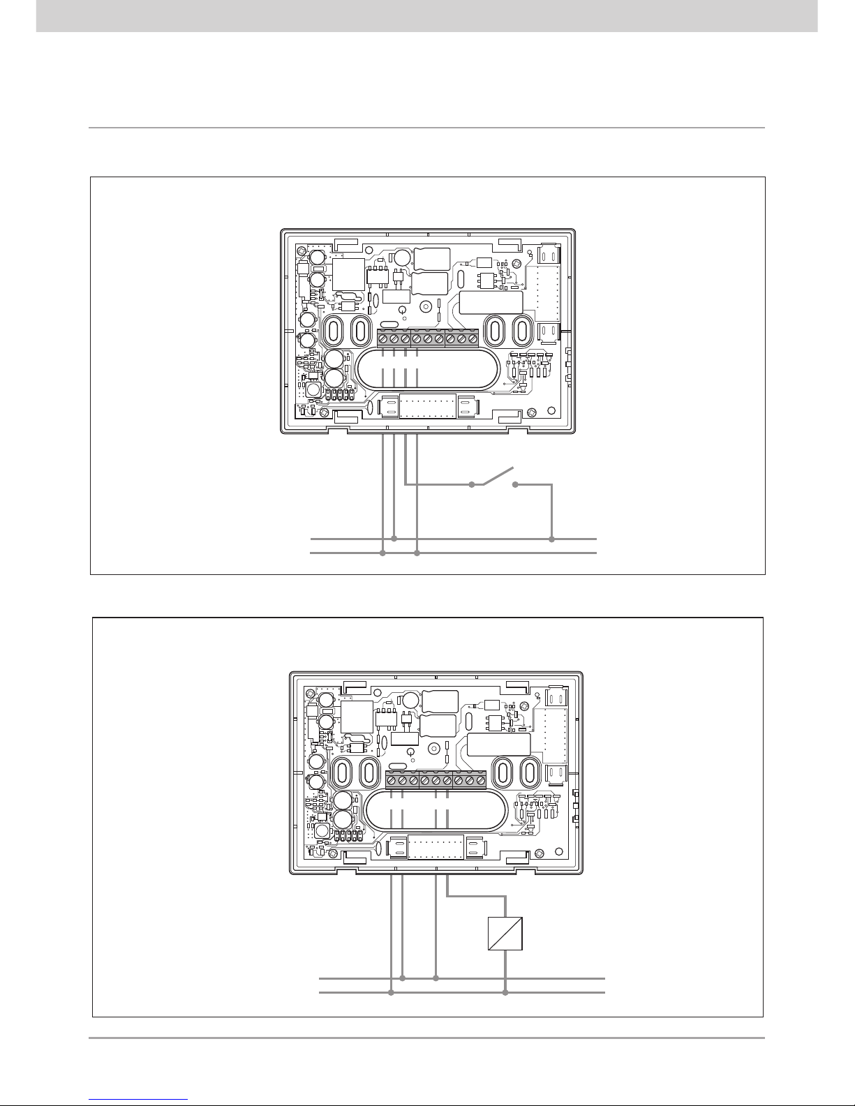
L
N
N L L 1
RELE’
AUSILIARIO
Output to control a generic load
L
N
N L IN N
Digital input for signalling alarms
INPUT
CONTACT
AUXILIARY
RELAY
Page 12
10
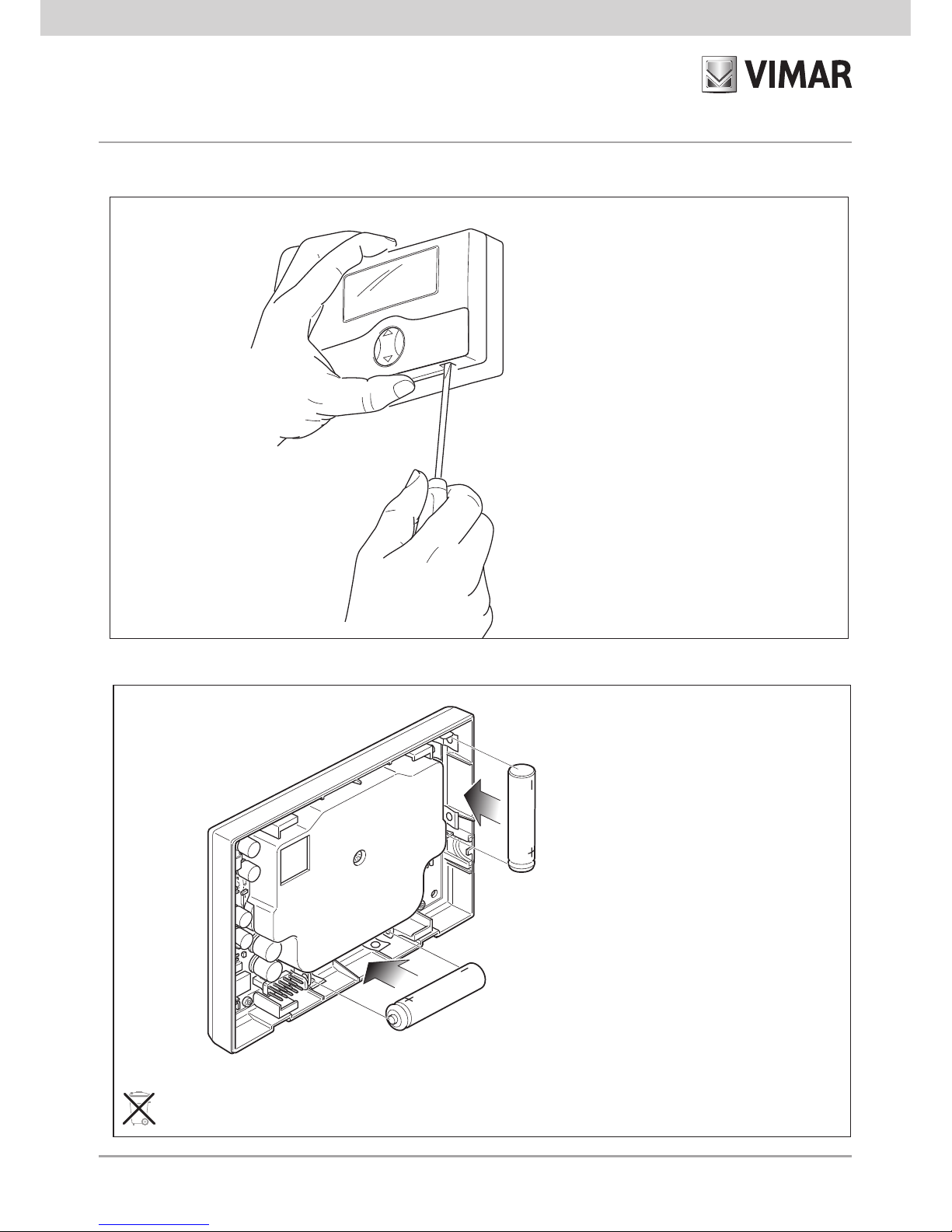
Inserting/removing backup batteries
1.
AAA NiMH 1,2 V
2.
CAUTION!
In case of replacement, dispose of batteries in the
specific differentiated collection bins�
CAUTION!
Before inserting the batteries cut off
the supply voltage with the isolating
device (main switch)�
IMPORTANT!
Never use non-rechargeable
batteries for any reason whatsoever;
this is to avoid the risk of them
exploding�
Page 13

11
Inserting the SIM card
1. Opening 2. Inserting SIM
3. Closing
CAUTION!
Disable the request for the PIN code on
the SIM card being inserted�
Page 14

12
Important warnings for using the SIM card
To ensure correct operation of the SIM card inserted in the GSM chronothermostat 01913, pay attention
to the following points:
•
Contract SIM cards can be used to avoid a lack of credit or expiration of the SIM making the GSM
chronothermostat unusable�
If using prepaid cards, periodically check the remaining credit and the date of expiration�
If necessary, ask the chosen telephone operator for information on how to find out
the remaining credit
and the procedures for topping it up, specifying that the SIM is installed in a device and that the
operations should preferably be carried out without having to take it out of the GSM chronothermostat�
•
Before installing the SIM in the chronothermostat, insert it (as a test) in a GSM cell phone and carry
out the following operations:
- When switching on the telephone, check there is the request to insert the PIN code; if this is enabled
it is necessary to disable this request to insert the PIN�
To do this, please see the instructions manual for the GSM phone used�
- Check the SIM card works properly by sending an SMS text message and afterwards seeing it has
been received; in addition, make a voice call too�
- It is recommended to delete any SMS messages there may be on the SIM card�
•
When using an SMS there can be delays in delivering the messages; this can be caused by special
conditions of the GSM network�
IMPORTANT: The GSM chronothermostat 01913 cannot use SIM cards of the phone carrier 3 ®�
3 ® Trademark registered by H3G in Italy�
Page 15
13
9. KEY FUNCTIONS
• Button .
Enables entering the “Programming” function and selecting the day to program and copying the program
(with“Automatic” mode)�
• Button .
Enables entering the “Programming” function and selecting the time to program (with “Automatic” mode)� Enables
activating and setting the duration in hours of the “Timed Manual” and “Timed Switch-Off” operating modes�
• Button .
Changes selected parameters (e�g�, increase/decrease the temperature)�
• Button .
Confirms the settings�
• Button .
Delete or return to the previous screen�
• Button .
From any mode it enables passing onto “Manual” operation; pressing the button again takes you back to the
previously set operating mode� If the chronothermostat is already working in “Manual” mode, set with button
, pressing this button again takes you into “Automatic” mode�
• Button .
Pressed in sequence, it enables setting the functions of: “Off”, “Timed Switch-Off”, “Antifreeze” (settable only
on heating)
“Manual” e “Automatic”� The
“Timed Switch-Off”
mode can be set by pressing button
after the
“Off” mode has been displayed;
the
“Timed Manual”
mode can be set by pressing button
after the
“Manual” mode has been displayed�
- OFF.
Used to switch off the chronothermostat� The display shows the time and temperature and the output relay remains OFF�
- ANTIFREEZE.
Can only be set on heating, permits setting a minimum temperature level so as to avoid damage to the pipes or
to prevent the temperature from falling under a safety level�
- TIMED SWITCH-OFF.
Used to switch off the chronothermostat for a time that can be set as preferred up to 99 hours�
- MANUAL.
Used to set a constant temperature value in the chronothermostat�
Page 16
14
- TIMED MANUAL.
Used to set the chronothermostat in the
“Manual”
operating mode for a specific period of time (up to 99 hours);
at the end of this time, the device sets the operating mode that had previously been selected�
- AUTOMATIC.
Used to set a time program for temperature control in the chronothermostat�
• Button .
Keeping the button held down enables selecting the chronothermostat operating mode, choosing between
“Heating” and “Air-Conditioning”�
• Button .
Pressed in sequence, it enables setting the values of the “Antifreeze Temperature”, of the “Temperature Levels
T1-T2-T3”, of the “Temperature Differential”, and of the “Temperature Scale”�
- TEMPERATURE LEVELS.
Used to display and/or modify the value of temperature levels T1-T2-T3 for both the heating and air-conditioning
programs�
- TEMPERATURE DIFFERENTIAL.
Used to set the value of the temperature differential� The temperature differential is the difference between the set
temperature and the actual temperature of switching the system on or off� Adjusting the temperature differential to
the type of system avoids continual switching on and off; high inertia systems (for example systems with cast-iron
radiators) need a low temperature differential, while low inertia systems (for example fan heaters) need a higher value�
Example.
If the ambient temperature is set to 20°C and the temperature differential is set to 0�3°C, the system will come on
when the ambient temperature falls to 19�7°C and will go off when it reaches 20�3°C�
- TEMPERATURE SCALE.
Used to set the unit of measurement of the temperature, choosing from between degrees Celsius and degrees
Fahrenheit�
• Button �
Used to set the current time and day of the week� When programming it is used to select the time in steps of 15 minutes�
• Button �
Kept pressed down, all the parameters set on the chronothermostat go into the conditions of first switching
on (resetting the clock, deleting the user programs, return to the default values for the 3 levels of temperature)�
This command does not involve the parameters relating to the GSM part (telephone numbers, parameters of the
digital input, etc�) that are restored to the conditions of first switching on via a specific menu�
Page 17
15
10. PROGRAMMING
Make the electric connections, install the base of the appliance, insert the batteries, insert the SIM card (after previously
disabling the request for the PIN code) and finally connect the chronothermostat to the relevant base�
• Setting date and time
Before beginning to program the chronothermostat, it is advisable to set the current day and time�
- Press button ; the device's display will only show the arrow at the top indicating the day and time to set�
- Use button to move the arrow onto the current day�
- Press button to confirm and then move on to setting the time; the two digits indicating the hour start blinking�
- Use button to set the current hour�
- Press button to confirm and move on to setting the minutes; the two digits indicating the minutes start blinking�
- Use button to set the current minutes�
- Press button to confirm and exit�
• Setting the temperature levels
The temperature levels are those values of temperature that will subsequently be entered in the automatic
program to
be created� The chronothermostat has 3 levels of temperature T1, T2 and T3 besides T antifreeze.
- Press button ; the device's display will show only
SEt
T * (antifreeze) with the reference value blinking�
- Use button to set the desired antifreeze temperature�
- Press button to confirm and pass on to setting the temperature T1; the display will show the reference value
blinking�
- Use button to set the desired temperature T1�
- Press button to confirm and pass on to setting the temperature T2; the display will show the reference value
blinking�
- Use button to set the desired temperature T2�
Page 18
16
- Press button to confirm and pass on to setting the temperature T3; the display will show the reference value
blinking�
- Use button to set the desired temperature T3�
- Press button to confirm; the display will show the dIFF icon and the relevant temperature differential blinking
at 00�2°C�
- Use button to set the desired temperature differential�
- Press button to confirm and pass on to setting the temperature scale; the display will show the current
temperature with the unit of measurement blinking (°C Celsius or °F Fahrenheit)�
- Use button to set the desired unit of measurement�
- Press button to confirm and exit�
• Creating the automatic program
With this procedure you can create the time program that, for each day of the week, regulates the ambient temperature
(heating and air-conditioning) according to the set values T1, T2 and T3�
- Set the “Automatic” operating mode (see page 10)�
- Press button or button to enter the program creation menu; the display will show the
icon PrOG.
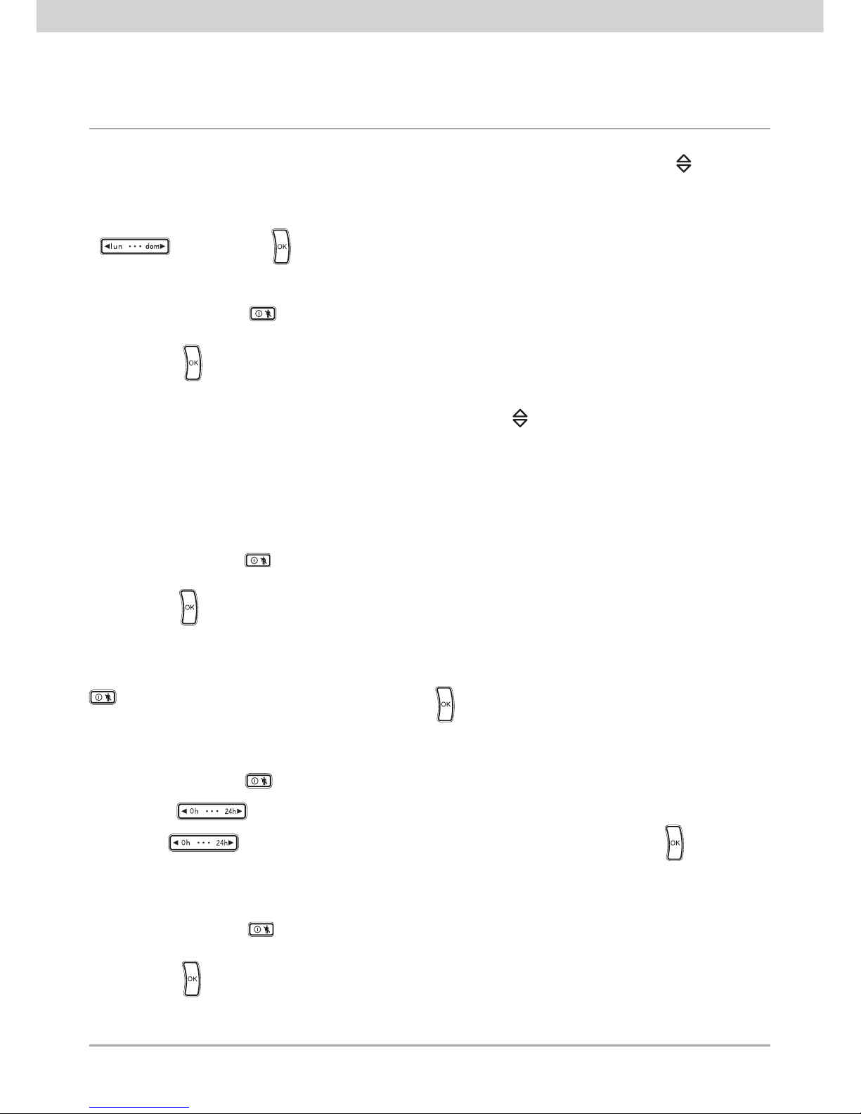
- Press to confirm and access program setting; the display will show the arrow blinking on the day of the week�
- Use button to select the desired day�
When creating a program it is always advised to begin with Monday.
- Use button to select the time; the display will show 00:00 and next to it the set temperature level T1
or T2 or T3�
- Use button to set the value of the desired temperature level; the display will change the histogram according to
the setting�
- Use button to select the following times (from 01.00 to 23:00) and use button to set the value of
the desired temperature level for each one of them�
The display will show the histogram of the selection�
Page 19
17
After setting the temperature value for the time 23:00, press:
• button to confirm the program set for Monday and move on to set the next day;
• button to copy the program of the current day to one of the other days of the week�
After pressing button the display shows:
- a fixed arrow on the day from which to copy the program;
- the COPY icon blinking;
- a blinking arrow on the day to which you want to copy the program�
- Again using button select the day on which you want to copy the program�
- Lastly press button to confirm or button to cancel the operation�
The automatic program creation procedure should then be repeated in the same way for all the days of the week�
Page 20

18
11. OPERATION
Once the chronothermostat has been programmed, it can be put into operation�
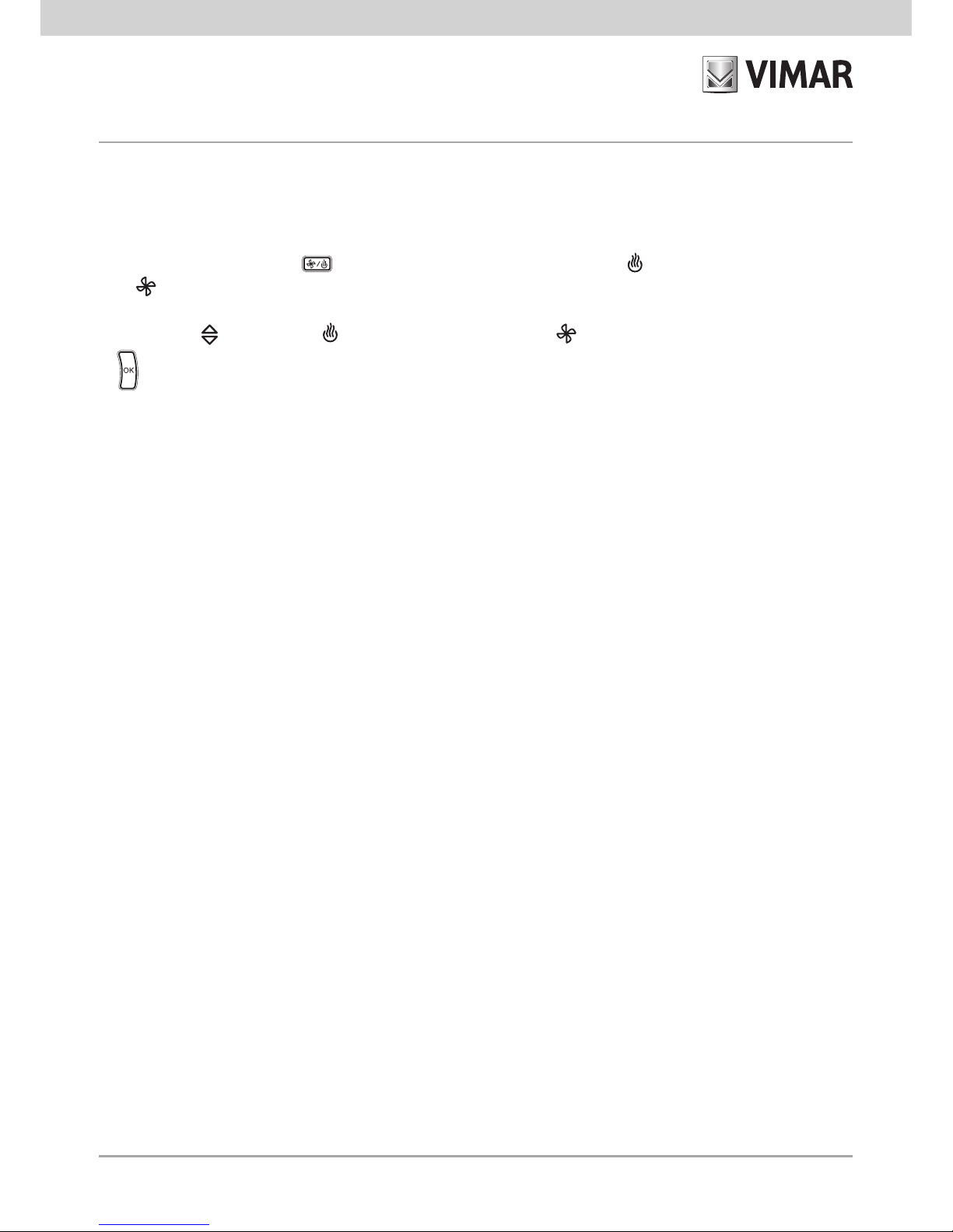
If the relay is activated, the symbol is displayed in the winter (heating) or the symbol in the summer
(air-conditioning)�
• Setting manual operation
- Repeatedly press button until the display shows the symbol MAn alongside the blinking value of the temperature�
- Use button to select the desired temperature value then press button to confirm or button to cancel
the operation� If the setting is not confirmed within approximately 40 seconds, the chronothermostat will return to the
previously set operating mode�
- After selecting
“Manual” mode
it is possible to change the set temperature value with button ; this change will
be confirmed automatically after approximately 5 seconds�
- From any operating mode it is possible to move onto
“Manual” operation
by pressing button � This operation
differs from the above only in the fact that, on pressing button again, you return to the previously set operating
mode�
• Setting timed manual operation
- Repeatedly press button until the display shows the symbol MAn alongside the blinking value of the temperature�
- Press button ; the display will show two blinking digits indicating the number of hours (h) to set�
- Use button to select the desired number of hours (from 1 to 99) then press button to confirm�
The chronothermostat display shows the phase of setting the number of hours with the following indications:
- if the set number of hours is included in the current day, the chronothermostat shows the time when the
“Timed
Manual”
setting ends with two segments blinking on the time printed under the display;
- If the set number of hours exceeds those of the current day (therefore moving on to the next days), the
chronothermostat will show not only the time when the
“Timed Manual”
setting ends (see above), but also the day
when this setting ends; the arrow will be shown blinking on the day printed above the display�
Page 21
19
- Use button to select the desired temperature value then press button to confirm or button to cancel
the operation� If the setting is not confirmed within approximately 40 seconds, the chronothermostat will return to the
previously set operating mode�
- After selecting
“Timed Manual” mode
it is possible to change the set temperature value with button ; this change
will be confirmed automatically after approximately 5 seconds�
After setting the chronothermostat in
“Timed Manual” mode
, it is possible to change the duration with button
and then press to confirm�
The chronothermostat then remains in
Manual
mode for the set length of time at the end of which it returns to the
previously set operating mode�
With button you can return at any time to the previous operating mode�
• Setting automatic operation
- Repeatedly press button until the display shows the Auto symbol above the blinking histogram for the daily
program schedule�
- Press button to confirm�
In this case it is possible to temporarily go into manual mode, for example if the desired temperature is different to
the programmed temperature, selecting the value to set with button and waiting approximately 5 seconds for the
operation to be confirmed�
The new setting will stay active until the next change in the programmed temperature level, after which the stored
program will be restored� During this temporary phase the display shows blinking segments of the hours in which this
temporary mode is on�
To return immediately to the automatic operating mode, press button �
• Off
- Repeatedly press button
until the display shows OFF and, alongside the temperature value, the OFF
symbol blinking
- Press button to confirm� If the setting is not confirmed within approximately 40 seconds, the chronothermostat
will return to the previously set operating mode�
To switch the chronothermostat back on in one of the available operating modes, repeatedly press button until
the one you want is shown�
Page 22
20
• Timed switch-off
- Repeatedly press button
until the display shows OFF and, alongside the temperature value, the OFF symbol
blinking
- Press button ; the display will show two blinking digits indicating the number of hours (h) to set�
- Use button to select the desired number of hours (from 1 to 99) then press button to confirm�
The chronothermostat display shows the phase of setting the number of hours with the following indications:
- if the set number of hours is included in the current day, the chronothermostat shows the time when the
“Timed
Switch-Off”
setting ends with two segments blinking on the time printed under the display;
- If the set number of hours exceeds those of the current day (therefore moving on to the next days), the
chronothermostat will show not only the time when the
“Timed Switch-Off”
setting ends (see above), but also the
day when this setting ends; the arrow will be shown blinking on the day printed above the display�
The chronothermostat then remains in
Off
mode for the set length of time at the end of which it returns to the previously
set operating mode�
• Antifreeze
- Repeatedly press button
until the display shows Anti and, alongside the set antifreeze temperature value,
the * symbol blinking
- Press button to confirm� If the setting is not confirmed within approximately 40 seconds, the chronothermostat
will return to the previously set operating mode�
The Antifreeze value can be selected with the procedure for setting the temperature levels that can be activated by
pressing button �
Page 23
21
• Summer/winter selection
This type of function is only used when, besides the heating system, it is also necessary to control the air-conditioning
system with the chronothermostat�
- Press and hold down button ; the display will show SEt together with the (winter) symbol or together with
the (summer) symbol�
- Using button select symbol for the winter season or symbol for the summer season and press button
to confirm�
In air-conditioning operation (summer), the operations carried out on the chronothermostat are reversed with respect
to those in heating operation (winter)�
• Setting the password
The chronothermostat 01913 offers the chance to set a three-digit password (PIN) that enables preventing access to
the configuration data to control the HVAC leaving the user however free to access the following operations:
- setting date and time;
- setting the seasonal mode (summer/winter);
- setting the operating mode (off, timed switch-off, antifreeze, manual, timed manual and automatic)�
For all the details on setting, changing and using the password, please see par� 13�10�8 on page 73 and par�13�10�9
on page 74 of this manual�
Caution: Take care to note down the number assigned to the password (PIN) in the specific space in the box at the
start of this manual�
Page 24

22
Page 25

23
Managing the chronothermostat 01913
via SMS text messages
Page 26
24
General settings
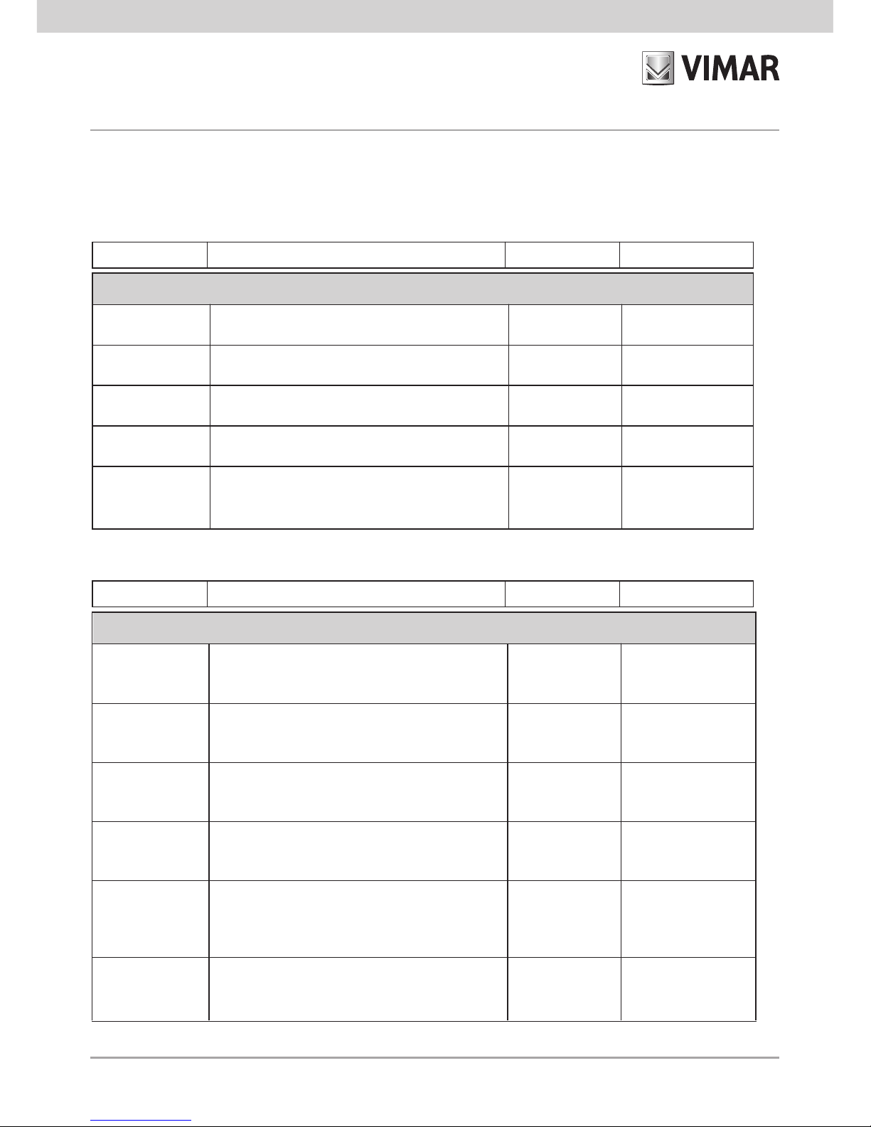
User Code Used to access the GSM chronothermostat functions 1234
min 4 numerical digits
max 10 numerical digits
Phone number
table
Telephone numbers to save for sending SMS alarm
messages�
Blank
max 8 phone numbers of
30 numerical digits each
Redirect noncontrolling SMS
Send non-system SMS texts to a set phone number Disabled
max 1 phone number
can be associated
SMS alarm management settings
Send alarms
Associate the SMS alarm messages with the
telephone numbers to which they are to be sent
No number
max 8 phone numbers
for each alarm
“No Mains Power”
alarm
“No Mains Power” alarm management enabling,
sending SMS alarm message
Enabled
Enabled/Disabled
Upper temperature
threshold exceeded
alarm
Alarm management enabling if the temperature
exceeds the set upper threshold (Tsup)
Disabled Enabled/Disabled
Upper temperature
threshold
Value of the upper temperature threshold (Tsup) 40°C
From 0°C to 40°C
Lower temperature
threshold exceeded
alarm
Alarm management enabling if the temperature is less
than the set lower threshold (Tinf)
Disabled
Enabled/Disabled
12. CONFIGURATION
12.1 DEFAULT VALUES
Parameter Description Default value Permissible values
Parameter Description Default value Permissible values
Address
Text that can be added in an SMS alarm message
to provide information on the user or on the
location of user's dwelling
Blank
Maximum length: 80
characters
SMS language
Language used for the texts and SMS commands
IT
IT, EN, FR, DE, ES
Lower
temperature
threshold
Value of the lower temperature threshold (Tinf)
0°C
From 0°C to 40°C
Page 27

25
Chronothermostat settings
Personalization
“label”
Personal text to identify the chronothermostat in the
SMS commands (C1 always remains valid)
Blank
max 20 alphanumeric
characters
Parameter Description Default value Permissible values
Auxiliary output settings
Personalization
“label”
Personal text to identify the auxiliary output in the SMS
commands (R1 always remains valid)
Blank
max 20 alphanumeric
characters
Mode Auxiliary output operating mode
Two-position
stable
One/Two-position
stable
One-position stable
activation time
Duration of the period of activation in the one-position
stable operating mode
2 s
Parameter Description Default value Permissible values
From 0�1 s to 60 min�
Input settings
Personalization
“label”
Personal text to identify the digital input in SMS
commands (I1 always remains valid) and when
sending the alarm message associated with it
Blank
max 20 alphanumeric
characters
Enabling
management
Enabling management of the input for sending the
SMS alarm message associated with it
Enabled Enabled/Disabled
Operating mode
Interpretation of the state of the input for sending the
alarm message
On -> closed
On -> closed/
On -> open
Activation time
Minimum length of time of continuous presence of the
input signal for the alarm event to be generated
1 s From 0�1 s to 10 min�
Deactivation time
Minimum length of time of continuous absence of the
input signal for the alarm status to be cancelled
1 s From 0�1 s to 10 min�
Parameter Description Default value Permissible values
Note: If configuration parameters with unacceptable values are set, the GSM chronothermostat will
automatically assign the nearest permissible value to the setting or, depending on the type of command,
will display an error message�
Page 28

26
12.2 START-UP PROCEDURE
1� Make sure you have inserted the batteries and made all the necessary connections according to
the required type of installation:
• Power supply terminals�
• Relay terminals for the connection to the boiler�
• Digital input terminals (only if alarm signal detection is required)
• Auxiliary output terminals (only if load control is required)
2�
Make sure you have correctly inserted the SIM card following the instructions given on page 11�
3� Make sure that the base with the connection terminals is securely fastened to the display part�
4� Power up the GSM chronothermostat:
• the display will show all the icons and symbols for a few moments
• after a few moments the icon will start to blink and the chronothermostat will begin the
phase of registering with the GSM mobile phone network
• when the phase of registering with the GSM network successfully ends, the icon will
stop blinking and remain on steady�
If, on the contrary, after a few minutes the icon keeps on blinking, check that the SIM
card is installed correctly or check there is a sufficient level of GSM signal�
The following table gives the possible signals of the icon based on the state of the GSM module
integrated in the chronothermostat�
Icon display status GSM module status
Permanently off
GSM module off
Blinking
SIM card not inserted/No GSM signal/GSM module
not registered on the network
Steady light
GSM module on, registered on the network and
working properly
12.3 GSM signal detection
1� Make sure that the procedures for starting and registering the module on the GSM network have
concluded correctly: in this case the icon is displayed permanently�
2� Access the GSM menu by simultaneously, and for a few seconds, pressing buttons and �
3� Using button scroll through the menus to SIGn tESt and press �
4� The level of the GSM signal is graphically displayed by a histogram at the bottom of the display�
Page 29

27
Note.
• If there is no GSM signal no histogram is shown�
• The level of signal 1 is represented by a horizontal histogram that covers the entire length of the
display�
• The level of signal 2 is represented by a similar histogram to the one used for representing
temperature level T1 (at the bottom right of the display)�
• The level of signal 3 is represented by a similar histogram to the one used for representing
temperature level T2�
• The level of signal 4 is represented by a similar histogram to the one used for representing
temperature level T3�
5� The level of the GSM signal is also represented numerically on the display showing the value of
the parameter CSQ in the first two digits, used for the temperature values�
(The numerical values of the CSQ are defined by the European regulations ETSI 07�07 and can take
on values between 0 and 31, or 99 if the value CSQ cannot be determined)�
As regards remote control via SMS text messages, the GSM chronothermostat 01913 can also be
installed in zones where the level of the GSM signal is equal to 1 (minimum level)�
Vice versa, it is not possible to install the GSM chronothermostat 01913 if there is no GSM signal;
inthis case, it is necessary to place the appliance in a different zone to the one hypothesized�
Without a GSM signal, it is not possible to use the remote control functions and
send SMS
alarm messages, while all the HVAC control functions remain usable as if the device were a normal
chronothermostat�
12.4 PROCEDURE FOR RESTORING THE INITIAL DATA OF THE GSM MODULE
This procedure enables restoring the initial settings of the parameters used for remote control of the
GSM chronothermostat 01913 (see the tables of paragraph 12�1 on page 24)�
To activate the procedure carry out the following:
1� Access the GSM menu by simultaneously, and for a few seconds, pressing buttons and �
2� Using button scroll through the menus to GSM COnF and press �
3� Using button scroll through the menus to GSM rES and press �
4� Using button show YES on the display and press �
5� During this procedure the symbol is displayed rotating�
Page 30

28
Caution: the procedure just described does not affect the settings of the chronothermostat part; these
settings are in fact restored to the initial values with button (see Chap� 9 on page 14 of this manual)�
12.5 USING SMS TEXT MESSAGES
The GSM chronothermostat 01913 can receive SMS messages through which it is possible to
configure, control and request the current status of the device; the form is as follows:
<code>.<content_sms>/<content_sms>/...
where:
• <code> is the user code;
• . is the information separator
• <content_sms> depends on the function you want to actuate
• / is the separator for configurations, commands, multiple requests
If the chronothermostat receives SMS messages with the right user code but with errors in the
content, it will send an error SMS message containing the incorrect text and an indication of the
command (or commands) with the incorrect content�
Example�
Suppose you want to send an SMS message with 4 commands, the first and last of which are not
correct; the
chronothermostat will send an SMS error message with the following form:
GSM-01913 1/1
<SMS received from the GSM Communicator containing the 4 commands>
error on command(s):
1 4
In the case of SMS messages with multiple commands requiring an answer, the chronothermostat is
able to send at most 8 SMS messages in response�
Page 31

29
13. GENERAL CONFIGURATION
13.1 SETTING THE LANGUAGE
The GSM chronothermostat 01913 enables user interaction via SMS messages, available in the
following languages: Italian, English, French, German and Spanish�
The choice of language used for the SMS messages can be made both via SMS and by using the
EasyTool Professional LT software (see the instructions manual supplied with art� 01998�U)�
To set the language, send the following SMS:
<user code>.L.<language code>
where <language code> is the code of the language to set for which there are the following
values:
IT = Italian
EN = English
FR = French
DE = German
ES = Spanish
The procedure does not require any SMS message for confirmation from the chronothermostat�
Example�
If the set user code is the default 1234 and you want to set English for the SMS messages, send the
following SMS:
1234.L.EN
13.1.1 Displaying the current language
It is possible to view the current language used by the chronothermostat both by SMS and with the
EasyTool Professional LT program�
To view the language used, with an SMS message, send the following SMS:
<user code>.?L
to which the communicator will respond with the SMS message:
GSM-01913 1/1
SMS L:<language code>
where <language code> has the meaning illustrated in paragraph 13�1 on page 29�
13.2 USER CODE CONFIGURATION
Remote control of the GSM chronothermostat is protected with a numerical password (User code)
composed of from a minimum of 4 digits to at most 10 numerical digits�
The User code must be entered in all the SMS messages sent to the GSM chronothermostat and
moreover must
be entered also to configure the device with
EasyTool Professional LT software�
Page 32

30
The default User code is 1234 and can be changed both with an SMS message and with the EasyTool
Professional LT program�
To change the User code send an SMS in the form of:
<user code>.COD.<new code>
- If the sent code has more than 10 digits, the GSM chronothermostat will send the following SMS error
message:
GSM-01913 1/1
Error
Code too long
- If the sent code has fewer than 4 digits, the GSM chronothermostat will send the following SMS error
message:
GSM-01913 1/1
Error:
Code too short
- If the sent code has non-numerical characters, the GSM chronothermostat will send the following SMS
error message:
GSM-01913 1/1
Error
Characters not admitted
- If the sent code respects the required form, the GSM chronothermostat will send the following SMS
confirmation message:
GSM-01913 1/1
Entered code:
<code>
Example�
If the set user code is the default 1234 and you want to change it with the new code 6767, the SMS
message to send will be:
1234.COD.6767
The GSM chronothermostat will send the following SMS confirmation message:
GSM-01913 1/1
Entered code:
6767
Note. Restoring the initial data of the GSM module also resets the code to the
default value of 1234)�
Page 33

31
13.3 PHONE NUMBER CONFIGURATION
The GSM chronothermostat 01913 enables sending SMS alarm messages to at most 8 different
telephone numbers; the following points illustrate the functions for managing these numbers�
Read: used to check the phone numbers saved in the 8 positions�
• Send an SMS message in the form of:
<user code>.?NUM
The GSM chronothermostat will send a response SMS message with the list of all the saved phone
numbers in the following form:
GSM-01913 1/1
1:<phone number 1>
2:<phone number 2>
3:<phone number 3>
4:<phone number 4>
5:<phone number 5>
6:<phone number 6>
7:<phone number 7>
8:<phone number 8>
Example� If the set user code is the default 1234 the SMS message to send must be the following:
1234.?NUM
If the numbers saved in the GSM chronothermostat are: 333778899 (position 1) and 333445566
(position 5), the SMS reply message sent by the device will be:
GSM-01913 1/1
1: 333778899
2:
3:
4:
5: 333445566
6:
7:
8:
Enter: used to save a telephone number to one of 8 available positions; the procedure does not
include a confirmation SMS from the GSM chronothermostat�
• Send an SMS message in the form of:
<user code>.NUM<n>.<phone number>
where <n> is the position (from 1 to 8) where you want to enter the telephone number�
Page 34

32
Example� If the set user code is the default and you want to set the number
333778899 in
position 1, send the following SMS:
1234.NUM1.333778899
Delete: used to delete a telephone number saved to one of the 8 positions; the
procedure does
not include a confirmation SMS from the GSM chronothermostat�
• Send an SMS message in the form of:
<user code>.NUM<n>.0 (zero)
where <n> is the position (from 1 to 8) where you want to delete the telephone number�
Example� If the set user code is the default and you want to delete the number
in position
1, send the following SMS:
1234.NUM1.0
13.4 CONFIGURATION FOR REDIRECTING TO A PHONE NUMBER
The GSM chronothermostat can be configured so as to forward non-system SMS messages received
(for example information sent by the telephone carrier), to a specific telephone number� If this function
is enabled, all of the SMS that are received by the GSM chronothermostat and are not recognized as
command SMS messages (that is to say they do not begin with the correct user code) are forwarded
to the set specific telephone number�
To enable this function (called redirecting), send an SMS in the form of:
<user code>.RED.NUM<n>
where <n> is
the position (from 1 to 8) of the telephone number to which you want
to redirect the
messages�
The GSM chronothermostat will send an SMS reply message with the following format:
GSM-01913 1/1
SMS redirection
on number of
index <n>
where index
identifies the position�
Example� If the set user code is the default 1234 and you want to forward all the non-system SMS
messages from the chronothermostat to the telephone number located in position 1, the SMS message
to send will be the following:
1234.RED.NUM1
Page 35

33
The GSM chronothermostat will send the following SMS response message:
GSM-01913 1/1
SMS redirection
on number of
index 1
To turn off this redirecting function, send the following SMS:
<user code>.RED.NUM0 (zero)
The GSM chronothermostat will send the following SMS response message:
GSM-01913 1/1
SMS redirection
Disabled
To query the chronothermostat and view the number on which the redirecting has been set,
send an SMS
in the form of:
<user code>.?RED
If the function is enabled and associated with the phone number saved in position
<n>
, the GSM
chronothermostat will send the following SMS response message:
GSM-01913 1/1
SMS redirection
on number <n>
Vice versa, if the function is not enabled, the GSM chronothermostat will send the following SMS:
GSM-01913 1/1
SMS redirection
Disabled
Page 36

34
13.5 SIM CREDIT REQUEST CONFIGURATION (FOR “PAY-AS-YOU-GO” CONTRACTS)
The GSM chronothermostat 01913, after preliminary configuration via SMS, is able to make remaining
credit requests to the telephone carrier of the SIm card used on the device and redirect them to the
user making the request� This function obviously applies only to pay-as-you-go contracts, where the
operator provides the service of sending SMS messages that give the remaining credit after a call has
been made or an SMS sent to a specific number for such requests�
13.5.1 Setting credit request parameters
The necessary operator parameters for subsequently requesting the remaining credit can be saved on
the communicator after sending the following SMS setting message:
<code>.SIMCREDITSET.<RequestType>.<credit_num>.<sms_string_request_
credit>
<RequestType>: 'C' or 'S'� This is the method specified by the SIMcard carrier for requesting
and receiving remaining credit SMS messages via the number specified in the next field <credit_
num>�
Specifically:
if <RequestType>= C the carrier specifies that receiving remaining credit SMS messages is
dependant on a voice call (C) to the number <credit_num>�
If <RequestType>=S the carrier specifies that receiving remaining credit SMS messages is
dependant on sending an SMS request message to the number <credit_num> containing the
predefined string in the body of the message identified by the field <sms_string_request_
credit>�
<credit_num>: number that the operator requires for requesting the credit and having an answer
via SMS�
<sms_string_request_credit>: entered only for requests via SMS (RequestType = S)�
This setting command does not require an SMS confirmation message�
Examples with the three major Italian operators
While the user code is the default one (1234), the current configuration SMS messages are (remember
that the parameters given below might change in the future at the operator's discretion)�
• TIM SIMcard:
1234.SIMCREDITSET.S.4916.PRE CRE SIN
• VODAFONE SIMcard:
1234.SIMCREDITSET.C.404
• WIND SIMcard:
1234.SIMCREDITSET.C.*123#
Page 37

35
13.5.2 Deleting credit request parameters
The operator parameters set as described in the previous paragraph are deleted after sending the
following SMS:
<code>.SIMCREDITSET.0
13.5.3 Reading credit request parameters
The operator parameters set as described in the previous paragraph are read after sending the
following SMS:
<code>.?SIMCREDITSET
13.5.4 Request for reading the remaining credit
The operator parameters set as described in the previous paragraph are read after sending the
following SMS:
<code>.SIMCREDIT
In the light of this request the GSM chronothermostat 01913, using the parameters set as described
in paragraph 13�5�1, will make a credit request to the telephone operator, whose response will be
passed on via SMS to the applicant within at most approximately 3 minutes�
13.6 CONFIGURING SMS ALARM MESSAGES
The GSM chronothermostat is able to send SMS alarm messages giving users the opportunity to
customize the text� These messages can be customized by sending a configuration SMS message
(as will be described below) or using a personal computer on which the EasyTool Professional LT
software is installed (for all the details please refer to the relevant instructions manual)�
The conditions that cause SMS alarm messages to be sent are the following:
• Input activation alarm
• Alarm for temperature higher than the upper temperature threshold (Tsup)
• Alarm for temperature lower than the lower temperature threshold (Tinf)
• No Mains Power Alarm
• Mains Power Restored Alarm
Page 38

36
The SMS alarm messages are composed, as we will see below, by linking two or three text messages
together depending on the type of alarm message, that is to say:
- the first message is predefined;
- the other messages are optional and can be changed by the user�
The following table shows the parts forming an SMS alarm message�
ALARM TYPE
ALARM TYPE DESCRIPTION
(for input alarm only)
ADDRESS
• predefined
• depending on the type of
alarm event
• cannot be changed by the
user
• optional
• modifiable by the user (via SMS
or PC)
• enables describing the type of alarm
managed from the input
• it is composed of the text label that
can be associated with the input
• optional
• modifiable by the user (via SMS or PC)
• used to add information on the user
or on the location of the dwelling to
the SMS alarm message
13.6.1 Input activation alarm
The GSM chronothermostat can send an SMS alarm message, to at most 8 telephone numbers, if an
alarm condition generated by the input is detected; in particular, the latter can detect whether there
is voltage applied at its terminals�
It is possible to configure the input so that it detects an alarm event passing from a condition of no
voltage at its ends to a condition of voltage at its ends�
This behaviour is obtained by setting the input mode as an “alarm on closing” (that is considering the
input as “normally open”)�
In addition, it is possible to configure the input so that the alarm condition is generated on passing from
a condition of voltage at its ends to a condition of no voltage at its ends� This behaviour is obtained by
setting the input mode as an “alarm on opening” (that is considering the input as “normally closed”)�
The configuration of the input will be described in detail in the following paragraphs�
The SMS alarm message for activation of the input contacts is formed as follows:
“ALARM”
+
alarm type description
(optional)
+
Address Msg.
(optional)
The alarm type description is optional and is composed of the SMS label of the input; with this label,
that can be customized by the user, it is possible to describe the type of input so as to customize the
SMS alarm message (for setting the SMS label please see paragraph 13�6�1�7 on page 39)�
Page 39

37
The Address Msg. is optional and is represented by text that can be customized by the user
who can, for example, summarize the data on the user or on the location of the house where the
chronothermostat is installed (for setting the Address Msg� see paragraph 13�6�1�8 on page 41)�
Note: After setting the Address Msg� it will be entered in all the types of alarm messages�
For managing the input activation alarm, it is necessary to carry out the following configuration
procedures:
•
Setting the input operating mode: alarm on closing (normally o
pen) or alarm on opening (normally
closed)�
• Enabling the alarm on the input�
•
Associating the alarm with the telephone numbers to which the SMS message must be sent�
• Customizing the input SMS label (optional)�
• Customizing the Address Msg� (optional)�
The configuration operations that, via SMS, can be performed on this alarm message are given in the
following points�
13.6.1.1 Enabling or disabling input alarm management
This option, if enabled, allows the chronothermostat to consider the changes in the state of the input
to detect alarm events and warn the user with an SMS message�
If on the contrary this option is disabled, the chronothermostat does not take account of the changes
in the state of the input, thus preventing sending the SMS alarm message�
To enable it, send the following SMS message:
<user code>.I1.ON
Note: No response SMS message is required from the chronothermostat 01913�
Example�
If the set user code is the default 1234 and you want to enable management of the alarm on the input,
send the following SMS:
1234.I1.ON
To disable it, send the following SMS message:
<user code>.I1.OFF
Note: No response SMS message is required from the chronothermostat 01913�
Example�
If the set user code is the default 1234 and you want to disable management of the alarm on the input,
send the following SMS:
1234.I1.OFF
Page 40

38
13.6.1.2 Setting the input activation mode
This setting requires selecting two possible options: activation on closing (equivalent to normally open)
or activation on opening (equivalent to normally closed)�
For activation on closing, send the following SMS message:
<user code>.I1.C
Note: No response SMS message is required from the chronothermostat 01913�
Example�
If the set user code is the default 1234 and you want the alarm to be generated when the input detects
voltage at its ends, send the following SMS:
1234.I1.C
For activation on opening, send the following SMS message:
<user code>.I1.O
Note: No response SMS message is required from the chronothermostat 01913�
Example�
If the set user code is the default 1234 and you want the alarm to be generated when the input detects
no voltage at its ends, send the following SMS:
1234.I1.O
13.6.1.3 Setting the input activation time
This setting enables defining a time interval for activating the input� The chronothermostat detects the
state of activation only when the alarm condition has been maintained for the entire duration of the
set activation time�
For setting the input activation time send the following SMS message:
<user code>.I1.TON.<time>
where <time> is the time of activation, expressed in ms (milliseconds)�
Note: No response SMS message is required from the chronothermostat 01913�
Example�
If the set user code is the default 1234 and you want to set an activation time of 2 s, send the following
SMS:
1234.I1.TON.2000
Page 41

39
13.6.1.4 Setting the input deactivation time
This setting enables defining a time interval for deactivating the input� The chronothermostat detects
the state of deactivation only when the alarm condition has not been detected for at least the entire
duration of the set deactivation time�
For setting the input deactivation time send the following SMS message:
<user code>.I1.TOFF.<time>
where <time> is the time of deactivation, expressed in ms (milliseconds)�
Note: No response SMS message is required from the chronothermostat 01913�
Example�
If the set user code is the default 1234 and you want to set a deactivation time of 2 s, send the
following SMS:
1234.I1.TOFF.2000
13.6.1.5 Associating the alarm with the telephone numbers where the SMS message is to be sent
This setting enables associating the SMS alarm message with up to 8 telephone numbers to which
the message must be sent�
The procedure requires no response from the chronothermostat 01913�
Send the following SMS message:
<user code>.SMSAI.NUM.<n1...n8>
where <n1...n8> is the list of indices of the phone numbers for associating the input alarm
SMS message�
Example�
If the set user code is the default 1234 and you want to associate the SMS input alarm message with
the phone numbers of index 1, 2 and 5, send the following SMS:
1234.SMSAI.NUM.125
To read the associations between all the types of alarm messages and telephone numbers, send the
following SMS:
<user code>.?SMS
The chronothermostat 01913 will send a response SMS message with the list of all the associations
between the phone numbers and the types of SMS alarm messages:
Page 42

40
GSM-01913 1/1
SMSAI: <list of associated phone number indices>
SMSAR: <list of associated phone number indices>
SMSAT1: <list of associated phone number indices>
SMSAT0: <list of associated phone number indices>
Example�
Let us suppose that the set user code is the default 1234 and:
- the input SMS alarm message has been associated with the telephone numbers 1, 2 and 3;
-
the mains power on/off SMS message has been associated with the telephone numbers 1 and 4;
- the higher temperature SMS alarm message has been associated with the telephone number 1;
- the lower temperature SMS alarm message has been associated with the telephone number 1�
On sending the SMS message:
1234.?SMS
The chronothermostat 01913 will send the following SMS response message:
GSM-01913 1/1
SMSAI: 1 2 3
SMSAR: 1 4
SMSAT1: 1
SMSAT0: 1
13.6.1.6
Deleting the association of the alarm with the telephone numbers where the
SMS
message is to be sent
This setting enables deleting the telephone numbers to which the SMS message must be sent�
The procedure requires no response from the chronothermostat 01913�
Send the following SMS message:
<user code>.SMSAI.NUM.0
where 0 is the number zero�
Example�
If the set user code is the default 1234 and you want to delete the association of the SMS input alarm
message with all the phone numbers, send the following SMS:
1234.SMSAI.NUM.0
Page 43

41
13.6.1.7 Customizing the input SMS label
This setting enables defining text to associate with the input so that the SMS alarm message also
provides a description of it�
For setting the input SMS label send the following SMS message:
<user code>.I1.STR.<text>
where <text> is the description to associate with the input (max 20 characters)�
Note: No response SMS message is required from the chronothermostat 01913; do not use the “.”
and “/” characters�
Example�
If the set user code is the default 1234 and you want to associate the “boiler shutdown” description
with the input, send the following SMS:
1234.I1.STR.boiler shutdown
To delete customizing the input SMS label, send the following message:
<user code>.I1.STR.O
where 0 is the number zero�
Note: No response SMS message is required from the chronothermostat 01913�
Example�
If the set user code is the default 1234 and you want to delete the input customization text, send the
following SMS:
1234.I1.STR.0
13.6.1.8 Customizing the Address Msg.
This setting enables defining additional text to associate with the SMS alarm message, so as to
integrate supplementary information (location of the dwelling, etc�)� If set, this text will be added
identically to all the types of alarm message�
To set the Address Msg, send the following SMS:
<user code>.ADDR.<text>
where <text> is the text to enter (max 80 characters)�
Note: No response SMS message is required; do not use the “.” and “/” characters�
Example�
If the set user code is the default 1234 and you want to add information on the user and address to
the alarm messages with the text “Mario Rossi via Verdi 44 VICENZA”, send the following SMS:
1234.ADDR.Mario Rossi via Verdi 44 VICENZA
Page 44

42
For the Address text, send the following SMS
<user code>.ADDR.0
where 0 is the number zero�
Note: No response SMS message is required from the chronothermostat 01913�
Example�
If the set user code is the default 1234 and you want to delete the Address text, send the following
SMS
1234.ADDR.0
To see (for example, if forgotten) the text associated with the Address Msg� send the following SMS
message:
<user code>.?ADDR
The chronothermostat will send an SMS reply message with the set text:
GSM-01913 1/1
ADDR:
<text ADDRESS>
Example�
If the set user code is the default 1234 and the ADDRESS text is “Mario Rossi via Verdi 44 VICENZA”,
on sending the following SMS message:
1234.?ADDR
The chronothermostat will send the following SMS response message:
GSM-01913 1/1
ADDR:
Mario Rossi via Verdi 44 VICENZA
13.6.1.9 Reading input settings
This function allows seeing the settings associated with the input�
The SMS message to send is the following one:
<user code>.?I1
The chronothermostat will send an SMS reply message with the following format:
GSM-01913 1/1
I1
<customized input label>
ENABLED:ON/OFF
ACTIVE:O/C
TON:<time>ms
TOFF:<time>ms
Page 45

43
Example�
If the set user code is the default 1234 and:
- the SMS input label has been set with the text “boiler shutdown”;
- the input alarm has been enabled;
- the set mode is active on closing (normally open);
- the activation and deactivation times are 1s�
On sending the SMS message:
1234.?I1
The chronothermostat 01913 will send the following SMS response message:
GSM-01913 1/1
I1
boiler shutdown
ENABLED: ON
ACTIVE: C
TON: 1000 ms
TOFF: 1000 ms
Page 46

44
The curve represents
the Measured
Temperature
1: Detection of measured temperature alarm greater than Tsup
2: Send SMS alarm message (status: higher temperature alarm)
3: Reset alarm; the device can now detect a new higher temperature alarm�
Tsup - DTA
Tsup + 0,1°C
Tsup
132
13.6.2 Alarm for temperature exceeding the upper temperature threshold value
The GSM chronothermostat can send an SMS alarm message if the temperature
exceeds the
threshold set by the user; this alarm condition is detected when the
measured temperature is greater than
the set upper threshold value (indicated by Tsup) by at least 0�1°C�
After sending the alarm SMS message to the telephone numbers previously set, the chronothermostat
remains in the state of “alarm sent” and, as long as it remains in this state, it will not send any more
higher temperature alarm messages; this condition persists until the measured temperature falls under
the value of:
Tsup - DTA
where DTA is the temperature differential defined for managing the temperature alarms and its value
is the same for managing both the higher and lower temperature alarm�
The following figure outlines what has just been described:
For managing the higher temperature alarm, it is necessary to carry out the following configuration
procedures:
•
Setting the value of the upper temperature threshold�
• Enabling the alarm�
•
Associating the alarm with the telephone numbers to which the SMS message must be sent�
• Changing the value of the temperature differential DTA (optional)�
• Customizing the Address Msg� (optional)�
Note: The DTA has a predefined value that is already set and is optimal for most installation
applications; if you change it, bear in mind that, if there are considerable variations in temperature
around the set threshold value, too low a value assigned to the DTA could cause numerous SMS
alarm messages to be sent out�
Page 47

45
The SMS alarm message is formed in this way:
Temperature alarm!
Tmis: <temperature value>
Tsup: <upper temperature threshold value>
+
Address (option)
The configuration operations that, via SMS, can be performed on this alarm message are given in the
following points�
13.6.2.1 Enabling or disabling higher temperature alarm management
This option, if enabled, allows the chronothermostat to check the measured temperature continuously
in order to detect exceeding the set upper threshold value and warn the user about it with an SMS
message�
To enable it, send the following SMS message:
<user code>.ATEMP.AT1.ON
Note: No response SMS message is required from the chronothermostat 01913�
Example�
If the set user code is the default 1234 and you want to enable management of the alarm for the
temperature exceeding the threshold Tsup, send the following SMS:
1234.ATEMP.AT1.ON
To disable it, send the following SMS message:
<user code>.ATEMP.AT1.OFF
Note: No response SMS message is required from the chronothermostat 01913�
Example�
If the set user code is the default 1234 and you want to disable management of the alarm for the
temperature exceeding the threshold Tsup, send the following SMS:
1234.ATEMP.AT1.OFF
13.6.2.2 Setting the upper temperature threshold
This option is used to set the value of the upper threshold Tsup�
To enable it, send the following SMS message:
<user code>.ATEMP.AT1.XX,X
where XX.X represents the value of Tsup to enter; the possible values to set must lie in the range
between 0°C and 40°C�
Note: No response SMS message is required from the chronothermostat 01913�
Page 48

46
Example 1�
If the set user code is the default 1234 and you want to set the value of Tsup to 35�6
°C, send the
following SMS:
1234.ATEMP.AT1.35,6
Example 2�
If the set user code is the default 1234 and you want to set the value of Tsup to 34
°C, send the
following SMS:
1234.ATEMP.AT1.34
13.6.2.3 Associating the alarm with the telephone numbers where the SMS message is to be sent
This setting enables associating the SMS alarm message with up to 8 telephone numbers to which
the message must be sent�
The procedure requires no response from the chronothermostat 01913�
Send the following SMS message:
<user code>.SMSAT1.NUM.<n1...n8>
where <n1...n8> is the list of indices of the phone numbers for associating the SMS alarm message
for the measured temperature being greater than Tsup�
Example�
If the set user code is the default 1234 and you want to associate the SMS alarm message for the
measured temperature being greater than the threshold value Tsup with the phone numbers of index
1, 2 and 5, send the following SMS:
1234.SMSAT1.NUM.125
To read the associations between all the types of alarm messages and telephone numbers, send the
following SMS:
<user code>.?SMS
The chronothermostat 01913 will send a response SMS message with the list of all the associations
between the phone numbers and the types of SMS alarm messages:
GSM-01913 1/1
SMSAI: <list of associated phone number indices>
SMSAR: <list of associated phone number indices>
SMSAT1: <list of associated phone number indices>
SMSAT0: <list of associated phone number indices>
For the examples, please see paragraph 13�6�1�5 on page 39�
Page 49

47
13.6.2.4
Deleting the association of the alarm with the telephone numbers where the
SMS
message is to be sent
This setting enables deleting the telephone numbers to which the SMS message must be sent�
The procedure requires no response from the chronothermostat 01913�
Send the following SMS message:
<user code>.SMSAT1.NUM.0
where 0 is the number zero�
Example�
If the set user code is the default 1234 and you want to delete the association of the SMS higher
temperature alarm message with all the phone numbers, send the following SMS:
1234.SMSAT1.NUM.0
13.6.2.5 Changing the value of the temperature differential
This function enables changing the value of the temperature differential DTA used for managing the
temperature alarms�
The SMS message to send is the following one:
<user code>.ATEMP.DTA.X,X
where X.X represents the value of DTA to enter; the possible values to set must lie in the range
between 0�1°C and 2°C�
Note: No response SMS message is required from the chronothermostat 01913�
Example�
If the set user code is the default 1234 and you want to set the differential value DTA to 0�4°C, send
the following SMS message:
1234.ATEMP.DTA.0,4
13.5.2.6 Customizing the Address Msg.
See paragraph 13�6�1�8 on page 41�
Page 50

48
13.6.2.7 Reading higher temperature alarm settings
This function allows reading the settings associated with the alarm for the temperature being higher
than the value of Tsup�
The SMS message to send is the following one:
<user code>.?AT1
The chronothermostat will send an SMS reply message with the following format:
GSM-01913 1/1
ENABLED:ON/OFF
AT1:XX,X degrees
DTA:X,X degrees
Example�
If the set user code is the default 1234 and:
- the higher temperature alarm has been enabled;
- the value of the temperature threshold Tsup has been set to 39�2°C;
- the value of the temperature differential DTA has been set to 0�5°C;
On sending the SMS message:
1234.?AT1
The chronothermostat 01913 will send the following SMS response message:
GSM-01913 1/1
ENABLED:ON
AT1:39,2 degrees
DTA:0,5 degrees
Page 51

49
Tinf - 0,1°C
Tinf
132
Tinf + DTA
13.6.3 Alarm for temperature lower than the lower temperature threshold value
The GSM chronothermostat can send an SMS alarm message if the temperature
is lower than the
threshold set by the user; this alarm condition is detected when the measured temperature is less than
the set lower threshold value (indicated by Tinf) by at least 0�1°C�
After sending the alarm SMS message to the telephone numbers previously set, the chronothermostat
remains in the state of “alarm sent” and, as long as it remains in this state, it will not send any more
lower temperature alarm messages; this condition persists until the measured temperature rises above
the value of:
Tinf + DTA
where DTA is the temperature differential defined for managing the temperature alarms and its value
is the same for managing both the lower and higher temperature alarm�
The following figure outlines what has just been described:
1: Detection of measured temperature alarm less than Tinf
2: Send SMS alarm message (status: lower temperature alarm)
3: Reset alarm; the device can now detect a new lower temperature alarm.
For managing the lower temperature alarm, it is necessary to carry out the following configuration
procedures:
•
Setting the value of the lower temperature threshold�
• Enabling the alarm�
•
Associating the alarm with the telephone numbers to which the SMS message must be sent�
• Changing the value of the temperature differential DTA (optional)�
• Customizing the Address Msg� (optional)�
The curve represents
the Measured
Temperature
Page 52

50
Note: The DTA has a predefined value that is already set and is optimal for most installation applications;
if you change it, bear in mind that, if there are considerable variations in temperature around the set
threshold value, too low a value assigned to the DTA could cause numerous SMS alarm messages to
be sent out�
The SMS alarm message is formed in this way:
Temperature alarm!
Tmis: <temperature value>
Tinf: <lower temperature threshold value>
+
Address (option)
Note: The higher and lower temperature alarms are independent of each other; it is therefore possible
to enable only one of them (for example only the lower one), both or none�
The configuration operations that, via SMS, can be performed on this alarm message are given in the
following points�
13.6.3.1 Enabling or disabling lower temperature alarm management
This option, if enabled, allows the chronothermostat to check the measured temperature continuously
in order to detect any decrease with respect to the set lower threshold value and warn the user about
it with an SMS message�
To enable it, send the following SMS message:
<user code>.ATEMP.AT0.ON
Note: No response SMS message is required from the chronothermostat 01913�
Example�
If the set user code is the default 1234 and you want to enable management of the alarm for the
temperature being lower than the threshold Tinf, send the following SMS:
1234.ATEMP.AT0.ON
To disable it, send the following SMS message:
<user code>.ATEMP.AT0.OFF
Note: No response SMS message is required from the chronothermostat 01913�
Example�
If the set user code is the default 1234 and you want to disable management of the alarm for the
temperature being lower than the threshold Tinf, send the following SMS:
1234.ATEMP.AT0.OFF
Page 53

51
13.6.3.2 Setting the lower temperature threshold
This option is used to set the value of the lower threshold Tinf�
To enable it, send the following SMS message:
<user code>.ATEMP.AT0.XX,X
where XX.X represents the value of Tinf to enter; the possible values to set must lie in the range
between 0°C and 40°C�
Note: No response SMS message is required from the chronothermostat 01913�
Example 1�
If the set user code is the default 1234 and you want to set the value of Tinf to 2�6
°C, send the
following SMS:
1234.ATEMP.AT0.2,6
Example 2�
If the set user code is the default 1234 and you want to set the value of Tinf to 3
°C, send the
following SMS:
1234.ATEMP.AT0.3
13.6.3.3 Associating the alarm with the telephone numbers where the SMS message is to be sent
This setting enables associating the SMS alarm message with up to 8 telephone numbers to which
the message must be sent�
The procedure requires no response from the chronothermostat 01913�
Send the following SMS message:
<user code>.SMSAT0.NUM.<n1...n8>
where <n1...n8> is the list of indices of the phone numbers for associating the SMS alarm message
for the measured temperature being less than Tinf�
Example�
If the set user code is the default 1234 and you want to associate the SMS alarm message for the
measured temperature being less than the threshold value Tinf with the phone numbers of index 1, 2
and 5, send the following SMS:
1234.SMSAT0.NUM.125
To read the associations between all the types of alarm messages and telephone numbers, send the
following SMS:
<user code>.?SMS
Page 54

52
The chronothermostat 01913 will send a response SMS message with the list of all the associations
between the phone numbers and the types of SMS alarm messages:
GSM-01913 1/1
SMSAI: <list of associated phone number indices>
SMSAR: <list of associated phone number indices>
SMSAT1: <list of associated phone number indices>
SMSAT0: <list of associated phone number indices>
For the examples, please see paragraph 13�5�1�5 on page 37�
13.6.3.4
Deleting the association of the alarm with the telephone numbers where the
SMS
message is to be sent
This setting enables deleting the telephone numbers to which the SMS message must be sent�
The procedure requires no response from the chronothermostat 01913�
Send the following SMS message:
<user code>.SMSAT0.NUM.0
where 0 is the number zero�
Example�
If the set user code is the default 1234 and you want to delete the association of the SMS lower
temperature alarm message with all the phone numbers, send the following SMS:
1234.SMSAT0.NUM.0
13.6.3.5 Changing the value of the temperature differential
See paragraph 13�5�2�5 on page 47�
13.6.3.6 Customizing the Address Msg.
See paragraph 13�5�1�8 on page 41�
Page 55

53
13.6.3.7 Reading lower temperature alarm settings
This function allows reading the settings associated with the alarm for the temperature being lower
than the value of Tinf�
The SMS message to send is the following one:
<user code>.?AT0
The chronothermostat will send an SMS reply message with the following format:
GSM-01913 1/1
ENABLED:ON/OFF
AT0:XX,X degrees
DTA:X,X degrees
Example�
If the set user code is the default 1234 and:
- the lower temperature alarm has been enabled;
- the value of the temperature threshold Tinf has been set to 4�2°C;
- the value of the temperature differential DTA has been set to 0�5°C;
On sending the SMS message:
1234.?AT0
The chronothermostat 01913 will send the following SMS response message:
GSM-01913 1/1
ENABLED:ON
AT0:4,2 degrees
DTA:0,5 degrees
Page 56

54
13.6.4 Alarm for no mains power/restored mains power
The GSM chronothermostat can send a “No Mains Power” SMS message if there is a power
failure in the dwelling (blackout)�
In addition, at the moment when the mains power is restored, the
chronothermostat can send a “Restored Mains Power” SMS message�
The “No Mains Power” SMS message is formed in this way:
No mains power!
+
Address Msg. (optional)
The “Restored Mains Power” SMS message is formed in this way:
Restored mains power!
+
Address (option)
For managing the two above-mentioned alarms, it is necessary to carry out the following configuration
procedures:
• Enabling the alarm for no mains power/restored mains power�
• Setting the warning times of the alarms for no mains power and/or restored mains power (optional)�
•
Associating the alarm with the telephone numbers to which the SMS alarm message must be sent�
• Customizing the Address Msg� (optional)�
The configuration operations that, via SMS, can be performed on this alarm message are given in the
following points�
13.6.4.1 Enabling or disabling management of the alarm for no mains power/restored mains power
This option, if enabled, allows the chronothermostat to continuously check for mains power, sending
SMS messages to warn of any power failures (blackouts) and returns�
By default, the warning is made after No Mains Power or Restored Mains Power lasting 5 seconds,
indicated by the parameters TOFF and TON (please see the next paragraph 13�6�4�2)�
To enable it, send the following SMS message:
<user code>.AR.ON
Note: No response SMS message is required from the chronothermostat 01913�
Example�
If the set user code is the default 1234 and you want to enable management of the alarm for no mains
power/restored mains power, send the following SMS:
1234.AR.ON
Page 57

55
To disable it, send the following SMS message:
<user code>.AR.OFF
Note: No response SMS message is required from the chronothermostat 01913�
Example
If the set user code is the default 1234 and you want to disable management of the alarm for no mains
power/restored mains power, send the following SMS:
1234.AR.OFF
To read the setting made on the alarm for no mains power/restored mains power, send the following
SMS message:
<user code>.?AR
The chronothermostat 01913 will send an SMS reply message with the following format:
GSM-01913 1/1
AR
ENABLED:ON/OFF
TOFF:5s
TON:5s
Example�
If the set user code is the default 1234 and the alarm for no mains power/restored mains power has
been enabled, on sending the SMS message:
1234.?AR
The chronothermostat 01913 will send the following SMS response message:
GSM-01913 1/1
AR
ENABLED:ON
TOFF:5s
TON:5s
Page 58

56
13.6.4.2 Setting the warning times of the alarms for no/restored mains power
This option allows separately setting the time (in seconds) beyond which the SMS alarm messages
will be sent for “No Mains Power” and “Restored Power Supply”� Obviously, the SMS warning of the
alarm is not sent in cases of momentary variations in power, whether failing or returning, that last less
than the set values of TOFF and TON; this feature can be useful for “filtering” sporadic alarms tied to
momentary mains outages that occur in certain zones of the nation�
As mentioned in the previous paragraph, the parameters identifying these time settings are identified
by the TOFF label (to identify the time in seconds after which the event of “No Mains Power” is notified)
and the TON label (to identify the time in seconds after which the event of “Restored Mains Power” is
notified)� Their default value (after an operation of “Reset GSM parameters”) is 5 sec� and can be set
in a range between 1s and 3600s (1 hour) by means of the SMS messages described below�
To set the time after which the SMS message for No Mains Power is sent out, send the following
message:
<user code>.AR.TOFF.xxxx
where xxxx is the number of seconds after which the “No Mains Power!” SMS message is sent out�
The possible values xxxx to set are between 1 and 3600 (seconds)�
Note: No response SMS message is required from the chronothermostat 01913�
Example�
If the set user code is the default 1234, AR alarm management is enabled (see the preceding par�),
and you want the No Mains Power message to be sent out only after there being no mains power for
at least 10 minutes (600 seconds), send the following SMS message:
1234.AR.TOFF.600
To read the setting for these times it is sufficient to send the AR settings request, with the generic
SMS message:
<user code>.?AR
The reply will give the TOFF and TON parameters as shown in the examples of the previous paragraph
13�6�4�1�
Page 59

57
13.6.4.3 Associating the alarm with the telephone numbers where the SMS message is to be sent
This setting enables associating the SMS alarm message with up to 8 telephone numbers to which
the message must be sent�
The procedure requires no response from the chronothermostat 01913�
Send the following SMS message:
<user code>.SMSAR.NUM.<n1...n8>
where <n1...n8> is the list of indices of the phone numbers for associating the SMS alarm message
for no/restored mains power�
Example�
If the set user code is the default 1234 and you want to associate the SMS alarm message for no/
restored mains power with the phone numbers of index 1, 2 and 5, send the following SMS:
1234.SMSAR.NUM.125
To read the associations between all the types of alarm messages and telephone numbers, send the
following SMS:
<user code>.?SMS
The chronothermostat 01913 will send a response SMS message with the list of all the associations
between the phone numbers and the types of SMS alarm messages:
GSM-01913 1/1
SMSAI: <list of associated phone number indices>
SMSAR: <list of associated phone number indices>
SMSAT1: <list of associated phone number indices>
SMSAT0: <list of associated phone number indices>
For the examples, please see paragraph 13�6�1�5 on page 39�
Page 60

58
13.6.4.4
Deleting the association of the alarm with the telephone numbers where the
SMS
message is to be sent
This setting enables deleting the telephone numbers to which the SMS message must be sent�
The procedure requires no response from the chronothermostat 01913�
Send the following SMS message:
<user code>.SMSAR.NUM.0
where 0 is the number zero�
Example�
If the set user code is the default 1234 and you want to delete the association of the SMS “No Mains
Power” alarm message with all the phone numbers, send the following SMS message:
1234.SMSAR.NUM.0
13.6.4.5 Customizing the Address Msg.
See paragraph 13�6�1�8 on page 41�
Page 61

59
13.7 AUXILIARY OUTPUT MANAGEMENT
The GSM chronothermostat 01913 is equipped with an auxiliary output to control a generic load�
Thisload must be controlled solely via an external auxiliary relay (not supplied)�
The functions that can be used for managing the auxiliary output are given in the following points�
13.7.1 Customizing the SMS label for the auxiliary output
This setting enables defining a text to associate with the auxiliary output; to be used as an alternative
to the default label R1 in the SMS command messages�
For setting the output SMS label send the following SMS message:
<user code>.R1.STR.<text>
where <text> is the description to associate with the input (max 20 characters)�
Note: No response SMS message is required from the chronothermostat 01913; do not use the “.”
and “/” characters�
Example�
If the set user code is the default 1234 and you want to associate the “staircase light” name with the
auxiliary output, send the following SMS message:
1234.R1.STR.staircase light
To delete customizing the auxiliary output SMS label, send the following message:
<user code>.R1.STR.O
where 0 is the number zero�
Note: No response SMS message is required from the chronothermostat 01913�
Example�
If the set user code is the default 1234 and you want to delete the auxiliary output customization text,
send the following SMS message:
1234.R1.STR.0
Page 62

60
13.7.2 Two-position stable mode settings
The operation of the auxiliary output can be configured as two-position stable; this setting is described
in the following table:
COMMAND STATUS DESCRIPTION
ON Auxiliary output on The auxiliary output remains in the on state until the next OFF command
OFF Auxiliary output off The auxiliary output remains in the off state until the next ON command
To set the two-position stable mode, send the following SMS message:
<user code>.R1.BI
Note: No response SMS message is required from the chronothermostat 01913�
Example�
If the set user code is the default 1234 and you want to configure the auxiliary output as two-position
stable, send the following SMS message:
1234.R1.BI
13.7.3 Setting the one-position stable mode and its activation time
The operation of the auxiliary output can be configured as one-position stable and it is possible to also
set the activation time correlated with this mode�
This setting is described in the following table:
COMMAND STATUS DESCRIPTION
ON Auxiliary output on
The auxiliary output remains in the on state for a time equal to the set
activation time
OFF Auxiliary output off The auxiliary output remains in the off state until the next ON command
To set the one-position stable mode, send the following SMS message:
<user code>.R1.MONO.<activation time>
where <activation time> is the value of the activation time, expressed in seconds, that you
want to set; the possible values to set must be in the range between 0�1 s and 3600 s (60 minutes)�
Page 63

61
Note: No response SMS message is required from the chronothermostat 01913�
Example�
If the set user code is the default 1234 and you want to configure the auxiliary output as one-position
stable with an activation time of 0�5 s, send the following SMS message:
1234.R1.MONO.05
13.7.4 Reading auxiliary output configuration
This function enables viewing the configuration assigned to the auxiliary output�
The SMS message to send is the following one:
<user code>.?R1
The chronothermostat will send an SMS reply message with the following format:
GSM-01913 1/1
R1
<auxiliary output customized label>
two-position stable/one-position stable:<time>s
Example�
If the set user code is the default 1234 and:
- the SMS label of the auxiliary output has been set as “staircase lights”;
- the operating mode is configured as one-position stable with an activation time of 2 s�
On sending the SMS message:
1234.?R1
The chronothermostat 01913 will send the following SMS response message:
GSM-01913 1/1
R1
staircase light
ONE-POSITION STABLE:2s
Page 64

62
13.7.5 Activating the auxiliary output
This function is used to activate the auxiliary output and, as a result, the load connected to it via the
external auxiliary output�
The SMS message to send is the following one:
<user code>.R1.ON
The chronothermostat will send an SMS message confirming activation:
GSM-01913 1/1
R1 ON
Example�
If the set user code is the default 1234 and you want to activate the auxiliary output, send the following
SMS message:
1234.R1.ON
The chronothermostat 01913 will send the following SMS response message:
GSM-01913 1/1
R1 ON
13.7.6 Deactivating the auxiliary output
This function is used to deactivate the auxiliary output�
The SMS message to send is the following one:
<user code>.R1.OFF
The chronothermostat will send an SMS message confirming deactivation:
GSM-01913 1/1
R1 OFF
Example�
If the set user code is the default 1234 and you want to deactivate the auxiliary output, send the
following SMS message:
1234.R1.OFF
The chronothermostat 01913 will send the following SMS response message:
GSM-01913 1/1
R1 OFF
Page 65

63
13.7.7 Reading auxiliary output status
This function allows viewing the current status (on or off) of the auxiliary output�
The SMS message to send is the following one:
<user code>.R1.STATO
The chronothermostat will send an SMS reply message with the following format:
GSM-01913 1/1
<label R1>:ON/OFF
Example�
If the set user code is the default 1234 and:
- the SMS label of the auxiliary output has been set as “staircase lights”;
- the auxiliary output is on�
On sending the SMS message:
1234.R1.STATO
The chronothermostat 01913 will send the following SMS response message:
GSM-01913 1/1
staircase light:ON
13.8 REMOTE CONTROL OF THE CHRONOTHERMOSTAT SETTINGS
With simple SMS messages, remote control is possible for all the HVAC settings (operating mode,
programs, temperature levels, etc�) of the GSM chronothermostat�
13.8.1 Customizing the SMS label for the chronothermostat
This setting enables defining a text to associate with the chronothermostat; to be used as an
alternative to the default label C1 in the SMS command messages�
For setting the chronothermostat SMS label send the following SMS message:
<user code>.C1.STR.<text>
where <text> is the description to associate with the input (max 20 characters)�
Note: No response SMS message is required from the chronothermostat 01913; do not use the “.”
and “/” characters�
Example�
If the set user code is the default 1234 and you want to associate the “kitchen” name with the
chronothermostat, send the following SMS message:
1234.C1.STR.kitchen
Page 66

64
To delete customizing the chronothermostat SMS label, send the following message:
<user code>.C1.STR.O
where 0 is the number zero�
Note: No response SMS message is required from the chronothermostat 01913�
Example�
If the set user code is the default 1234 and you want to delete the customization text associated with
the chronothermostat, send the following SMS message:
1234.C1.STR.0
13.8.2 Setting the automatic operation temperature levels
This function is used to set the temperature levels T1, T2, T3 that the chronothermostat uses in the
automatic operation mode�
To set the temperature levels, send the following SMS messages:
<user code>.C1.T1.XX,X to set T1
<user code>.C1.T2.XX,X to set T2
<user code>.C1.T3.XX,X to set T3
where XX,X represents the temperature to set (at most two whole numbers and one decimal)�
The chronothermostat will send an SMS reply message with the following format:
GSM-01913 1/1
Temp T<n> C1:
XX,X degrees
where <n> can take on the values 1, 2 or 3�
Example�
If the set user code is the default 1234 and you want to set the temperature level T2 of the
chronothermostat to 21�5°C, send the following SMS message:
1234.C1.T2.21,5
The chronothermostat 01913 will send the following SMS response message:
GSM-01913 1/1
Temp T2 C1:
21.5 degrees
Page 67

65
13.8.3 Setting the seasonal heating/air-conditioning mode
This function is used to set the chronothermostat operating mode on Heating or Air-Conditioning�
To set the seasonal mode, send the following SMS message:
<user code>.C1.RISC/COND
where RISC represents the Heating mode while COND the Air-Conditioning mode�
The chronothermostat will send an SMS reply message with the following format:
GSM-01913 1/1
C1 AIR-CONDITIONING/HEATING
Example�
If the set user code is the default 1234 and you want to set the chronothermostat on Heating mode,
send the following SMS message:
1234.C1.RISC
The chronothermostat 01913 will send the following SMS response message:
GSM-01913 1/1
C1 HEATING
13.8.4 Switching off the chronothermostat
This function is used to switch off the chronothermostat remotely�
To switch it off, send the following SMS message:
<user code>.C1.OFF
The chronothermostat will send an SMS reply message with the following format:
GSM-01913 1/1
C1 OFF
Example�
If the set user code is the default 1234 and you want to set the OFF mode, send the following SMS
message:
1234.C1.OFF
The chronothermostat 01913 will send the following SMS response message:
GSM-01913 1/1
C1 OFF
Page 68

66
13.8.5 Setting manual operation
This function is used to set the chronothermostat operating mode on MANUAL�
To set this mode, send the following SMS message:
<user code>.C1.MAN.XX,X
where XX,X represents the temperature to set (at most two whole numbers and one decimal)�
The chronothermostat will send an SMS reply message with the following format:
GSM-01913 1/1
C1 MAN
XX,X degrees
Example�
If the set user code is the default 1234 and you want to set manual chronothermostat operation to the
temperature of 22�5°C, send the following SMS message:
1234.C1.MAN.22,5
The chronothermostat 01913 will send the following SMS response message:
GSM-01913 1/1
C1 MAN
22.5 degrees
13.8.6 Setting automatic operation
This function is used to set the chronothermostat operating mode on AUTOMATIC�
To set this mode, send the following SMS message:
<user code>.C1.AUTO
The chronothermostat will send an SMS reply message with the following format:
GSM-01913 1/1
C1 AUTO
Example�
If the set user code is the default 1234 and you want to set the automatic chronothermostat operating
mode, send the following SMS message:
1234.C1.AUTO
The chronothermostat 01913 will send the following SMS response message:
GSM-01913 1/1
C1 AUTO
Page 69

67
13.8.7 Antifreeze setting
This function is used to set the Antifreeze chronothermostat operating mode�
To set this value, send the following SMS message:
<user code>.C1.ANTIGELO.XX,X
where XX,X represents the temperature to set (at most two whole numbers and one decimal)�
The chronothermostat will send an SMS reply message with the following format:
GSM-01913 1/1
C1 ANTIFREEZE
XX,X degrees
Example�
If the set user code is the default 1234 and you want to set the Antifreeze chronothermostat operating
mode at a temperature of 8°C, send the following SMS message:
1234.C1.ANTIGELO.8
The chronothermostat 01913 will send the following SMS response message:
GSM-01913 1/1
C1 ANTIFREEZE
8 degrees
13.8.8 Setting timed switch-off
This function is used to set chronothermostat timed switch-off�
To set this mode, send the following SMS message:
<user code>.C1.OFFTEMP.XX
where XX represents the number of hours (from 1 to 99) in which the chronothermostat must remain
switched off�
The chronothermostat will send an SMS reply message with the following format:
GSM-01913 1/1
C1 TIMED SWITCH-OFF, XX hours
Example�
If the set user code is the default 1234 and you want to set the Timed Switch-Off operating mode for
a period of 22 hours of the chronothermostat, send the following SMS message:
1234.C1.OFFTEMP.22
The chronothermostat 01913 will send the following SMS response message:
GSM-01913 1/1
C1 TIMED SWITCH-OFF, 22 hours
Page 70

68
13.8.9 Setting timed manual
This function is used to set chronothermostat timed manual operation�
To set this mode, send the following SMS message:
<user code>.C1.MANTEMP.XX,X.YY
where XX,X represents the temperature value to set and YY the number of hours (from 1 to 99) in
which the chronothermostat must operate in Manual mode�
The chronothermostat will send an SMS reply message with the following format:
GSM-01913 1/1
C1 MANTEMP
XX,X degrees
YY hours
Example�
If the set user code is the default 1234 and you want to set the timed manual operating mode with a
temperature of 22�5°C for 3 hours, send the following SMS message:
1234.C1.MANTEMP.22,5.03
The chronothermostat 01913 will send the following SMS response message:
GSM-01913 1/1
C1 MANTEMP
22.5 degrees
3 hours
13.8.10 Reading the state of operation of the chronothermostat
This function is used to view the current state of operation of the chronothermostat�
The SMS message to send is the following one:
<user code>.C1.STATO
The chronothermostat will send an SMS reply message with the following format:
GSM-01913 1/1
<label SMS C1>
Meas Temp:XX.X degrees
Set Temp:YY.Y degrees
Mode:<Mode>
Example�
If the set user code is the default 1234 and the chronothermostat is working in Manual mode with a set
temperature of 20°C and a measured ambient temperature of 18�9°C, on sending the SMS message:
1234.C1.STATO
Page 71

69
The chronothermostat 01913 will send the following SMS response message:
GSM-01913 1/1
C1
Meas Temp:18.9 degrees
Set Temp:20 degrees
Mode:MAN
13.9 CHRONOTHERMOSTAT FIRMWARE VERSION REQUEST
This function is used to view the firmware version of the GSM chronothermostat 01913�
The SMS message to send is the following one:
<user code>.INFO
The chronothermostat will send an SMS reply message with the following format:
GSM-01913 1/1
VERSION:<firmware version>
13.10 CHRONOTHERMOSTAT CONTROL VIA GSM MENUS
Some configuration, information request and test functions of the chronothermostat
can be activated
via a menu that is accessed by simultaneously pressing the
and buttons for a few
seconds�
After entering the GSM menu of the chronothermostat 01913, it is possible to scroll through the
list of available items with button , and buttons and to confirm and cancel the choice
respectively�
Each of the menu items is identified with a pair of abbreviations that are displayed alternately on the
portion of display used for viewing the time (top left)�
13.10.1 Viewing the coverage of the GSM signal
For all the details see par� 12�3 on page 26 of this manual�
13.10.2 Resetting the configuration data of the GSM part of the chronothermostat 01913
For all the details see par� 12�4 on page 27 of this manual�
13.10.3 Viewing the state of the input of the chronothermostat 01913
This is a test function that is used to verify the state of the input; to view this, proceed as follows:
- enter the GSM menu (see the beginning of this paragraph);
- using button select the item GSM COnF and press ;
- using button select the item In StAt and press �
Page 72

70
The display (in the temperature field) shows the state of the input (OFF or on)�
13.10.4 Viewing and changing the input configuration parameters
This function is used to set and check the input configuration parameters (see paragraph 13�6�1 on
page 36); to view and edit these configuration parameters proceed as follows:
- enter the GSM menu;
- using button select the item GSM COnF and press ;
- using button select the item In COnF and press ;
The display (in the temperature field) shows the current enabling or disabling setting associated with
the input management (dIS=disabled or Act=enabled)�
With button you can edit this setting while with you return to the previous menu�
Pressing confirms the setting made and you pass on to view t
he setting assigned for generating
the alarm event: ON CLOSED (cLd) or ON OPEN (oPn)�
With button you can change this setting; with you confirm while with you cancel the
change made�
On pressing you pass on to view the setting of the activation time (t On)�
The display (in the temperature field) shows the numerical value of the activation time in seconds
(thisvalue can be set between 0�1s and 10 min; default value 1s)�
With button you can change this value; with you confirm while with you cancel the
change made�
Note: Up to 10 s the increase is 0�1 s, after 10 s the increase is 1 s and after 60 s the increase is 1min�
When setting times of less than one minute the display
shows t On SEC while, for time values longer
than one minute, the abbreviation shown is t On Min�
On pressing
you pass on to view the setting of the activation time (t
OFF)�
The display (in the temperature field) shows the numerical value of the deactivation time in seconds
(this value can be set between 0�1 s and 10 min; default value 1 s)�
With button you can change this value; with you confirm while with you cancel the
change made�
Note: Up to 10 s the increase is 0�1 s, after 10 s the increase is 1 s and after 60 s the increase is
1min�
When setting times of less than one minute the display
shows t OFF SEC while, for time
values longer than one minute, the abbreviation shown is t OFF Min�
Page 73

71
13.10.5 Viewing and changing auxiliary output status
This is a test function used to verify the operation of the auxiliary output and external relay connected
to it�
Important: The auxiliary output MUST be used to control an external auxiliary relay and not to control
the load directly�
Besides viewing the state of the output, this function is also used for activation (Act) and deactivation
(dIs), for the auxiliary output test�
To verify the operation of the auxiliary output, proceed as follows:
- enter the GSM menu;
- using button select the item GSM COnF and press ;
- using button select the item Out StAt and press ;
The display (in the temperature field) shows the current state of the auxiliary output (dIs or ACt)�
Pressing button or exits displaying the state of the auxiliary output while with button you
access the test mode for this output; again using button you select the desired state (the state
flashes)� Finally press to confirm or to cancel the operation�
On accessing the auxiliary output test mode the display shows tEST Out�
13.10.6 Viewing and changing auxiliary output configuration parameters
This function is used to set and check the auxiliary output configuration parameters (see paragraph
13�7 on page 59); to view and edit these configuration parameters proceed as follows:
- enter the GSM menu;
- using button select the item GSM COnF and press ;
- using button select the item Out COnF and press ;
The display (in the temperature field) will show the current setting (BI=two-position stable or
MOn=one-position stable)�
With button you can change this setting; with you confirm while with you cancel the
change made�
Confirmation of the two-position stable setting concludes the procedure for setting the auxiliary output
and you are returned to the main menu�
Confirmation of the one-position stable setting, instead, continues with the display of the out
put
activation time; this value is displayed in the temperature field and is included between 0�1s and 60 min�
Page 74

72
With button you can change this value�
Note: Up to 10 s the increase is 0�1 s, after 10 s the increase is 1 s and after 60 s the increase is
1 min� When setting times of less than one minute the display
shows tMOn SEC, while, for time
values longer than one minute, the abbreviation shown is tMOn
Min�
With button you confirm the setting made while with you cancel the operation�
13.10.7 Enabling temperature alarms, viewing and setting the relevant thresholds and the
temperature differential for managing the temperature alarms
This function is used to enable or disable the temperature alarms (exceeding the threshold values,
etc�) and to set the parameters associated with them; to view and edit these parameters proceed as
follows:
- enter the GSM menu;
- using button select the item GSM COnF and press ;
- using button select the item tEMP ALrt and press ;
The display (in the temperature field) shows the current enabling or disabling setting of the temperature
alarm for exceeding the upper threshold Tsup� (dIS=disabled or ACt=enabled)�
With button you select the desired setting and you confirm with �
On selecting dIS you pass directly to setting the activation of the temperature alarm for exceeding the
lower threshold (Tinf) otherwise you pass on to setting the temperature value of the upper threshold
(Tsup)�
Having done this the device displays the request for setting the temperature alarm for exceeding the
lower temperature threshold (Tinf)�
With button you select the desired state and you confirm with �
If you set dIS you are returned to the main menu otherwise you pass on to setting the temperature
value of the lower threshold (Tinf)�
Subsequently you pass on to setting the temperature differential used for managing the temperature
alarms (DTA)�
The display (in the temperature field) shows the currently set value of the DTA�
With button it is possible to change this value; with button you confirm the setting made while
with you cancel the operation�
Page 75

73
13.10.8 Setting the password (PIN) on the GSM chronothermostat
This function is used to set a three-digit password (also called PIN) to protect the configuration data
of the HVAC control of the chronothermostat 01913�
The password, that at first is disabled (default value 000), is enabled with the procedures described
in this paragraph; once enabled, to access setting some of the configuration parameters of the
chronothermostat, it will be necessary to enter the correct value of this password�
After entering the password you have free access to all the configuration parameters�
If, after entering the password, no operation is carried out on the chronothermostat for at least a
minute, the protection is automatically re-enabled�
When the password is active, it is however possible to access the following functions without any
restriction:
• Setting the day and time�
• Setting the seasonal mode�
• Setting the mode of operation: off, timed switch-off, antifreeze, manual (changing the setpoint), timed
manual (changing the setpoint and the duration), automatic�
Access to all the other settings is made only by entering the correct password�
To enable protection of the chronothermostat with the password it is necessary to set a value other
than 000; vice versa, to disable the protection, it is necessary to assign the PIN with the value 000�
The procedure for setting the password includes an initial phase in which it is required to enter the
current PIN and a successive phase in which it is requested to enter the new PIN�
To set the password, proceed as follows:
1� Access the GSM menu by simultaneously, and for a few seconds, pressing buttons and �
2� With button select the item Pin and press ; the display (in the hours field) will show the
abbreviation Entr Pin and, in the temperature field, the first digit of the password will blink�
3� Using button set the value of the first digit then press to confirm; the display (in the hours
field) will show Entr Pin and, in the temperature field, the second digit of the password will blink�
4� Using button set the value of the second digit then press to confirm; the display (in the
hours field) will show Entr Pin and, in the temperature field, the third digit of the password will blink�
5� Using button set the value of the third digit then press to confirm; the display (in the hours
field) will show nEw Pin and, in the temperature field, the first digit of the new password will blink�
Page 76

74
6� Using button set the value of the first digit of the new password then press to confirm;
the display (in the hours field) will show nEw Pin and, in the temperature field, the second digit of the
password will blink�
7� Using button s
et the value of the second digit of the new password then pre
ss to confirm;
the display (in the hours field) will show nEw Pin and, in the temperature field, the third digit of the
password will blink�
8� Using button set the value of the third digit of the new password then press to confirm�
13.10.9 Access to the GSM chronothermostat when the password is enabled
When access to the chronothermostat is protected by the password, to access the configuration
functions it is necessary to enter the correct PIN�
The display, in the hours field, will show the request to enter the PIN with the word Pin and, in the
temperature field, the first digit of the password to be entered will blink�
Using button set the value of the first digit then press to confirm; the second digit of the
password will blink on the display�
Using button set the value of the second digit then press to confirm; the third digit of the
password will blink on the display�
Using button set the value of the third digit then press to confirm�
13.10.10 Viewing the firmware version of the GSM chronothermostat
This function is used to view the version of the firmware in the chronothermostat 01913� To view this
version, proceed as follows:
- Access the GSM menu by simultaneously, and for a few seconds, pressing buttons and �
- Using button select the item SYSt InFO and press to confirm�
- Using button select the item FIrM SELF and press to confirm�
The display, in the temperature field, will show the version of the firmware in the GSM chronothermostat
01913�
Page 77

75
13.11
GSM CHRONOTHERMOSTAT CONTROL VIA EASYTOOL PROFESSIONAL LT
SOFTWARE
The GSM chronothermostat 01913 can also be managed with the EasyTool Professional LT software
by connecting the device to a personal computer via the interface 01998�U�
The main functions that the application enables to carry out are the following:
• User code management�
• Reading the SW version of the GSM chronothermostat�
• Managing the telephone numbers for sending the alarm messages�
• Managing the associations between the SMS alarm messages and the telephone numbers�
• Managing the language used in the SMS messages: Italian, English, French, German and Spanish�
• Managing the chronothermostat operating mode: Automatic, Manual, Timed Manual, Antifreeze,
Offand Timed Switch-Off�
• Reading and modifying the time programs for automatic operation�
• Managing the auxiliary output configuration parameters�
• Managing the input configuration parameters�
• Auxiliary output test: reading its state and setting its state�
• Input test: reading its state�
• Managing the “address” text�
• Managing the chronothermostat SMS label (default setting C1)�
• Managing the auxiliary output SMS label (default setting R1)�
• Managing the input SMS label (default setting I1)�
• Managing temperature levels: Tantifreeze, T1, T2 and T3�
•
Managing the seasonal mode: heating or air-conditioning�
•
Updating the firmware of the chronothermostat 01913�
Note:
For all the details concerning the procedures for managing the GSM chronothermostat 01913 with
the EasyTool Professional LT program, please see the manual equipping art� 01998�U�
Page 78

76
13.11.1 Connections for managing the chronothermostat via EasyTool Professional LT.
1� Detach the top of the chronothermostat from its base�
2� Arrange the housing for the flat cable in the base of the chronothermostat�
Page 79

77
3� Connect the interface 01998�U to the top of the chronothermostat with the flat cable and the
specific connector�
Page 80

78
3� Reconnect the top of the chronothermostat to its base�
IMPORTANT: To manage the GSM chronothermostat 01913 with the EasyTool Professional LT
software, it is necessary for the device to be powered from the mains�
For all the details concerning the procedures for managing the GSM chronothermostat 01913 with the
EasyTool Professional LT program, please see the manual equipping art� 01998�U�
Page 81

79
14. MAIN CHARACTERISTICS
• Power supply: 120 - 230 V~, 50-60 Hz
• 2 AAA NiMH 1,2 V rechargeable batteries for the power supply in case of black out; the chronothermostat 01913,
with no mains power and starting from the condition of batteries charged, remains completely functional (that is with
the GSM module active) for approximately two hours�
• Relay output with clean change-over contact: 5(2) A 250 V ~
• 1 digital input 120 - 230 V~ (signalling alarms such as, for example, boiler shutdown);
• 1 output 100 mA 120 - 230 V~ to control an auxiliary relay;
• Integrated GSM communicator with internal antenna that, via SMS messages, enables:
- Managing chronothermostat operation;
- Configuring the chronothermostat;
- Querying the chronothermostat to know its status;
- Switching the supplementary relay output on and off and querying its status;
- Querying the state of the digital input;
- Redirecting non-system SMS messages�
• Warning of alarms via SMS that can be associated with the digital input; sending up to 8 different phone numbers
• Connection with interface 01998�U for programming with a PC using the EasyTool Professional LT software
• Installation:
- surface-mounting with plugs;
- on flush-mounting boxes V71303;
- on flush-mounting boxes with distance between centres 60 mm�
• Time temperature setting
• 1 program for heating and 1 for air-conditioning
• 4 programmable temperature levels for heating and 4 for air-conditioning (T1, T2, T3 and Tantifreeze)
• Operating mode:
- Manual;
- Timed manual;
- Automatic;
- Off;
- Timed switch-off�
• Displayed temperature update: every 20 s
• Room temperature display: 0°C +40°C
• Reading resolution: 0�1°C
• Settings resolution: 0�1°C
• Reading accuracy:
- ≤ ±0�5°C between +15°C and +30°C
- ≤ ±0�8°C at the extremes
• Temperature differential: adjustable from 0�1°C to 1°C
Page 82

80
• Adjustment range:
- +4°C - +15°C on antifreeze
- +5°C - +35°C on heating or air-conditioning
• Clock error: ≤ 1 s a day
• Protection class: IP30
• Appliances of class II:
• Number of manual cycles: 3,000
• Number of automatic cycles: 100,000
• Type of contact opening: micro-disconnection
• Type of action: 1CU
• Tracking index: PTI175
• State of pollution: 2 (normal)
• Rated pulse voltage: 4000 V
• Ambient temperature during transport: -25°C +60°C
• Operating temperature: T40 (0°C +40°C)
• ErP classification (Reg� EU 811/2013): class I, contribution 1%
• Software class: A
• Phone communication: GSM-GPRS, E-GSM 900, 1800 MHz GPRS module class 10
• Built-in internal antenna
15. INSTALLATION RULES
Installation should be carried out in compliance with the current regulations regarding the installation of electrical
systems in the country where the products are installed�
16. CONFORMITY
R&TTE directive
Standards EN 60730-1, EN 60730-2-7, EN 60730-2-9, EN 301 489-1, EN 301 489-7, EN 301 511
Vimar reserves the right to change the stated features of the products at any time and without notice
Page 83

81
Page 84

01913IEN 03 1512
VIMAR - Marostica - Italy
Viale Vicenza, 14 - 36063 Marostica VI - Italy
Tel� +39 0424 488 600 - Fax (Italia) +39 0424 488 188
Fax (Export) +39 0424 488 709
www�vimar�com
 Loading...