

Page 1
JSC „VILTRUS“
K. Donelaičio str. 62, LT-44248 Kaunas, Lithuania
Mobile: +370 699 53998
Email: [email protected]
http://www.viltrus.com
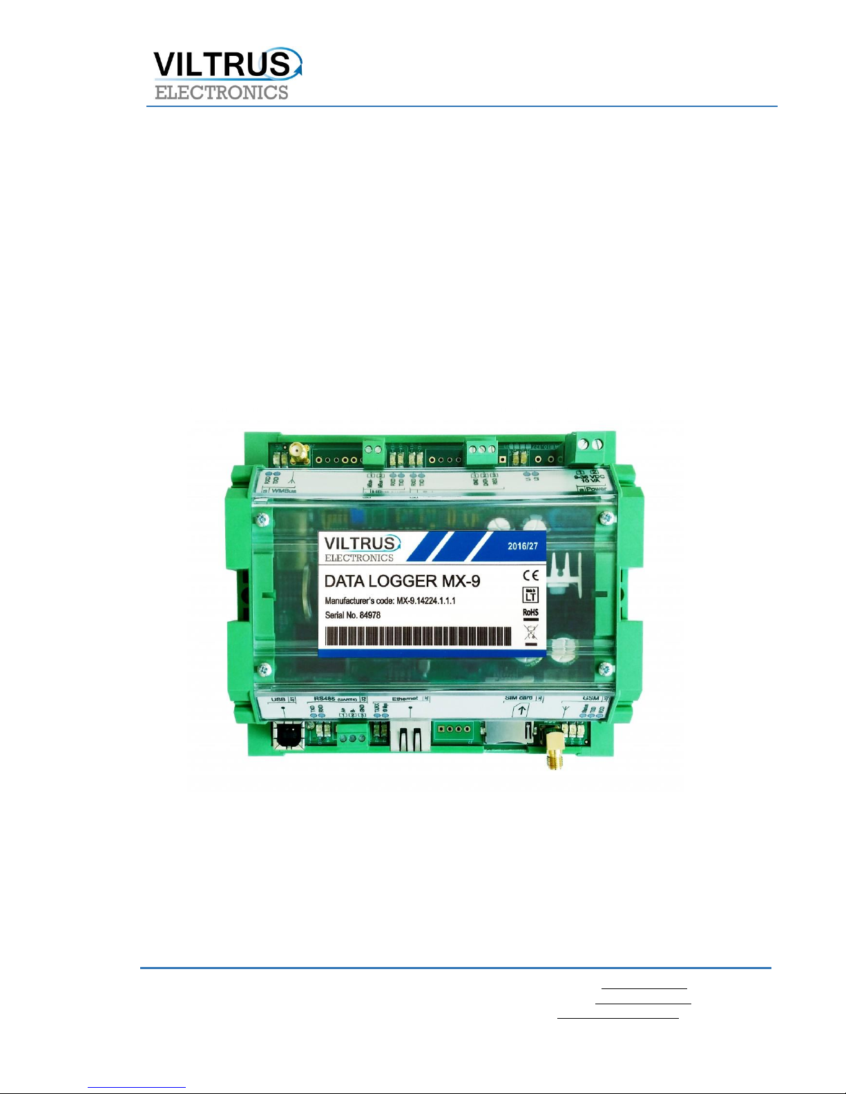
MX-9 is Wireless M-Bus Data logger / Gateway
(433/868 MHz OMS)
User Manual
Page 2

2
Content
1 INTRODUCTION 4
2 SETTING UP CONNECTION TO THE DEVICE 4
2.1 USB connection 5
2.2 ETHERNET Connection 5
2.3 GPRS connection 6
2.4 MX-9 connection diagrams 7
3 "START" TAB 7
3.1 MX-9 Basic Information 7
3.2 Configuration files 8
3.3 Status indicators 9
4 “DISCRETE INPUTS” TAB 10
5 “COMMUNICATION” TAB 11
5.1 Communication > Ethernet 11
5.2 Communication > GPRS 12
5.3 Communication > UARTs 15
5.4 Communication > Virtual interfaces 15
5.5 Communication > Data transfer 17
5.6 Communication > FTP Server 20
5.7 Communication > MQTT Subscriber 21
5.8 Communication > Routing 22
5.9 Communication > Connected devices 25
5.9.1 M-Bus devices 25
5.9.2 Wireless M-Bus devices 33
5.10 Communication > Modbus devices 37
5.11 Communication > Modbus register grouping 39
6 "ARCHIVES" TAB 41
7 "LIMITS VERIFICATION" TAB 42
8 "ALERTS" TAB / 43
Page 3

3
8.1 SMS Alerts on Limit verification 43
8.2 Email Alerts on Limit verification 43
8.3 MQTT Alerts on Limit verification 44
9 "TIME PARAMETERS" TAB 45
10 ABBREVIATIONS AND EXPLANATIONS 46
11 SAFETY INSTRUCTIONS 47
12 TECHNICAL DATA 48
12.1 Communication interfaces 48
12.2 Galvanic insulation 48
12.3 Indication 48
12.4 Power supply 49
12.5 Construction 4949
12.6 Climate conditions 49
12.7 Safety parameters 49
12.8 Other parameters 49
Page 4
4
1 Introduction
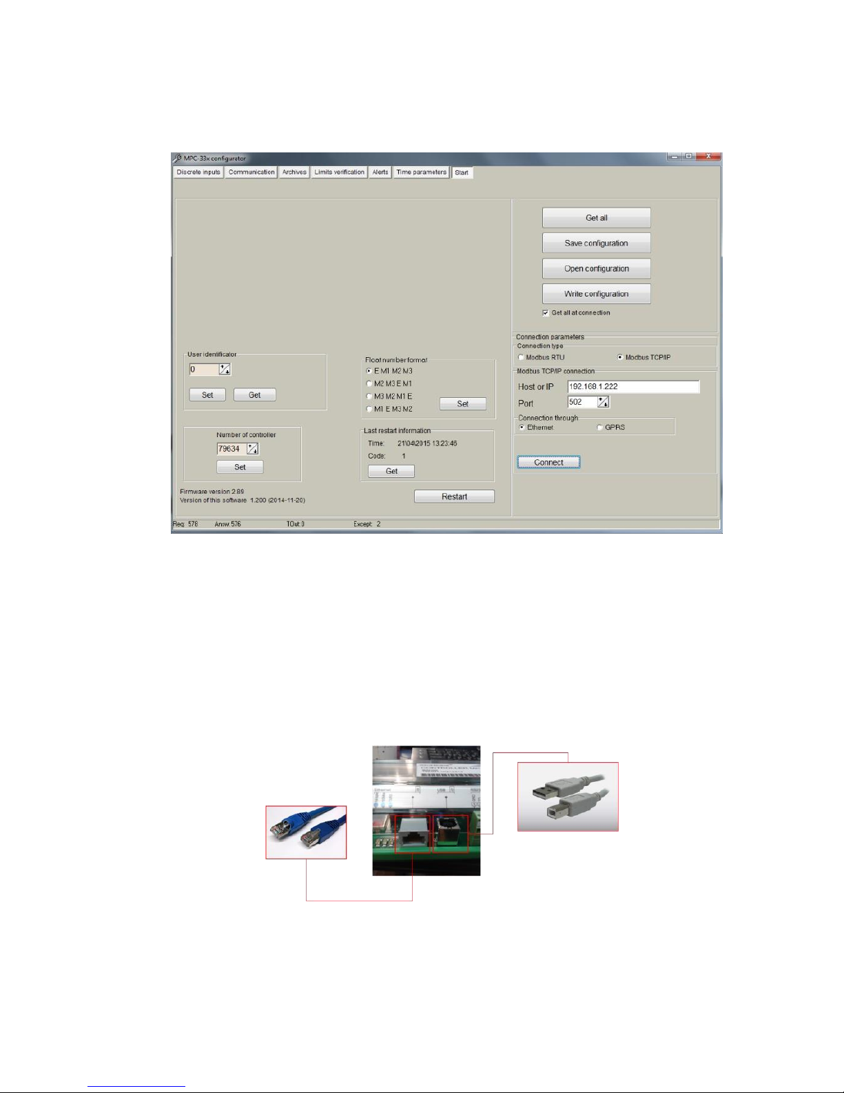
This Manual will show you how to configure datalogger by using the MX-9 configurator software.
Figure 1. MX-9 Configurator
2 Setting up connection to the device
In order to configure the controller, user must connect its PC to the device by using any of
the following interfaces:
1. USB port
2. ETHERNET interface
3. Through a GPRS connection (only accessible after configuring GPRS APN, user
and password inside the controller)
Figure 2. MX-9 connection interfaces
NOTE: Not all the models support above interfaces. Check your ordering code first.
Page 5
5
2.1 USB connection
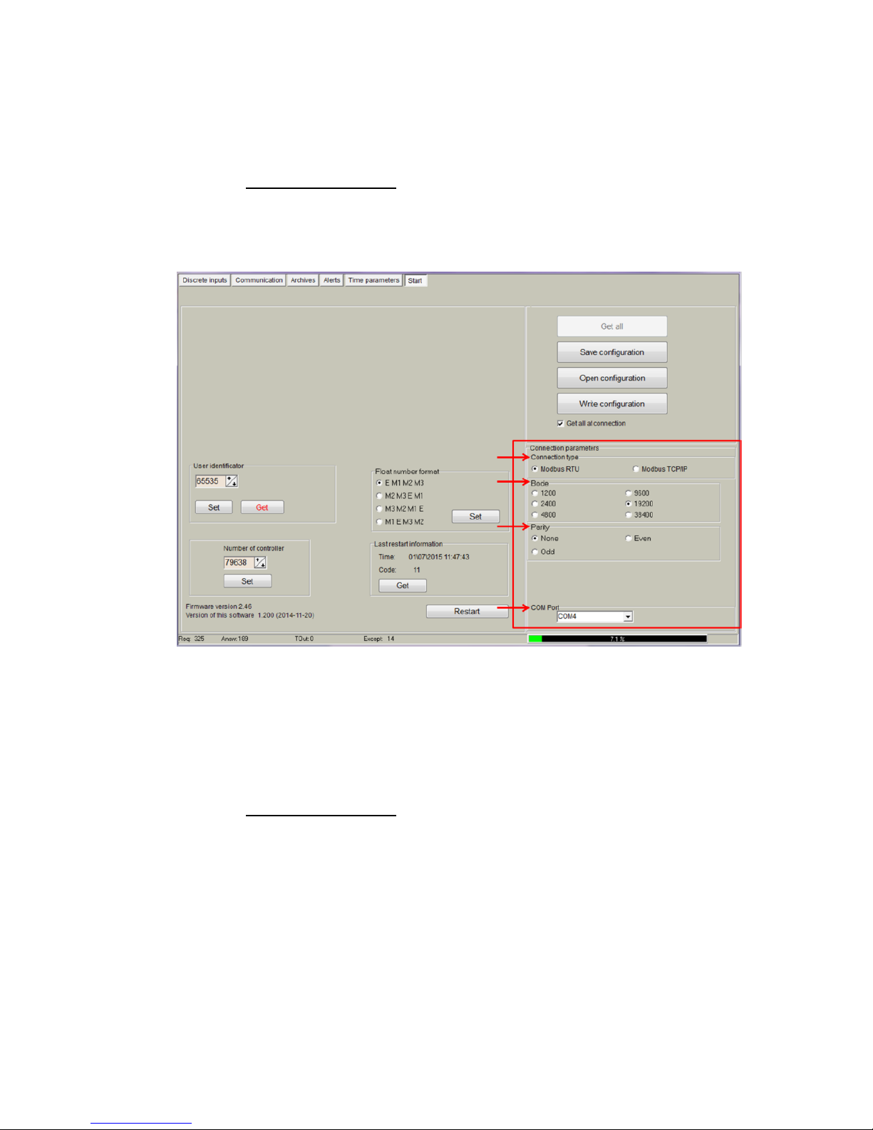
Steps to be followed:
- Connect an USB cable class B to the correspondent port
- Open MX-9 Configuration Tool
- Set up "Connection Parameters" frame
- Select "ModBus RTU" option under "Connection type"
- Configure “Bode” and “Parity” parameters; default values are:"19200" , "none"
- Select COM port number asigned by your PC to the USB port
- Click on “Get all” to establish connection with controller.
Figure 3. USB connection set up
2.2 ETHERNET Connection
Steps to be followed:
- Connect a RJ45 Ethernet cable to the correspondent port.
- Open MX-9 Configuration Tool
- Set up "Connection Parameters" frame
- Select "ModBus TCP/IP" option under "Connection type"
- Add controller IP address and TCP port in "Host or IP" and “Port” text boxes respectively
- Select “Ethernet” option under “Connection through”
- Click on “Connect” to establish connection with controller.
Page 6
6
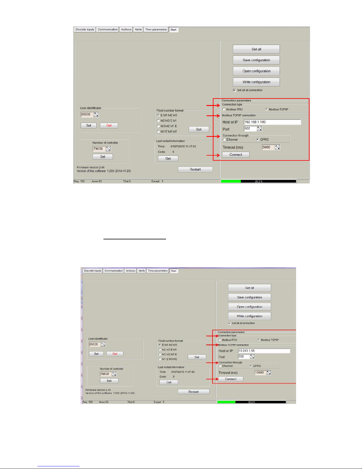
Figure 4. Ethernet connection set up
2.3 GPRS connection
Steps to be followed:
- Check GPRS antenna is properly connected to the device.
- Open MX-9 Configuration Tool
- Set up "Connection Parameters" frame
- Select "ModBus TCP/IP" option under "Connection type"
- Add controller IP address and TCP port in "Host or IP" and “Port” text boxes, respectively
- Select “GPRS” option under “Connection through”
- Click on “Connect” to establish connection with controller.
Figure 6. GPRS connection set up
Page 7
7
2.4 MX-9 connection diagrams
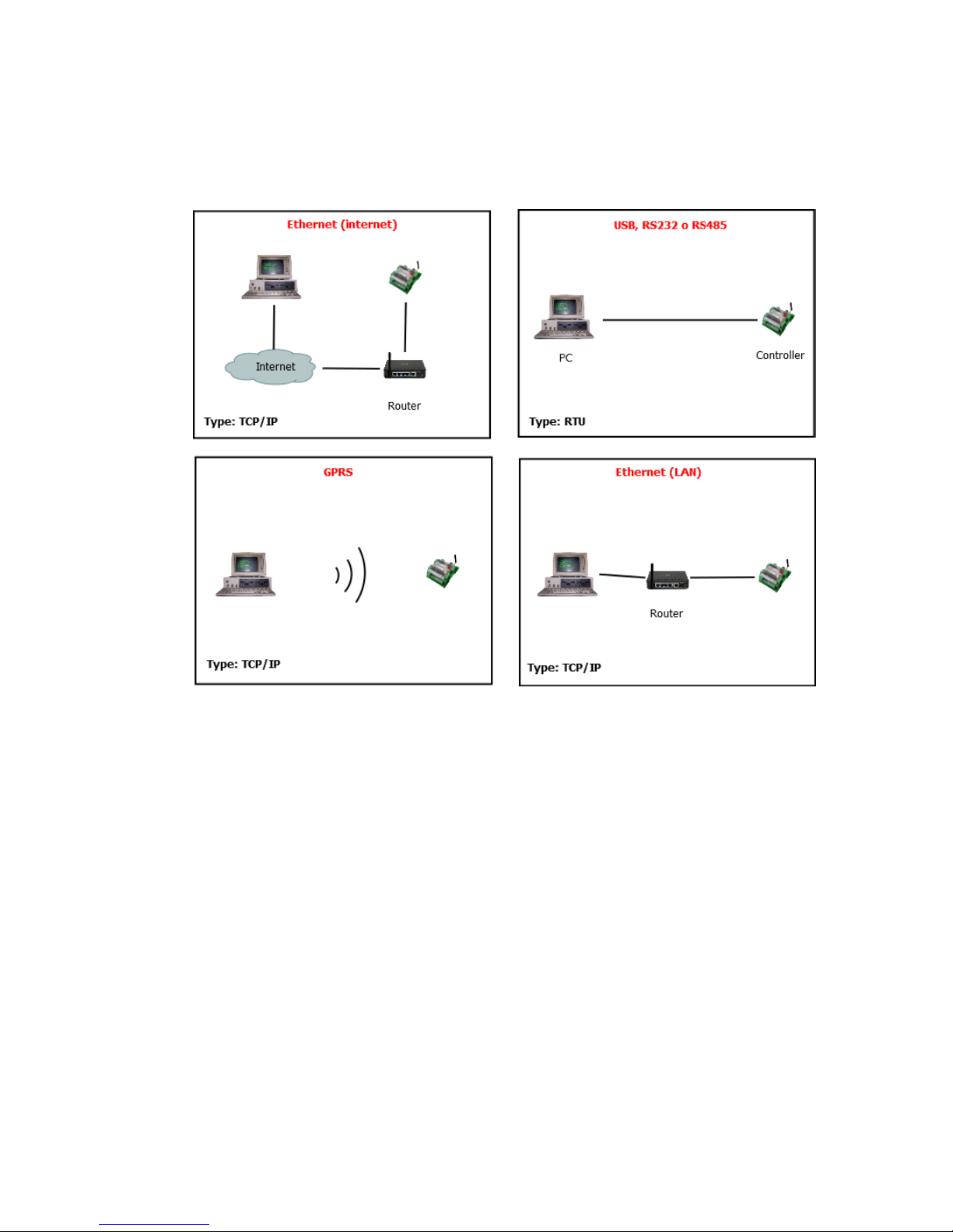
In the following Figure, the most typical connection schemes of MX-9 with PC are shown. The
Configuration Tool described in this document or any other Modbus complaint software can
establish a communication link making use of Modbus RTU and/or Modbus TCP protocols.
Figure 7. MX-9 typical connection diagrams
3 "Start" tab
3.1 MX-9 Basic Information
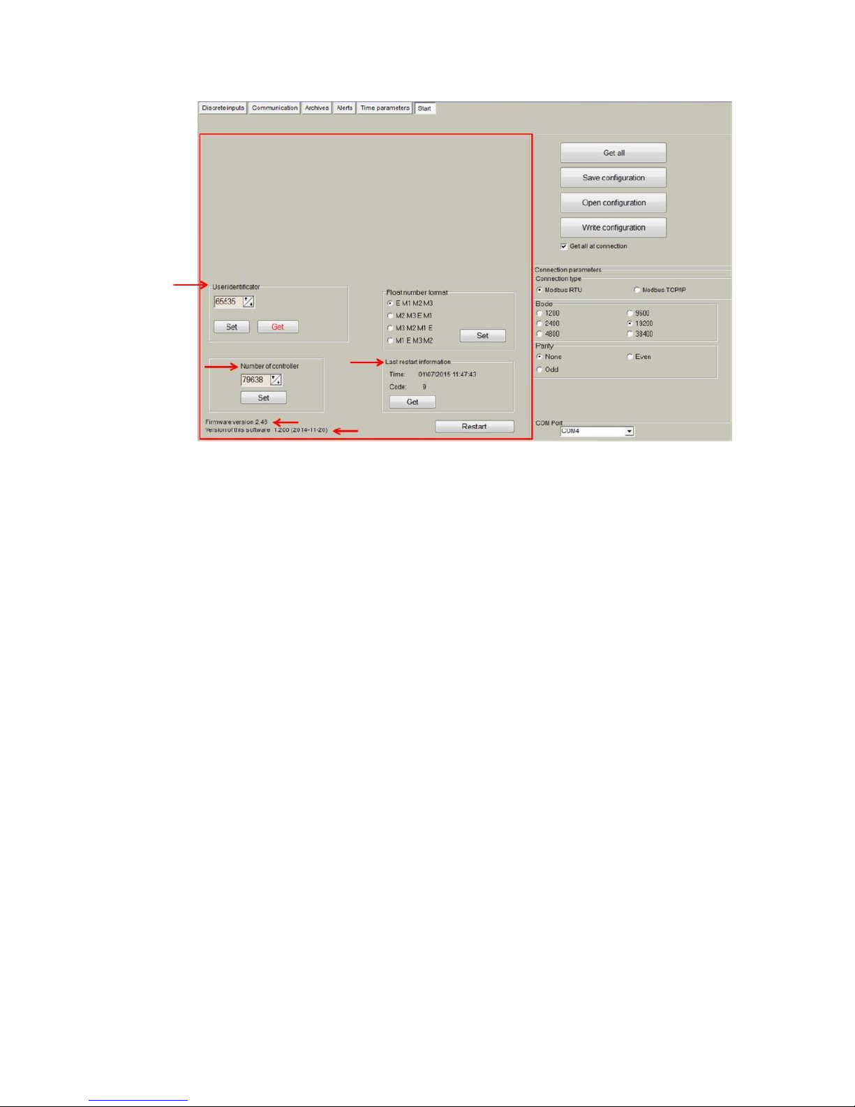
Once user has established communication with MX-9, basic information such as "User
identificator" , "Serial number", "Last restart", "Firmware version","Software version", etc. is
shown in the left frame
Page 8
8
Figure 8. “Start” tab. MX-9 basic information
3.2 Configuration files
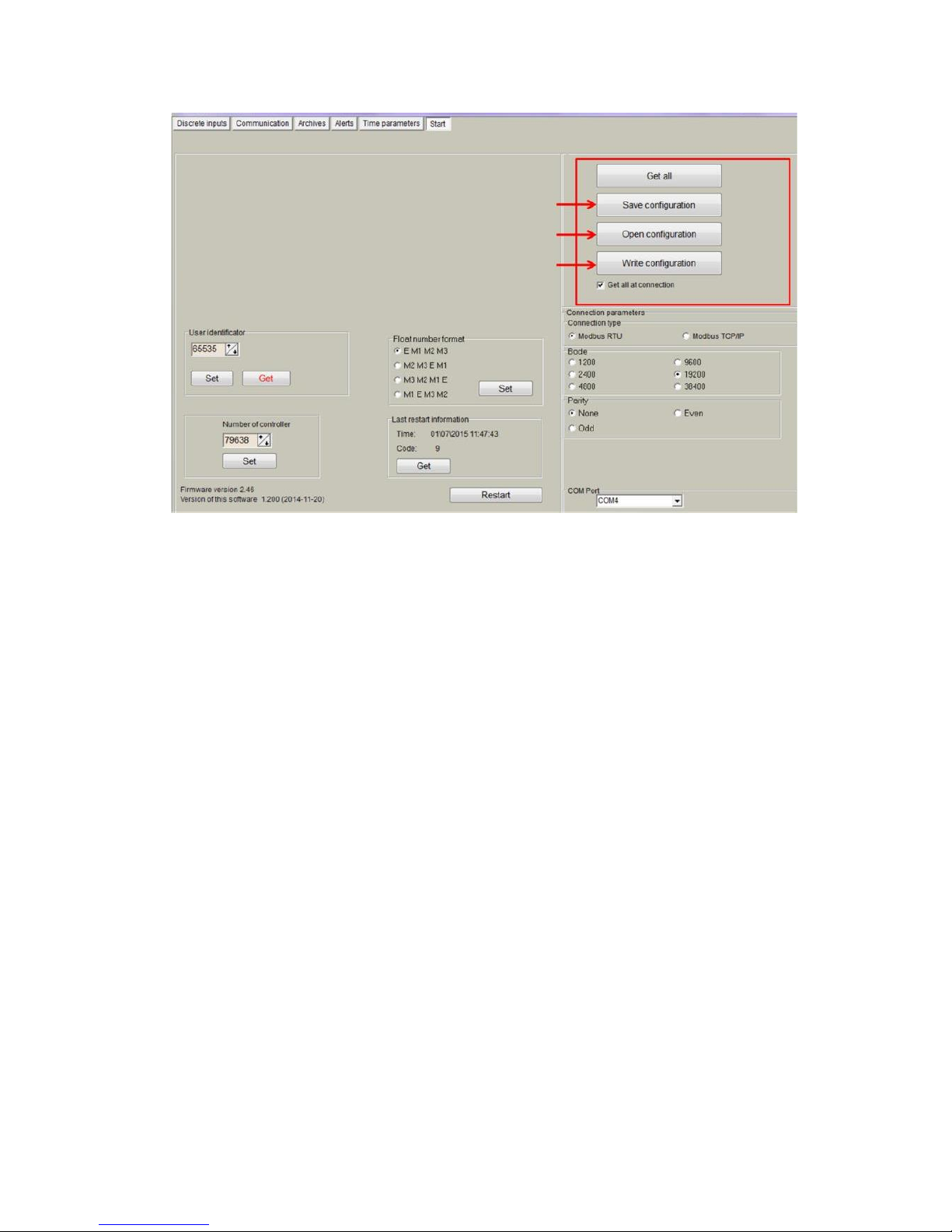
This feature enables user to save and load configuration files so that programming a number of
controllers with the same configuration becomes an easy process. Steps to be followed are:
1. Set up all the configuration parameters making use of MX-9 Configuration Tool.
2. Then, under “Start” tab, click on "Save configuration" button. A dialog will be shown
requesting user to select folder destination.
3. Once the file has been stored, connect a new controller to the PC and then click on "Open
configuration" and select the file previously stored.
4. Then, click on "Write configuration" button to load such configuration into the new
controller.
5. A restart will be needed so that controller can start using the loaded configuration.
6. Repeat from step 3 with all the controllers that need the same configuration.
Page 9
9
Figure 9. “Start” tab. Configuration files management
3.3 Status indicators
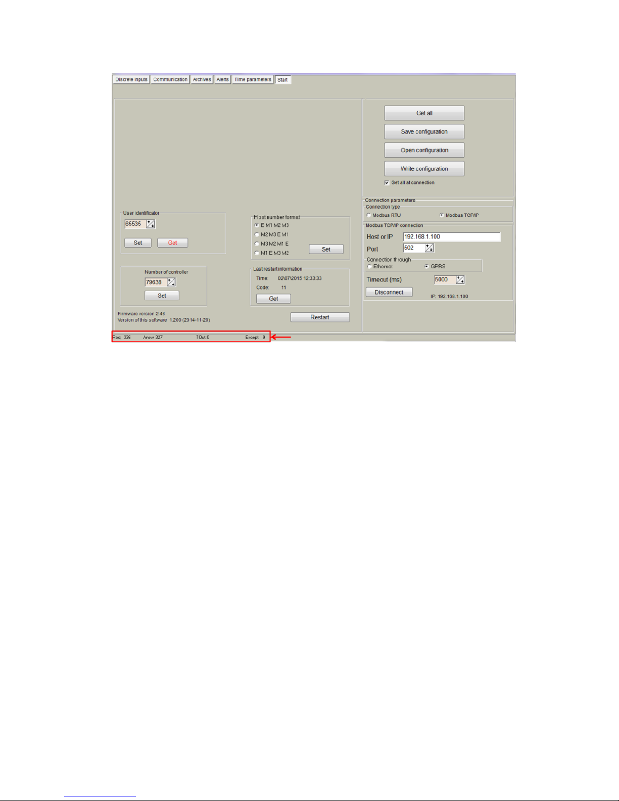
Several status indicators are shown in the MX-9 configuration tool in order to inform user about
current performance of Modbus communication:
1. Req: number of Modbus requests performed.
2. Answ: Number of Modbus answers received.
3. Tout: number of Modbus requests not answered (time outs raised).
4. Except: number of Modbus errors.
Page 10
10
Figure 10. “Start” tab. Status indicators
4 “Discrete inputs” tab
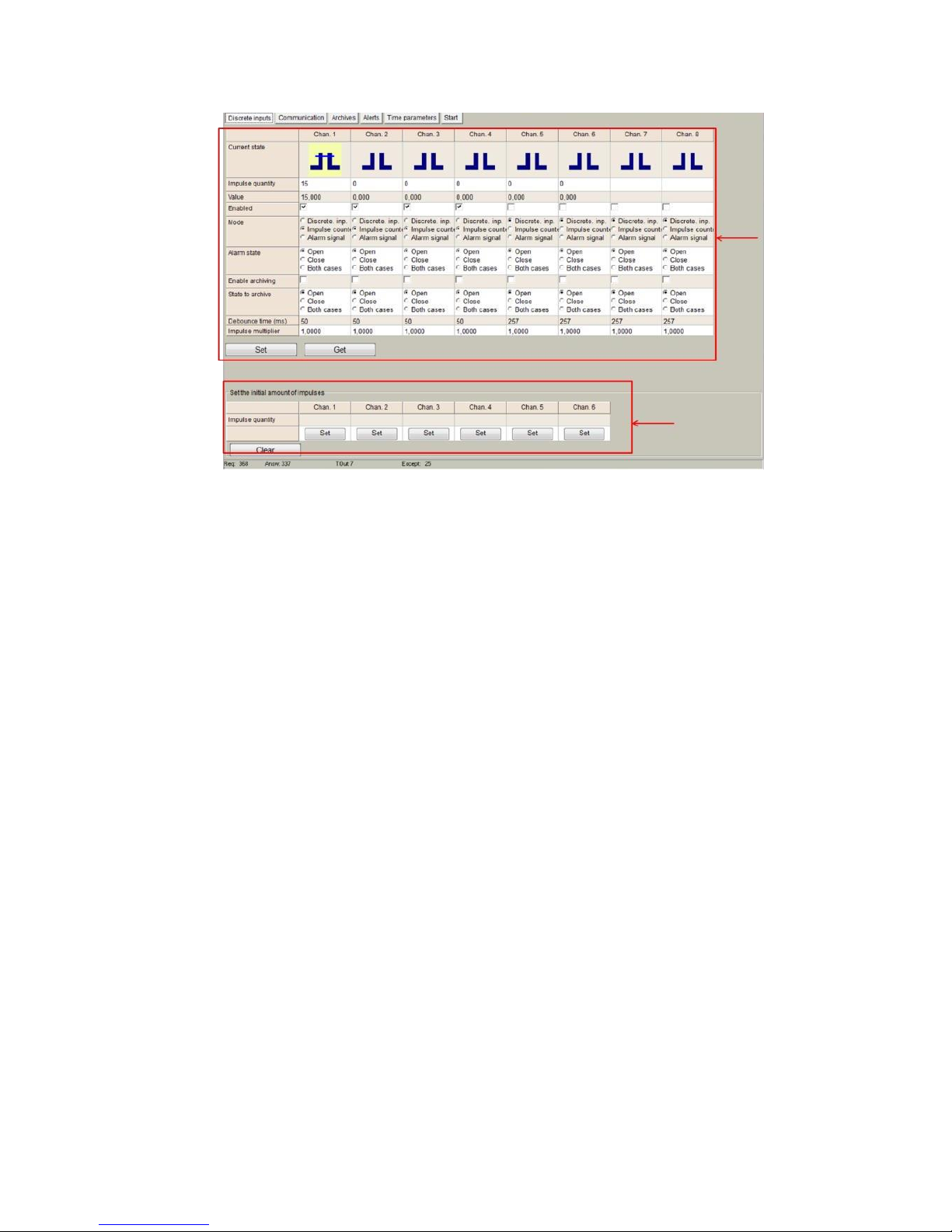
Discrete inputs can be configured within this tab. They are shown organized in columns and
configuration parameters are shown in rows as follows:
"Current State": Graphical representation of current status (open/closed).
"Impulse quantity": Number of pulses counted from last reset.
"Value": Calculated from multiplying number of pulses counted (Impulse quantity) and
user-defined multiplier (Impulse multiplier).
"Enabled": user enable/disable discrete inputs to be used. In order to save memory, it is
recommend to only enable inputs in use.
"Mode":
"Discrete Input": input works as a standard discrete input detecting its current state (1 /
0)
"Impulse counter": input is used as a standard pulse counter, storing the amount of pulses
raised.
“Alarm signal”: input is used as an alarm input.
"Alarm state": If "Alarm signal" option is selected, controller will raised an alarm when one
of the following state is reached: "Open", "Close", "Both cases".
"Enable archiving": If enabled, events produced by discrete inputs are stored in the
datalogging archive.
"Debounce time": only pulses received within one or more “Debounce time” intervals are
registered.
"Impulse multiplier": user-defined multiplier. Values can be set from 1 to 1000. "Set initial
amount of pulses": initial value for pulse counter can be set here.
NOTE: After configuration is completed, click on "Set" button in order to save changes.
Page 11
11
Figure 11. “Discrete inputs” tab
5 “Communication” tab
5.1 Communication > Ethernet
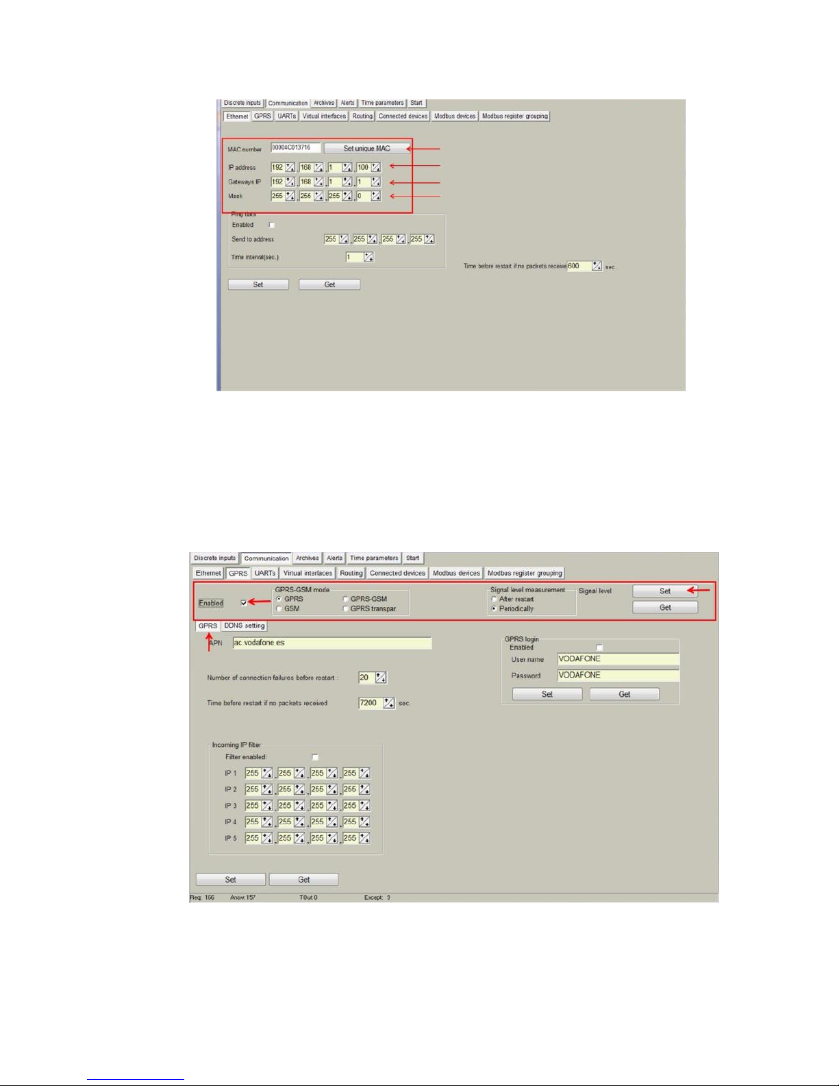
Ethernet interface parameters can be configured within this tab:
"MAC number": Media Access Control address
"IP address"
"Gateway IP"
"Mask"
NOTE: After configuration is completed, click on "Set" button in order to save changes.
Page 12
12
Figure 12. “Ethernet” Configuration tab
5.2 Communication > GPRS
As previously described, MX-9 can be configured through a GPRS link. In order to do so,
user must enable GPRS connection as shown below. Then, click on "Set" button in order
to save changes.
Figure 13. “GPRS” Tab. Enabling communication
Page 13
13
Within this tab, different services can be configured or checked.
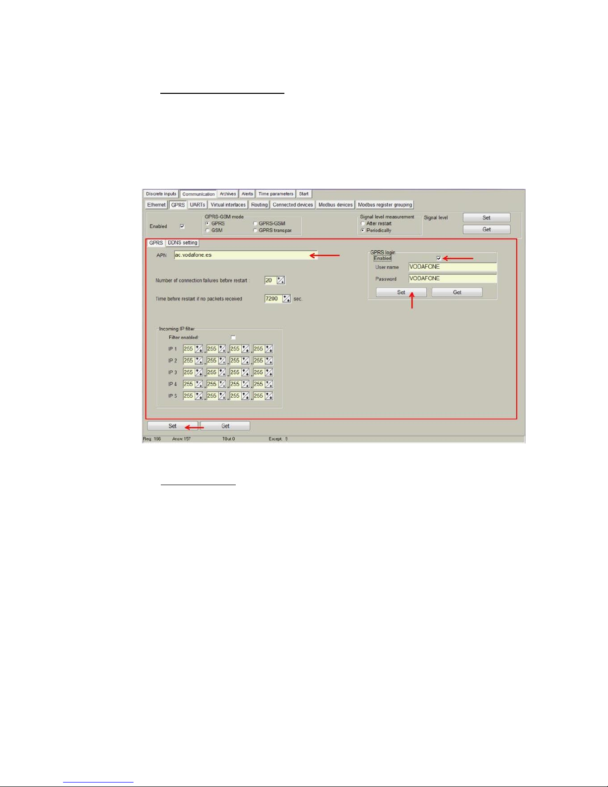
1. GPRS connection parameters:
"APN": access point name provided by Internet Service Provider (ISP).
If needed by ISP, credentials can also be configured here:
"Username": provided by ISP.
"Password": provided by ISP.
NOTE: After configuration is completed, click on "Set" button in order to save changes.
Figure 14. “GPRS” tab. Internet Service Provider access data configuration
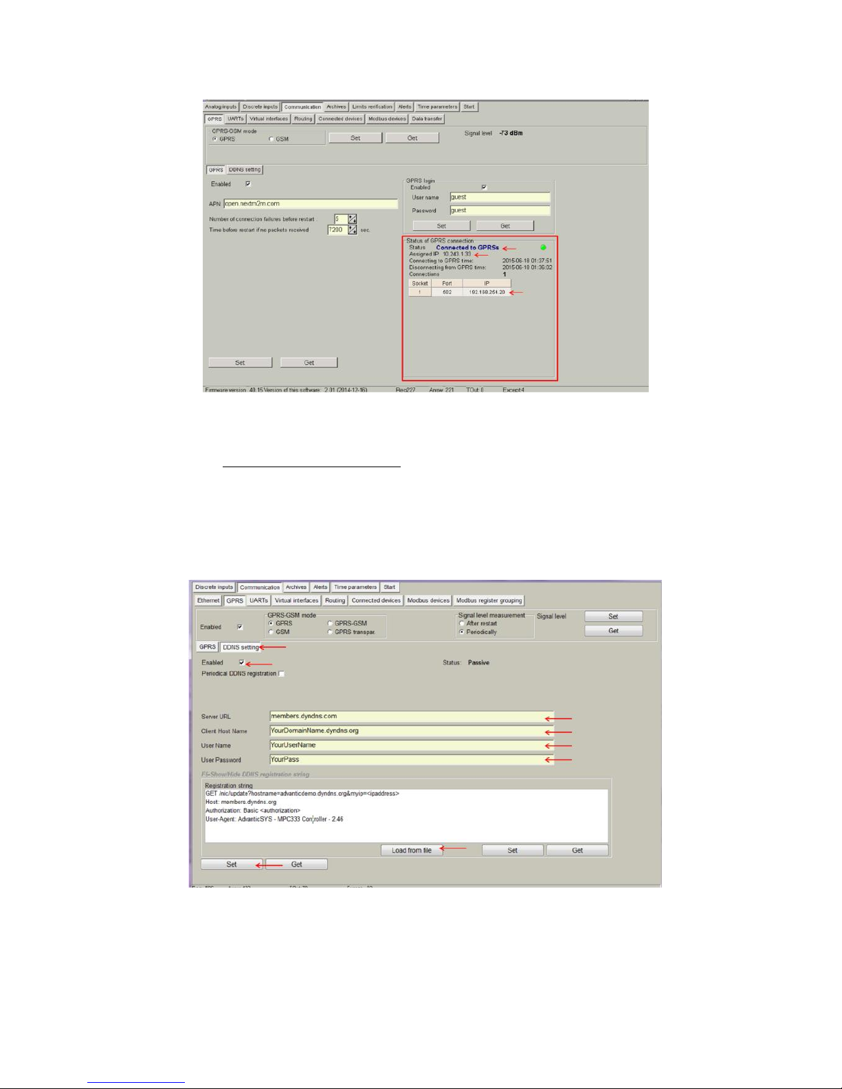
2. Connection status. Once GPRS connection is established, status will be shown as
below:
Page 14
14
Figure 15. “GPRS” tab. Connection status
3. DynDNS account configuration: in order to avoid the need to have a fixed IP
address to be able to remotely access the device, it is possible to set up a
DynDNS account under the "DDNS setting". Steps to be followed are:
Select “Enable”
Fill in information according to your DynDNS account
Click on "Load from file" and select "dyndns.org_Register_String.txt "
which contains the connection string to be sent to DynDNS servers.
Figure 16. “GPRS” tab. DynDNS configuration
NOTE: After configuration is completed, click on "Set" button in order to save changes. NOTE:
It is recommended to disable GPRS connection if not used.
Page 15
15
5.3 Communication > UARTs
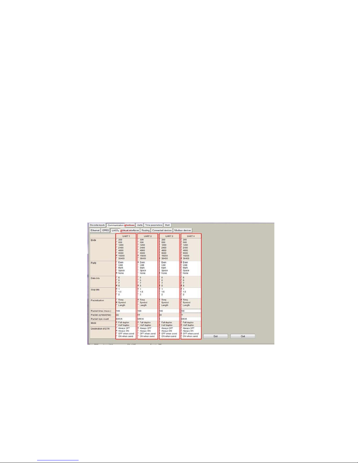
Each UART can be configured individually. It is recommended to check peripheral devices
UART constraints before setting up parameters in the controller configuration tool.
NOTE: All devices connected to the same MX-9 UART must have the same communication
parameters.
"Bode": Transmission rate (bauds per second).
"Parity": Communication Parity.
"Data bits": Number of data bits within the communication packet.
"Stop bits": Number of stop bits within the communication packet.
"Packetization":
"time": One packet time has been reached, it is considered that the
packet has been properly sent.
"Symbol". Every time a "packet symbol" is received, it is considered that
the packet has been properly sent.
“Length”. Once the "packet byte count" has been reached, it is
considered that the packet has been properly sent.
“Packet time”: Transmission duration.
“Packet symbol”: Symbol which defines packet ending.
“Packet byte count”: Length which defines packet size
“Mode”: Full duplex or half duplex
“Destination of DTR”: bit which defines the "Data ready" state has been
reached. It must be configured following peripheral devices connected to
MX-9 UARTs vendor information. By default, if this information is not
available, it is recommended to select "OFF when send" option.
NOTE: After configuration is completed, click on "Set" button in order to save changes.
Figure 17. “UARTs” tab
5.4 Communication > Virtual interfaces
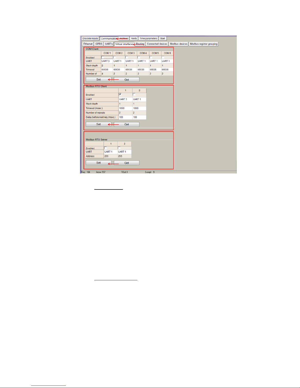
The MX-9 can perform as communication gateway Modbus server/client and datalogger
simultaneously. In order to set up these options, different virtual interfaces are needed as
shown below
Page 16
16
Figure 18. “Virtual interfaces” tab
"COM Client". It is needed to configure a COM Client every time a
“transparent” communication mode or M-Bus compatibility is needed. This is
mandatory in order to read devices not compatible with Modbus RTU/TCP
protocols. Configuration parameters are:
"Enable": Do not enable any COM client if not needed.
"UART": Select the UART number in which a COM Client will be configured.
NOTE: Once a given UART is selected to be a COM client, it cannot be used with
any other configuration such as Modbus client/server.
"Stack depth": number of parallel executions that can be done in parallel by
the COM client.
“Timeout”: it defines the amount of milliseconds defined as time out.
"Number of repeats": number of retries defined in case of transmission error.
NOTE: COM Client must always be used when peripheral devices connected
to a given UART use protocols such as M-Bus, IEC-102, DLMS, etc.
NOTE: After configuration is completed, click on "Set" button in order to save
changes.
"Modbus RTU Client". This mode working mode must be used when the MX-
9 behaves as master in a Modbus RTU network (it sends Modbus requests
to the slaves connected to the Modbus RTU network). These requests will
be defined under the "Modbus devices" tab. Parameters to be configured
are:
"Enable": Do not enable any Modbus RTU client if not needed.
"UART": Select the UART to be associated to the Modbus RTU client.
NOTE: Once a given UART is selected to be a Modbus RTU client, it cannot be
used with any other configuration such as COM client.
"Stack depth": number of requests that can be stacked in the UART buffer.
It is recommended to set this value to 1 by default.
“Timeout”: it defines the amount of milliseconds defined as time out.
"Number of repeats": number of retries defined in case of transmission error.
Page 17
17
"Delay before next request": In case peripheral devices need some “extra
time” to answer after a received request
NOTE: After configuration is completed, click on "Set" button in order to save
changes.
"Modbus RTU Server". This mode is used when the MX-9 will be used as
Modbus slave in a network. Requests from a Modbus server will be received
and answered.
"Enable": Do not enable any Modbus RTU server if not needed.
"UART": Select the UART to be associated to the Modbus RTU server.
NOTE: Once a given UART is selected to be a Modbus RTU server, it cannot be
used with any other configuration such as COM client.
"Address": Define Modbus address for MX-9. Modbus master must send
requests to the given address.
NOTE: After configuration is completed, click on "Set" button in order to save
changes.
5.5 Communication > Data transfer
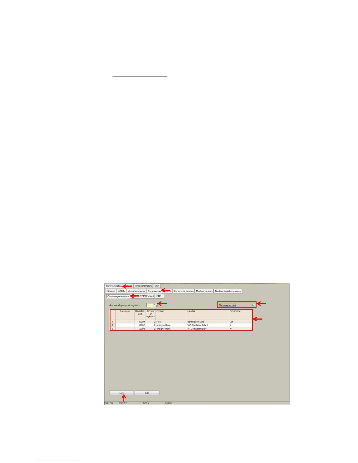
Data collected by MX-9 can be sent in two different ways: FTP and MQTT protocols. In
both cases, parameters to be sent must be configured by setting up the data structure
following the next steps:
Go to Communication>Data transfer>Common parameters> and configure the
following parameters:
"Amount of group of registers": Number of registers or group of registers to be stored
in the CSV file.
"Set user archive". If selected, it enables automatic storage of selected registers in
the internal memory. It is recommended to always select this option so that in case
of file transmission failure, data can be retrieved and resent when communication is
reestablished.
"Parameter". It is filled in automatically.
"Register/Coil" Initial Modbus register address.
“Amount of registers”. Number of registers to be stored from the initial Modbus
registers address.
"Format": Data type of registered parameter.
"Header": Fixed column header to be written in CSV file.
"Dimension": Extra column in which data units can be stored.
Figure 19. “Data transfer” tab. CSV file structure definition
Page 18
18
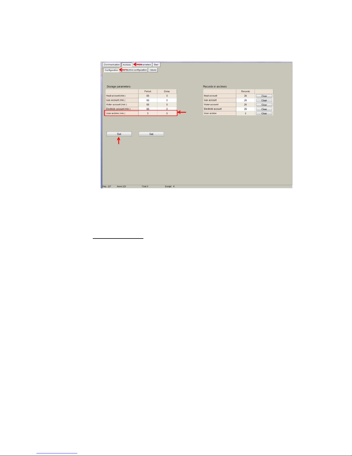
NOTE: Go to Archives>Configuration and specify ´User archive (min)´
value to set the datalogging period as shown in the following figure.
Figure 20. Setting up Datalogging period
NOTE: After configuration is completed, click on "Set" button in order to
save changes.
After configuring data structure, user can select in which way the device will send data. It
can be sent in a csv file to a remote FTP server or in a JSON formatted message to an
MQTT Broker.
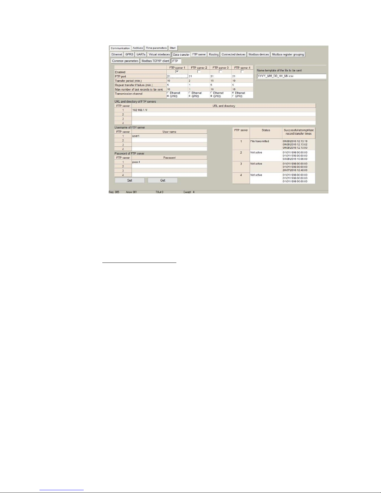
1. Configure FTP client: Go to Communication>Data transfer>FTP> and configure the
following parameters:
“FTP server”: Up to 4 different FTP connections to remote FTP servers
can be configured.
"Enabled": Select it to enable an FTP connection
"FTP Port": By default, 21 but can be changed.
"Transfer period": It defines interval between CSV file sending
tasks.
"Number of last records to be read": It defines maximum number of
previous data stored and not sent due to communication error.
These data will be sent in a CSV file when communication is
restored.
"Transmission channel": It can be Ethernet or GPRS
“URL and directory of FTP servers”: It defines the complete FTP
server URL where CSV file will be hosted.
Username and password of FTP server: to be configured in case
credentials are requested by FTP server.
Page 19
19
Figure 21. “Data transfer” tab. FTP client configuration
NOTE: In order to synchronize user archive storage and csv sending file through FTP link, the
following constraints must be taken into account:
"User archive sample time" must be equal or below the FTP "transfer period"
FTP "Repeat transfer if failure” time is recommended to be about half time of FTP "transfer
period".
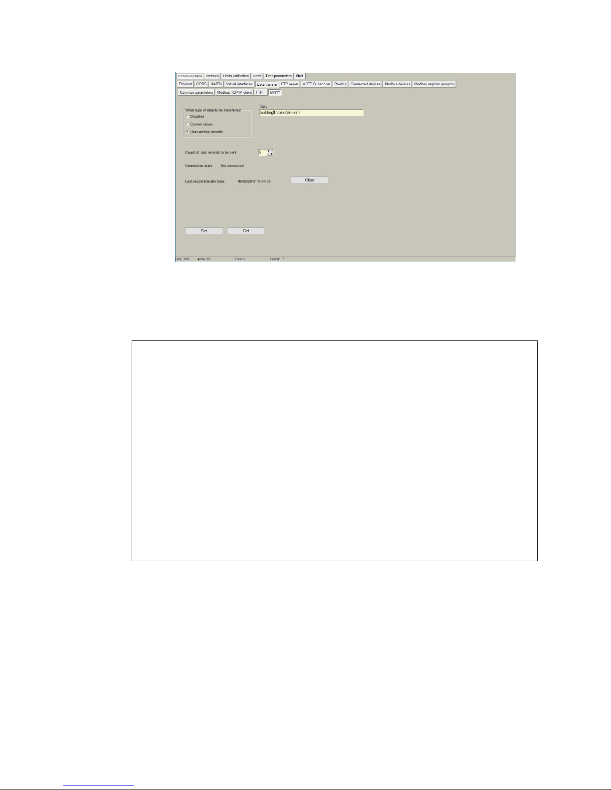
2. Configure MQTT publisher: Go to Communication>Data transfer>MQTT> and
configure the following parameters:
“Topic”: A topic is a UTF-8 string, which is used by the broker to filter messages for each
connected client. A topic consists of one or more topic levels. Each topic level is
separated by a forward slash (topic level separator). Example: “building1/zoneA/room2”
“What type of data to be transferred”: It defines the functionality the device will have with
regard to MQTT data sending:
“Disabled”: if selected, the device will not send anything through MQTT port.
“Current values”: MX-9 will send real time values of parameters configured in Common
Parameters tab. In this case, sampling/sending period can be set from 1 to 86400
seconds.
“User Archive records”: this feature sends data every datalogging period set in
Archives>Configuration>´User archive (min)´ value.
NOTE: After configuration is completed, click on "Set" button in order to save
changes and “RESTART” (start menu>restart).
Page 20
20
Figure 22. “Data transfer” tab. MQTT configuration
Once properly configured both this tab and Communication>MQTT Subscriber one, JSON
formatted messages will be sent to the MQTT Broker (for example, RabbitMQ) In the
following example, a “user archive records” message with a discrete input status is sent:
{
"SN":"86004",
"name":"MX-9",
"header":{
"startTime":"2016-02-07T15:06:00.000Z",
"endTime":"2016-02-07T15:06:00.000Z",
"recordCount":2,
"columns":{
"0":{
"id":"0",
"name":"relay1",
"dataType": "NUMBER",
"format":"unsigned short"
}
},
"data":[
{
"ts":"2016-02-07T15:06:00.000Z",
"f":{
"0":{"v":0}
}
}
]
}
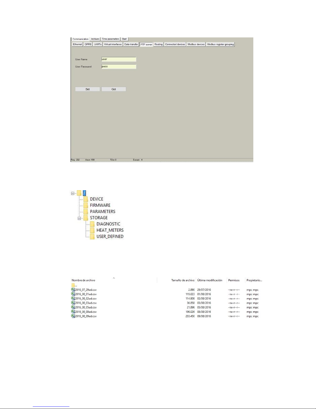
5.6 Communication > FTP Server
If the MX-9 has a micro SD card installed, it can act as FTP server. In this tab, user can
configure both user and password to be used as credentials to enter into the internal file
system through an FTP connection.
Page 21
21
Figure 23. “Communication > FTP server” tab.
Once properly configured, user can access the internal file system making use of any FTP
client (such as Filezilla).
The file system structure is as follows:
In the root, a “CURRENT_DATA.csv” file is stored. You will find all the data generated by
the MX-9 configured in “Communication > Data Transfer > Common parameters” tab and
not yet sent to the remote FTP server.
Moreover, under “Storage” folder, files for each of the archives set in the “Archives” tab can
be found. They are created on a daily basis.
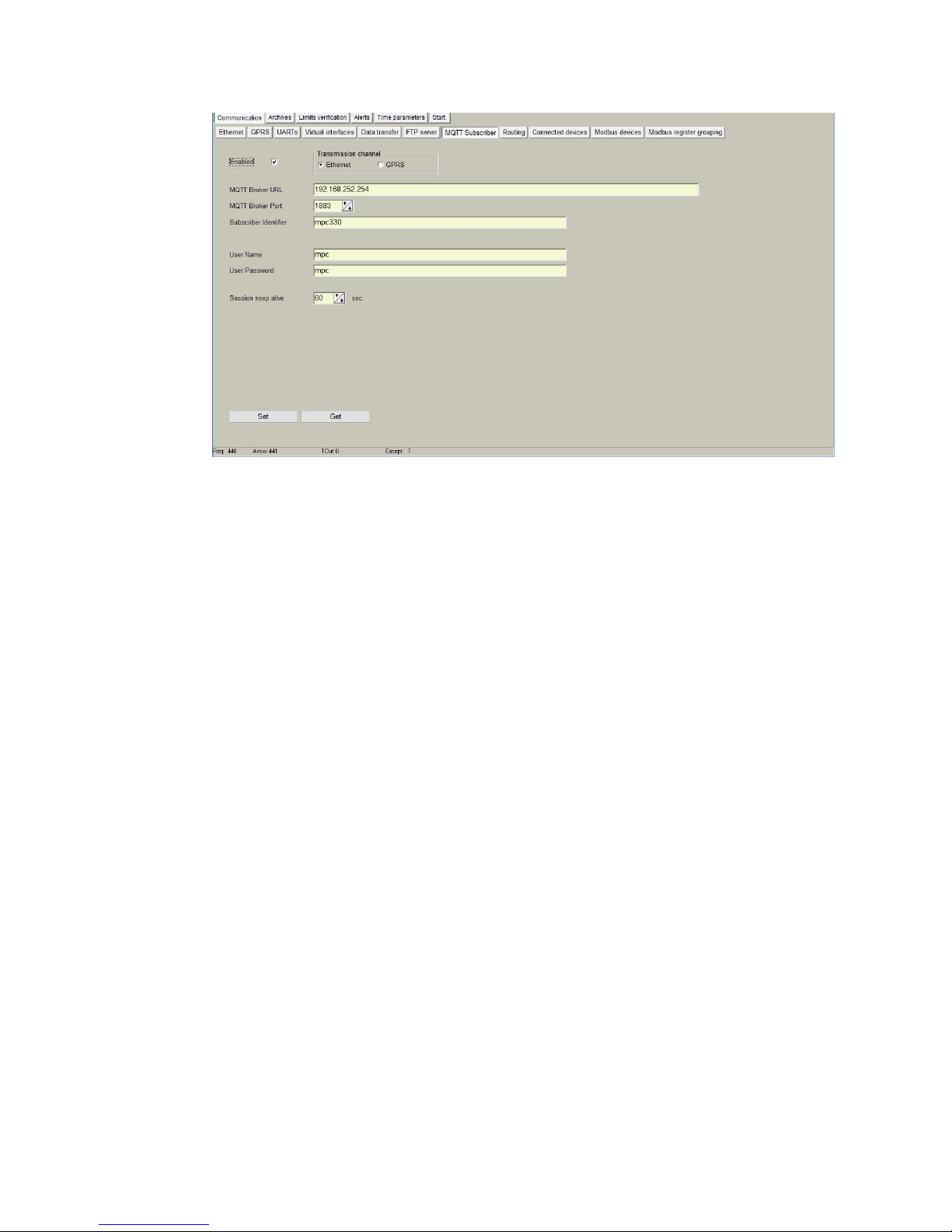
5.7 Communication > MQTT Subscriber
If the MX-9 supports MQTT protocol, within this tab, user will need to configure MQTT
Broker (remote server towards data will be sent). it can act as FTP server. In this tab, user
can configure both user and password to be used as credentials to enter into the internal
file system through an FTP connection.
Page 22
22
Figure 24. “Communication > MQTT Subscriber” tab.
This protocol needs to have a central server that will collect all the data sent by the MX-9.
Thus, first of all, user must enable this mode. In addition, the following parameters must be
configured: o "MQTT Broker URL": This is the server URL where data will be sent to
"MQTT Broker Port": By default, MQTT protocol is 1883 but it can be change in this
box.
"Subscriber identifier": This is the device identifier.
“User name”: Broker user with credentials to publish messages.
"User password": Broker password.
"Session keep alive": number of seconds the session is kept alive after message has
been sent. By default, 60 secons.
NOTE: After configuration is completed, click on "Set" button in order to
save changes.
5.8 Communication > Routing
Since MX-9 can work as a communication gateway, several routing modes can be
implemented in it. When used as gateway, all the information received by MX-9 is
forwarded following the chosen configuration, not storing any of these data in its memory:
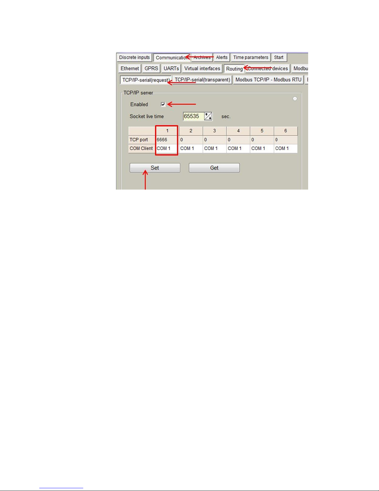
TCP/IP - serial (request)
Making use of this mode, two devices can be connected between a TCP/IP
port and a UART. In this case, the TCP/IP device must initiate communication
and the RS485/RS232 will answer under “request”.
Parameters to be configured are:
"Enabled": Mode enabling/disabling.
"Socket live time": Duration in which socket is kept active. When
the device initiating communication sends a request command to
the slave device, communication will be shut down when this
time is reached.
Routing 1,2,3,4,5,6:
“TCP port”: Routing is done through this port.
“COM client”: Previously configured under “Communication >
Virtual interfaces” tab
NOTE: After configuration is completed, click on "Set" button in order to save
changes.
Page 23
23
Figure 25. “Communication > Routing” tab. TCP/IP - serial (request)
routing configuration
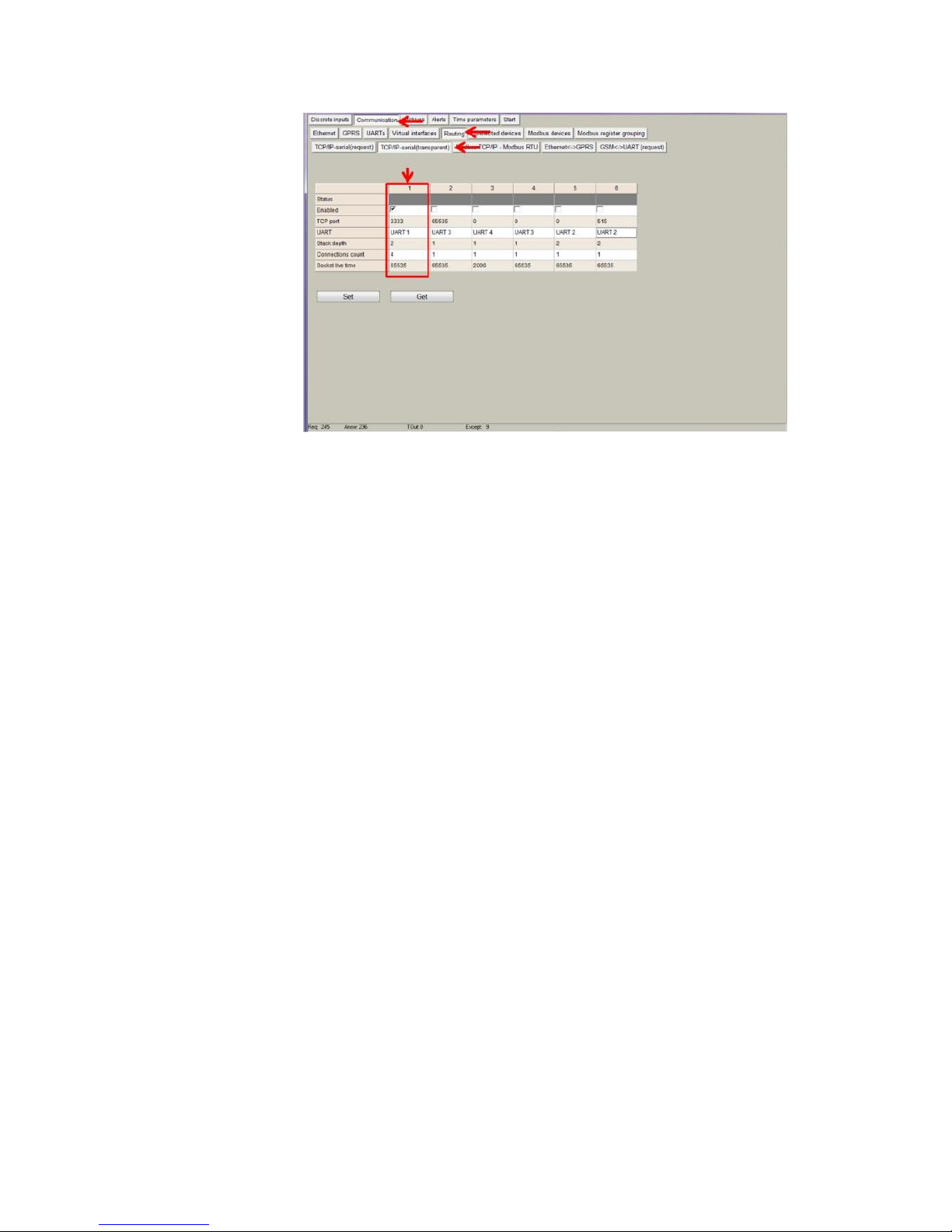
TCP/IP - serial (transparent)
Making use of this mode, two or more devices can be connected between a
TCP/IP port and a UART. In this case, any device can initiate communication.
The MX-9 manages several communications seamlessly. Parameters to be
configured are:
Routing 1,2,3,4,5,6:
"Enabled": Mode enabling/disabling.
“TCP port”: Routing is done through this port.
“UART”: Previously configured under “Communication > UARTs”
tab.
"Stack depth": Number of concurrent transmissions.
"Connections count": Number of devices to be connected.
"Socket live time": Duration in which socket is kept active. When
the device initiating communication sends a request command to
the slave device, communication will be shut down when this
time is reached.
NOTE: After configuration is completed, click on "Set" button in order to save
changes.
Page 24
24
Figure 27 “Communication > Routing” tab. TCP/IP - serial
(transparent) routing configuration
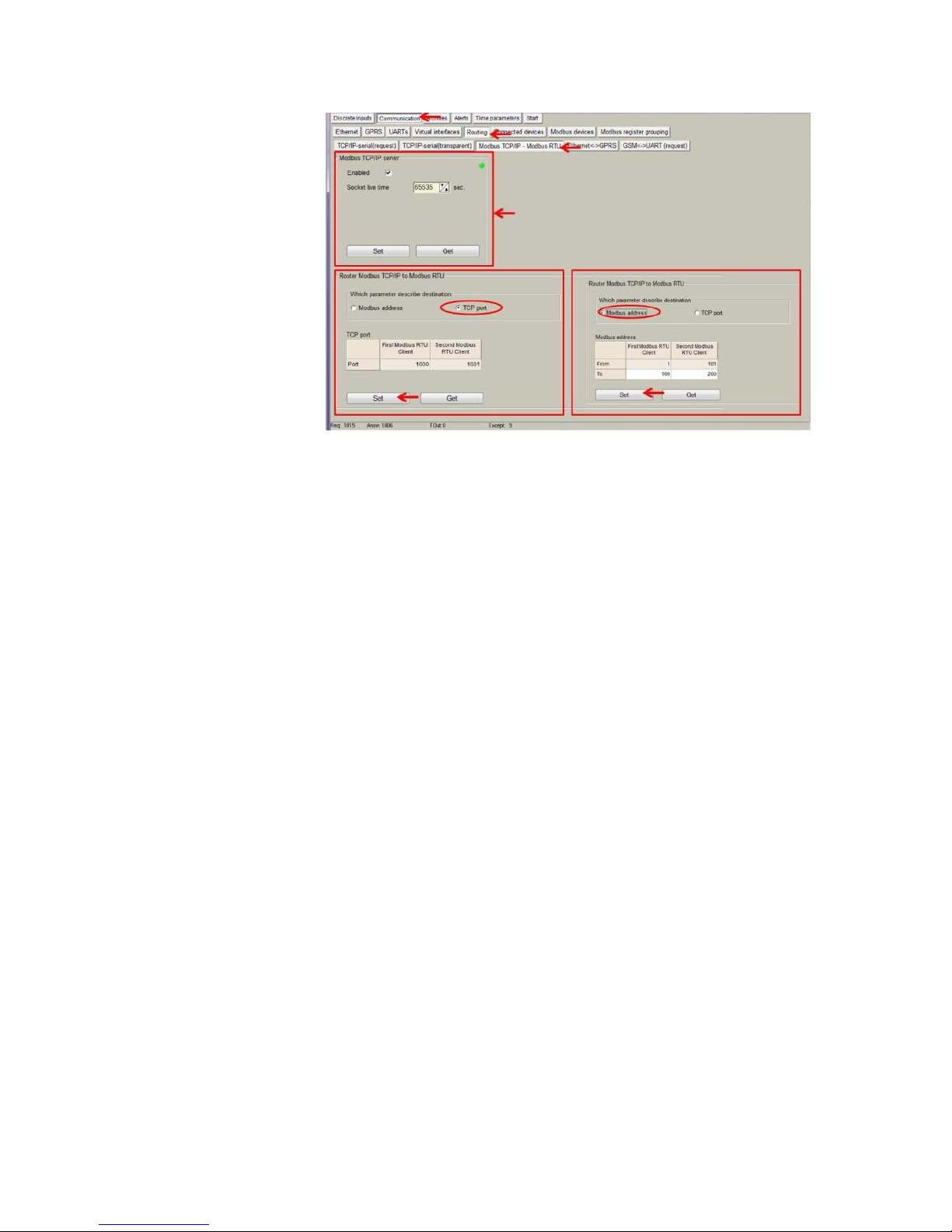
Modbus TCP/IP - ModBus RTU
The MX-9 can also forward Modbus packets from a TCP port to an Modbus
RTU client. In order to do so, Modbus TCP/IP server mode must be always
enabled as shown in the figure. Also "Socket live time" parameter must be
configured given that it is the duration in which socket is kept active. When
the device initiating communication sends a request command to the slave
device, communication will be shut down when this time is reached.
This routing mode can be done in two ways:
Destination "TCP port": This mode enables assignment of a TCP port to
each Modbus RTU device as previously configured under
Communication>Virtual interfaces>Modbus RTU Client tab.
Destination "Modbus address": Within this mode, user can identify Modbus
addresses to each Modbus RTU device as previously configured under
Communication>Virtual interfaces>Modbus RTU Client tab. With this
configuration, Modbus commands can be sent to devices within the
network making use of the specific device Modbus address and the MX-9
IP address and TCP port 502.
NOTE: After configuration is completed, click on "Set" button in order to save
changes.
Page 25
25
Figure 28. “Communication > Routing” tab. Modbus TCP/IP –
Modbus RTU routing configuration
5.9 Communication > Connected devices
Within this section, both M-Bus and Wireless M-Bus communication can be configured
given that MX-9 is able to collect data from up to 8 M-Bus and up to 50 Wireless MBus
devices.
In the following pages, a detailed description of each M-Bus and Wireless M-Bus meter
configuration step is done.
5.9.1 M-Bus devices
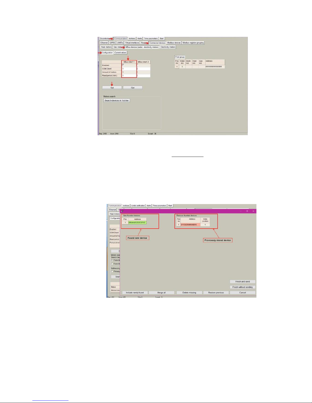
Steps to be followed are:
Enable COM Client under Communication>Virtual interfaces>COM
Client tab.
Go to Communication > Connected devices > Mbus devices >
Configuration and configure the following parameters:
"Enabled": Select which MBus interface will be active.
"COM Client": Select COM Client previously configured.
"Amount of meters": Configure the number of M-Bus devices
to be read.
"Read Period": Reading interval in minutes.
Page 26
26
Figure 29. “M-Bus devices” tab. Communication configuration
NOTE: After configuration is completed, click on "Set" button in order to
save changes. Also, perform a hardware reset.
• Once MX-9 has been restarted, go to
Communication>Connected devices>Mbus
devices>Configuration and click on "Search devices in 1st line"
button.
After a few seconds, a list including all the M-Bus devices connected to
the network will appear:
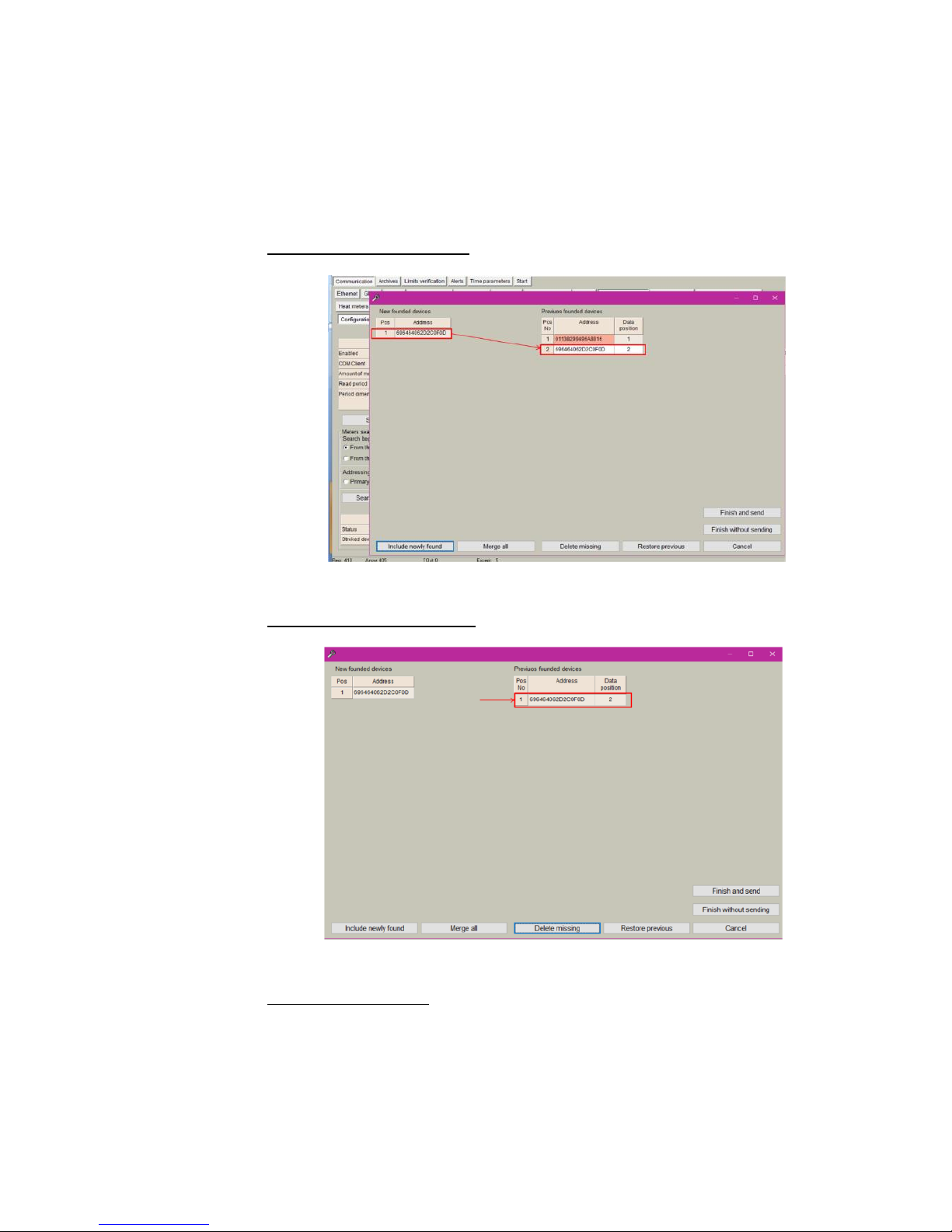
Figure 30. MBus devices Self-discovery and steps to be followed.
Once a new device is discovered, it must be added to the Mbus client, the
following steps must be followed:
• Click on ”Include newly found”
• Click on “delete missing” if you want to delete old meters which
are not needed.
• Click on “Finish and send”
If several new devices are discovered, the following steps should be done:
Page 27
27
• Click on “Merge all”
• Click on “Finish and send”
All devices online appear in green and the ones offline in red.
An step-by-step guide is shown in the following figures:
STEP 1: Including new devices
Figure 31. New device included in the M-bus client.
STEP 2: Delete missing devices
Figure 32. After delete missing
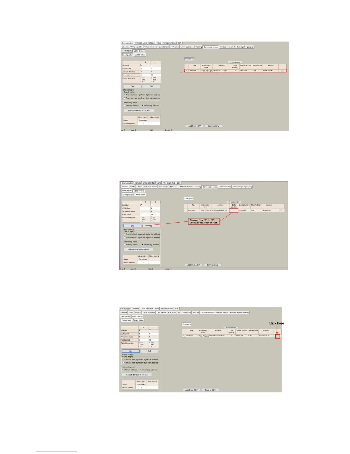
STEP 3: Finish and send
Page 28
28
Figure 33. After finish and send
Once the new device is added to the Mbus client, it is recommended to
modify the data position count in order to optimize the internal memory
of the controller (from 2 to 1 in the example above). Once updated, click
on "SET":
Figure 34. Updating data position
Once the M-bus client is configured, it is possible to read data available in the
meter:
Figure 35. Click on "data/parameters" button
Page 29
29
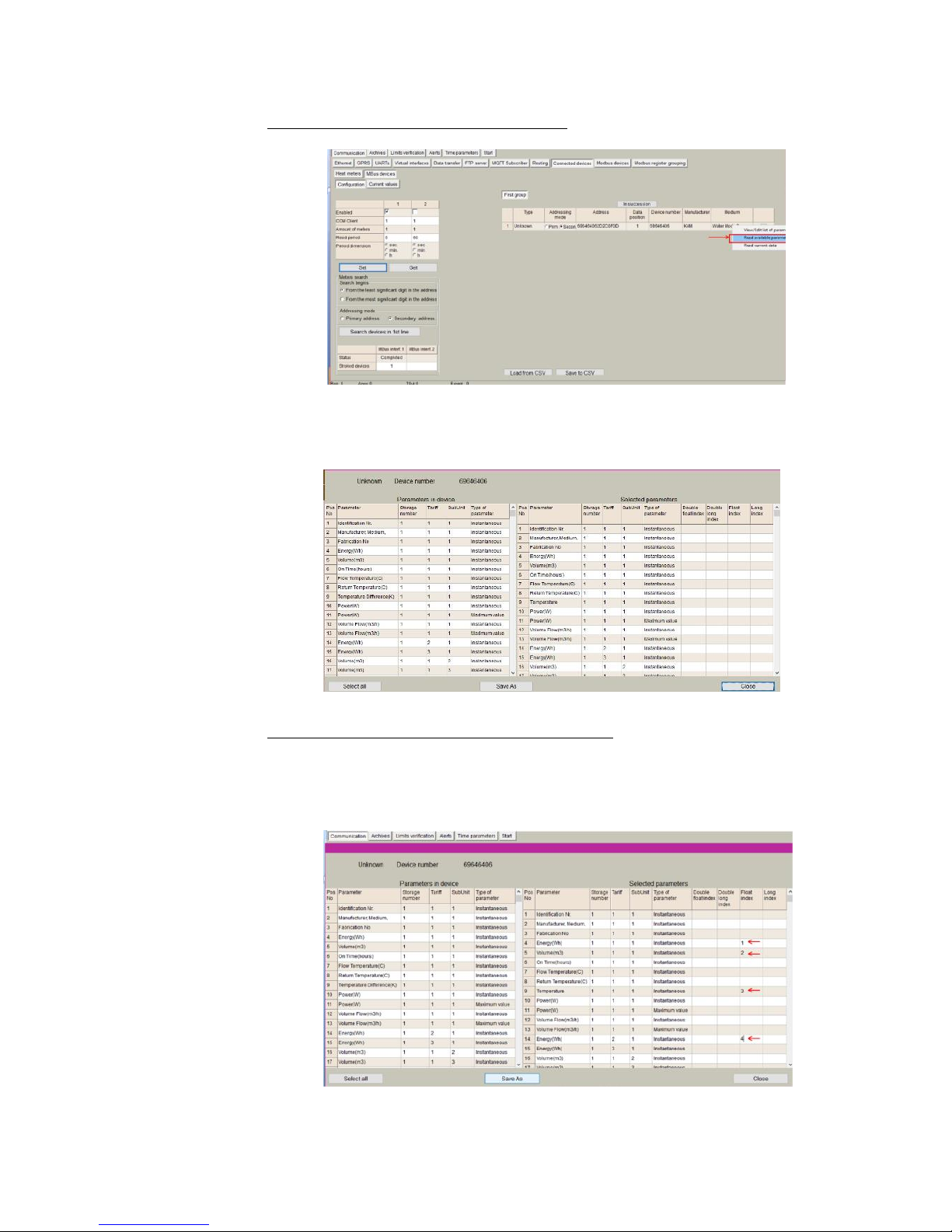
STEP 4: Click on "Read available parameters"
Figure 36. Read available parameters
A list of parameters will be shown. User must select which parameters provided
by the M-Bus devices should be stored in the internal MX-9 memory.
Figure 37. List of available parameters
STEP 5: Select M-Bus meter parameters to be stored
Each selected parameter must be configured with an ordering index according
to the data format that the meter presents in its datasheet. This index will order
the stored data in the internal memory map.
Figure 38. List of parameters indexes.
Page 30
30
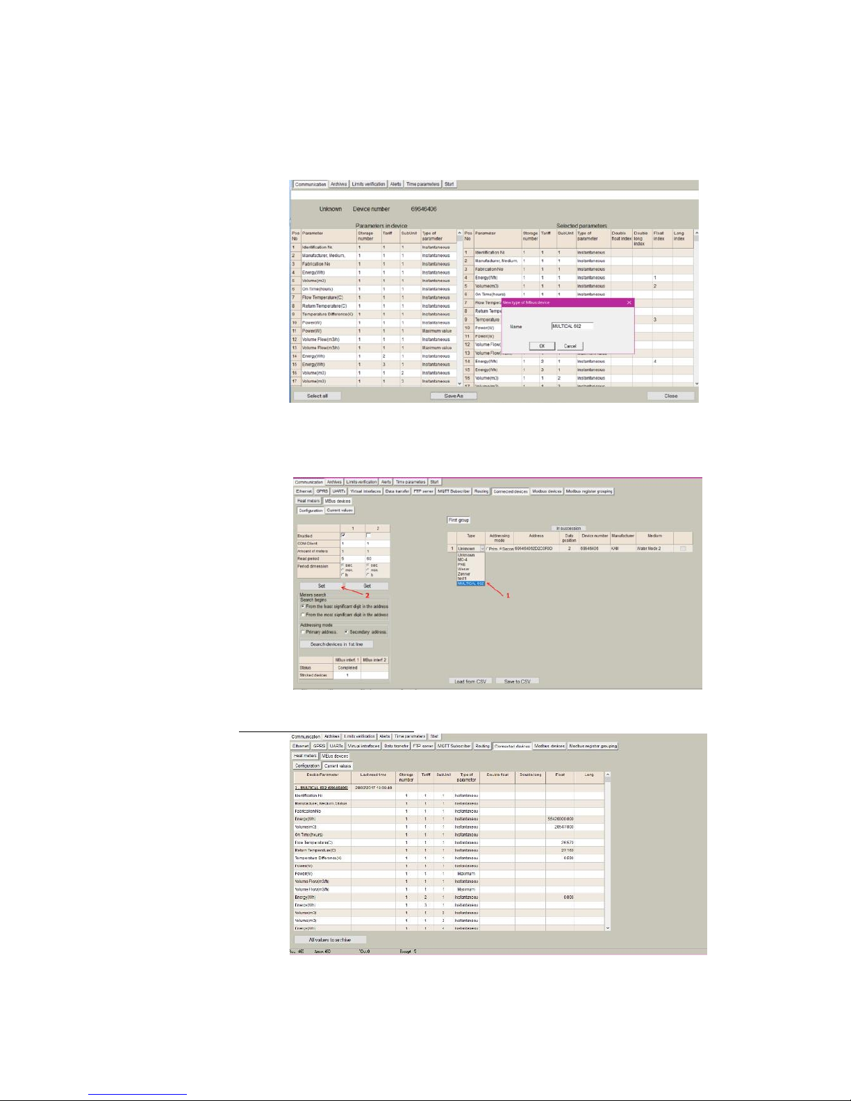
After indexing parameters, it is needed to save the configuration. Click on "Save
As" and give it a name so that user can reuse this configuration for similar meters
in the future
Figure 39. Saving the configuration.
Once the configuration is saved, it appears in the "Type" list. By clicking over the
list you can select the current online configurations. After making the selection,
click on SET:
Figure 40. Saved configurations
STEP 6: Check current values
Figure 41. Mbus Current values
Page 31

31
STEP 7: Configuring data logging
These data will be included into its corresponding MX-9 Modbus register. The
MX-9 has a Modbus array structure to store M-Bus parameters. Thus, in order to
collect specific parameters, user must select them by numbering within the array
as shown in previous steps. There are different arrays for different data format as
shown in the following table:
Registers
Mbus meters data (1...50)
Data format
R/W
1-st Mbus counter's data
24000
Status (0-not read, 0xffffread)
Int16
R
2400124002
Reading time (UNIX time)
Int32
R
2400324082
Double data[20]
F64
R
2408324098
Long data[4]
Int64
R
2409924158
Float data[30]
F32
R
2415924178
Int data[10]
Int32
R
2-nd Mbus counter's data
2417924357
... R
50-th Mbus counter's data
3277132949
... R
In the previous example, we have given float index “1” to “Energy(Wh)”
parameter. Thus, we will find it in Modbus register 24099 while “Fabrication
number” has been given double float index “1” being stored in Modbus register
24003.
This configuration can be saved by clicking on the “Save as” button.
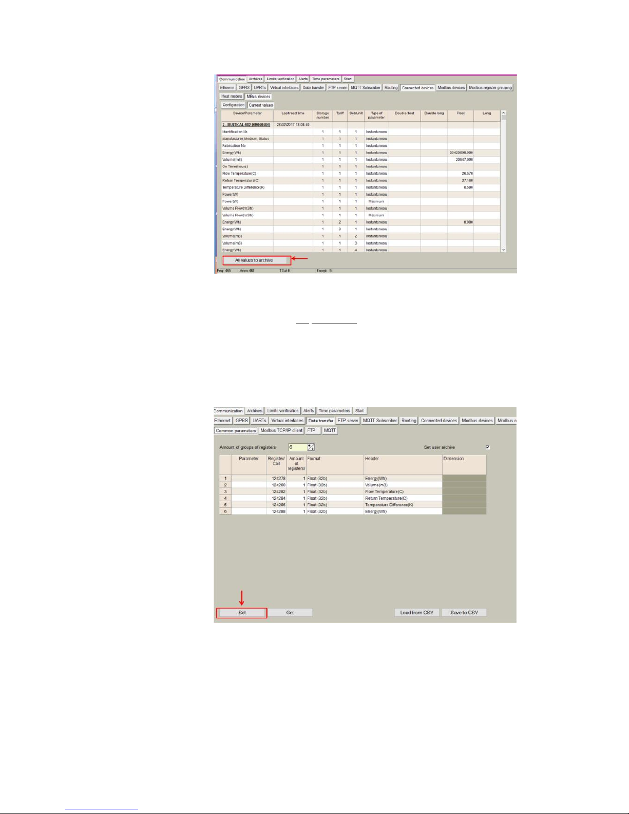
it is possible to send these data automatically to the user archive memory (for
datalogging) by clicking on "All values to archive"
Page 32
32
Figure 42. All values to user archive
NOTE: If there are some registers configured previously in "common parameters" to
be stored in the user archive they will be deleted by using this function. In case of
using user archive memory it is recommended to configure first the Mbus client
module.
After click in "All values to archive" all selected parameters will be automatically
configured in "Common parameters" list, which will be stored in "User archive".
In order to update changes, click in "SET" button".
Figure 43. Common parameters configuration for MBus
data storage
Page 33
33
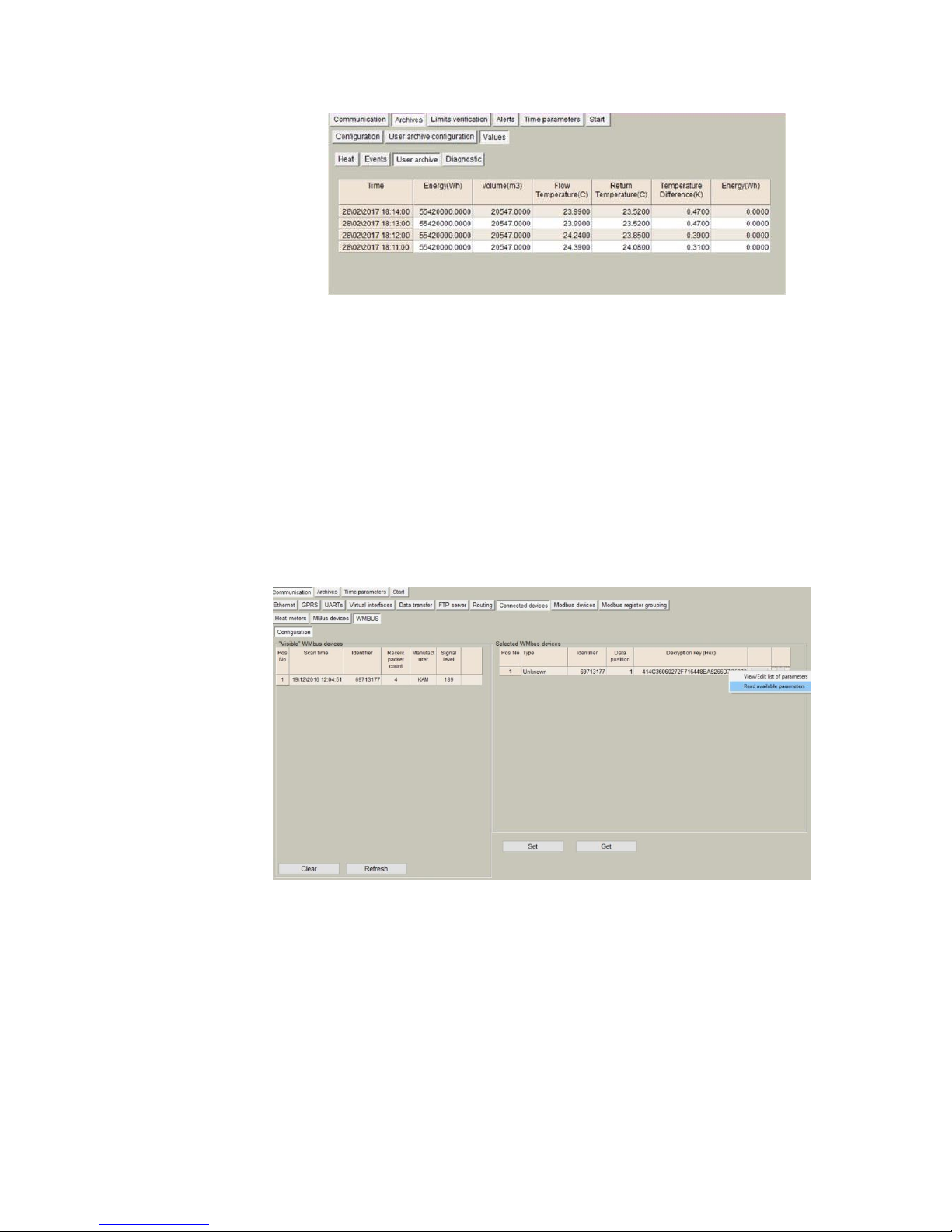
Figure 44. Mbus parameters in user archive module
5.9.2 Wireless M-Bus devices
The MX-9 automatically detects standard Wireless M-Bus devices. In the
following pages, a detailed description of each configuration step is done:
• Go to Communication > Connected devices > WMBUS > Configuration
and click on “Refresh” to scan wireless spectrum.
• Click on “+” to add each meter to the “Selected WMbus devices” list in
the right side frame.
• If your meter data is encrypted, enter decryption key and click on “Set”.
• Click on right button and select “Read available parameters”.
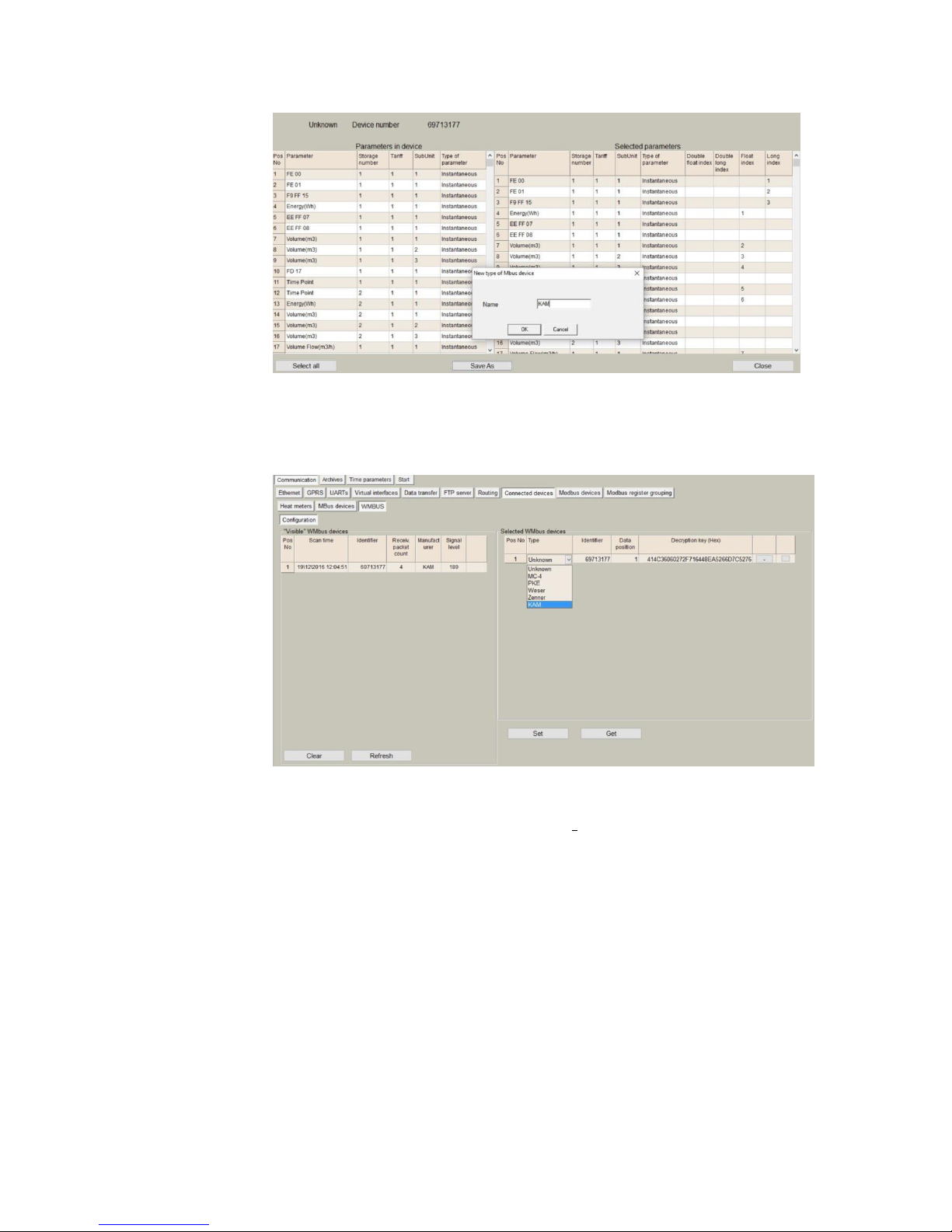
Figure 45. WMBus self-discovery
A list of parameters will be shown. User must select which parameters provided
by the WM-Bus devices should be stored in the internal MX-9 memory. Each
selected parameter must be configured with an ordering index according to the
data format that the meter presents in its datasheet. This index will order the
stored data in the internal memory map.
After indexing parameters, it is needed to save the configuration. Click on "Save
As" and give it a name so that user can reuse this configuration for similar meters
in the future
Page 34
34
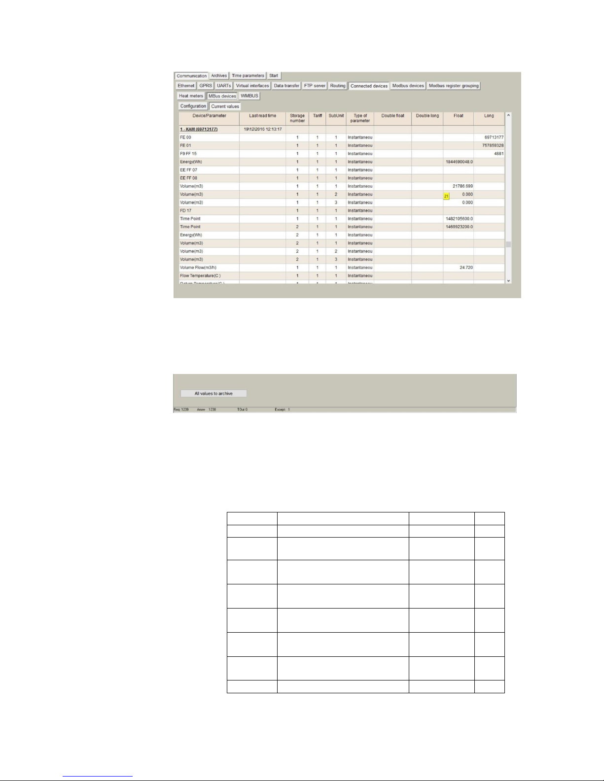
Figure 46. List of available parameters
Once the configuration is saved, it appears in the "Type" list. By clicking over the
list you can select the current online configurations. After making the selection,
click on SET:
Figure 47. Saved configurations
Next step is to check current values by going to Communication > Connected
devices > MBus devices > Current values
Page 35
35
Figure 48. Mbus Current values
After click in "All values to archive" all selected parameters will be automatically
configured in "Common parameters" list, which will be stored in "User archive".
To update changes, click in "SET" button".
Figure 49. Mbus registers to archive
Moreover, these data will be included into its corresponding MX-9 Modbus
register. As in MX series, the MX-9 has a Modbus array structure to store MBus parameters. Thus, in order to collect specific parameters, user must select
them by numbering within the array as shown in previous steps. There are
different arrays for different data format as shown in the following table:
Registers
Mbus meters data (1...50)
Data format
R/W
1-st Mbus counter's data
24000
Status (0-not read, 0xffffread)
Int16
R
2400124002
Reading time (UNIX time)
Int32
R
2400324082
Double data[20]
F64
R
2408324098
Long data[4]
Int64
R
2409924158
Float data[30]
F32
R
2415924178
Int data[10]
Int32
R
2-nd Mbus counter's data
Page 36

36
2417924357
... R
50-th Mbus counter's data
3277132949
... R
Page 37
37
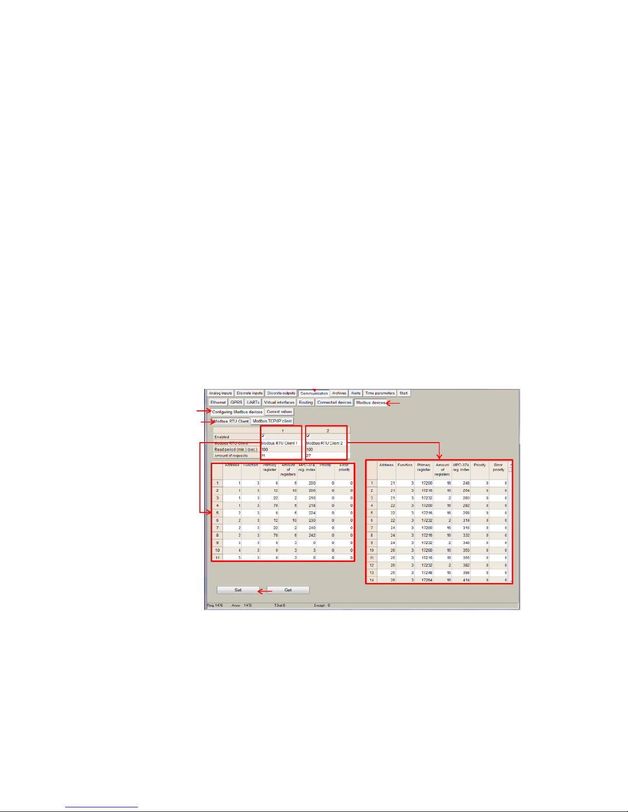
5.10 Communication > Modbus devices
There are two methods for reading Modbus devices connected to the MX-9.
By using the MODBUS RTU client to request data from MODBUS RTU devices:
Communication>Modbus devices>Configuring Modbus devices> Modbus RTU client
The MX-9 can read up to 50 Modbus RTU devices through each UART.
In order to configure Modbus RTU client list, follow the next steps:
Go to Communication>Virtual interfaces>Modbus Devices.
Once the virtual interface has been enabled under Modbus RTU client- ‘UART x’ ,
the list of requests for the Modbus client must be configured. For this purpose go to
Communication>Modbus devices>Configuring modbus devices> Modbus RTU
client .It must be configured as much lines as Modbus RTU requests required. The
number of requests can be configured in "Amount of requests", where:
"Address": Slave device Modbus Address.
"Function": Modbus RTU function.
"Registers/coils ":Register/s address to be requested.
"Amount of registers/coils": number of registers to be read from the register address
configured in “Register/coils”
MX- Reg. index: Internal MX-9’s RAM memory index where data is recorded. In case
of MX-9 it starts in the address 52000 (index =0 => RAM Modbus
address=52000@DEC).
Priority: It configures the request management priority.
Figure 50. “Modbus devices” tab. Modbus RTU client parameters
list configuration
NOTE: Maximum number of requests per each Modbus RTU Client is 50
NOTE: There exist 2 Modbus RTU clients. In case that both must work
together 2 different UARTs must be used, one per each Modbus RTU
client.
Page 38
38
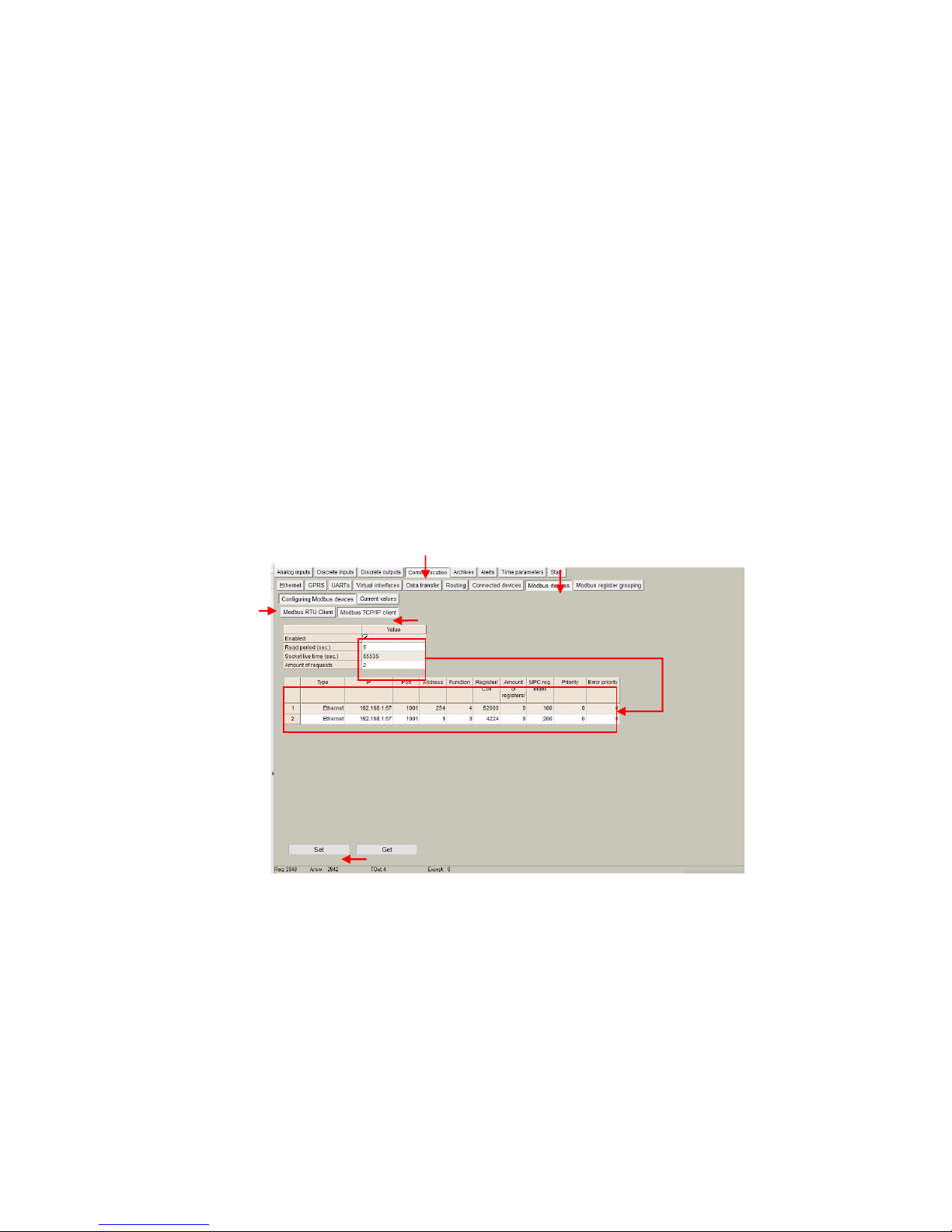
By using the Modbus TCP client to collect data from Modbus TCP devices:
Communication>Modbus devices>Configuring Modbus devices> Modbus TCP client
In order to configure Modbus TCP client list, follow the next steps:
Go to Communication>Virtual interfaces>Modbus Devices>Configuring Modbus
devices> Modbus TCP client.
User must configure as much lines as Modbus TCP requests required. The number
of requests can be configured in "Amount of requests", where:
Type: Ethernet/GPRS
IP: Slave Modbus TCP IP Address
Port: Slave Modbus TCP port
"Address": Slave device Modbus Address.
"Function": Modbus function (3,4,16,...).
"Registers/coils ": Register/s address to be requested.
"Amount of registers/coils": number of registers to be read from the register address
configured in “Register/coils”
MX- Reg. index: Internal MX-9’s RAM memory index where data is recorded. In case
of MX-9 it starts in the address 52000 (index =0 => RAM Modbus
address=52000@DEC).
Priority: It configures the request management priority.
NOTE: In order to remove any request previously set, write ‘0’ in its
“Address” column.
Figure 51. “Modbus devices” tab. Modbus TCP client parameters list
configuration
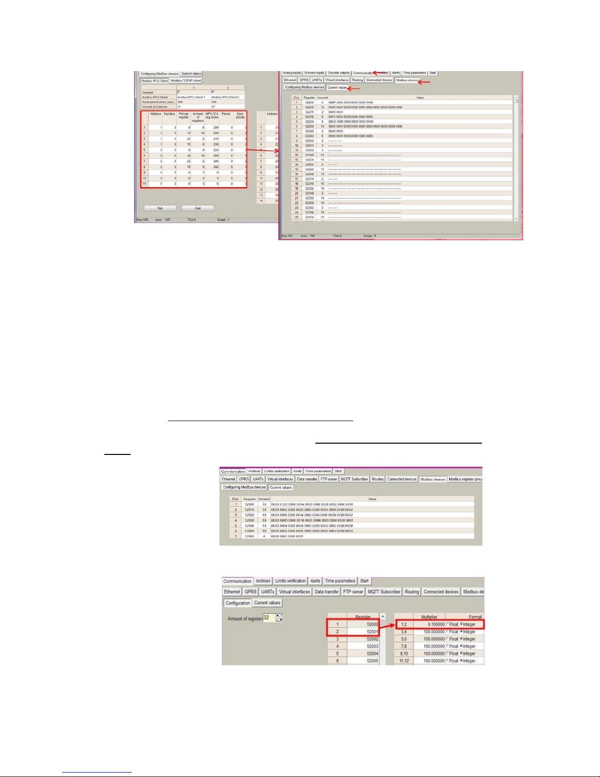
After any of the previous method has been configured, it is possible to check the received
information through the Modbus RTU/TCP client in “Current values” tab, also enabling
correct performance testing.
Page 39
39
Figure 52. “Modbus devices” tab. Current values
5.11 Communication > Modbus register grouping
It is also possible to apply data formats or conversions to the MX-9 Modbus registers.
For this purpose, go to Communication > Modbus register grouping > Configuration.
In this section, user can configure registers which data need to be converted somehow.
Following parameters need to be filled in:
"Amount of registers”: Number of MX-9 Modbus registers to be converted
“Multiplier”: Conversion factor to be applied to the Modbus register value
“Format”: Register data format.
NOTE: Format must be the Input register data format, not the format after conversion.
As an example, if register 52000-52001 corresponds to a pulse counter reading which data
format is “int 32”, “integer” option must be selected. Data converted is always stored in “float”
format.
Figura 53. Modbus Client Current values (Without conversion)
Figura 54.Configuring Modbus register grouping: Register,
Multiplier and data format
Page 40
40
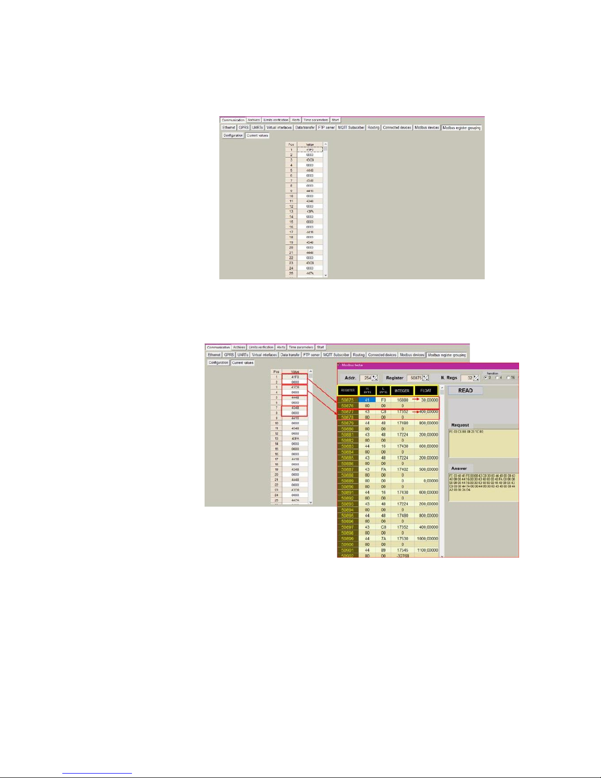
Once parameters are properly configured, user will be able to check if conversion is
correctly done by visiting Current values tab where float-formatted data will be shown in
hexadecimal notation.
Figure 55. Modbus register grouping current values
The Modbus registers converted by the Modbus register group functionality are storage
from the Modbus register: 50875:
Figure 56. Converted Data from Modbus register grouping
Page 41
41
6 "Archives" tab
The MX-9 has an internal 8MB flash memory. In case, the device is used as datalogger,
the following steps must be done:
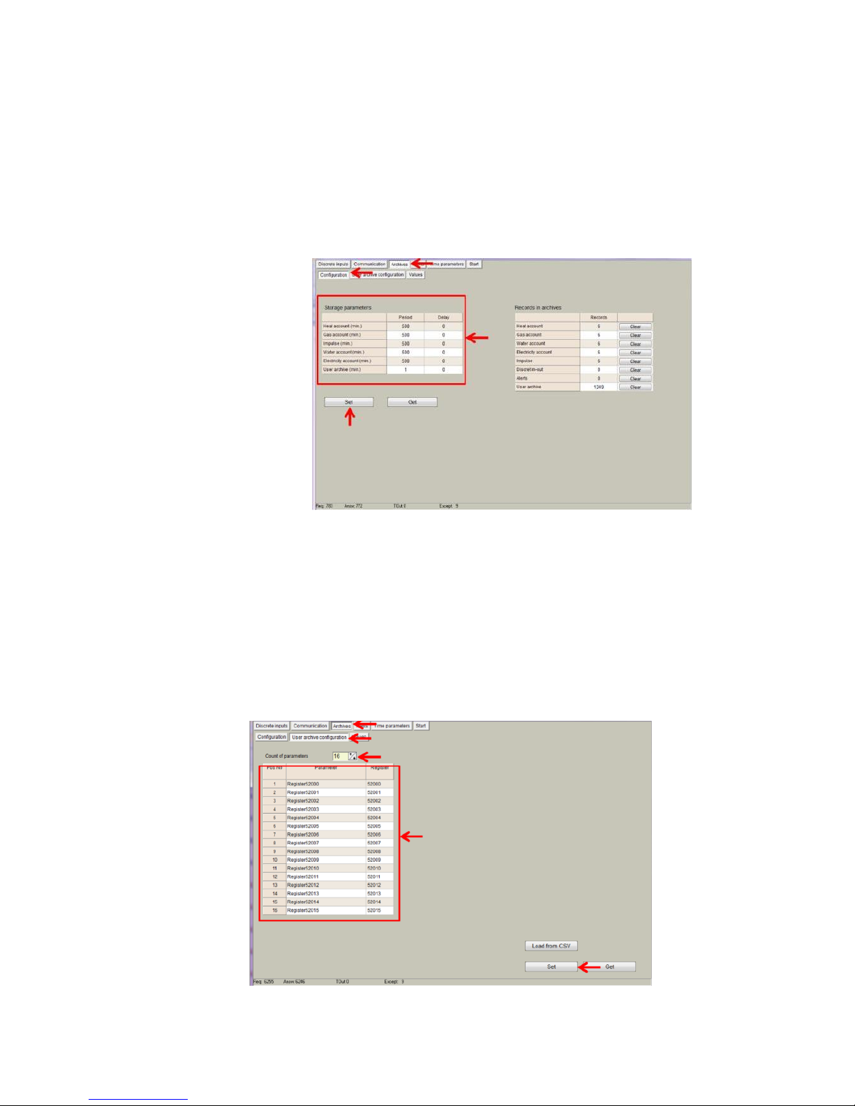
Go to Archives>Configuration
In "Storage parameters" frame, configure the following:
"Period": It defines storage interval. Internal memory is organized in different blocks
depending on the devices nature which are connected to the MX-9.
Figure 57. “Archives” tab. Storage frequency configuration
In case user needs to customize storage blocks, signals acquisition
must be configured accordingly. Memory block used will be defined
as "User Archive" (see next step).
Go to Archives>User Archive Configuration
Under this tab, user can configure datalogging following his own
requirements. In the next pages, a configuration example is given
by setting the following parameters:
“Count of parameters”: number of registers to be stored.
“Register”: Specific register to be stored.
NOTE: Timestamp is registered automatically.
Figure 58. “Archives” tab. User archive configuration
Page 42
42
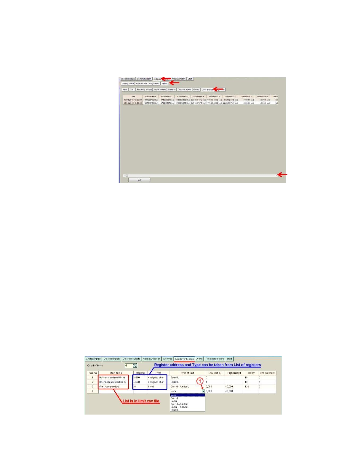
In order to check current data logged in the internal memory, go to Archives > Values >
User archive tab. This is only a test feature in order to ensure datalogging is performing
correctly.
Figure 59. “Archives” tab. User archive current values
NOTE: Internal datalogging memory is organized as a file system accessible through the
use of standard Modbus function 20 “File register".
7 "Limits verification" tab
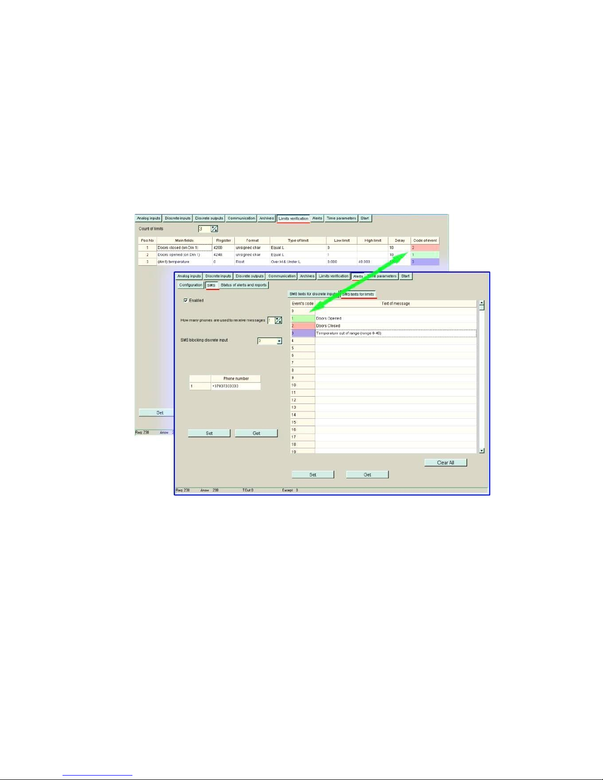
This tab enables users to set up limits verification raising events for issuing alerts when
condition is met. To create the list, follow the next steps:
1. Choose “Count of limits” in order to start creating the number of positions desired;
2. Choose “Type of limit” (this must to be done first) among the following options:
o Over H: event will be generated when the value is above the high limit. o
Under L: event will be generated when the value is below the low limit.
o Over H & Under L: event will be generated when the value is out of the
range between high and low limit.
o Under H & Over L: event will be generated when the value is within the
range between high and low limit.
o Equal L: event will be generated when the value is equal to the low limit.
3. Enter register number you want to control or choose from Main fields list (To create
and/or edit list of limit’s values use file limits.csv, that is in program’s folder.);
4. Enter data type, corresponding to data type of used register;
5. Choose limits;
6. Delay time (in seconds), if you want to filter accidental ar short time events;
7. Finally, add a code of event (value must to be from 0 to 99 and will be used for
alerts SMS/email/MQTT message sending)
Figure 60. “Limits verification” tab
Page 43
43
8 "Alerts" tab
MX-9 is able to send short SMS text messages, emails and MQTT messages based on
events generated by limits verification feature.
8.1 SMS Alerts on Limit verification
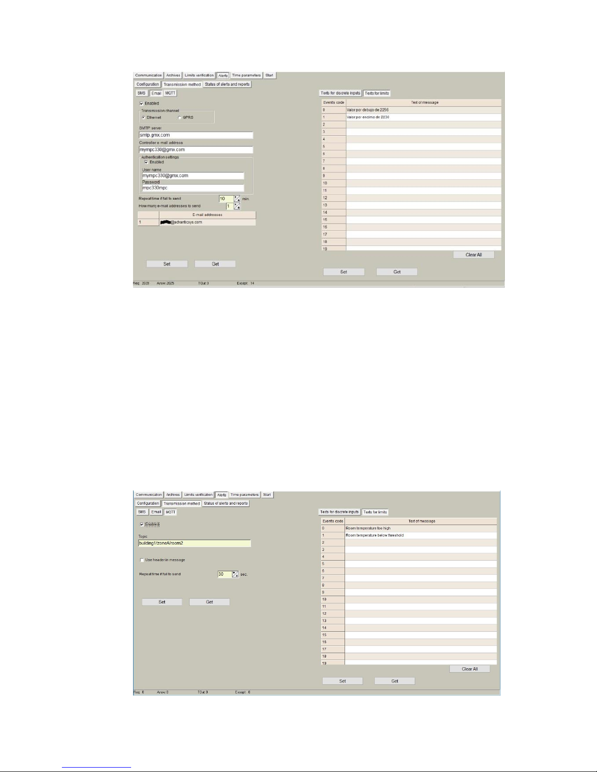
SMS alerts for limits is used for sending SMS alerts when alert conditions is set in “Limit
verification“ tab. Codes of events are used in this screen to configure alert messages as
shown in the following figure.
Figure 61. SMS alerts for limits configuration
8.2 Email Alerts on Limit verification
MX-9 can also send email alerts based on codes of events in a similar way it is explained
in previous chapter. In order to configure the email sending feature, the following
parameters must be set: SMTP server, e-mail address, user name and password. Finally,
user can configure up to 5 email accounts to which alerts will be sent.
Page 44
44
Figure 62. Email alerts for limits configuration
8.3 MQTT Alerts on Limit verification
Finally, MX-9 is able to send JSON formatted messages through MQTT protocol by
configuring the following parameters:
• "Enabled”: it is recommended to uncheck this box if this feature is not used.
• “Topic”: A topic is a UTF-8 string, which is used by the MQTT broker to filter messages
for each connected client. A topic consists of one or more topic levels. Each topic level
is separated by a forward slash (topic level separator).
• “Repeat time if failed”: if message is not properly received by broker, the device will
repeat it after seconds configured in this box.
Finally, if configuration is properly done, a message containing the “text of message” written
in the right column will be inserted into the JSON formatted message according to the event
code previously set.
Page 45
45
Figure 63. MQTT alerts for limits configuration
9 "Time parameters" tab
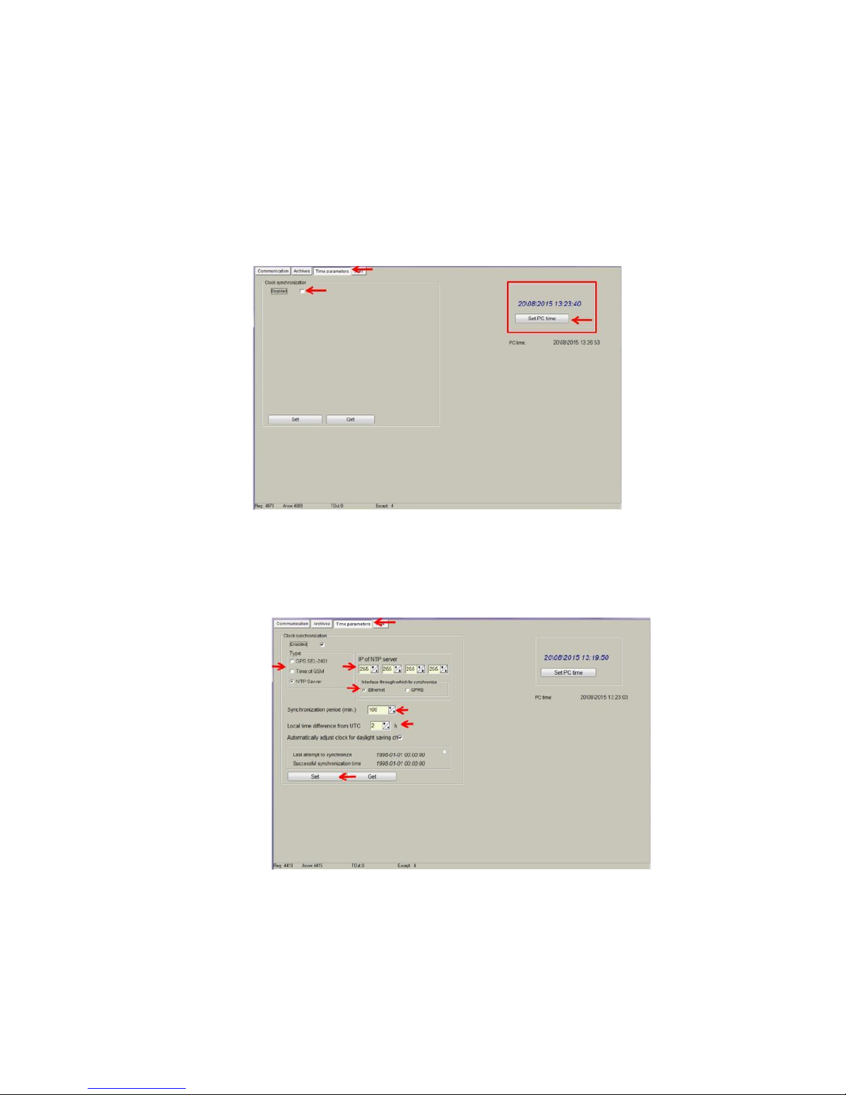
This tab enables users to set up time synchronization between MX-9 Real Time Clock (RTC)
and external time references. Several parameters can be configured under this tab:
• "Set PC time" It synchronizes internal RTC with PC time.
Figure 64. “Time Parameters” tab. Set PC time
• "Clock synchronization": It must be enabled if synchronization between MX-9 and any
Network Time Protocol (NTP) server is requested. This option is particularly accurate
since, every given period (“Synchronization period” parameter), device connects to an
NTP server to get current UTC time. Also automatic summertime is adjusted.
Figure 65. “Time Parameters” tab. NTP server configuration
Page 46

46
10 Abbreviations and explanations
• Xn – is a number of socket. This information are provided for manufacturer’s purpose
and used in data schemas and connection diagrams.
• GSM – Global Standart for Mobile Communications. This interfaces is prepared for
remote connections and data bidirectional data transfer over Global Standart Mobile
network.
• GPRS - a packet oriented mobile data service on the 2G and 3G cellular
communication system's global system for mobile communications (GSM).
• Ethernet - a family of computer networking technologies for local area networks (LANs)
commercially introduced in 1980. Standardized in IEEE 802.3, Ethernet has largely
replaced competing wired LAN technologies. This interfaces is prepared for connection
LAN (Local Area Network).
• IP address - An Internet Protocol (IP) address is a numerical label that is assigned
to devices participating in a network that uses the Internet Protocol for communication
between its nodes.
• TCP/IP – Transmission Control Protocol is for communication between computers,
used as a standard for transmitting data over networks and as the basis for standard
Internet protocols.
• MAC address –Media Access Control address is a unique identifier assigned to most
network adapters.
• UART – An Universal Asynchronous Receiver/Transmitter is a type of
“asynchronous receiver/transmitter, a part of computer hardware that translates data
between parallel an serial forms. UART are commonly used in conjunction with
communication standards such as EIA RS-232, RS-422 or RS-485. Record (UARTx)
on top of enclosure also are used as serial interface number.
• GND – ground wire contact
• RS232 - the traditional name for a series of standards for serial binary single-ended
data and control signals connecting between a DTE (Data Terminal Equipment) and a
DCE (Data Circuit-terminating Equipment). It is commonly used in computer serial
ports. The standard defines the electrical characteristics and timing of signals, the
meaning of signals, and the physical size and pin out of connectors. RS232 interfaces
are prepared for connection of pheripherical devices (example energy meters,
controllers, machines and etc.).
• TD – contact for transfer data wire of RS232 socket
• RD – contact for read data wire of RS232 socket
• DTR – contact for Data Transmit Ready wire of RS232 socket
• RS485 - standard defining the electrical characteristics of drivers and receivers for use
in balanced digital multipoint systems. The standard is published by the ANSI
Telecommunications Industry Association/Electronic Industries Alliance (TIA/EIA).
Digital communications networks implementing the EIA-485 standard can be used
effectively over long distances and in electrically noisy environments. Multiple receivers
may be connected to such a network in a linear, multi-drop configuration. RS485
interfaces are prepared for connection of pheripherical devices (example energy
meters, controllers, machines and etc.).
• A+ – contact for positive wire of RS485 socket
• B- –contact for negative wire of RS485 socket
• USB – Universal Serial Bus is an industry standard, that defines the cables,
connectors and protocols used for connection, communication and power supply
between computer and electronic devices. USB type B socket is prepared for
connection to PC(Personal Computer). USB type A socket is prepared for connection
to pheripherical devices (example memory stick’s and etc.).
• M-Bus - a European standard (EN 13757-2 physical and link layer, EN 13757-3
application layer) for the remote reading of gas or electricity meters. The M-Bus
interface is made for communication on two wire, making it very cost effective.
• MBUS+ – contact for M-Bus positive wire
Page 47

47
• MBUS- – contact fot M-Bus negative wire
• Socket – is an endpoint of a bidirectional inter-process communication flow across an
Internet Protocol-based computer network, such as the Internet.
• Data – contact for data wire
• Req – contact for request wire
• CL+ – contact for current loop positive wire
• CL- – contact for current loop negative wire
• Status – device status indicating LED
• Uoutput – status of power for external device indicating LED
• TX/RX – data transfer/receive indicating LED
• TXD – data transferring LED indicator
• RXD – data receiving LED indicator
• 100Mbs – Ethernet High speed connection indicating LED
• Central computer – server or a computer, where data can be sent.
11 Safety instructions
To install and setup device, special technical knowledges are needed. Call to seller or certified
professionals to connect and setup device !
Before connecting to power supply, be sure that:
1. Controller is not damaged (no cracks, melted, broken or exposed areas )
2. Controller is used with right and correct thickness cables.
3. Controller and antena are installed indoor.
4. The controller is intended for supply from a Limited Power Source (LPS) with current
rating of overcurrent protective device not greater than 2A
5. The highest transients on the DC secondary circuite of LPS, derived from AC main
supply, shall be less then 71V peak.
6. The associated equipments (AE): PC and PSU (LPS) shall comply with the
requirements of Standard EN 60950-1.
7. Controller is dry;
8. Ambient temperature and humidity is in normal range;
9. Other types of devices (counters, etc.) are connected correctly by using
manufacturer‘s regulations.
10. The end of stranded conductor shall not be consolidated by soft soldering and must to
be terminated
11. Device, PC and other pheripherical devices are strictly connected through one double
pole breaker (current break less than 5A and space between breaker contacts more
than 3mm.) Pole breaker has to be in building‘s wiring and in reachable place with
markings
Don‘t use:
1. Device under open water (in rain and if water are spalshing on controller or connected
devices;
2. Device if enclosure, connected cables, or other connected devices are damaged;
3. External Back-Up batterys for powering of controller.
Use device by manufacturer‘s regulations otherwise you can damage controller or other
devices. In that cace munufacturer‘s warranty could not be obtained.
If you suspect that device doesn‘t operate correctly or has visible violations, please
contact manufacturer or your distributor to check or run maintanance.
Manufacturer does not affect and is not responsible for GSM/GPRS/Internet operators‘
provided network service pricing and costs.
Page 48
48
12 Technical Data
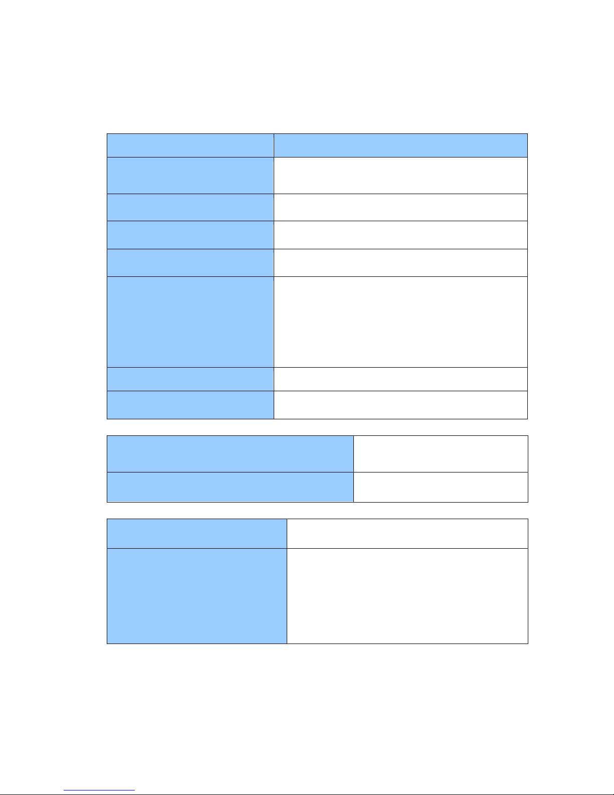
12.1 Communication interfaces
Interfaces
Technical data
RS485
Up to 1.2 km, max 32 transceivers, speed up to 57600
bps
RS232
Up to 15m, speed up to 57600 bps
M-Bus
Up to 8 devices
Wireless M-Bus
Up to 50 devices
GPRS
Transmission frequency bands: Quad-band 850, 900,
1800, 1900
Transmission Power:
Class 4 (2W) at GSM850 and EGSM 900
Class 1 (1W) at DCS1800 and PCS1900
Receiver sensitivity (typical) -109dBm, (Max) -107dBm
Modulation type: GSMK
Ethernet
10/100 Mb twisted pair, up to 100m
USB
Type B, version 2.0
12.2 Galvanic insulation
Insulation voltage between power supply and
second circuits
1500 V
Insulated interfaces
B, C
12.3 Indication
Indication type
LED’s
Indicated parameters
• •
•
•
Status of each Serial interface
GSM/GPRS modem status
GSM/GPRS modem transfer and receive
Ethernet Duplex mode status
•
Ethernet High speed connection status
•
Ethernet Transfer/Receive status
Page 49
49
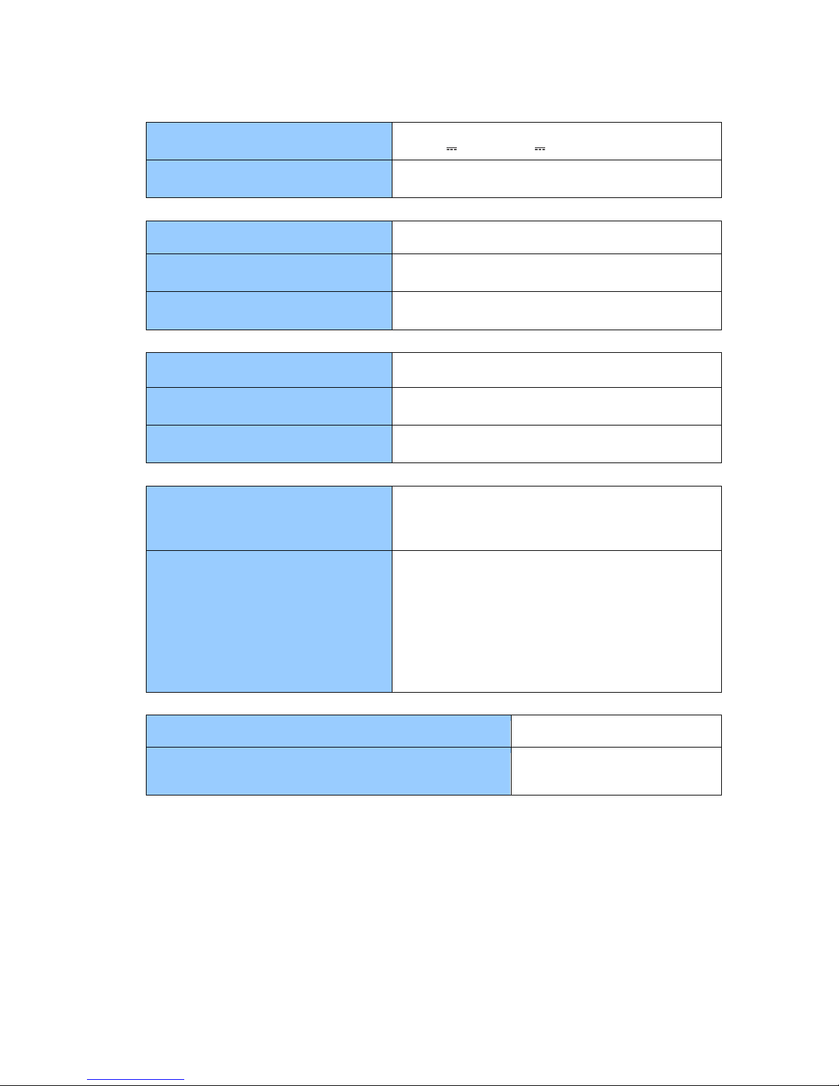
12.4 Power supply
Power supply
9 ÷ 36 V / 12 ÷ 50 V
Power consumption
300mA max
12.5 Construction
Mounting
DIN rail
Dimensions
147 mm x 128 mm x 50 mm
Tightness
IP20
12.6 Climate conditions
Operating temperature
From - 25 oC to + 60oC
Storage temperature
From - 40 oC to + 60oC
Relative humidity
From 5 % to 95 % non-condensing
12.7 Safety parameters
Safety requirements
Meets requirements:
LST EN 60950-1:2006
LST EN 60950-1:2006/A11:2009
Electromagnetic compatibility
Meets requirements:
EN 55022:2000+A1+AC:2002+A2:2003
EN 55024:2000+A1:2003+A2:2003
EN 61000-4-5:2002+A1:2003
EN 61000-4-6:2002+A1:2003
EN 61000-4-2+A1+A2:2002
EN 61000-4-3+A1:2004
EN 61000-4-4:2005
12.8 Other parameters
Storage memory
8 MB
Remote firmware loading
Yes. Through USB or/and
Ethernet and GSM/GPRS.
 Loading...