

Page 1
1
QUICK REFERENCE
To assist you with the installation and maintenance
service of your new spa, please ll out the following
information and keep it on hand for future reference.
Spa Information
Spa
Model:
Serial Number:
Dealership:
Dealer’s Phone Number:
Date Purchased:
Date Installed:
Contractor Information
General
1. Name:
Telephone:
2. Name:
Telephone:
Electrician
1. Name:
Telephone:
2. Name:
Telephone:
Concrete, Decking, and Masonry
1. Name:
Telephone:
2. Name:
Telephone:
Landscaping
1. Name:
Telephone:
2. Name:
Telephone:
2016 V&B Owners Manual.indd 1 3/3/2016 1:44:05 PM
Page 2

2
TABLE OF CONTENTS
Quick Reference:
Table of Contents:
Important Overview:
Safety Instructions:
Getting to Know Your Spa:
Equipment Compartment:
Filling Your Spa:
STIL/A Series Touch:
A Series Spas (A900):
R Series Spas (R600):
X Series Spas:
Jetpaks and Jets:
Water Care and Chemistry:
Spa Maintenance:
RCD Wiring Diagrams:
Display and Error Messages:
Troubleshooting Guide:
1
2
3
4
7
9
10
11
15
20
24
26
28
30
42
43
48
2016 V&B Owners Manual.indd 2 3/3/2016 1:44:05 PM
Page 3

3
IMPORTANT OVERVIEW
Congratulations on your purchase of a Villeroy & Boch Premium
Series, Comfort Series, Design Series, or X Series hot tub†.
NOTE: In this document, the terms “Spa” and “Hot Tub” are
used interchangeably. Take a moment to read this manual carefully
as you set up and use your new spa. Following the instructions in
this manual will ensure the safe, secure, and timely installation and
operation of your new spa.
Carefully read this Owner’s Manual before you install your spa.
Your Villeroy & Boch Limited Warranty will be void if damage
is caused by failure to install, maintain, and operate your spa in
accordance with the recommendations contained in this Owner’s
Manual or any other printed instruction, notice or bulletin from
Villeroy & Boch. Your spa’s serial number is located both on the
base under the equipment door and the Manufacturing ID Label
located inside the equipment compartment of your spa.
For the safety of all those who utilize your spa and its surroundings, please make sure your spa and any adjoining installations,
including the electrical hook-up, are completed only after acquiring any necessary approvals and permits from your local city and/
or country. Follow all local and national safety and wiring rules.
Some jurisdictions require certain fencing and/or self-closing and
self-latching gates to prevent accidental drowning in a pool or
spa. Your spa cover comes with a locking system which must be
utilized to ensure proper spa safety.
U.S. Patents: 7,908,684, 8,661,576, 8,881,321,
8,689,370, 8,869,469, 5,754,989, 5,987,663,
6,000,073, 6,092,246, 6,256,805, 6,543,067.
New Zealand Patent: 555112, 334,093
Australia Patent: 737,335
Canada Patents: 2,588,884, 2,260,237,
Other patents pending worldwide
† Villeroy & Boch are available in four dierent series
that include the following models:
Premium Series: A8, A8L, A8D, A7, A7L, A6L, &
A5L
Comfort Series: R8, R8L, R7, R7L, R6L & R5L
Design Series: S7L
X Series: X8, X8L, X7, X7L, X6L, X5L, & X6R
Villeroy & Boch reserves the right to change features,
specications & design without notication and
without incurring any obligation
2016 V&B Owners Manual.indd 3 3/3/2016 1:44:54 PM
Page 4

4
IMPORTANT SAFETY INSTRUCTIONS
Safety Instructions
When installing and using this electrical equipment, basic safety
precautions should always be followed, including the following:
1. Read and follow all instructions:
2. WARNING: To reduce the risk of injury, do not permit children to
use this product unless closely supervised at all times.
3. A wire connector is provided on this unit to connect a solid copper
conductor between this unit and any metal equipment, metal enclosures
of electrical equipment, metal water pipe, or conduit within 1.5m of the
unit.
4. WARNING: For products provided with a cord-connected,
ground-fault circuit-interrupter, the RCD must be tested before each
use. If the RCD fails to operate properly, disconnect the power until
the fault has been identied and corrected.
5. DANGER: Risk of Accidental Drowning. Extreme caution must be
exercised to prevent unauthorized access by children. To avoid
accidents, ensure that children cannot use this spa unless they are
supervised at all times.
6. DANGER: Risk of Injury. e suction ttings in the spa are sized
to match the specic water ow created by the pump. Should the need
arise to replace the suction ttings or the pump, be sure that the ow
rates are compatible. Never operate the spa if the suction ttings are
broken or missing. Do not replace a suction tting with one rated less
than the ow rate marked on the original suction tting.
7. DANGER: Risk of Electric Shock. Install spa at least 1.5m from all
metal surfaces. A spa may be installed within 1.5m of metal surfaces if
each metal surface is permanently connected by a minimum of 8.4mm2
solid copper conductor to the wire connector on the terminal box that is
provided for this purpose.
8. DANGER: R isk of Electric Shock. Do not permit any electrical
appliances, such as a light, telephone, radio, or television within 1.5m of the
spa. ese units DO NOT have an integral ground fault circuit interrupter.
e installation of an integral ground fault circuit interrupter MUST be
completed by a qualied Electrician and must meet all applicable electrical
codes.
9. WARNING: To Reduce the Risk of Injury:
a. Water temperature in a spa should never exceed 40
˚
C. Water
temperatures bet ween 38˚C and 40˚C are considered safe for a
healthy adult. Water temperature in excess of 40˚C may be injurious
to your health. Lower temperatures are recommended for young
children and/or when spa use exceeds 10 minutes.
b. Since excessive water temperatures have a high potential for causing
fetal damage during the early months of pregnancy, pregnant, or
possibly pregnant, women should limit spa usage when temperatures
are in excess of 38˚ C.
c. Before entering the spa, measure the water temperature with an
accurate thermometer since the tolerance of water temperature
regulating devices varies.
d. e use of alcohol, drugs, or medication before or during spa use may
lead to unconsciousness with the possibility of drowning.
e. Persons suering from obesity or a medical history of heart disease,
low or high blood pressure, circulatory system problems, and/or
diabetes should consult a physician before using a spa.
f. Persons using medication should consult a physician before using a spa.
Some medications may induce drowsiness while other medication may
aect heart rate, blood pressure, and/or circulation.
10. WARNING: PEOPLE WITH INFECTIOUS DISEASES
SHOULD NOT USE A SPA OR HOT TUB.
11. WARNING: TO AVOID INJURY, EXERCISE CARE WHEN
ENTERING OR EXITING THE SPA OR HOT TUB.
12. WARNING: DO NOT USE A SPA OR HOT TUB
IMMEDIATELY FOLLOWING STRENUOUS EXERCISE.
13. WARNING: PROLONGED IMMERSION IN A SPA OR
HOT TUB MAY BE INJURIOUS TO YOUR HEALTH.
14. CAUTION: MAINTAIN WATER CHEMISTRY IN
ACCORDANCE WITH MANUFACTURER’S INSTRUCTION.
15. CAUTION: TEST THE RCD BEFORE EACH USE OF THE
SPA .
16. CAUTION: ADEQUATE DRAINAGE MUST BE PROVIDED IF
THE EQUIPMENT IS TO BE INSTALLED IN A PIT O R I NDOO RS.
17. WARNING: Risk of Fatal Hyperthermia. Hyperthermia occurs
when the internal temperature of the body reaches a level several degrees
above the normal body temperature of 37˚ C. e symptoms of
Hyperthermia include dizziness, lethargy, drowsiness, and fainting. e
use of alcohol, drugs, and/or medication can greatly increase the risk of
fatal Hyperthermia. e eects of Hyperthermia include:
• Unawareness of impending hazard
• Failure to perceive heat
• Failure to recognize the need to exit the spa
• Physical inability to exit the spa
• Fetal damage in pregnant women
• Unconsciousness and danger of drowning
18. WARNING: Risk of Children Drowning. Your spa cover is not
rated as a safety cover. It is always wise to keep the spa cover securely
fastened when not in use. is will help discourage children from
attempting to enter the spa unsupervised.
19. WARNING: Risk of Drowning. Use caution when bathing alone.
Overexposure may cause nausea, dizziness, and fainting.
20. CAUTION: Risk of Injury. Young children should be supervised so
that they do not play with the appliance.
21. WARNING: Risk of Injury: To avoid injury, exercise care when
entering or exiting the spa. Surfaces can be slippery when wet. Do not
step or sit on headrests or FilterCap
™
. Also, keep all breakable objects
away from the spa area.
22. WARNING: Risk of Injury: Short-term inhalation of high
concentrations of ozone and long-term inhalation of low concentrations
of ozone can cause serious physiological eects.
23. CAUTION: Unauthorized Access. Secure the spa area against
unauthorized access. Make sure all spa barriers (fences, enclosures, etc.)
meet all applicable national and local codes. Keep spa cover on and
locked when it is not being used.
24. CAUTION: Risk of Damage to Spa or Equipment. By performing
maintenance as described in this manual, the chance of damage to your
spa and its equipment will be reduced. Never block the air vents that
lead to the spa’s equipment compartment, doing so may cause the spa to
overheat.
25. WARNING: Risk of Electric Shock or Death. Do not operate spa
during severe weather conditions (e.g. lightning, storms, etc.).
26. CAUTION: Non-Approved Accessories. Using accessories not
approved by Villeroy & Boch could void your warranty or cause other
problems. Please consult your authorized Villeroy & Boch Spa
dea ler.
2016 V&B Owners Manual.indd 4 3/3/2016 1:45:02 PM
Page 5

5
27. CAUTION: Location of Your Spa. Locate your spa on a foundation
that can support the maximum lled weight of your spa along with the
weight of all the occupants
using the spa (see Site Selection and
Preparation). Also, locate your spa in an environment that can
withstand repeated exposure to water and the possibility of a major
spill.
28. CAUTION: Cordage shall be replaced only with a special cordage
assembly available from the Manufacturer, its Service Agent, or
similarly qualied persons in order to avoid a hazard.
29. WARNING: is appliance is not intended for use by young
children or inrm persons without supervision.
30. WARNING: Before obtaining access to supply terminals, all supply
circuits must be disconnected.
31. WARNING: Risk of Injury or Accidental Drowning: Do not use
spa without lters and FilterCaps™ installed. e lters and FilterCap
serve as a barrier against bodily entrapment against the lter suction
tti ng (s).
32. WARNING: Risk to Infants, Elderly, and Women Planning
or Experiencing Pregnancy. Please consult your physician if the
above applies to you or anyone using the spa.
2016 V&B Owners Manual.indd 5 3/3/2016 1:45:02 PM
Page 6

6
2016 V&B Owners Manual.indd 6 3/3/2016 1:45:09 PM
Page 7
7
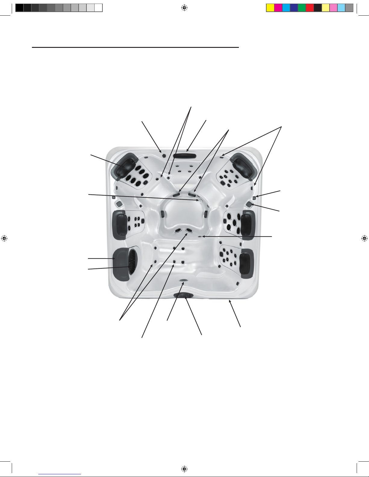
GETTING TO KNOW YOUR SPA
Spa Overview
[A7L Pictured]
Comfort Pillow
Water Feature Control Valve
Hip & Wrist Jets
Water Feature
Suction Fitting
Stereo Speakers (Optional)
Auxilliary Control Pad
(A Series Only)
Lighted Cup holder
(A Series Only)
Ozone Jet
Equipment Compartment
Control Pad
Light
Calf Jets
Floor Jets
SnapCap
Drain
Filter SnapCap
Weir Door/Filter Plate
2016 V&B Owners Manual.indd 7 3/3/2016 1:45:20 PM
Page 8
8
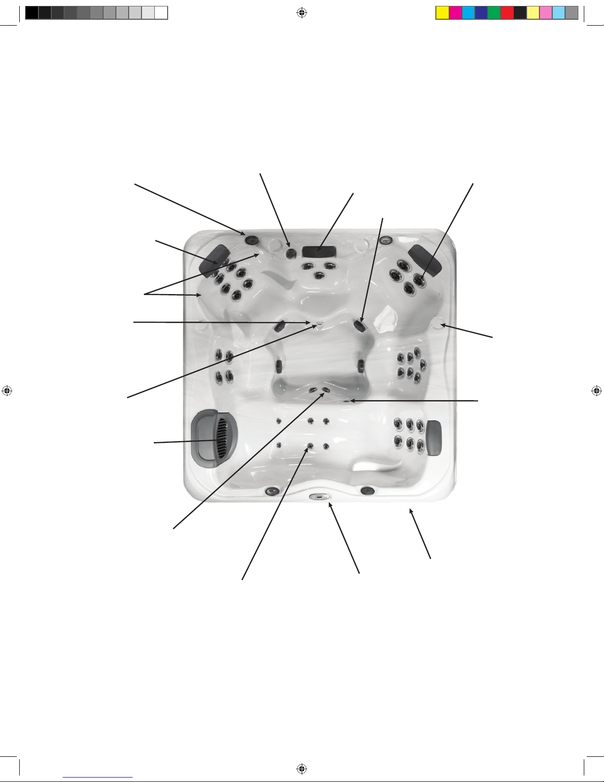
Spa Overview
[X Pictured]
Comfort Pillow
Water Feature Control Valve
Therapy Jets
Water Feature
Suction Fitting
Stereo Speakers
(Optional)
Cup Holder
Ozone Jet
Equipment Compartment
Control Pad
Light
Calf Jets
Foot Jets
Perimeter Lights
Drain
Weir Door/Filter Plate
2016 V&B Owners Manual.indd 8 3/3/2016 1:45:27 PM
Page 9
9
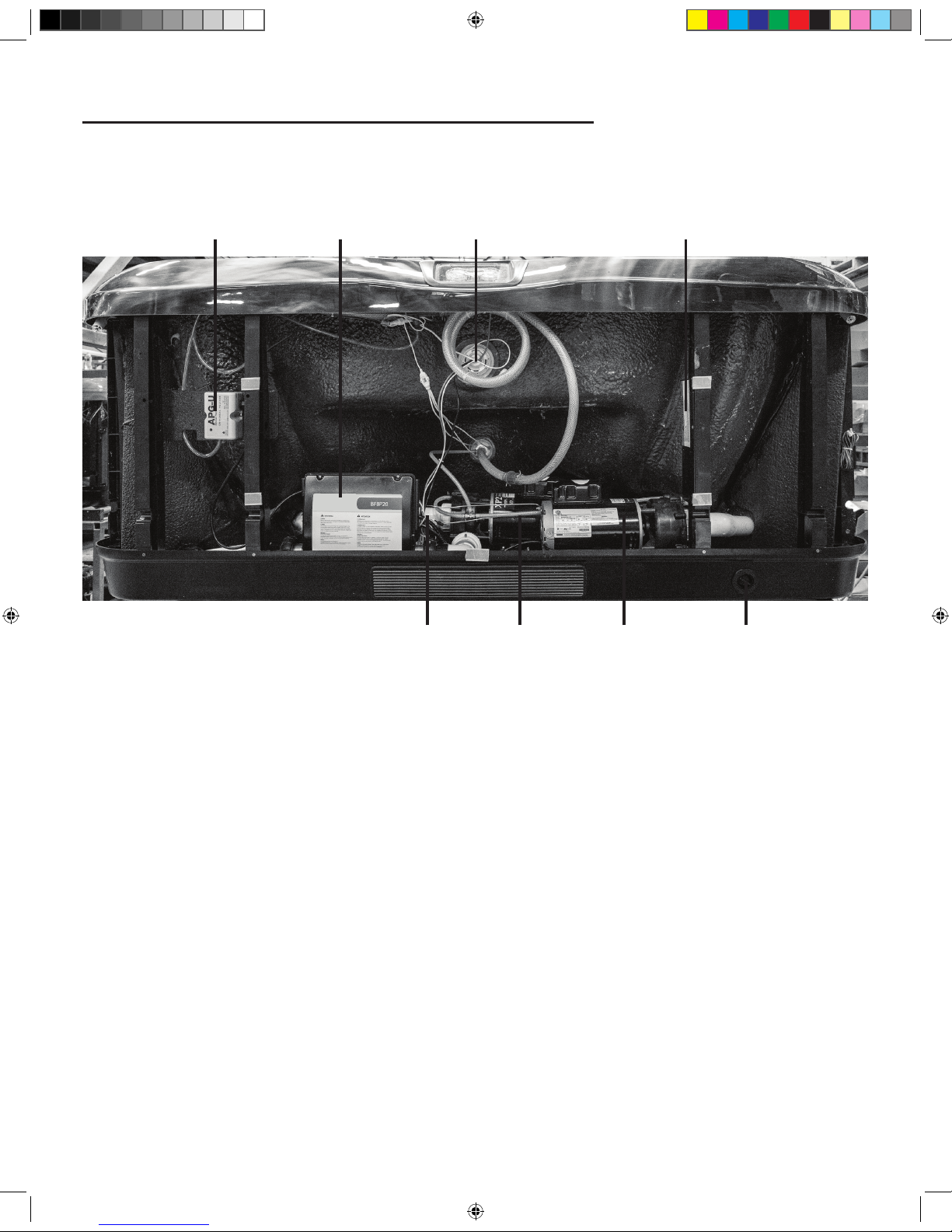
EQUIPMENT COMPARTMENT
Ozone* Control Center Light
Water Heater Pump 1 Pump 2 Drain Outlet
Safety Certificate
*Optional
2016 V&B Owners Manual.indd 9 3/3/2016 1:45:31 PM
Page 10
10
WARNING:
An empty spa (spa without water in it) must not
be left exposed to sunlight as shell damage may occur. Once the spa
is unwrapped, ll spa with water immediately or shade the spa with
cover or wrapping to prevent direct exposure to sunlight.
IMPORTANT: Do not turn power on to the spa without water
in the spa. Serious damage to the pump and heater may occur.
Step 1: Fill the Spa: Use a garden hose to ll the spa to the water
level indication mark on the faceplate of the lter weir assembly.
Be sure to open all valves and jets in the plumbing system before
lling to allow as much air as possible to escape from the plumbing
during the lling process.
NOTE: For complete lling instructions, refer to Changing Spa
Water (page 30).
IMPORTANT: Never ll the spa with soft water unless an
appropriate mineral supplement is immediately added (see your
authorized Villeroy & Boch Dealer). If your water is extremely
hard, it is preferable to either dilute the water’s hardness by
blending the water with water from a water softener, or by the
addition of a special water softening chemical (see your authorized
Villeroy & Boch Dealer).
Step 2: Check for Leaks: After the spa is lled, check all ttings
and equipment in equipment compartment for signs of leakage
before turning on the spa. Turn on pump(s), once again, check for
leakage. If a leak is detected, tighten the tting by hand. If the leak
persists contact your authorized Villeroy & Boch Dealer.
Step 3: Install Cover: e spa cover comes with tie down
straps and locking hardware that attaches the cover to the spa or
decking. If your dealer did not install the cover, refer to the Cover
Installation Instructions included with the cover.
Cover locks are an essential component for compliance with the
safety standard for spa covers.
Control System
IMPORTANT : Your Villeroy & Boch Spa is equipped with
one of 4 types of control pads: A900 (5 Button), R600 (5 or 6
Button), X300 (3 or 4 Button)or Touch Screen. Locate the control
system on your spa by matching it with the photo provided under
each control panel section and follow the specic instructions for
operation of your specic control system.
Your spa is pre-programmed with default lter cycles and
temperature settings. e following control panel instructions will
detail the procedures to alter such default settings.
FILLING YOUR SPA
2016 V&B Owners Manual.indd 10 3/3/2016 1:45:32 PM
Page 11

11
Preparation
To operate:
Ensure the spa is lled to its
correct operating level. After
turning the power on at the
main power panel, the control
panel will display a splash,
or startup screen. As you
begin to operate the control, push each icon (button) slowly and
deliberately with your nger.
Priming the Pumps
As soon as the spa has power, it will enter “Priming Mode.” If
your spa is equipped with two pumps, two icons will appear in the
touch screen. Press
“Prime Jets” button once to start Pump
1 in low-speed, and then a second time to set it to high speed. If
your spa is equipped with a second pump, follow the procedure
again for that pump. All pumps should be running in at their
highestspeed to facilitate priming.
IMPORTANT: A pump should not be allowed to run
without priming (water owing out of the jets) for more than 2
minutes. Under NO circumstances should a pump be allowed to
run without priming beyond the end of the 4-5 minute priming
mode. Doing so may cause damage to the pump and cause the
system to energize the heater and go into an overheat condition.
NOTE: Turning the power o and back on again will initiate a
new pump priming session. Sometimes momentarily turning the
pump o and on will help it to prime. Do not do this more than 5
times. If the pump(s) will not prime, shut o the power to the spa
and call for service. Once the system has exited Priming Mode,
the control panel will display the Main Screen. e temperature
will not be displayed but will show four dashes as pictured below.
e system requires approximately 1-2 minutes of water owing
through the heater to determine and display the correct water
temperature.
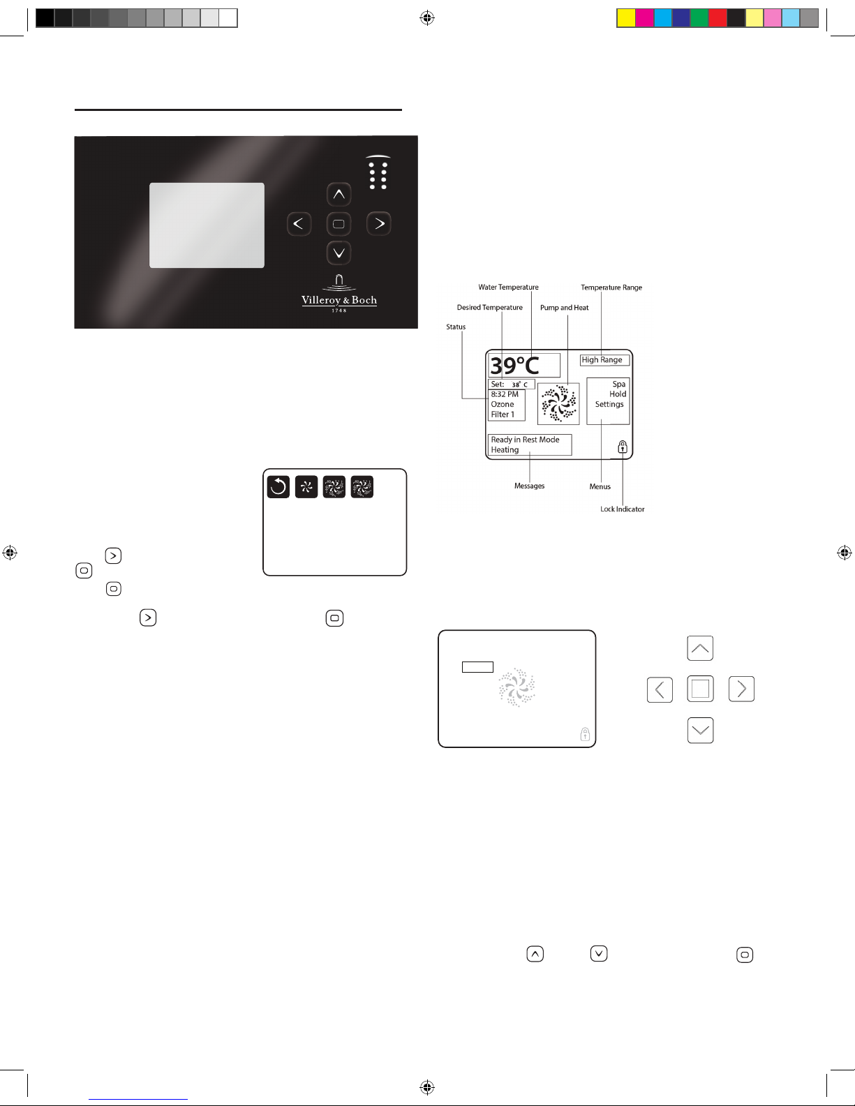
The Main Screen
Important information about spa operation can be seen quickly
from the main screen. Push icon from any screen to return to
the main menu.
2:15pm
0
3
IR
39
°
The Settings Screen
e “Settings” screen is accessed by pressing the icon. e
Settings menu is where spa settings and programming are
controlled.
Settings
Heat
Lock Filter
Time Reminders
Light Settings
Temp Settings
To adjust the temperature of your spa, use the up and down
arrows on the main screen. Set temperature will temporarily
display when setting. Actual water temperature will return to
the display several seconds after you are nished adjusting the set
temperature, and water has been running through the pumps.
Dual Temperature Range
Your spa comes equipped with two pre-programmed temperature
ranges, High and Low. When a temperature range is selected, the
spa will heat to the temperature associated with that range and
remain at that temperature. High Range can be set between 80°F
(26.7°C) and 104°F (40°C). Low Range can be set between 50°F
(10°C) and 99°F (37.2°C). e most common use for the low
range is during vacations or extended periods of inactivity. Freeze
Protection is active in either range.
DESIGN & PREMIUM TOUCH SPAS
2016 V&B Owners Manual.indd 11 3/3/2016 1:45:36 PM
Page 12
12
Heat Mode Ready vs. Rest
When in “Ready” mode, the pump that circulates water through
the heater (heater pump)will turn on every 1/2 hour to measure
water temperature, heat if needed, and refresh the temperature
display. When in Ready mode your spa will continually maintain
its set temperature.
“Rest” mode is an economy mode in which the spa only
circulates and heats water during designated lter cycles. As a
result, in the time period between ltration cycles the control may
not display the correct water temperature unless the heater pump
is on and has been running for up to two minutes. When in
Rest mode your spa will heat to its set temperature twice per day
during programmed lter cycles.
Ready-in-Rest Mode
When the spa is in Rest mode and a “Jet” button is manually
pressed, the spa will enter Ready-in-Rest mode and heat up to
the selected temperature, allowing for use in periods outside of
scheduled lter cycles.
Light Settings
The spa lights are activated by pressing the icon. Pressing
this icon turns o or on your interior or exterior lights manually.
By turning the light o and then on again, you can choose the
light color and display properties. Each time the light is turned
o and on it will advance according to the following sequence:
1. Color wheel: Color changes quickly through available
solid colors.
2. Color fade: Colors fade through spectrum A colors.
3. Random Color Change: Random color changes occur in
quick succession.
4. Spectrum fade: Colors fade through spectrum B colors.
5. Solid Color: Red
6. Solid Color: Green
7. Solid Color: Blue
8. Solid Color: Yellow
9. Solid Color: Indigo
10. Solid Color: Orange
11. Solid Color: Violet
12. Solid Color: White
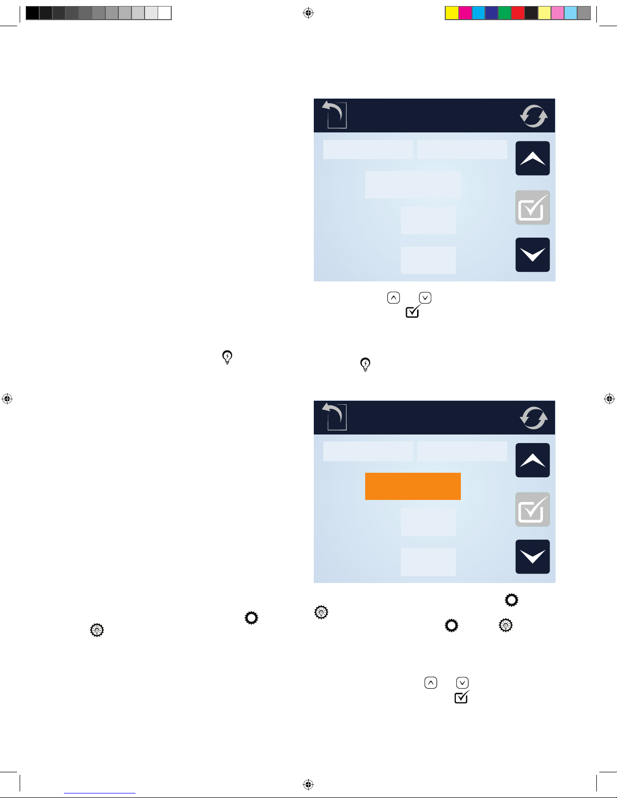
Light Settings (Premium Series)
Premium Series spas come equipped with a light timer.
To set the light timer, from the main menu, select
and then
. To enable the timer, press the [Disabled]
icon. Set the desired time and duration or the timer by
pressing on the pad above the time you wish to adjust
Light Settings
Interior
Light Timer
Exterior
Start
End
10:45 am
10:45 am
and then using the and icons to choose the desired time
and duration. Press the
icon to conrm your selections.
Light Settings (Design Series)
Design Series spas come equipped with the ability to
independently control the interior and exterior lights with a light
timer. e
button on the main control screen will operate
the interior and exterior lights according to setting designated in
the Light Settings screen.
Light Settings
Interior
Light Timer
Exterior
Start
End
10:45 am
10:45 am
To set the light timer, from the main menu, select and then
. To change the interior/exterior setting or to set the light
timer, from the main menu, select
and then
To engage the interior lights press the Interior button. To engage
the exterior lights press the Exterior button. To enable the timer,
press the [Disabled] icon. Set the desired time and duration
or the timer by pressing on the pad above the time you wish
to adjust and then using the
and icons to choose the
desired time and duration. Press the
icon to conrm your
selections. e light timer will turn on the interior and exterior
lights according to the current Interior and Exterior button
positions.
2016 V&B Owners Manual.indd 12 3/3/2016 1:45:39 PM
Page 13

13
Time Settings
Setting the time of day
Setting the time is important for ltration settings and other
background settings to function as expected. To set the time, from
the main menu, press the
icon, followed by the icon.
is will bring you to the “Time of Day” menu. Select the correct
time by pressing on the hour or minutes, and then using the
and buttons to select the correct time. Holding the or
buttons will allow you to more quickly move through time.
Press the icon to conrm your changes.
Filtration Cycles
Your Spa comes factory programmed to run two cycles in each 24
hour period.
Filter Cycle 1: Begins at 6:00pm (18:00) and runs for 2
hours. (3 hours for spas equipped with the optional WellSpring
Filtration Pump.)
Filter Cycle 2: Begins at 8:00am (8:00) and runs for 1 hour.
ese factory set ltration cycles should be adequate for light to
normal spa use (spas used once to twice per week). For cases of
more frequent to heavy spa usage, you may need to increase the
lter cycle durations to maintain water clarity.
Changing Filter Cycles:
To change lter 1 cycle:
From the main menu, press “Settings” followed by . is
will take you to the “Filtration” menu. Select the “Filter Cycle 1”
by pressing [1]. Adjust the time and duration by pressing on the
hour or minutes, and then using the
and buttons to select
the correct time and duration. Press the
icon to conrm your
changes.
To change lter 2 cycle:
Select the “Filter Cycle 2” by pressing [2]. Adjust the time and
duration by pressing on the hour or minutes, and then using the
and buttons to select the correct time and duration. Press
the icon to conrm your changes.
Purge Cycles
In order to maintain sanitary conditions and protect against
freezing, your spas pumps will purge water from their respective
plumbing by running all pumps at the beginning of each lter
cycle. If the Filter Cycle 1 is set for 24 hours, enabling Filter
Cycle 2 will initiate a purge when Filter Cycle 2 is scheduled to
begin.
To Change Preferences
To change temperature display between Fahrenheit (F) and
Celsius (C), 24 or 12 hour clock :
From the main menu, press . In the Settings menu press the
key to move to the second page of the menu. Press the
icon. e “Units” menu will then be displayed. To change the
temperature setting, press the temperature unit which is currently
displayed. is will change it from C° to F° or vice versa.
To change the time display press on the currently selected hour
unit.
To Set Reminders
From the main menu, press , then in the “Settings” menu,
press the
icon. Next, press the portion of the panel where
“Yes” or “No” is displayed. is will toggle the reminders to
trigger, or turn them o.
Hold
e “Hold” function prevents the jets from running to allow
JetPaks to be swapped out. By default, a hold lasts 60 minutes, or
until the button is pressed.
Restricting Operation
e control panel can be restricted to prevent unwanted use or
temperature adjustments. “Panel Lock” prevents most functions
on the controller from being used, while all automatic functions
remain active. “Lock Settings” in contrast, allows the jets and
lighting to be adjusted, while other features are inactive.
To lock the settings, from the Main Menu
Press , followed by . e “Settings” lock and ”Panel” lock
options will be displayed in the menu. Press
to lock the
settings in their current conguration, or
to lock the panel.
While the panel is locked, the only buttons that will function are
the buttons that lead to the locking screen.
To cancel either of the lock settings, navigate to the Lock menu
by pressing followed by . Press the corresponding icon
to release the lock.
Invert Display
To inver the display, from any screen press the icon.
Fault Log
To access the fault log, press . In the Settings menu press the
key to move to the second page of the menu. Press the
icon. In the Utilities menu, press the icon. Events recorded
in the log can be accessed by pressing or buttons.
Panel Sleep
Your touch panel comes pre-programmed to go to sleep after
30 minutes of disuse. To change this setting, press
. In the
Settings menu press the key to move to the second page of
the menu. Press the
icon to enter the Utilities menu. Press
the
icon. You can adjust the length of time before your
panel goes into sleep mode by pressing the
or icons.
Press the
to conrm your setting.
2016 V&B Owners Manual.indd 13 3/3/2016 1:45:42 PM
Page 14
14
Language
To change the display language, press the menu. In the
Settings menu press the key to move to the second page
of the menu. Press the
icon. You can scroll through the
available language selections by pressing the
or keys.
Select your preferred language by pressing its name in the menu.
Press
to conrm your selection.
Stereo Controls (Optional)
If your spa is equipped with an “Elite” Audio system, refer to its
separate manual for operating instructions. If your spa has “Life”
Audio system, the spa’s Touch control pad will control various
functions of Bluetooth connected devices.
e rst time you use your Bluetooth device with a Life Audio
system you must rst “pair” your device to the spa audio system.
Each device must be paired separately.
Turn on your Bluetooth device and place within 20 feet (6
meters) of your spa. e device must have “line of sight” to the
spa control panel/equipment door area.
NOTE: Certain house construction materials and other
obstructions can impair Bluetooth connectivity. You may need to
experiment with where to place your BT device for best results.
From the main menu, press and hold the
icon. After
approximately 15-20 seconds, “PPGME60” will appear in your
Bluetooth devices list. Select “PPGME60” from your device’s list
to connect and “pair” your device to a Life Audio system.
After a few seconds the pairing will complete and audio from
your device will start playing on the spa audio system. Your
Bluetooth devices need only be paired the rst time you use a
new device. After that your device will connect automatically.
2016 V&B Owners Manual.indd 14 3/3/2016 1:45:49 PM
Page 15
15
Preparation
Ensure the spa is lled to its correct operating level. After turning
the power on at the main power panel, the control panel will
display a splash, or startup screen.
Priming Mode
As soon as the spa has power, it
will enter Priming enter “Priming
Mode.” If your spa is equipped
with two or more pumps, two
icons labeled “Jets 1” and Jets 2”
will appear in the display window.
Press to select “Jets 1” press
to activate pump 1 on low.
Press again to move the
pump into high mode. If your pump is equipped with a second
pump, press to select the “Jets 2” icon. Press twice to put
the pump on high speed. All pumps should be running in at their
highest speed to facilitate priming.
IMPORTANT: A pump should not be allowed to run
without priming (water owing out of the jets) for more than 2
minutes. Under NO circumstances should a pump be allowed to
run without priming beyond the end of the 4-5 minute priming
mode. Doing so may cause damage to the pump and cause the
system to energize the heater and go into an overheat condition.
NOTE: Turning the power o and back on again will initiate a
new pump priming session. Sometimes momentarily turning the
pump o and on will help it to prime. Do not do this more than 5
times. If the pump(s) will not prime, shut o the power to the spa
and call for service. Once the system has exited Priming Mode,
the control panel will display the Main Screen. e temperature
will not be displayed but will show four dashes as pictured below.
e system requires approximately 1-2 minutes of water owing
through the heater to determine and display the correct water
temperature.
– – –°F– – –°C
The Main Screen
Important information about spa operation can be seen quickly
from the Main Screen. e most important features, including
Set Temperature adjustment, can be accessed from this screen.
e actual water temperature can be seen in large text and the
desired, or Set Temperature, can be selected and adjusted. Time of
day, ozone operation, and lter operation status is available, along
with other messages and alerts. High temperature Range vs. Low
temperature Range is indicated in the upper right corner. e
Jets Icon in the center will spin on if any pump is running and
changes color when the heater is on. A Lock icon is visible if the
panel or setting is locked.
e menu choices on the right can be selected and the screen
will change to show more detailed controls or programming
functions.
Navigation
Navigating the entire menu structure is done with the 5 buttons
on the control panel. When a text item changes to white
during navigation, that indicates the item is selected for action.
Operating or changing a selected item is generally done with the
center or “Select” button. e only item that can be changed on
the left side of the Main Screen is the Set Temperature. Press
the Left Arrow button to change the Set Temperature number
to white. e Set Temperature can then be adjusted with the up
and down buttons. Pressing the Select button or the Right Arrow
button will save the new set temperature.
On the right side of the screen, the menu selections can be
selected with the
Up and Down Buttons. Use the
Select Button to choose an item. Selecting one of these items will
change to a di erent screen with additional controls.
PREMIUM LINE SPAS
38 C
The Main Screen
Navigation
Navigating the entire menu structure is done with the 5 buttons on the control panel.
When a text item changes to white during navigation, that indicates the item is selected for action.
Operating or changing a selected item is generally done with the center or “Select” button.
The only item that can be changed on the left side of the Main Screen is the Set Temperature. Press the Left Arrow button
to change the Set Temperature number to white. The Set Temperature can then be adjusted with the up and down buttons.
Pressing the Select button or the Right Arrow button will save the new set temperature.
On the right side of the screen, the menu selections can be selected with the Up and Down Buttons. Use the Select Button
to choose an item. Selecting one of these items will change to a dierent screen with additional controls.
Set: 38°C
8:
Ozone
Filter 1
Spa
Hold
Settings
High Range
39°C
Ready in Rest Mode
Heating
Exit Jets 1 Jets 2Circ
Priming Mode
2016 V&B Owners Manual.indd 15 3/3/2016 1:45:55 PM
Page 16
16
Press-and-Hold
If an Up or Down button is pressed and held when the
Set Temperature is selected, the temperature will continue to
change until the button is released, or the Temperature Range
limits are reached.
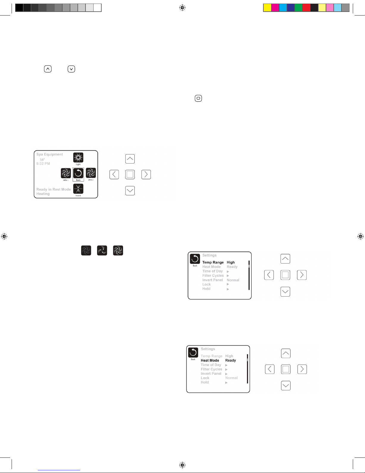
The Spa Screen
One Press Activation
e Spa Screen shows all available equipment to control, as well
as Invert, in one easy-to-use screen. Each button is xed on a
specic function and can be used as a very simple user interface
for the spa. e display shows icons that are related to the
equipment installed on a particular spa model, so this screen may
change depending on the conguration.
e pumps have more than one ON state, so the icon will change
to reect the state that the equipment is in. Below are some
examples of 2-speed Pump indicators:
NOTE: e icon for the pump that is associated with the
heater (Filtration Pump) will have a red glow in the center when
the heater is running.
Light Operation
By turning the light on and o, it will change the sequence of
colors from ashing, to fading, to solid color in the following
sequence:
1. Color wheel: Color changes quickly through available
solid colors.
2. Color fade: Colors fade through spectrum A colors.
3. Random Color Change: Random color changes occur in
quick succession.
4. Spectrum fade: Colors fade through spectrum B colors.
5. Solid Color: Red
6. Solid Color: Green
7. Solid Color: Blue
8. Solid Color: Yellow
9. Solid Color: Indigo
10. Solid Color: Orange
11. Solid Color: Violet
12. Solid Color: White
The Settings Screen
e Settings Screen is where all programming and other spa
behaviors are controlled. is screen has several features that can
be acted on directly. ese features include Temp Range, Heat
Mode, and Invert Panel. When one of these items is highlighted,
the Select Button is used to toggle between two settings. All
other menu items (with an arrow pointing to the right) will take
you to another level in the menu.
Press-and-Hold
If an Up or Down button is pressed and held when an item in a
Menu List is highlighted, the list can be scrolled quickly from top
to bottom. e scroll bar on the right side of the screen indicates
the relative position of the highlighted item in the list.
Dual Temperature Range
(High vs. Low)
Your spa comes equipped with two temperature range settings
with independent set temperatures. e specic range can be
selected on the Settings screen and is visible on the Main Screen
in the upper right corner of the display. High Range can be set
between 80°F (26.7°C) and 104°F (40°C). Low Range can be
set between 50°F (10°C) and 99°F (37.2°C). e most common
use for the low range is during vacations or extended periods of
inactivity. Freeze Protection is active in either range.
Heat Mode – Ready vs. Rest
When in “Ready” mode, the pump that circulates water through
the heater will turn on every 1/2 hour to measure water
temperature, heat if needed, and refresh the temperature display.
When in Ready mode your spa will continually maintain its set
temperature. REST mode is recommended for most economic
performance.
Ready-in-Rest Mode
READY/REST appears in the display if the spa is in Rest Mode
and the Jets 1 Button is pressed. It is assumed that the spa is
being used and will heat to set temperature. While Pump 1
High can be turned on and o, Pump 1 Low will run until
set temperature is reached, or 1 hour has passed. After 1
The Spa Screen
The pumps have more than one ON state, so the icon will change to refl ect the state that the equipment is in.
Below are some examples of 2-speed Pump indicators.
Jets HighJets LowJets Off
One-Press Activation
Ready in Rest Mode
Heating
Spa Equipment
Jets 1
Jets 2
Light
Back
The Spa Screen shows all available equipment to control, as well as Invert, in one easy-to-use screen. Each button is
fixed on a specific fuction and can be used as a very simple user interface for the spa The display shows icons that are
related to the equipment installed on a particular spa model, so this screen may change depending on the installation.
Invert
8:32 PM
104°F
2016 V&B Owners Manual.indd 16 3/3/2016 1:45:57 PM
Page 17

17
hour, the System will revert to Rest Mode. is mode can also
be reset by entering the Settings Menu and changing the Heat
Mode.
Time Settings
Setting the time is important for ltration settings and other
background settings to function as expected. “Set Time” will
appear on the display if no time-of-day is set in the memory.
From the main menu, navigate to the Settings line by using the
and keys. Press to enter the Settings Menu. On the
Settings Screen, select the Time of Day line using the and
keys. Press to enter the Time of Day menu. On the Time
of Day screen, simply navigate and right and left to select
the Hour, Minutes, AM/PM and 12/24 Hour segments. Use the
Up and Down Buttons to make changes.
When changes are made, the “Back” button will be replaced by a
“Save” button and a new icon for “Cancel” appears under the Save
icon. Press while the Save button is selected to con rm your
selection.
Light Timer
Your spa is equipped with a timer that, when engaged, will
turn the interior and exterior lights on and o . To set the light
timer, from the main menu, use the or buttons to select
“Settings,” press , to enter the Settings Menu. Press to
enter the menu list. Use the and buttons to select “Light
Cycle”. Press
to enter the menu. Press to enter the menu
list. Press
or to enable the Light Timer. Press to
select the hour, minute, and duration of the light cycle. When
changes are made, the “Back” button will be replaced by a “Save”
button and a new icon for “Cancel” appears under the Save
icon. Press while the Save button is selected to con rm your
selection.
Saving Settings
roughout your use of the settings screen, save your settings by
following these steps:
When changes are made, the icon to go “Back” changes to
“Save” and a new icon for “Cancel” appears under the Save icon.
Navigating to the left will highlight the Save icon, and navigating
down from there will allow the user to cancel the pending change.
Pressing the “Select” button will save or cancel the changes and
go back to the previous screen.
Adjusting Filtration
NOTE: Your spa’s factory default lter cycle start times are
8:00am and 6:00pm daily. When using the most economical “rest”
mode, it is recommended that you adjust the ltration cycles to
run just prior to the time of your usual spa use.
Filter Cycle 1
Using the same navigation and adjustment as Setting the Time,
Filter Cycles are set using a start time and a duration. Each
setting can be adjusted in 15-minute increments. e panel
calculates the end time and displays it automatically.
Filter Cycle 2
Simply navigate to the Filter Cycle 2 line by pressing the Right
Navigation button, and when “Yes” is highlighted, press Up or
Down to toggle Filter Cycle 2 on and o . When Filter Cycle 2
is ON, it can be adjusted in the same manner as Filter Cycle 1 by
navigating to the right. It is possible to overlap Filter Cycle 1 and
Filter Cycle 2, which will shorten overall ltration by the overlap
amount.
Purge Cycles
In order to maintain sanitary conditions, as well as protect against
freezing, secondary water devices will purge water from internal
spa components by running all pumps at the beginning of each
lter cycle. If Filter Cycle 1 is set for 24 hours, enabling Filter
Cycle 2 will initiate a purge when Filter Cycle 2 is scheduled to
begin.
Restricting Operation
e control can be restricted to prevent unwanted use or
temperature adjustments. Locking the Panel prevents the
controller from being used, but all automatic functions are still
active. Locking the Settings allows Jets and other features to be
used, but the Set Temperature and other programmed settings
cannot be adjusted.
Adjusting Filtration
Filter Cycle 1
Using the same navigation and adjustment as Setting the Time, Filter Cycles are set using a start time and a duration. Each
setting can be adjusted in 15-minute increments. The panel calculates the end time and displays it automatically.
Filter Cycles
Back
Filter Cycle 1
Starts at 12:00 AM
Runs 0 HR 0 Min
Ends at 12:00 AM
Filter Cycle 2 NO
Starts at 12:00 AM
Runs 0 HR 0 Min
Ends at 12:00 AM
Filter Cycles
Back
Filter Cycle 1
Starts at 6:15 AM
Runs 3 HR 0 Min
Ends at 9:15 AM
Filter Cycle 2 NO
Starts at 12:00 AM
Runs 0 HR 0 Min
Ends at 12:00 AM
Cancel
Save
2016 V&B Owners Manual.indd 17 3/3/2016 1:46:00 PM
Page 18

18
Unlocking
An Unlock Sequence using the navigation buttons can be used
from the Lock Screen. e Unlock Sequence is the same for both
Panel Lock and Settings Lock. You must enter and highlight
“Unlock” then enter and highlight panel “ON” before entering the
unlock sequence.
Additional Settings
Hold Mode
e “Hold” function prevents the jets from running to allow
JetPaks to be swapped out. By default, a hold lasts 60 minutes, or
until the Exit button is pressed.
Utilities
e Utilities Menu contains the following:
A/B Temps
When this is set to On, the temperature display will alternate to
display temperature from Sensor A and Sensor B in the heater.
Fault Log
e Fault Log is a record of the
last 24 faults that can be reviewed
by a service tech.
RCD Test
is screen allows the RCD
to be tested manually from the
panel and can be used to reset the
automatic test feature. If the RCD Test Feature is reset, the device
will trip within 7 days. (See RCD Test Section)
Preferences
e Preferences Menu allows the
user to change certain parameters
based on personal preference.
Temp Display
Change the temperature between
Fahrenheit and Celsius.
Time Display
Change the clock between 12 hr and 24 hr display.
Reminders
Turn the reminder messages (like “Clean Filter”) On or O .
Cleanup
Cleanup Cycle Duration is not always enabled, so it may not
appear. When it is available, set the length of time Pump 1 will
run after each use. 0-4 hours are available.
Color
Pressing the Select Button when Color is highlighted will cycle
through 5 background colors available in the control.
Language
Change the language displayed on the panel.
Information
e System Information Menu displays various settings and
identi cation information that might be used by a service
technician. As each item in the menu is highlighted, the detail
for that item is displayed at the bottom of the screen.
Stereo Controls (Optional)
For Premium Series Spas with optional stereo systems
If your spa is equipped with an “Elite” Audio system, refer to its
separate manual for operating instructions. If your spa has a Life
Audio system, the spa’s A900 control pad will control various
functions of Bluetooth connected devices.
From the main screen, select “A/V” using the up or down arrow
buttons to the right of the screen. Select “A/V” by pressing the
center square button.
On the A/V screen use the up, down, left, or right arrow buttons
to highlight desired function., then press center square button to
select.
e rst time you use your Bluetooth device with a Life Audio
system you must rst “pair” your device to the spa audio system.
Each device must be paired separately.
1. Turn on your Bluetooth device and place within 20 feet (6
meters) of your spa. e device must have “line of sight”
to the spa control panel / equipment door area. (NOTE:
Certain house construction materials and other obstructions
can impact Bluetooth connectivity. You may need to
experiment with where to place your BT device for best
results.)
2. From the main spa screen, select “A/V” using the up or down
arrow buttons to the right of the screen. Select “A/V” by
pressing the button.
Fault Log
Back
Entry 2
Message Code M026
1 Days Ago 2:21PM
Rest Mode
High Range
Set Temp 104°F
Sensors: A: 100 B: 96
Message:
Sensors are out of sync
Preferences
Back
Temp Display
Time Display
Reminders
Cleanup
Color
Language
°F
12 HR
On
0.5 HR
`
Blue
English
`
BT
BT
Track +
Track -
2016 V&B Owners Manual.indd 18 3/3/2016 1:46:03 PM
Page 19

19
After approximately 15-20 seconds, “PPGME60” will appear
in the Bluetooth device list on your electronic device. Select
“PPGME60” from your device’s list to connect and “pair” your
device to the Life Audio system. After a few seconds the pairing
will complete and audio from your device will start playing on
the spa audio system. Your Bluetooth devices need only be paired
the rst time you use a new device. After that your device will
connect automatically.
BT
BT
Track +
Track -
Return to
Main Screen
Power On or
OFF Life Audio
Play/ Pause Volume UP
Next Track
Switches
Audio Source
(“Line in” not used.
Uses only “Bluetooth”)
Volume DOWN Previous Track
Life Audio System Status
Powering Up- Connecting, may take 10-15 seconds
Powering Down- Turns Life Stereo o
BT Connected- Indicates your Bluetooth device is connected
Discoverable-System is searching for Bluetooth devices available
for pairing (see next page for pairing instructions)
2016 V&B Owners Manual.indd 19 3/3/2016 1:46:04 PM
Page 20

20
JETS 2
LIGHT
JETS 1
HEAT
JETS 2
JETS 1
LIGHT
MENU
SELECT
Preparation and Filling
Fill the spa to its correct operating level. (See SPA
MAINTENANCE section of this manual.) Be sure to open all
valves and jets in the plumbing system before lling to allow as
much air as possible to escape from the plumbing and the control
system during the lling process. After turning the power on at
the main power panel, the control panel display will go through
specic sequences. ese sequences are normal and display a
variety of information regarding the conguration of the hot tub
control. After a few seconds, the spa will go into priming mode
and will display “PR”.
Priming the Pumps
As soon as the priming mode menu appears on the panel, press
the
“Jets 1” button once to start Pump 1 in low-speed and
then again to switch to high-speed. Next, if your spa is equipped
with a second pump press the Jets 2 or “Aux” button twice, to
turn it on high. e pumps will now be running in high-speed to
facilitate priming.
IMPORTANT: A pump should not be allowed to run
without priming (water owing out of the jets) for more than 2
minutes. Under NO circumstances should a pump be allowed to
run without priming beyond the end of the 4-5 minute priming
mode. Doing so may cause damage to the pump and cause the
system to energize the heater and go into an overheat condition.
NOTE: Turning the power o and back on again will initiate a
new pump priming session. Sometimes momentarily turning the
pump o and on will help it to prime. Do not do this more than
5 times. If the pump(s) will not prime, shut o the power to the
spa and call for service.
Exiting Priming Mode
You can manually exit Priming Mode by pressing the or
button. Note that if you do not manually exit the priming mode
as described above, the priming mode will automatically end
after 4-5 minutes. Be sure that the pump(s) have been primed by
this time. Once the system has exited Priming Mode, the control
panel will momentarily display the set temperature. e system
requires approximately 1-2 minutes of water owing through the
heater to determine and display the correct water temperature.
Light Operation
By turning the light on and o, it will change the sequence of
colors from ashing, to fading, to solid color. Use the light button
COMFORT LINE SPAS
JETS 2
LIGHT
JETS 1
HEAT
JETS 2
JETS 1
LIGHT
MENU
SELECT
Jets 1
Press to toggle jets
LOW/HIGH/OFF
Jets 2
Press to toggle jets
LOW/HIGH/OFF (for
spas equipped with
dual pumps)
Lights Toggle
Press to toggle lights
ON/OFF
Down Button
Used to move through
menu selections
Up Button
Used to move through
menu selections
Menu/Select
Used to make
menu selections
2016 V&B Owners Manual.indd 20 3/3/2016 1:46:09 PM
Page 21

21
to choose a stationary spa light color or a colored changing series.
Each time the light is turned o and then on it will advance
according to the following sequence:
1. Color wheel: Color changes quickly through available
solid colors.
2. Color fade: Colors fade through spectrum A colors.
3. Random Color Change: Random color changes occur in
quick succession.
4. Spectrum fade: Colors fade through spectrum B colors.
5. Solid Color: Red
6. Solid Color: Green
7. Solid Color: Blue
8. Solid Color: Yellow
9. Solid Color: Indigo
10. Solid Color: Orange
11. Solid Color: Violet
12. Solid Color: White
Main Menus
Navigation
e R600 control pad is navigated by the use of three control
buttons.
“Menu Select,” “Up” and “Down.” If at any
time during the control sequences a key is not pressed for several
moments, the menu will revert to the display and you will need to
start the sequence from the beginning.
Hold (Standby)
Hold Mode
e “Hold” function prevents the jets from running to allow
JetPaks to be swapped out. By default, a hold lasts 60 minutes, or
until the menu is exited manually. To put spa in “HOLD,”
1. 1. Press the “Menu Select” button once. “HOLD” will
ash on the display.
2. 2. Press the up arrow to enter “HOLD” mode. “HOLD
MODE” will last for 60 minutes.
3. 3. Press or to exit HOLD mode manually.
Show and Set Time of Day
Setting the time is important for ltration settings and other
background settings to function as expected. To set the time:
1. 1. Firmly press and hold Menu Select several times until
“TIME” displays on the display.
2. 2. Press the or keys to select the hour. Once you have
selected the correct hour, press the key to move to the
minute selection.
3. 3. Press the and keys to select the minutes. Press
to conrm your selections and exit the Time selection menu.
Selecting 12, or 24 hour clock
Press several times until “PREF” displays on the display.
Press the or button to enter the Preferences Menu. “F/C”
will display on the display. Press the button until “24-12”
displays on the display. Press or to enter the Time
Selection Menu. Select your preferred time clock setting. Press
to return to the Preferences Menu.
Temperature and Temp
Range
Adjusting the Set Temperature
Pressing the and buttons (Temperature buttons) will
cause the temperature to ash. Pressing the
or button
again will adjust the set temperature. Holding the or
button will cause the temperature to change until the button is
released. When the desired temperature is reached, press to
conrm your setting. When the LCD stops ashing, the spa will
heat to the selected temperature.
Dual Temperature Range
(High vs. Low)
is system incorporates two temperature range settings with
independently set temperatures. To select a range:
1. 1. Press several times until “TEMP” is visible in the
display window. “RANGE” will ash in the bottom right
of the screen with an up or down arrow to indicate which
selection is currently active. e most common use for the
low range is during vacations or extended periods of non-use.
2. 2. Press the or buttons to switch between High
and Low. When a range is chosen, the spa will heat to the
set temperature associated with that range and hold. High
Range can be set between 80°F and 104°F. Low Range can
be set between 50°F and 99°F. Freeze Protection is active in
either range.
Heat Mode – Ready vs. Rest
When in “Ready” mode, the pump that circulates water through
the heater will turn on every 1/2 hour to measure water
temperature, heat if needed, and refresh the temperature display.
When in Ready mode your spa will continually maintain its set
temperature. REST mode is recommended for most economic
performance.
To Set Heat Mode (Ready or Rest)
Press several times, until “MODE” appears in the display
window. Press . e selected mode will ash at the bottom left
of the display screen. Press or to change the selected heat
mode. Press to conrm your selection.
Ready-in-Rest Mode
When the spa is in Rest mode and a “Jet” button is manually
pressed, the spa will enter Ready-in-Rest mode and heat up to
the selected temperature, allowing for use in periods outside
of scheduled lter cycles.
Preparation and Filling
Fill the spa to its correct operating level. Be sure to open all valves and jets in the plumbing system before fi lling to allow
as much air as possible to escape from the plumbing and the control system during the fi lling process.
After turning the power on at the main power panel, the top-side panel display will go through specifi c sequences. These
sequences are normal and display a variety of information regarding the confi guration of the hot tub control.
Priming Mode
This mode will last for 4-5 minutes or you can manually exit the priming mode after the pump(s) have primed.
Fill it up!
2016 V&B Owners Manual.indd 21 3/3/2016 1:46:10 PM
Page 22

22
Flip Display
To ip the display, press until the display reads “FLIP.” Press
the or key. is will invert the display.
Restricting Operation
e control panel can be restricted to prevent unwanted use
or temperature adjustments. is lock feature prevents most
functions on the controller from being used, while all automatic
functions remain active. “TEMP” locks the temperature selection,
preventing unwanted temperature adjustments . “PNL” in
contrast, locks all changes from the panel. Features will function
as selected.
To Lock Temperature or Panel
To lock the settings, press several times until “LOCK” is
displayed. Press
or to select the lock menu. “TEMP” will
display in the display window. Press Press , “OFF” will
display in the window. Press , or to select “ON.” Press
to conrm your selection. is will lock the temperature
settings. Follow the same process, and select “OFF” to turn o
the lock function.
To lock the panel, press several times until “LOCK” is
displayed. Press to select the lock menu. “TEMP” will
display. Next press and “PANL” will display in the window.
Press , “OFF” will ash in the display window. Press or
to change the setting to “ON.” Press to conrm the panel
lock.
To Unlock Temperature or Panel
Press and hold and simultaneously twice for about a
second each time. “UNLK” will display in the window and the
temperature or panel controls will return to normal.
NOTE: If both “PANL” and “TEMP” are locked, the unlock
procedure must be performed twice.
Filtration Cycles
Your Comfort Series Spa comes factory programmed to run two
cycles in each 24 hour period.
Filter Cycle 1: Begins at 6:00pm (18:00) and runs for 2 hours
for single pump spas and 3 hours for dual pump spas.
Filter Cycle 2: Begins at 8:00am (8:00) and runs for 1 hour
for both single pump and dual pump spas.
ese factory set ltration cycles should be adequate for light to
normal spa use (spas used once to twice per week). For cases of
more frequent, to heavy spa usage, you may need to increase the
lter cycle durations to maintain water clarity.
Changing Filter Cycles:
To change lter 1 cycle:
1. Press “MENU SELECT” button several times until
“FLTR1” appears on the display.
2. Press
button, “BEGN” will appear. is indicates
Filter Cycle 1’s “begin time.”
3. Press button again. e hour digit will ash. Press
button or button to adjust hour. (NOTE: “A” for am
or “P” for pm will be displayed in the bottom right corner of
the display window).
4. Press button. Minutes will be ash. Press button
or button to adjust duration of the pump cycle in 15
minute increments.
5. Press button to save your selection. “RUN HRS” will
appear. Press button to display Filter 1(“F1”) end time.
Push button to go to Filter 2.
To change lter 2 cycle:
1. Press button several times until “FLTR2” appears.
2. Press button to toggle between “ON” and “OFF”
(NOTE: Filter 2 cycle can be turned o. However, this is
not recommended and can lead to poor water clarity).
3. Press button. “BEGN” will appear. Press button,
hour will begin to ash. Press button or button to
adjust the starting time for Filter 2 ltration. (NOTE: “A”
for am or “P” for pm will be displayed in the bottom right
corner of the display window).
4. Press button. Minutes will begin to ash. Press
button or button to adjust duration of the pump cycle in
15 minute increments.
5. Press button to save your selection. “RUN HRS” will
appear. Press button to display Filter 2 (F2) end time.
Press button.
“LITE TIMR” is not functional in Comfort Series Spas.
To Change Preferences
Changing temp display between
Fahrenheit (F) and Celcius (C)
Press several times until “PREF” appears in the display
window. Press , “F/C” will appear. Press to conrm your
changes.
Changing 12 or 24 hour clock
Press several times until “PREF” appears in the display
window. Press , “F/C” will appear. Press , “24-12” will
display in window. Press , the current selection will ash.
Press until the desired setting is selected. Press to
conrm your selection.
Turning reminders OFF or ON
Press several times until “PREF” appears in the display
window. Press , “F/C” will appear. Press several times until
“RE-MIN-DERS” begins to scroll through the display. Press
, the current selection will begin to ash in the window. Press
to change to your desired selection. Press to conrm your
selection.
Set Cleanup Cycle
2016 V&B Owners Manual.indd 22 3/3/2016 1:46:12 PM
Page 23

23
e cleanup cycle, is a maintenance cycle designed provide
additional circulation and ltration between regular lter cycles.
It runs 30 minutes after each spa use.
To adjust the duration of the
cleanup cycle:
Press several times until “PREF” appears in the display
window. Press , “F/C” will appear. Press several times
until “CLN—UP” displays in the window. Press , the current
duration of the cycle will begin to ash in the window. Choose
a duration time from 0.0 hours to 4.0 hours, by pressing or
until the desired time displays in the window. Press to
conrm your selection.
NOTE: e Preferences Menu may list “DOL-PHIN” as an
option. However this function is not used in Comfort Series
spas.
Stereo Controls (Optional)
If your spa is equipped with an “Elite” Audio system, refer to its
separate manual for operating instructions. If your spa has a “Life”
Audio system, the spa’s R600 control pad turn the audio system’s
Bluetooth function On and O.
e rst time you use your Bluetooth device with a Life Audio
system you must rst “pair” your device to the spa audio system.
Each device must be paired separately.
Turn on your Bluetooth device and place within 20 feet (6
meters) of your spa. e device must have “line of sight” to the
spa control panel / equipment door area.
NOTE: Certain house construction materials and other
obstructions can impair Bluetooth connectivity. You may need to
experiment with where to place your BT device for best results.
To turn on Bluetooth
Press several times until “BT” appears in the display window.
Press to activate Bluetooth. After approximately 15-20
seconds, “PPGME60” will appear in the Bluetooth list of your
electronic device. Select “PPGME60” from the list to connect and
“pair” your device to the Life Audio system. After a few seconds
the pairing will complete and audio from your device will start
playing on the spa audio system. Your Bluetooth devices need
only be paired the rst time you use a new device. After that your
device will connect automatically.
2016 V&B Owners Manual.indd 23 3/3/2016 1:46:21 PM
Page 24

24
Light
Jets 2
Jets 1
SERIES
Temp
Heat
Your spa is pre-programmed with default lter cycles and
temperature settings. e following control panel instructions will
detail the procedures to alter such default settings.
Select and Basic Control
Systems
General
Some functions require pressing multiple buttons on the control
pad in a certain sequence. is is indicated by a “+” sign in the
instruction (for example: press temp + light to enter mode
programming). Do not press the buttons at the same time or too
quickly, or the desired result may not occur.
Initial Startup
Before turning on the power to the spa, make sure the spa is
properly lled with water. When your spa is rst powered up,
it will automatically go into “Priming mode”, Press the “Jets 1”
button once to start Pump 1 in low-speed and then again to
switch to high-speed. Next, if your spa is equipped with a second
pump press the Jets 2 or “Aux” button, to turn it on. e pumps
will now be running in high-speed to facilitate priming. Once
the lter pump has been running for at least 2 minutes, the actual
water temperature will be displayed.
IMPORTANT: A pump should not be allowed to run
without priming (water owing out of the jets) for more than 2
minutes. Under NO circumstances should a pump be allowed to
run without priming beyond the end of the 4-5 minute priming
mode. Doing so may cause damage to the pump and cause the
system to energize the heater and go into an overheat condition.
NOTE: Any time the spa lter pump has not been running for
a period of time, the LCD display will usually read “--”, which
means the temperature is unknown because the temperature
sensors in the heating unit require the water to be circulating
past them for a couple minutes before calculating a true water
temperature reading.
Setting the Temperature: 80°F-104°F
(26°C-40°C)
Unless changed by the user, the default set temperature from the
factory is 100°F (38°C). To change the spa water temperature,
press “Temp” once to display the current set temperature it will
ash, then press “Temp” additional times to increase (or decrease)
the set temperature. To change the temperature adjustment
direction (from increase to decrease), pause 5 seconds between
pressing “Temp,” then push “Temp” again to desired temperature.
After 3 seconds, the LCD will again display the current spa water
temperature.
Spa Operating Modes
A multi-button sequence is used to switch between Standard,
Economy, and Sleep modes. Press temp + light buttons repeatedly
to cycle through modes.
Standard Mode (St): When in Standard mode, the
pump that circulates water through the heater (heat pump) will
turn on every 1/2 hour to measure water temperature, heat if
needed, and refresh the temperature display. To place your spa in
Standard mode, press temp + light repeatedly until “St” displays
on the screen.
Economy Mode (Ec): When in economy mode
the spa only circulates and heats water during designated lter
cycles. As a result, in the time period between ltration cycles the
control may not display the correct water temperature unless the
heater pump is on and has been running for up to two minutes.
When in Economy mode your spa will heat to its set temperature
twice per day during programmed lter cycles. To place your
spa in Economy mode, press temp + light repeatedly until “Ec”
displays on the screen.
NOTE: Spa owners using “Economy Mode” which heats only
during ltration cycles, may choose to change to “Standard” mode
while using the spa. is will enable the spa to heat and better
maintain temperature during spa use. Spa can be changed back to
“Economy Mode” when exiting the spa.
Sleep Mode: heats the spa to within 20°F/10°C of the
set temperature only during lter cycles. is mode is most
commonly used during long periods of non-use. To place your
spa in Sleep mode, press temp + light repeatedly until “SL”
displays on the screen.
Since it takes several hours to bring the spa water back up
to set temperature for comfortable use, Sleep Mode is only
recommended if the spa will not be used for 2-3 weeks or more.
Jets 1
Press “Jets 1” to turn pump 1 on and o. If left running, the pump
will automatically turn o after 30 minutes.
Jets 2 (optional)
If your spa is equipped with a two jet pump system, press “Jets 2”
to turn pump 2 on or o. If left running, the pump will turn o
automatically after 30 minutes.
LED Lights
Press l “Light” button to turn the LED lights on and o. To
toggle between all the LED color options, press the light
X SERIES SPA CONTROL SYSTEM
2016 V&B Owners Manual.indd 24 3/3/2016 1:46:21 PM
Page 25

25
button on, then o, then wait about 1 second and turn on again.
A dierent color option will appear*. e LED light will turn o
automatically after 1 hour.
Color options:
Each time the light is turned on and o it will advance according
to the following sequence:
1. Color wheel: Color changes quickly through available
solid colors.
2. Color fade: Colors fade through spectrum A colors.
3. Random Color Change: Random color changes occur in
quick succession.
4. Spectrum fade: Colors fade through spectrum B colors.
5. Solid Color: Red
6. Solid Color: Green
7. Solid Color: Blue
8. Solid Color: Yellow
9. Solid Color: Indigo
10. Solid Color: Orange
11. Solid Color: Violet
12. Solid Color: White
Preset Filter Cycles
ere are two lter cycles per day. e rst lter cycle begins 6
minutes after the spa is powered up. e second lter cycle begins
12 hours after the start of the rst cycle.
e ltration pump will run during ltration cycles. If you spa
is equipped with more than one pump, the additional pumps
will run for the rst few minutes of each lter cycle to purge
the plumbing. e factory lter cycle duration is 2 hours. Filter
duration can be set to 2,4, 6, or 8 hours. Continuous ltration can
also be selected (indicated by “FC”).
To program lter duration, press “Temp” + “Jets 1.” Press “Temp”
to adjust*. Press “Jets 1” to exit programming. *F2= 2 hour
ltration, twice per day, F4= 4 hour ltration, twice per day, Etc.
NOTE: Allowing the lter pump to operate for extended
periods of time with the cover on the spa will result in a rise of
the spa water temperature. During warmer months of the year,
it is advisable to set the duration of the ltration cycle to the
minimum level needed to keep the water clean.
Freeze Protection
If the temperature drops to 44°F (7°C) within the heater, the
pump(s) automatically activates to provide freeze protection. e
pump will stay on 4 minutes after the sensor has detected the
temperature has reached 45°F (7°C) or higher.
Ozone Purier
e optional ozone purier runs during lter cycles and whenever
the spa is heating.
2016 V&B Owners Manual.indd 25 3/3/2016 1:46:25 PM
Page 26

26
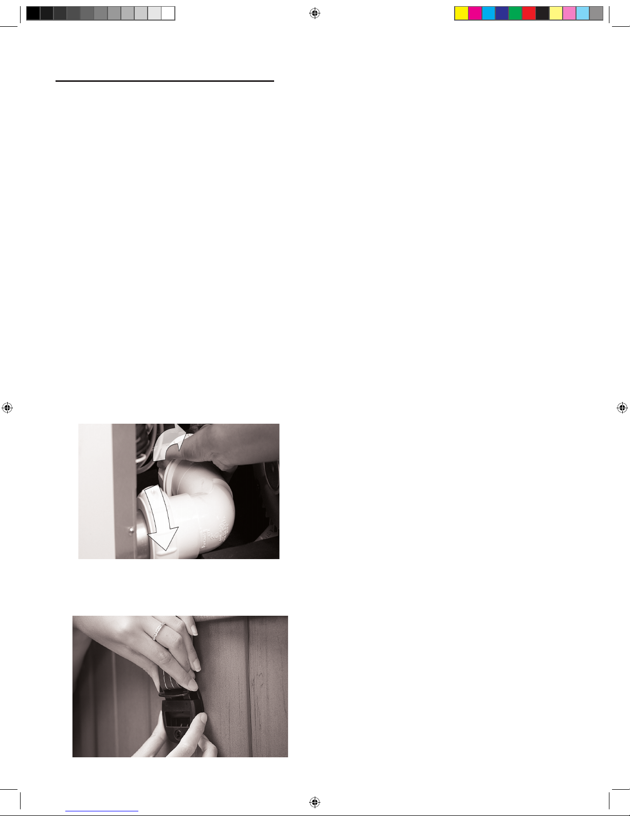
Interchanging JetPaksPremium Series,Comfort
Series, and Design Series
Step 1: Put the spa in “Hold”, this will prevent the pump(s)
from activating (see Control Systems).
Step 2: Remove the head rest and Snap-Cap by lifting upwards.
CAUTION! WHILE PERFORMING STEPS 3&4 YOU
MUST USE THE BLACK MANIFOLD AREA AS THE
POINT OF CONTACT AS SHOWN IN THE PICTURE.
PRESSURE APPLIED TO THE FRONT FACE (ACRYLIC
PLATE) MAY CAUSE DAMAGE TO THE JETPAK
VOIDING THE WARRANTY
Step 3: While applying pressure downward on the manifold
push the manifold away from you toward the inside of the spa
to release the manifold from the wall clip assembly, then lift the
plate straight up to remove.
Step 4: Exchange JetPak
Step 5: Lower the manifold of the new JetPak carefully as to
align the lower valve assembly and gasket into the bulkhead
tting. Apply pressure downward as you pull the JetPak manifold
toward you to until the manifold is secured in the wall clip
assembly .
Step 6: Reattach the Snap-Cap and head rest.
Jets
Jet Types
A unique combination of the nest jets available are chosen
to optimally balance each JetPak with ideal performance and
massage intensity. You can achieve virtually limitless therapy
options by adjusting many of the jets for a custom experience.
Adjustable Jets Premium, Comfort and
Design Series
To adjust the water ow to Premium, Comfort and Design Series
JetPaks, turn the valve located in the lower portion of each JetPak.
• To increase jet water pressure, turn the valve handle counter
clockwise
• To decrease jet water pressure, turn the valve handle
clockwise To adjust the water ow to A, R & S Series jets in
the shell, turn the inner jet face.
• To increase jet water pressure, turn the jet face clockwise
• To decrease jet water pressure, turn the jet face counter
clockwise
JETPAKS & JETS
2016 V&B Owners Manual.indd 26 3/3/2016 1:46:36 PM
Page 27

27
Adjustable Jets X Series Spas
To adjust the water ow on adjustable jets, simply turn the outer
ring.
• To increase jet water pressure, turn the outer ring clockwise
• To decrease jet water pressure, turn the outer ring counter
clockwise
NOTE: Turning o jets will increase pressure to other jets on
same pump. To avoid unnecessary system pressure never shut o
all jets at the same time.
NOTE: To allow for proper circulation, the valve located in A,
R & S Series JetPaks is designed to adjust jet pressure, but will
not completely stop jet ow.
2016 V&B Owners Manual.indd 27 3/3/2016 1:46:36 PM
Page 28

28
Chemicals
Properly maintaining your spa water is very important to
ensure enjoyment in using your spa and to maximize spa shell
and equipment life. Maintaining your spa water chemistry will
require regular attention to prevent poor water quality, potential
unhealthy conditions, and possible damage to your spa.
For specic help in maintaining water quality, consult your
Authorized Villeroy & Boch Spa dealer who can recommend the
correct products and procedures for sanitizing and maintaining
your spa.
CAUTION:
• Always follow chemical manufacturers’ instructions and
never mix chemicals.
• Use an accurate test kit to perform all chemical tests.
• Add chemicals directly to the spa, evenly spreading the
chemicals over the surface of the water with the jets
operating, or use an appropriate feeding or metering device
and check chemical levels often.
• Run the lter pump on high speed for at least 15 minutes
after applying any chemicals.
• Names of spa chemicals will vary from one manufacturer
to another. Please contact your authorized Villeroy & Boch
dealer if you have any questions.
Starting the Spa with New Water
IMPORTANT: Never ll the spa with soft water unless an
appropriate mineral supplement is immediately added. If your
water is extremely hard, it is preferable to either dilute the water’s
hardness by blending the water with water from a water softener,
or by the addition of a special water softening chemical. For more
information, contact your authorized Villeroy & Boch Spa dealer.
Step 1: Add the prescribed dose of Stain and Scale Inhibitor
while lling the spa. is will provide the initial protection
against staining and scaling. Once the spa is lled, add the
prescribed dose of Water Clarier. is will clear the water of any
micro-particulates that may be in the new water.
Step 2: If possible, have your authorized Villeroy & Boch dealer
test the Calcium Hardness (CH) of your spa. Adjust as per your
dealer’s recommendations.
Step 3: Test and adjust the Total Alkalinity (TA). e TA
should measure 125 to 150 parts per million (PPM).
Step 4: Test and adjust the pH. e pH should measure 7.4 to
7.6.
Step 5: If you use water clarier. After the spa water has
circulated for one hour, add ½ teaspoons of Granular Chlorine or
1 teaspoon of Granular Bromine per each 200 gallons (909.2l) of
spa water.
After several hours, check sanitizer level and adjust, if necessary,
to the following levels: Chlorine Level:
5.0 PPM (parts per million) Bromine Level: 6.0 PPM (parts per
million)
Step 6: Startup water chemistry is now complete. However, it
may take additional time for the lter to completely clear the
water.
Regular Spa Water Care
Sanitizer and pH Levels
It is important to test and adjust the sanitizer and pH level of
your spa on a frequent basis. If the spa is used 0-3 times weekly,
we recommend that you test the water a minimum of 2-3 times a
week. For each additional use, test the water one additional time.
Test kits and supplies are available from your authorized Villeroy
& Boch dealer.
pH Control: Proper pH balance is extremely important in
controlling bacteria, providing water that is comfortable to the
user, and preventing damage to the spa and equipment. e pH
scale ranges from 0-14. Levels of pH less than 7.0 are acidic while
pH levels greater than 7.0 are basic. e proper pH range for a
spa is 7.4-7.6.
High pH levels (greater than 7.6): Can cause scale build-
up on the spa and its equipment, cloudy water, a prematurely
dirty lter, and less eective chlorine sanitation. To correct high
pH levels, add a pH decreaser.
NOTE: Never use Muriatic or Hydrochloric acid to adjust pH
as it can damage the spa shell and surroundings.
Low pH levels (less than 7.4): Can cause discomfort to
the spa users and corrosion to the spa equipment. To increase pH
levels, add a pH increaser.
Always test, and adjust the pH level before you test
and adjust the sanitizer level.
Sanitation: Spa water sanitizers kill bacteria and keep the
water clean. Eective and safe sanitizers recommended by
Villeroy & Boch are Granular Chlorine (Dichlor) or Granular
Bromine. Chlorine and Bromine are the only two spa sanitizers
approved for use in spas by the EPA.
WARNING: Trichlor Chlorine tablets should never be used
in a portable spa. Dissolve rate, potency and the extreme low
pH of this chemical can cause severe damage to the spa surface
and components. Use of Trichlor Chlorine tablets will void the
Villeroy & Boch Warranty.
Bromine and Dichlor tablets are also not recommended as an
acceptable sanitizer in Villeroy & Boch unless an appropriate
feeding or metering device is used and the water is frequently
tested and monitored as excessive Bromine or Chlorine in the spa
can cause surface damage and component failure.
With each sanitizer test, use either granular Chlorine or
Bromine to maintain the following levels:
• Chlorine Level: 3.0 to 5.0 PPM (parts per million)
WATER CARE & CHEMISTRY
2016 V&B Owners Manual.indd 28 3/3/2016 1:46:36 PM
Page 29

29
•
Bromine Level: 3.0 to 6.0 PPM (parts per million)
Super Sanitation or Spa Shock
Normal sanitation does not eliminate non-lterable wastes,
such as perspiration, oils, hair sprays, etc., which will build up
in the water. ese substances make the water unattractive in
appearance, odor, and can interfere with sanitizer eectiveness.
Super sanitation is achieved by “shocking” the spa water with a
non-Chlorine shock (Potassium Peroxymonosulfate), granular
Chlorine (Dichlor), or granular Bromine (Bromine concentrate).
Super Sanitize the water once a week by adding one
of the following:
•
Granular Chlorine 2 teaspoons (10ml) of per 200 gallons
(909.2l) of water
• Granular Bromine 4 teaspoons (20ml) of per 200 gallons
(909.2l) of water
• Non-Chlorine Shock 5 teaspoons (25ml) of per 200 gallons
(909.2l) of water
NOTE: Super Sanitation may be required more than once
per week for heavy usage. With ozone, it may not be necessary
to shock the water on a weekly basis, contact your authorized
Villeroy & Boch dealer for more information.
Total Alkalinity (TA): Total alkalinity (TA) is the
quantitative measure ment of alkaline components (carbonates
and bicarbonates) present in water to act as a buer against rapid
pH changes. Proper total alkalinity levels are important to ensure
optimal chemical balance in spas. Low TA can cause pH to be
unstable. To correct low TA, add a Total Alkalinity Increaser.
High TA can cause the water to be scale forming, cloudy and
corrosive to the spa and its components, as well as other pH
related problems. If the spa water has high TA, contact your
authorized Villeroy & Boch dealer.
Calcium Hardness (CH): Calcium Hardness (CH) is the
measure of dissolved calcium in the water. Low CH (soft water)
can stain the spa surface as well as cause corrosion to the spa
and its equipment. To correct low CH, add a Calcium Hardness
Increaser. High CH (hard water) can cause cloudy water as well
as rough scale build-up on the spa surface and equipment. If the
spa water has high CH, contact your authorized Villeroy & Boch
dealer.
Stain and Scale Control: Stain and scale problems are
common in hot water environments. To help prevent and control
staining and scaling, use a Stain and Scale Inhibitor per the
manufacturer’s instructions. Add Stain and Scale Inhibitor 3-4
days after Super Sanitation.
Foam Control: Spa water that is polluted with body oils,
lotions and soap residue combined with high water temperatures
can cause excessive foaming on the water’s surface. For a
temporary x add a Foam Remover as per the manufacturer’s
instructions. e best way to control foam is to super chlorinate
the water; this will destroy the soap agents that normal levels of
sanitizer will not. Add 2 tablespoons (20 ml) per 100 gallons (
454.6 l).
Cloudy Water Prevention and Control: ere are two
basic reasons that spa water becomes cloudy. First, non-lterable
liquid waste (e.g. perspiration) has contaminated the water. To
remove these substances, Super Sanitize the water. Second, nonlterable micro-particulate waste (e.g. dust) has contaminated the
water. To remove these substances use a Water Clarier as per the
manufacturer’s instructions.
Water Chemistry
Troubleshooting
Prior to each spa use, check the water. If the water appears cloudy,
o color, has signicant surface foam, or smells of excessive
chlorine/bromine, the water needs to be treated or drained. Using
the spa in these conditions could result in a skin rash or other
irritations.
For assistance in handling spa water chemistry, contact your
authorized Villeroy & Boch dealer or another service center
capable of performing a computerized water analysis.
2016 V&B Owners Manual.indd 29 3/3/2016 1:46:36 PM
Page 30

30
WARNING:
An empty spa (spa without water in it) must not
be left exposed to sunlight as shell damage may occur. Once the
spa is unwrapped, ll spa with water immediately or shade the spa
with cover or wrapping to prevent direct exposure to sunlight.
Changing Spa Water
As you use your spa, soap and detergent residues from your skin
and bathing suits, along with other substances from maintaining
the spa’s water chemistry will accumulate in the spa water and
make maintaining the water more di cult. Rinsing your bathing
suits and showering without soap prior to entering your spa will
increase the life of your spa water. Depending upon usage, the
spa water will need to be changed every 1-4 months or when
the water chemical levels become di cult to manage. When
changing spa water, remove all JetPaks®. Clean the shell and
JetPod™ areas with a spa surface cleaner. See Spa Shell Care.
Clean the other areas of the spa, including JetPaks, with a spa
surface cleaner as necessary.
IMPORTANT: Drain your spa to an area that can handle a
large quantity of water. If draining water onto vegetation, make
sure that the sanitizer level (Chlorine or Bromine) of the water is
less than 0.5 PPM.
WARNING: Avoid drainage that can lead into basement
window wells or any other area where damage could occur.
To Drain Your Spa :
Step 1: Turn-o main electrical breaker to spa.
Step 2: Locate drain below equipment compartment door.
Step 3: Pull the drain out with a slight clockwise turn. Use
pliers if needed.
NOTE: Drain is fully extended at approximately 2 inches (5
centimeters).
Step 4: Remove drain cap.
NOTE: e drain spout will not drain when fully extended.
Step 5: Attach a standard garden hose. Push the drain spout in
halfway to actuate the drain.
NOTE: e Spa will drain about 5 gallons (20 liters) per
minute. Ensure that the drainage is in an area safely away from
window wells or basement entries.
Step 6: Once the spa is fully drained, pull the drain spout out all
the way, remove hose, replace the drain cap and push drain in all
the way.
To Re ll Your Spa:
WARNING: When re lling the spa, always Super Sanitize
the new water by adhering to the instructions in the Water
Chemistry section.
Step 1: To avoid air pockets in the pump(s) remove the spa
lter(s) and, re ll the spa with water by placing the hose into
the lter compartment. Fill to the water level indication on the
faceplate of the lter assembly.
Step 2: Restore electrical power supply.
Step 3: Press any button to reset the control system.
Step 4: Following instructions for your spa controller type.
Filter Maintenance
It is recommended that pleated lter cartridge(s) be cleaned
every 3-6 weeks or as needed. Spas equipped with the optional
circulation pump system may require increased cleaning intervals
based on use and local water conditions.
Replace the lter cartridge(s)
After multiple cleanings, worn lter cartridges will need to be
replaced. To maintain warranty protection, use only genuine
Villeroy & Boch Filter Cartridge replacements. To clean or
replace your lter cartridge(s), complete the following:
CAUTION: Never operate spa with the lter(s) removed.
Step 1: Place the spa in hold mode.
Step 2: Remove Filter SnapCap™ and lter plate.
(Premium Series, Comfort Series, or Design Series), or turn
SPA MAINTENANCE
2016 V&B Owners Manual.indd 30 3/3/2016 1:46:37 PM
Page 31

31
the main power o to the spa (X Series).
Step 3: Remove cartridge(s) by turning counter clockwise.
Step 4: Using a garden hose with a nozzle or other high-
pressure device, clean cartridge(s). Work top to bottom on each
pleat.
• To remove collected lotions or body oils, soak cartridge(s) in
warm water with a Filter Cleaner or detergent.
• To remove calcium deposits, soak cartridge(s) in a plastic
container using a 1:10 ratio of Muriatic acid to water
solution. Calcium deposits indicate a high spa pH, which
should be corrected.
NOTE: Filter(s) must be cleaned with a lter cleaner/
degreaser before at tempting to remove calcium and mineral
deposits with any acidic based product
Step 5: Reinstall cartridges, lter plate, and Filter SnapCap.
Step 6: Press any button to return the control system to normal
operation (Premium Series, Comfort Series or Design Series) or
restore the main power to the spa (X Series).
IMPORTANT: Using a brush to clean a lter cartridge could
cause damage to the lter media.
LED Light Replacement
Contact your authorized Villeroy & Boch Dealer for repair.
Spa Shell Care
e spa cover is an essential part of the spa system. It will both
protect the spa and to provide the highest possible eciency. To
ensure you have the best experience possible, ensure the cover is
in place except during spa use. e best protection for your comes
when the cover is on the spa with the skirt covering the entire
shell.
General Cleaning
For normal cleaning, use a mild dishwashing soap, window
cleaner, or other products recommended by your local authorized
Villeroy & Boch Dealer. For stubborn stains, use a mild acrylic
cleaner or a mild detergent. To apply these cleaners, use a soft,
damp cloth or sponge. Rinse well and dry with a clean cloth. To
clean hard water stains, remove light scratches and protect your
spa shell, contact your authorized Villeroy & Boch Dealer.
Cleaning the Scum Line
With normal use of the spa, oils, lotions, and hair products will
build up on the surface of the water. is will leave a scum line
around the perimeter. is can be easily removed using a spa
surface cleaner or its equivalent. Avoid using cleaning agents that
leave soap residue in the water.
WARNING: Never allow your spa surface to be exposed to
alcohol, acetone (nail polish remover), nail polish, dry cleaning
solution, lacquer thinners, gasoline, pine oil, abrasive cleaners,
or any other household chemicals other than those listed. ese
chemicals void the warranty.
Special Care For Comfort Series
Injection Molded JetPaks
High levels of sanitizer and normal use over time can have a
bleaching eect on the injection molded (dark gray) Jetpaks.
ese can be cleaned / bued to look like new again with the
aid of automotive polishing compound found at any automotive
retailer. Simply use a soft towel to rub this compound onto the
plastic. en bu with a dry towel.
JetPak™ Plumbing Care
For optimum spa care, each time the spa water is changed,
remove all JetPaks. Clean the back manifold area on with a spa
surface cleaner and a long, soft bristle brush. For cleaning the
JetPak acrylic surface, refer to Spa Shell Care.
Spa Cabinet Care
e EternaWood™ cabinet components are made to provide
many years of maintenance-free service. For normal cleaning,
use a mild dishwashing soap. For stubborn stains, contact your
authorized Villeroy & Boch Dealer.
Spa Cover Care
Your spa cover is warranted by its manufacturer. Although basic
instructions are provided below, it is important that you refer to
the information that came with the cover. e manufacturer
provides detailed information on caring for your spa cover
and what to do to protect its warranty.
2016 V&B Owners Manual.indd 31 3/3/2016 1:46:42 PM
Page 32

32
WARNING:
A non-secured, improperly secured, or damaged
cover may pose a safety threat to children and may also cause
damage or injury if blown o by wind. Always remove entire
cover before using the spa.
IMPORTANT: Do not stand, sit, or place any item on
the cover that could damage it. Gently remove any snow
accumulations over 2 inches (5cm). Always secure the cover with
all of the cover locks when not in use, whether the spa is empty or
full of water.
Cleaning the Spa Cover
At least monthly, clean the spa cover.
Step 1:
Remove the cover and lay it down on a at, clean surface
near a garden hose.
Step 2: Rinse the cover to remove any loose debris.
Step 3: Clean the top (vinyl) of the cover with a mild solution
of dishwashing soap, or other cleaner recommended by your
local authorized Villeroy & Boch Dealer. Apply cleaner with a
soft bristle brush. Using a gentle circular motion, scrub the cover,
being careful to not let any of the cover dry before rinsing with
water.
Step 4: Rinse the cover thoroughly and dry with a clean cloth.
Step 5: Use a spa cover protectant (never a petroleum-based
product) to condition the cover per your Villeroy & Boch dealer’s
instructions.
Step 6: Wipe and rinse any dirt from the bottom of the cover.
Step 7: Replace the cover and secure the locks.
NOTE: To remove tree sap, use lighter uid (the type used in
cigarette lighters). Use sparingly. Immediately apply a spa cover
protectant to the area.
Miscellaneous Care
Cleaning and Protecting the Pillows
Regularly clean all pillows with mild soap, water, and a clean
cloth. Monthly, treat pillows using a non-petroleum-based
conditioning product as recommended by your Villeroy & Boch
dealer. is will maintain water resistance and luster of the
product.
IMPORTANT: Remove the pillows when shocking the spa
or when sanitizer levels are high. Leave cover open for at least 30
minutes after shocking to ensure pillows are not aected.
NOTE: Pillow discoloration is accelerated by high sanitizer use
and is not covered by the Villeroy & Boch Warranty.
Vacuum the Spa
Debris from wind, trees, and users will occasionally accumulate
on the bottom of the spa. e ltration system will remove the
smaller debris. Large or heavy debris can be removed with a hand
held spa vacuum available at your Villeroy & Boch dealer.
Low-Use or No-Use Periods
During certain times of the year, you may not use the spa on a
frequent basis. For these low-use or no-use periods, consider the
following:
No Use for Two to Six Weeks
If the spa will not be used for at least two weeks, lower the
temperature to the lowest setting of 80 F (26°C) or place in low
range heat mode. Lowering the temperature will cut the cost
of operation, however; you will need to adjust the temperature
setting approximately 4 hours before use in order to heat the spa
to 100 F (38°C).
IMPORTANT: During all lowand no-use periods, be sure
to maintain the spa water as per the instructions in the Water
Chemistry section.
IMPORTANT: For all no-use periods, and on a weekly
basis, be sure to have someone visually check that the spa is
functioning correctly and to also maintain the spa water as per
the instructions under the Water Chemistry section. Not doing
so may lead to corrosion, staining, and/or scaling to the spa and
its equipment. During periods of freezing temperatures, a spa
that has malfunctioned may be subject to damaged plumbing
or equipment as a result of ice buildup within the spa. If the
spa cannot be checked and maintained on a weekly basis, then
consider winterizing the spa.
No use for over six weeks
When you are not planning to use the spa for six or more weeks,
or when someone is not able to maintain the spa on a weekly
basis, you should winterize the spa. To winterize, follow these
steps:
Winterization
WARNING: Prior to winterizing your spa, it will be necessary to
Super Sanitize the spa water as per the instructions in the Water
Chemistry section. is procedure will help prevent the growth
of bacteria, algae and fungi in any areas of plumbing that may
not be fully free of water after you drain your spa for its period of
winterization.
Step 1: Drain the water.
Step 2: If your spa is equipped with JetPaks, open all lower
valves to allow the water to drain form each pak as you drain the
spa. Once the water is completely out of the spa then close each
valve before starting proceeding to step 3.
Step 3: Use a wet shop vacuum to vacuum the plumbing lines by
placing the vacuum nozzle over each of the lower jet faces in the
spa. Lower jets are any at or below the bench seat area
Step 4: Remove the drain plug from the pump(s) and loosen all
PVC pipe unions in the equipment compartment. Do not replace
the plugs or tighten the unions until the spa is de-winterized.
Step 5: Clean the spa shell and JetPaks (if equiped).
2016 V&B Owners Manual.indd 32 3/3/2016 1:46:42 PM
Page 33

33
Step 6:
Remove lter cartridge(s), clean, and reinstall.
Step 7: Secure the cover to the spa utilizing the tie downs and
locking system. In areas where heavy snow is anticipated, place a
large piece of plywood (or its equivalent) on top of the spa cover
to assist in supporting the cover with the added weight of the
snow. Remove snow o the cover following each snow storm.
WARNING: To avoid water from becoming trapped between
the oor suction tting and the lter pipe . Use a wet/dry vacuum
to remove the remaining water out of pipe by placing the vacuum
end over the lter hole. In a two-pump spa, rst plug o one
lter using a tennis ball then vacuum out the water. Or pour ½-1
gallons (5-9 liters) of RV antifreeze into the lter hole.
NOTE: RV antifreeze is nontoxic and does not require
evacuation at start up.
Spa De-Winterization
To de-winterize the spa, reverse the winterization procedure.
Make sure all ttings are tight before relling spa to the water
level mark.
WARNING: Whenever relling the spa, it will be necessary
to Super Sanitize the new spa water. Instructions are found in the
Water Chemistry section.
Removing the
Equipment Door
Design Series Door Removal
e Design Series spa is designed so that there are no visible
fasteners from the exterior. is is accomplished by using an
innovative style of snap features in both the corners and the
cabinet panels. If properly removed using these instructions,
servicing this spa is easy to do.
Step 1: Remove Corners – It is important to remove the front
two corners overlapping the door before attempting to remove
the door itself. is is done by placing a short athead screwdriver
below the corner and slipping it up partway behind the corner
and using it as a lever to pry out the bottom half of the corner
outward.
Once this is done, grab the corner by the bottom and pull it
straight out allowing the top snap to come free. Pull corner down
and out of the groove on the top.
Step 2: Remove Door – Once both front corners are removed,
look on each side of the front door to see the snap feature built
into the cabinet. To remove the door, start by placing a longer
athead screwdriver or short pry bar into the center of the snap
feature and use it as a lever to pop the door out of the rst snap.
Grab the base of the door and carefully begin pulling it out such
that the rest of the snaps come free one by one across the length
of the door. e door can then be dropped out of the groove on
top and removed from the spa.
Step 3: Electrical Disconnect – be sure to disconnect any
lighting or any other electrical wiring that is mounted onto the
door before completely removing it.
Design Series Door Installation
Step 1: Electrical –Reconnect any lighting or electrical devices
on the door before installing.
Step 2: Door – Slip the upper lip of the door into the top
groove of the extrusion. Lower the door while gently pushing
on it until you feel the snaps line up with the snap features in
the ribs. Starting from one side, force the rst snap into place.
Continue down the length of the door and forcefully push the
cabinet into each of the snaps until the door is completely in and
secured. You can feel along the bottom to make sure all are in
place and no gaps are present.
Step 3: Corner – Slip the upper lip of the corner into the top
groove of the spa. Starting from the top force the rst snap into
place, if the corner has slipped down and is not ush with the
top groove this is the best time to push it back up into place.
Continue down the length of the corner and forcefully push it
into each of the snaps until the corner is completely in secured.
e corner should t tightly against the cabinet on both sides.
2016 V&B Owners Manual.indd 33 3/3/2016 1:46:42 PM
Page 34

34
Premium, Comfort, & X Series Door
Removal
Step 1: Remove hardware - Remove all door mounting bolts (2
or 3 per side) and trim strips.
Step 2: Remove door - Carefully pull bottom of door out
toward you. Carefully grab the bottom corner of the door and pull
it out enough that you can slip your other hand in behind the side
of the door about 4-5 inches up from the bottom. From there
you will pull the door rmly away from the spa until the snap
on the door pulls out of the snap feature in the rib. Continue to
pull the door away until the second snap on the other side pulls
out. e door can then be dropped out of the groove on top and
removed from the spa.
Step 3: Electrical Disconnect – be sure to disconnect any
lighting or any other electrical wiring that is mounted onto the
door before completely removing it.
Step 4: When removed, lean door against spa.
To reinstall spa door, reverse the instructions above.
A,R & X Series Door Installation
Step 1: Electrical –Reconnect any lighting or electrical devices
on the door before installing.
Step 2: Door – Slip the upper lip of the door into the top
behind the lip of the spa. Lower the door while gently pushing
on it until you feel the snaps line up with the snap features in the
ribs.
Step 3: Starting from one side, secure the rst snap into place
by pressing rmly on the cabinet door in the location indicated
below. Once the clip snaps into place, repeat the process with the
second clip.
Step 4: Hardware - Replace trim strips and mounting bolts.
X6R Door Removal
Step 1: Remove hardware - Remove all door mounting bolts (3
per side) and trim strips.
Step 2: Remove door – Pull the bottom of the door forward, the
door can then be dropped out of the groove on top and removed
from the spa.
Step 3: Electrical Disconnect – be sure to disconnect any
lighting or any other electrical wiring that is mounted onto the
door before completely removing it.
Step 4: After the door has been completely removed, lean door
against spa.
X6R Door Installation
Step 1: Electrical –Reconnect any lighting or electrical devices
on the door before installing.
Step 2: Door – Slip the upper lip of the door behind the lip of
the spa. Place door securely against spa ush with the side panels.
Step 3: Hardware - Replace trim strips and mounting bolts.
REFERENCE MATERIAL
Before attempting to install or use your spa, please read
Important Safety Instructions as well as all the installation
instructions that follow.
Site Selection and Preparation
Your home most likely oers multiple sites where your spa may
be installed. Use the information presented in this section
to assist you in carefully selecting the site that works best
for you. It is your responsibility to choose and prepare the
2016 V&B Owners Manual.indd 34 3/3/2016 1:46:49 PM
Page 35

35
site properly before delivery, so you will experience a smooth and
ecient delivery as well as obtain optimal use and full enjoyment
of your spa.
DISCLAIMER
VILLEROY AND BOCH SHALL NOT BE LIABLE FOR ANY INJURY,
LOSS, COST OR OTHER DAMAGE, WHETHER INCIDENTAL, CONSEQUENTIAL, SPECIAL OR PUNITIVE, INCLUDING WITHOUT
LIMITATION, DAMAGE TO HOME AND/OR FLOORING, DECKING
AND SUBSEQUENT SURROUNDING MATERIALS, LOSS OF USE OF
THE SPA AND COST FOR REMOVAL OF DEFECTIVE PRODUCT,
EVEN IF VILLEROY AND BOCH HAS BEEN ADVISED OF THE POS-
SIBILITY OF SUCH DAMAGE.
Environment
Surroundings: e direction that your spa will be facing will
contribute to your overall bathing experience. Select the spa
location that will provide optimal views based on your property
layout. Consider your lifestyle and where you want to enjoy your
spa and situate it accordingly. Indoor installations provide privacy,
but create high levels of humidity (see Indoor Considerations).
If your spa is outside, a nearby place for you and your guests to
change clothes is a huge convenience. Also, a location near a
house entry is convenient in areas with extreme winter climates.
Indoor Considerations: Indoor spa installations
have special requirements.
e environment both around and below the spa should be
water resistant, and preferably waterproof. It must be capable of
handling water splashed out from the spa as well as the possibility
of a malfunction.
Recommendations to handle water around the spa include, but
are not limited to, a oor drain and/or a catch basin equivalent
to the volume of water in your spa. Condensation can also occur
on the spa cover and drip onto the oor. erefore, ensure that
ooring materials provide a good grip when wet and are resilient
to constant exposure of water and chemicals.
In addition to handling the water from the spa, it is
recommended that the room be properly ventilated. Humidity
levels will naturally increase after the spa is installed and in use.
Water may get into woodwork and produce dry rot, mildew,
or other problems. Over time, high levels of humidity and spa
chemicals can cause water damage to your oor, wall, and ceiling
surfaces.
To minimize humidity damage, it is best to provide plenty of
ventilation such as a ceiling fan and moisture-resistant paint. An
architect can help to determine if special ventilation equipment
is required, such as a humidistat or dehumidier which can be
installed to regulate indoor humidity during spa use.
NOTE: Typical indoor surfaces include, but are not limited to
concrete, wood, non-slip tile, or linoleum.
Outdoor Considerations: ere are several considerations
when installing your spa outdoors.
1. Avoid selecting a site where excessive water may contact the
spa, such as sprinklers or a roof edge without rain gutters.
2. Avoid areas of direct, prolonged sunlight (if possible).
e ultraviolet rays may fade or damage the spa cover and
cabinet.
3. Check all applicable national and local codes regarding
possible restrictions that require fencing or childproof gates
around the spa.
4. Prevent dirt, sand, and foliage from being tracked into your
spa by utilizing concrete, concrete pavers, or stone for paths
and access areas (or, avoid positioning your spa in an area
where debris will be tracked into the spa). Check the location
of trees and spill paths from gutters to determine if wind or
rain will sweep debris into your spa.
5. Consider your view and your privacy during all seasons of the
year so your experience in your outdoor spa will be enhanced
rather than limited.
NOTE: Typical outdoor surfaces include, but are not limited to
concrete, brick, non-slip tile, wood decking, pea gravel, or sand.
Spa Location
Service Access: Some people choose to install tile, stone, or
custom wood around their spas. If you are installing your spa with
custom trimming, remember to allow access for service. Should
your spa need service, a technician may need to remove the spa’s
equipment compartment door or side panels, or access the spa
from beneath. Also, it is always best to design special installations
so the spa can Design Seriesl be moved, or lifted from the ground.
Access to Circuit Breakers: For service purposes, allow
easy access to the circuit breakers in the electrical service panel
(permanently connected models), or to the interrupter switch on
the end of the power cord (cord-connected models).
Electrical Safety Requirements: e installation of all
spas must be in accordance with national and local wiring rules.
A licensed Electrician must perform the electrical installation and
RCD test procedure. Each Villeroy & Boch Spa is manufactured
and tested to a standard that provides maximum protection
against electrical shock.
Improper wiring may prevent the spa from operating safely which
could result in electrical shock, injury, or death. Improper wiring
could also lead to a malfunction of the spa’s equipment and risk
of re. When considering a location for your spa, consult with a
licensed Electrician pertaining to the following:
Overhead Power Lines: Based upon the national and local
wiring rules that apply to your area, you will need to install your
spa at the required minimum horizontal and vertical distances
from all power lines.
Service Disconnect: Based upon your area, a disconnect
device must be incorporated into the xed wiring in accordance
with national and local wiring rules. If the national and local
wiring rules permit, a GFCI or RCD Sub-Panel may be used to
substitute the service disconnect, providing that it is located
within the same parameters.
2016 V&B Owners Manual.indd 35 3/3/2016 1:46:49 PM
Page 36

36
Electrical Outlets, Switches and Devices:
Based upon
the national and local wiring rules that apply to your area, you
must install your spa at the required minimum distance from all
electrical outlets, switches, and devices.
Bonding: Based upon the national and local wiring rules that
apply to your area, the Control System Box located inside the
equipment compartment of your spa must be bonded to all metal
equipment, handrails, xtures, enclosures, pipe, or conduit that
are located within the maximum speci ed distances. e bonding
is to be connected to the ground lug connector on the exterior
surface of the Control System Box and all metal items previously
described.
Equipment Compartment Access: Make sure the spa is
positioned so access to the equipment compartment will not be
blocked.
All other national and local rules that may be
applicable.
Water Drainage:
Your spa contains an equipment
compartment, which houses all of its electrical components.
Allowing water into the equipment compartment can damage
the electronics, or may result in tripping your spa’s circuit
breaker. If installing the spa in a SpaVault, below ground level,
or where water may accumulate it is the owner’s responsibility to
ensure that water will drain adequately so as not to damage spa
equipment. For normal installations at ground level choose a site
where water will drain away from the spa.
Use of a Cover-Lifting Mechanism: If using a cover-
lifting mechanism, allow up to 18 inches (.61m) of clearance
behind the spa. Check with your authorized Villeroy & Boch
Dealer for the exact clearance requirements for the cover-lifting
mechanism.
Spa Foundation
General Guidelines: Select a structurally sound at surface
that is reasonably level to serve as your spa’s foundation. A
foundation that shifts or settles may cause stress to the spa shell.
e foundation that your spa rests on must have a weight bearing
load capability of supporting the weight of your spa, its water, and
the people using it. e maximum lled weight of a spa can be
as much as 6,000 lbs. (2,800kg), plus the weight of the occupants
that use the spa (for the weight bearing load requirements as
well as the maximum lled weight of your spa, refer to the Spa
Technical Speci cations Chart or contact your local authorized
Villeroy & Boch Dealer).
If your spa’s pad is slightly sloped it may not a ect the
performance of the spa or its structure, however, there should
be no dips, sags, or unevenness in the pad. Most patios are
built to slope away from the house for drainage purposes. ere
should be no more than a 1/2” (1cm) slope in an 8 ft (2m) run.
Recommended ooring materials include a concrete pad, concrete
pavers or bricks, pea gravel, or crushed rock 1.5” (4cm) or less, or
a reinforced deck. Additionally, your authorized Villeroy & Boch
Dealer may sell or recommend pre-formed spa pads.
NOTE: Concrete foundations should be a minimum of 4
inches (10cm) thick and should be reinforced with either rebar or
mesh. For electrical grounding purposes, the rebar or mesh should
be attached to a bond wire (see Electrical Requirements and
Installation Instructions).
WARNING: To prevent serious damage to your spa, it is
important that the spa foundation be supported by a at, stable,
and consistent subsurface. Villeroy & Boch International highly
recommends consulting a quali ed, licensed contractor prior to
the installation of any spa foundation. For assistance, contact your
authorized Villeroy & Boch Dealer.
WARNING: Because your spa pad must provide continuous
support for the entire base of the spa, you should never level
it with shims. If it is necessary to level your spa, make sure the
entire spa’s structure is fully supported, both in the center as well
as the outer edge. When leveling your spa, there should be no
voids beneath it. Contact your authorized Villeroy & Boch Dealer
before making any leveling adjustments. Structural damage to
the spa resulting from incorrect installation, placement on an
inadequate foundation, or improper leveling will void the spa’s
warranty.
Elevated Installations: Be certain your deck or elevated
structure can support the maximum lled weight of your spa
along with the total weight of occupants that use it. You must
know the deck’s weight-bearing load capacity and ensure that it
is greater than the maximum lled weight of your spa combined
with the occupants using it or serious injury or structural damage
could result.
To nd the weight bearing load requirement along with the
maximum lled weight of your spa, refer to the Spa Technical
Speci cations Chart or contact an authorized Villeroy & Boch
Dealer.
Concrete Pad
Concrete Pavers
Pea Gravel or Crushed Rock
2016 V&B Owners Manual.indd 36 3/3/2016 1:46:50 PM
Page 37

37
CAUTION:
Consult a qualied structural engineer or
contractor before the spa is placed on an elevated structure or
deck.
Design Considerations
Hard-Surface Options (Decking and Flooring): In
addition to selecting a hard surface that meets the recommended
safety and maintenance criteria, consider textures and colors that
will assist in enhancing the aesthetics of the area in which your
spa will be installed. e decision to match, contrast, or blend the
hard surface colors and textures with those of your spa should
only be made after carefully researching your options. e cost of
a Landscape Architect may be money well spent.
Surrounding Landscape: e correct landscape around
your spa will not only soften the adjacent hard surface areas,
but will add life and much enjoyment to the environment. If
the budget allows, you may want to consult with a Landscape
Architect for expert advice.
Spa-Side Accessories: Besides selecting the correct hard
surfaces and landscape around your spa, the addition of the
proper spa-side accessories will provide just the nishing touch
that you are looking for. Spa steps, benches, towel racks, planter
oxes, or an outdoor replace are just a few of the items that can be
considered when accessorizing your spa.
Delivery Basics
To prepare for the delivery of your spa, make sure the delivery
path is clear and no obstructions are present.
Occasionally a crane is required to install the spa by lifting it to
its nal destination. e crane operator will lift your spa over
walls, buildings, or any other obstruction and place it as close to
the installation site as possible.
Depending on access to the spa site, your spa may be dollied in
either horizontal or vertical position. For your convenience, the
following charts provide the dimensions of your spa in either the
horizontal or vertical position.
WARNING: An empty spa (spa without water in it) must not
be left exposed to sunlight as shell damage may occur. Once the
spa is unwrapped, ll spa with water immediately or shade the spa
with cover or wrapping to prevent direct exposure to sunlight.
WARNING: Watch for power lines.
Spa Dimensions Chart
8 Series Spas
7’10” (2.39m) 7’10” (2.39m) 38” (.97m)
7 Series Spas
7’4” (2.24m) 7’4” (2.24m) 36” (.91m)
6 Series Spas
7’4” (2.24m) 6’8” (2.03m) 34” (.86m)
5 Series Spas
5’8” (1.73m) 7’0” (2.13m) 31” (.79m)
Model Width Length Height
Corner Radius for Premium, Comfort, & X Models is 8”
(0.3937m)
Radius for Design Series Models is 2.5” (0.0635m)
Obstacles such as overhanging tree
limbs, awnings, protruding gas meters,
water meters, and A/C units can
prevent easy access.
It may be necessary to remove a
gate, part of a fence, or other
items in order to dolly the spa to
the desired location.
If there are more than six
consecutive stairs without
a landing then you may be
required to find another
delivery path.
Check the measurements on 90 turns
to make sure the spa will fit through.
WARNING: Watch for power lines.
2016 V&B Owners Manual.indd 37 3/3/2016 1:46:50 PM
Page 38

38
Electrical Chaseways
81
199
88
81
219
A6, R6
83
216
FromBottom of Base
69
83
206
Model S7
198
99
21
Model X6R
Equipment
204
From bottom of base
161
From bottom
of base
66
66
25
Model A5, R5
D
C
B
7
6
5
4
3
2
1
228
From bottom of base
228
From bottom
of base
89
72
89
Model A8, R8
D
C
B
8
7
6
5
4
3
2
1
A8D, A8L
212
From bottom of base
213
From bottom
of base
84
8484
Model A7, R7
D
C
B
7
6
5
4
3
2
1
192
From bottom of base
213
From bottom
of base
8383
77
Model A6, R6
D
C
B
7
6
5
4
3
2
1
2016 V&B Owners Manual.indd 38 3/3/2016 1:46:52 PM
Page 39

39
Electrical Requirements &
Installation
Instructions
IMPORTANT: Provide a copy of these instructions to your
Electrician. e installation of all spas must be in accordance
with national and local wiring rules. Always have a licensed
Electrician perform the electrical installation. Each Villeroy &
Boch Spa is manufactured and tested to a standard that provides
maximum protection against electrical shock. Improper wiring
may prevent the spa from operating safely which could result in
electrical shock, injury or death. Improper wiring could also lead
to a malfunction of the spa’s equipment and risk of re.
Drilling Conduit Hole:
All dimensions are at the bottom base.
1” (2.54cm) Conduit Drill 1-3/8” (3.49cm) hole 3/4” (1.91cm)
Conduit Drill 1-1/8” (2.86cm) hole Center of hole is 1” (2.54cm)
from the ground
Important Technical Information
Voltage Denitions: When reading these instructions, the term
120V~ refers to the 110-120V~ range of voltage, while the 240V~
term refers to the 220-240 range of voltage.
Wiring Connection: Appliance must be permanently
connected to xed wiring.
Wiring Diagrams: In addition to the instructions that follow,
please reference the appropriate Wiring Diagrams (240V~/50Hz
Permanently-Connected).
Electrical Service Wire Size and Type: e size of wire
required to supply the spa with power is dependent upon the
length of the electrical run and should only be determined by
a licensed Electrician. Installation must be in accordance with
all national and local wiring rules. All wiring must be copper to
ensure adequate connections. Never use aluminum wire.
Spa Location:
Overhead Power Lines: Based upon the national and local wiring
rules that apply to your area, you will need to install your spa at
the required minimum horizontal and vertical distances from all
power lines.
Service Disconnect: Based upon your area, a disconnect
device must be incorporated into the xed wiring in accordance
with national and local wiring rules. If the national and local
wiring rules permit, a RCD Sub Panel may be used to substitute
the service disconnect, providing that it is located within the same
parameters.
Electrical Outlets, Switches and Devices: Based upon
the national and local wiring rules that apply to your area, you
must install your spa at or beyond the required minimum distance
from all electrical outlets, switches, and devices.
Bonding: Based upon the national and local wiring rules that
apply to your area, the Control System Box located inside the
equipment compartment of your spa must be bonded to all metal
equipment, handrails, xtures, enclosures, pipe, or conduit that
are located within the maximum specied distances. e bonding
is to be connected to the ground lug connector on the exterior
surface of the Control System Box and all metal items previously
described.
Equipment Compartment Access: Make sure the spa is
positioned so that access to the equipment compartment will not
be blocked.
Dedicated Electrical Circuit Breaker: e electrical
service to the spa must include a suitably rated switch or circuit
breaker. It is required that the circuit breaker that supplies power
to the spa is dedicated and does not supply power to any other
electrical outlet, device or item.
Electrical Access Conduit: Each Villeroy & Boch Spa is
manufactured with three electrical access chaseways in its base
to allow conduit to be run to the spas control system. ese
chaseways are marked by stickers indicating access points.
12V Maximum on Live Parts: Live parts accessible to the
user must not exceed 12V.
230V~/50Hz, 32A Conversion Options: If there is not
32A of electrical service available, an authorized Villeroy & Boch
Spa dealer or an Electrician can easily convert the spa to operate
on either a single or dual 16A x2 service. Conversion instructions
for the following congurations are located inside the Control
System Box of the spa.
230V~/50Hz 16A Single Service: Please be aware, spas
converted to 16A are only capable of heating the water when
the circulation pump is in low-speed, not high-speed. is
heating limitation is acceptable in most climates as well as indoor
installations.
230V~/50Hz 16A, 16A Dual Service: Operation of spa is
identical to single 32A service except that service is divided into
two separate 16A services.
400V~3N 16A x 3, 50Hz Service: Operation of spa is
identical to 32A service is divided into 3 separate 240V~ service
with one shared neutral.
New Installations and
Re-Installations
ese instructions apply to both new installations and reinstallations which may occur when a spa is moved or relocated to
a new location.
120V~/60Hz Equipment
230V~/50 Hz Equipment
230V~/50 Hz spas are equipped with 230V~/50 Hz pumps
2016 V&B Owners Manual.indd 39 3/3/2016 1:46:52 PM
Page 40

40
and
230V~ Equipment
is equipment allows for the spas to operate only on a 230V~/50
Hz electrical service.
Permanently-Connected 230V~/50Hz, 32A spas require an
RCD protected, 230V~50Hz, 32A Single-Service, or 16A Single
Service, or 16A-16A x2, 400V~,3N, 50Hz, 16Ax3, dedicated
electrical circuit. It is important that this circuit is dedicated (not
being used by any other electrical appliance)
or the spa may not function properly. For specic conversion
instruction, please refer to the system wiring diagram inside
the Control System Box (located in the spa’s equipment
compartment). Installation must be in accordance with all
national and local wiring rules.
Connecting the electrical
service to the spa
IMPORTANT: Installation must be in accordance with
all national and local wiring rules and performed by a licensed
Electrician.
Step 1: Choose one of the three available conduit entry points.
(Yellow Black decal)
Step 2: Determine the conduit diameter and drill a hole that
is properly sized for the conduit (¾” conduit drill 1-1/8” hole, 1”
conduit drill 1-3/8” hole). Use the + as the locator for the center
of the hole. e hole saw must go through two layers of plastic.
ere is a 1” space between both layers.
Step 3: Push the conduit through the hole until it comes out
into the equipment area.
Step 4: Remove the faceplate to the Control System Box
Step 5: Connect the conduit to the Control System Box using a
Liquid Tight Connector.
Step 6: Run the required wires through the conduit to the
Control System Box.
Step 7: Connect the electrical service wires to the terminal
block located in the Control System Box.
Step 8: Replace the Control System Box faceplate and the
equipment compartment door. e electrical hook-up is complete.
Note: To conform with electrical codes, and to create a barrier
against pests, any holes created in the base of your Villeroy &
Boch Spa should be tted with an appropriate connector.
2016 V&B Owners Manual.indd 40 3/3/2016 1:46:52 PM
Page 41

41
Hardware Setup/Wiring Diagram
BFBP21 (50 Hz Premium Series,
Comfort Series, and X Series models.)
11-28-12
BFBP21 – PN 56342
PUMP 2 IS USED IN SETUPS 1 & 2 ONLY
J25 J31
J26 J30
115V 115V
230V
F3 0.3A SLO-BLOW
J25=HTR1
J26=HTR2
J27=HTR3
J30=TEST
J31=CE
HTR
SEL
F7 10A 250VAC
F2 10A 250VAC
J44
3
TB1
J15
ON
10
S1
K5
K1
K3
T1
K2
K4
K8
LIGHT
GND
J33
J21
J32
J9
1
2
3
4
2
K6
4
3
2
1
J45
J110
J79
J54
J72
J42
J3
J37
J4
J1
J61J47
J77
J75
J78
J36
J60
J46
J38
J39
J111
J53 J58
J11
J41
J48
J6
J7
J49
J19
J50
J13
J12
J88
J62
F6 30A
F8 30A
J56
J57
J55
J59
J51
J52
J98
J10
J81
J20
J18
J43
CIRC PUMP
UNUSED
A/V HOT
PUMP 1
J14
PUMP 2
K9
J5
AUX
J8
AUX
J40
REMOTE
J35
MAIN
J34
MAIN
J109
J27
J91
J22
J23
SERIAL
J29
VAC
J28
AUX
FRZ
J17 J16
24082_E
J101
J108
J24
J107
K12
K7
TP (MAIN) PANELS
J34 OR J35
PART A
F4 3A SLO-BLOW
AUX
J5 (A1-A4)
OR
J8 (A5-A8)
GRN
BLU
BRN
230V
1þ
1x32A
230V
1þ
1x16A
SETUPS 3 & 4
ONLY
SENSOR B
SENSOR A
3.0 kW HEATER
CABINET
LED LIGHT
10VAC (HOT)
F5 10A 250V
EXPANDER
X-B
J3
OZONE
K1
J6
J2
W12
LOCATION DEVICE VOLTS AMPS FROM TO FROM TO
J1 ON LT OZONE 120V 2A W12 ON GROUP 2 J3 ON J10
EXPANDER MAX EXPANDER J4 EXPANDER
OZONGENERATOR
GENERATOROZONE
OZONE GENERATOR
WiFi
Transceiver
J34 OR J35
IR Receiver
OR
RF Receiver
Settings
PART B
BFBP21 – PN 56342
11-28-12
LOCATION DEVICE
J9 NETZSTROMVERSORGUNG 2-GESCHW.-PUMPE 1 ALIMENTATION POMPE 1 A 2 VITESSES 2-SPEED PUMP 1
J14 NETZSTROMVERSORGUNG 2-GESCHW.-PUMPE 2 ALIMENTATION POMPE 2 A 2 VITESSES 2-SPEED PUMP 2
PUMP 2 LINE 1 CONNECTION J19 to J43
J15 10V BELEUCHTUNG ECLAIRAGE BAIN HYDRO SPA LIGHT
J21 KREISLAUF PUMPE POMPE DE CIRCULATION CIRC PUMP
CIRC AND OZONE LINE 1 CONNECTION J81 to J59
J32 N/A
J33 TV / AV
J40 IR RECIEVER
J5, J8 AUX PANEL(S) - AX10, AX20, AX30, AX40
A1
A2
A3
A4
A5
A6
A7
A8
A9
A10
SWITCHBANK S1 OFF SWITCHBANK S1 ON
230V 3þ / 3x16A
230V 2þ / 2x16A
GRN
BLU
1 BRN
2 BRN
3 BRN
CIRC PUMP OPTION
PROGRAMMABLE FILTRATION CYCLES +
POLLING
USED IN SETUPS 1 & 3
SINGLE SERVICE 230V 1þ / 1x32A, TWO-SERVICE 230V 1þ / 2x16A, THREE-SERVICE 230V 1þ / 3x16A
230V 1þ
1x32A
TEST MODE OFF
DON’T ADD 1 HS PUMP W/HTR
DON’T ADD 2 HS PUMPS W/HTR
DON’T ADD 4 HS PUMPS W/HTR
SPECIAL AMPERAGE RULE A*
STORE SETTINGS**
NOT ASSIGNED
NOT ASSIGNED
NOT ASSIGNED
NOT ASSIGNED
**SWITCH # 6 SHOULD BE SET TO OFF UPON FINAL INSTALLATION.
SYSTEM WILL BE SHIPPED IN SETUP #1
UNLESS MARKED OTHERWISE
INSTEAD OF SETUP #1,
THIS SYSTEM IS CONFIGURED IN SETUP #:
FOR SUPPLY CONNECTIONS,
USE CONDUCTORS SIZED ON THE
BASIS OF 60°C AMPACITY BUT
RATED MINIMUM OF 90°C.
TORQUE RANGE FOR
MAIN TERMINAL BLOCK (TB1):
27-30 IN. LBS.
(31.1-34.5 kg cm)
USE COPPER CONDUCTORS ONLY.
EMPLOYER UNIQUEMENT
DES CONDUCTEURS DE CUIVRE.
TB1
1
2
3
4
4
3
2
1
J78
J45
J79
J72
J42
J3
J37
J4
J1
J61J47
J54
J77
J75
J36
J60
J53 J58
J41
J12
J88
J62
J51
J52
J98
GRN
1 BLU
2 BRN
1 BRN
2 BLU
TB1
1
2
3
4
4
3
2
1
J78
J45
J79
J72
J42
J3
J37
J4
J1
J61J47
J54
J77
J75
J36
J60
J53 J58
J41
J12
J88
J62
J51
J52
J98
J38
J20
J18
J18
J38
J20
J46
J46
1 PROGRAMMABLE FILTRATION + POLLING 2-SPEED 2-SPEED °C
2 2-SPEED 2-SPEED °C
3 PROGRAMMABLE FILTRATION + POLLING 2-SPEED °C
4 2-SPEED °C
SETUP # CIRC PUMP PUMP 1 PUMP 2 TEMP SCALE
SYSTEM WILL BE IN
SETUP #1
UNLESS MARKED
DIFFERENTLY
BELOW
PUMP 1 LOW TIMEOUT IS 60 MINUTES.
TEST MODE ON
ADD 1 HS PUMP WITH HEAT
ADD 2 HS PUMPS WITH HEAT
ADD 4 HS PUMPS WITH HEAT
SPECIAL AMPERAGE RULE B*
MEMORY RESET**
NOT ASSIGNED
NOT ASSIGNED
NOT ASSIGNED
NOT ASSIGNED
230V 1þ 1X16A
230V 2þ
2X16A
A2
A3
A4
OFF ON
230V 3þ 3X16A
A2
A3
A4
OFF ON
RCD WIRING DIAGRAMS
2016 V&B Owners Manual.indd 41 3/3/2016 1:46:53 PM
Page 42

42
General Messages
Most messages and alerts will appear on the main screen. Several alerts and messages may be displayed in a sequence. Some messages
can be reset by pushing the “jets” button.
– – –°F – – –°C
Water Temperature is Unknown
After the pump has been running for 1 minute, the temperature will be displayed.
Possible freezing condition
A potential freeze condition has been detected. All water devices are activated. In some cases, pumps may turn on and o and the
heater may operate during
Freeze Protection.
is is an operational message, not an error indication.
e water is too hot
e system has detected a spa water temp of 110°F (43.3°C) or more, and spa functions are disabled. System will auto reset when the
spa water temp is below 108°F (42.2°C). Check for extended pump operation or high ambient temp.
Heater-Related Messages
e water ow is low
ere may not be enough water ow through the heater to carry the heat away from the heating element. Heater start up will begin
again after about 1 min.
See “Flow Related Checks” below.
e water ow has failed*
ere is not enough water ow through the heater to carry the heat away from the heating element and the heater has been disabled.
See “Flow Related
Checks” below. After the problem has been resolved, you must press any button to reset and begin heater start up.
e heater may be dry*
Possible dry heater, or not enough water in the heater to start it. e spa is shut down for 15 min. Press any button to reset the heater
start-up. See “Flow
Related Checks” below.
e heater is dry*
ere is not enough water in the heater to start it. e spa is shut down. After the problem has been resolved, you must clear the
message to restart heater start
up. See “Flow Related Checks” below.
e heater is too hot*
One of the water temp sensors has detected 118°f (47.8°C) in the heater and the spa is shut down. You must clear the message when
water is below 108°f
(42.2°C). See “Flow Related Checks” below.
Flow-Related Checks
Check for low water level, suction ow restrictions, dirty lters, trapped air, too many closed jets and pump prime. On some systems,
even when spa is shut
down by an error condition, some equipment may occasionally turn on to continue monitoring temperature or if freeze protection is
needed.
• is message can be reset from the control panel.
Sensor-Related Messages
2016 V&B Owners Manual.indd 42 3/3/2016 1:46:53 PM
Page 43

43
Sensors are out of sync
e temperature sensors MAY be out of sync by 2°F or 3°F. Call for Service.
Sensors are out of sync -Call for service*
e temperature sensors ARE out of sync. e fault above has been established for at least 1 hour. Call for Service.
Sensor A Fault, Senor B Fault – Sensor A, Sensor B
A temperature sensor or sensor circuit has failed. Call for Service.
Miscellaneous Messages
Communications error
e control panel is not receiving communication from the System. Call for Service.
Test software installed
e Control System is operating with test software. Call for Service.
°F or °C is replaced by °T
e Control System is in Test Mode. Call for Service.
* is message can be reset from the control panel.
System-Related Messages
Program memory failure*
At Power-Up, the system has failed the Program Checksum Test. is indicates a problem with the rmware (operation program) and
requires a service call.
e settings have been reset (Persistent Memory Error)*
Contact your dealer or service organization if this message appears on more than one powerup.
e clock has failed*
Contact your dealer or service organization.
Conguration error (Spa will not Start Up)
Contact your dealer or service organization.
A pump may be stuck on
Water may be overheated. POWER DOWN THE SPA. DO NOT ENTER THE WATER. Contact your dealer or service
organization.
Hot fault
A Pump Appears to have been Stuck ON when spa was last powered. POWER DOWN THE SPA. DO
NOT ENTER THE WATER. Contact your dealer or service organization.
*is message can be reset from the control panel.
Reminder Messages
General maintenance helps.
Reminder Messages are suppressed from the factory, but can be activated in the settings by using the Preferences Menu. See Page 14.
Clean the lter
May appear on a regular schedule, i.e. every 30 days. Clean the lter media as instructed in the owner’s manual. See Filter
Maintenance.
Test the RCD
Will appear every 65 days.
e RCD is an important safety device and must be tested on a regular basis to verify its reliability.
A RCD will have a TEST and RESET button on it that allows a user to verify proper function.
DISPLAY MESSAGES & ERROR MESSAGES
2016 V&B Owners Manual.indd 43 3/3/2016 1:46:53 PM
Page 44

44
Change the water
Will appear every 100 days.
Change the water in the spa on regular basis to maintain proper chemical balance and sanitary conditions.
Change the lter
Will every 365 days.
Filters should be replaced occasionally to maintain proper spa function and sanitary conditions.
Reminder messages can be reset from the control panel.
R600 General Messages
General Messages
Priming Mode
Each time the spa is powered up, it will enter Priming Mode. e purpose of Priming Mode is to allow the user to run each pump
and manually verify that the pumps are primed (air is purged) and water is owing. is typically requires observing the output of
each pump separately, and is generally not possible in normal operation. Priming Mode lasts 4 minutes, but you can exit it earlier by
pressing any Temp button. e heater is not allowed to run during Priming Mode.
NOTE: If your spa has a Circ Pump, it will turn on with Jets 1 in Priming Mode. e Circ Pump will run by itself when Priming
Mode is exited.
General Messages
Priming Mode
Each time the spa is powered up, it will enter Priming Mode. The purpose of Priming Mode is to allow the user to run each
pump and manually verify that the pumps are primed (air is purged) and water is fl owing. This typically requires observing
the output of each pump separately, and is generally not possible in normal operation. Priming Mode lasts 4 minutes, but
you can exit it earlier by pressing any Temp button. The heater is not allowed to run during Priming Mode.
NOTE: If your spa has a Circ Pump, it will turn on with Jets 1 in Priming Mode. The Circ Pump will run by itself when Prim-
ing Mode is exited.
READY
RANGE
READY
RANGE
or
Water Temperature is Unknown
After the pump has been running for 1 minute, the temperature will be displayed.
General Messages
READY
RANGE
FLTR1
Priming Mode
Each time the spa is powered up, it will enter Priming Mode. The purpose of Priming Mode is to allow the user to run each
pump and manually verify that the pumps are primed (air is purged) and water is fl owing. This typically requires observing
the output of each pump separately, and is generally not possible in normal operation. Priming Mode lasts 4 minutes, but
you can exit it earlier by pressing any Temp button. The heater is not allowed to run during Priming Mode.
NOTE: If your spa has a Circ Pump, it will turn on with Jets 1 in Priming Mode. The Circ Pump will run by itself when Prim-
ing Mode is exited.
READY
RANGE
READY
RANGE
or
Water Temperature is Unknown
After the pump has been running for 1 minute, the temperature will be displayed.
Too Cold Freeze Protection
A potential freeze condition has been detected, and all pumps and blower are activated. All pumps and blower are ON for at least 4
minutes after the potential
freeze condition has ended. In some cases, pumps may turn on and o and the heater may operate during Freeze Protection. is is an
operational message,
not an error indication.
General Messages
READY
RANGE
FLTR1
Priming Mode
Each time the spa is powered up, it will enter Priming Mode. The purpose of Priming Mode is to allow the user to run each
pump and manually verify that the pumps are primed (air is purged) and water is fl owing. This typically requires observing
the output of each pump separately, and is generally not possible in normal operation. Priming Mode lasts 4 minutes, but
you can exit it earlier by pressing any Temp button. The heater is not allowed to run during Priming Mode.
NOTE: If your spa has a Circ Pump, it will turn on with Jets 1 in Priming Mode. The Circ Pump will run by itself when Prim-
ing Mode is exited.
Too Cold - Freeze Protection
A potential freeze condition has been detected, and all pumps and blower are activated. All pumps and blower are ON for
at least 4 minutes after the potential freeze condition has ended.
In some cases, pumps may turn on and off and the heater may operate during Freeze Protection.
This is an operational message, not an error indication.
READY
RANGE
READY
RANGE
or
Water Temperature is Unknown
After the pump has been running for 1 minute, the temperature will be displayed.
Water is too Hot (OHS)
One of the water temp sensors has detected spa water temp 110°F (43.3°C) and spa functions are disabled. System will auto reset
when the spa water temp is
below 108°F (42.2°C). Check for extended pump operation or high ambient temp.
Heater-Related Messages
Heater-Related Messages
Heater Flow is Reduced (HFL)
ere may not be enough water ow through the heater to carry the heat away from the heating element. Heater start up will begin
again after about 1 min.
See “Flow Related Checks” below.
Heater-Related Messages
Heater Flow is Reduced (HFL)
There may not be enough water fl ow through the heater to carry the heat away from the heating element. Heater start up
will begin again after about 1 min. See “Flow Related Checks” below.
Heater Flow is Reduced (LF)*
There is not enough water fl ow through the heater to carry the heat away from the heating element and the heater has
been disabled. See “Flow Related Checks” below. After the problem has been resolved, you must press any button to reset
and begin heater start up.
Heater may be Dry (dr)*
Possible dry heater, or not enough water in the heater to start it. The spa is shut down for 15 min. Press any button to
reset the heater start-up. See “Flow Related Checks” below.
Heater Flow is Reduced (LF)*
2016 V&B Owners Manual.indd 44 3/3/2016 1:46:55 PM
Page 45

45
ere is not enough water ow through the heater to carry the heat away from the heating element and the heater has been disabled.
See “Flow Related
Checks” below. After the problem has been resolved, you must press any button to reset and begin heater start up.
Heater-Related Messages
Heater Flow is Reduced (HFL)
There may not be enough water fl ow through the heater to carry the heat away from the heating element. Heater start up
will begin again after about 1 min. See “Flow Related Checks” below.
Heater Flow is Reduced (LF)*
There is not enough water fl ow through the heater to carry the heat away from the heating element and the heater has
been disabled. See “Flow Related Checks” below. After the problem has been resolved, you must press any button to reset
and begin heater start up.
Heater may be Dry (dr)*
Possible dry heater, or not enough water in the heater to start it. e spa is shut down for 15 min. Press any button to reset the heater
start-up. See “Flow Related Checks” below.
Heater-Related Messages
Heater Flow is Reduced (HFL)
There may not be enough water fl ow through the heater to carry the heat away from the heating element. Heater start up
will begin again after about 1 min. See “Flow Related Checks” below.
Heater Flow is Reduced (LF)*
There is not enough water fl ow through the heater to carry the heat away from the heating element and the heater has
been disabled. See “Flow Related Checks” below. After the problem has been resolved, you must press any button to reset
and begin heater start up.
Heater may be Dry (dr)*
Possible dry heater, or not enough water in the heater to start it. The spa is shut down for 15 min. Press any button to
reset the heater start-up. See “Flow Related Checks” below.
Heater is Dry*
ere is not enough water in the heater to start it. e spa is shut down. After the problem has been resolved, you must press any
button to reset and restart heater start up. See “Flow Related Checks” below.
Heater-Related Messages
Heater Flow is Reduced (HFL)
There may not be enough water fl ow through the heater to carry the heat away from the heating element. Heater start up
will begin again after about 1 min. See “Flow Related Checks” below.
Heater Flow is Reduced (LF)*
There is not enough water fl ow through the heater to carry the heat away from the heating element and the heater has
been disabled. See “Flow Related Checks” below. After the problem has been resolved, you must press any button to reset
and begin heater start up.
Heater may be Dry (dr)*
Possible dry heater, or not enough water in the heater to start it. The spa is shut down for 15 min. Press any button to
reset the heater start-up. See “Flow Related Checks” below.
Heater is Dry*
There is not enough water in the heater to start it. The spa is shut down. After the problem has been resolved, you must
press any button to reset and restart heater start up. See “Flow Related Checks” below.
Heater is too Hot (OHH)*
One of the water temp sensors has detected 118°f (47.8°C) in the heater and the spa is shut down. You must press any button to reset
when water is below
108°f (42.2°C). See “Flow Related Checks” below.
Heater-Related Messages
Heater Flow is Reduced (HFL)
There may not be enough water fl ow through the heater to carry the heat away from the heating element. Heater start up
will begin again after about 1 min. See “Flow Related Checks” below.
Heater Flow is Reduced (LF)*
There is not enough water fl ow through the heater to carry the heat away from the heating element and the heater has
been disabled. See “Flow Related Checks” below. After the problem has been resolved, you must press any button to reset
and begin heater start up.
Heater may be Dry (dr)*
Possible dry heater, or not enough water in the heater to start it. The spa is shut down for 15 min. Press any button to
reset the heater start-up. See “Flow Related Checks” below.
Heater is Dry*
There is not enough water in the heater to start it. The spa is shut down. After the problem has been resolved, you must
press any button to reset and restart heater start up. See “Flow Related Checks” below.
Heater is too Hot (OHH)*
One of the water temp sensors has detected 118°f (47.8°C) in the heater and the spa is shut down. You must press any
button to reset when water is below 108°f (42.2°C). See “Flow Related Checks” below.
A Reset Message may Appear with other Messages.
Some errors may require power to be removed and restored.
Flow-Related Checks
Check for low water level, suction ow restrictions, closed valves, trapped air, too many closed jets and pump prime.
On some systems even when spa is shut down, some equipment may occasionally turn on to continue monitoring temperature or if
freeze protection is needed.
*is message can be reset from the control panel with any button press.
Sensor-Related Messages
Sensor-Related Messages
READY
RANGE
FLTR1
Sensor Balance is Poor
e temperature sensors MAY be out of sync by 2°F or 3°F. Call for Service.
Sensor-Related Messages
READY
RANGE
FLTR1
Sensor Balance is Poor
The temperature sensors MAY be out of sync by 2°F or 3°F. Call for Service.
Sensor Balance is Poor*
e temperature sensors ARE out of sync. e Sensor Balance is Poor fault has been established for at least 1 hour. Call for Service.
Sensor-Related Messages
READY
RANGE
FLTR1
Sensor Balance is Poor
The temperature sensors MAY be out of sync by 2°F or 3°F. Call for Service.
Sensor Balance is Poor*
The temperature sensors ARE out of sync. The Sensor Balance is Poor fault has been established for at least 1 hour.
Call for Service.
2016 V&B Owners Manual.indd 45 3/3/2016 1:46:56 PM
Page 46

46
Sensor Failure – Sensor A, Sensor B
A temperature sensor or sensor circuit has failed. Call for Service.
Miscellaneous Messages
Sensor-Related Messages
Miscellaneous Messages
READY
RANGE
FLTR1
Sensor Balance is Poor
The temperature sensors MAY be out of sync by 2°F or 3°F. Call for Service.
Sensor Balance is Poor*
The temperature sensors ARE out of sync. The Sensor Balance is Poor fault has been established for at least 1 hour.
Call for Service.
Sensor Failure – Sensor A, Sensor B
A temperature sensor or sensor circuit has failed. Call for Service.
No Communications
e control panel is not receiving communication from the System. Call for Service.
Sensor-Related Messages
Miscellaneous Messages
READY
RANGE
FLTR1
Sensor Balance is Poor
The temperature sensors MAY be out of sync by 2°F or 3°F. Call for Service.
Sensor Balance is Poor*
The temperature sensors ARE out of sync. The Sensor Balance is Poor fault has been established for at least 1 hour.
Call for Service.
Sensor Failure – Sensor A, Sensor B
A temperature sensor or sensor circuit has failed. Call for Service.
No Communications
The control panel is not receiving communication from the System. Call for Service.
Pre-Production Software
e Control System is operating with test software. Call for Service.
Sensor-Related Messages
Miscellaneous Messages
READY
RANGE
FLTR1
Sensor Balance is Poor
The temperature sensors MAY be out of sync by 2°F or 3°F. Call for Service.
Sensor Balance is Poor*
The temperature sensors ARE out of sync. The Sensor Balance is Poor fault has been established for at least 1 hour.
Call for Service.
Sensor Failure – Sensor A, Sensor B
A temperature sensor or sensor circuit has failed. Call for Service.
READY
RANGE
FLTR1
No Communications
The control panel is not receiving communication from the System. Call for Service.
Pre-Production Software
The Control System is operating with test software. Call for Service.
°F or °C is replaced by °T
e Control System is in Test Mode. Call for Service.
* is message can be reset from the control panel.
System-Related Messages
System-Related Messages
Memory Failure Checksum Error*
At Power-Up, the system has failed the Program Checksum Test. is indicates a problem with the rmware (operation program) and
requires a service call
.
System-Related Messages
Memory Failure - Checksum Error*
At Power-Up, the system has failed the Program Checksum Test. This indicates a problem with the fi rmware (operation
program) and requires a service call.
Memory Warning Persistent Memory Reset*
Appears after any system setup change. Contact your dealer or service organization if this message appears on more than one powerup, or if it appears after the system has been running normally for a period of time.
System-Related Messages
Memory Failure - Checksum Error*
At Power-Up, the system has failed the Program Checksum Test. This indicates a problem with the fi rmware (operation
program) and requires a service call.
Memory Warning - Persistent Memory Reset*
Appears after any system setup change. Contact your dealer or service organization if this message appears on more than
one power-up, or if it appears after the system has been running normally for a period of time.
Memory Failure Clock Error*
Contact your dealer or service organization.
System-Related Messages
Memory Failure - Checksum Error*
At Power-Up, the system has failed the Program Checksum Test. This indicates a problem with the fi rmware (operation
program) and requires a service call.
Memory Failure - Clock Error*
Contact your dealer or service organization.
Confi guration Error – Spa will not Start Up
Contact your dealer or service organization.
Memory Warning - Persistent Memory Reset*
Appears after any system setup change. Contact your dealer or service organization if this message appears on more than
one power-up, or if it appears after the system has been running normally for a period of time.
A Pump Appears to be Stuck ON
Water may be overheated. POWER DOWN THE SPA. DO NOT ENTER THE WATER. Contact your dealer or service
organization.
System-Related Messages
Memory Failure - Checksum Error*
At Power-Up, the system has failed the Program Checksum Test. This indicates a problem with the fi rmware (operation
program) and requires a service call.
Memory Failure - Clock Error*
Contact your dealer or service organization.
Memory Warning - Persistent Memory Reset*
Appears after any system setup change. Contact your dealer or service organization if this message appears on more than
one power-up, or if it appears after the system has been running normally for a period of time.
Heater is too Hot (OHH)*
One of the water temp sensors has detected 47.8°C in the heater and the spa is shut down. You must press any button to reset when
water is below 42.2°C.
See “Flow Related Checks” below.
Heater-Related Messages
Heater Flow is Reduced (HFL)
pu trats retaeH .tnemele gnitaeh eht morf yawa taeh eht yrrac ot retaeh eht hguorht wo fl retaw hguone eb ton yam erehT
will begin again after about 1 min. See “Flow Related Checks” below.
Heater Flow is Reduced (LF)*
There is not enough water fl ow through the heater to carry the heat away from the heating element and the heater has
been disabled. See “Flow Related Checks” below. After the problem has been resolved, you must press any button to reset
and begin heater start up.
Heater may be Dry (dr)*
Possible dry heater, or not enough water in the heater to start it. The spa is shut down for 15 min. Press any button to
reset the heater start-up. See “Flow Related Checks” below.
Heater is Dry*
There is not enough water in the heater to start it. The spa is shut down. After the problem has been resolved, you must
press any button to reset and restart heater start up. See “Flow Related Checks” below.
2016 V&B Owners Manual.indd 46 3/3/2016 1:46:58 PM
Page 47

47
is guide will assist in solving simple problems with the spa. If the problem cannot be solved using these procedures, contact your
authorized Villeroy & Boch Dealer.
Control panel displays an error message:
Cause: An error has occurred.
Solution: See Diagnostic Messages for specic errors.
Control pad and spa equipment do not operate:
Cause #1: No electrical power to spa.
Solution: Turn on or reset the RCD circuit breaker. If this does not solve the problem, have a qualied Electrician check the electrical
service.
Cause #2: e 20 or 30A fuse, depending on the system, has blown.
Solution: Contact your authorized Villeroy & Boch Dealer.
RCD breaker trips repeatedly:
Cause #1: Improper wiring to spa or RCD breaker is defective.
Solution: Consult with a qualied Electrician.
Cause #2: ere is a defective component on the spa.
Solution: Contact your authorized Villeroy & Boch Dealer.
Spa pump turns o during operation:
Cause #1: Automatic timer has completed its 30 or 60 minute cycle.
Solution: Turn on the pump.
Cause #2: Pump has overheated due to the vents on the equipment door being blocked.
Solution: Clear items away from vents.
Cause #3: e pump motor is defective.
Solution: Contact your authorized Villeroy & Boch Dealer.
Spa will not heat:
Cause #1: ermostat has been turned down or set to low heat range.
Solution: Adjust thermostat to desired temperature or set to high heat range.
Cause #2: High limit sensor has tripped.
Solution: Press any button to reset.
Cause #3: Heating system is defective.
Solution: Contact your authorized Villeroy & Boch Dealer.
Standard Spa light does not work:
Cause #1: Light bulb has burned out.
Solution: Replace light bulb.
Cause #2: Lighting system is defective.
Solution: Contact your authorized Villeroy & Boch Dealer.
Jets surge on and o:
Cause: Water level is too low or lters may be dirty.
Solution: Adjust water to the water level indication mark on the faceplate of the lter assembly. Clean the lters.
Spa pump will not turn on, creates a burning smell while running, or makes excessive noise while running:
Cause: Pump motor is defective. Running during high ambient outside temperatures, Excessive run time
Solution: Contact your authorized Villeroy & Boch Dealer.
Jets are weaker than normal or do not work at all, but the pump is running:
Cause #1: Jet handle(s) X Series are partially or fully closed. Valves are closed Series A & R JetPak II,
Solution: Open jet handle(s) / valve(s).
Cause #2: Filter cartridge is dirty.
Solution: See Cleaning the Filter.
Cause #3: ere is air trapped in the spa equipment or its face piping.
Solution: Remove the clamp to the air bleed line and remove the air line from the pump until air has purged out and you see water
ow and reconnect.
Cause #4: e suction tting(s) are blocked.
Solution: Remove any debris that may be blocking the suction tting(s).
TROUBLESHOOTING GUIDE
2016 V&B Owners Manual.indd 47 3/3/2016 1:46:58 PM
Page 48

48
Villeroy & Boch extends warranty coverage solely to the end-user purchaser (“Owner”) of any Premium line, Comfort line, X
Series line and Just Silence line spa manufactured on or after February 15th, 2013 for 2013 models and later models installed for
residential use in Europe.
Villeroy & Boch oers a warranty of:
• 4 years on the Premium line and Just Silence line
• 3 years on the Comfort line
• 2 years on the X Series line
on the equipment, cabinet, JetPak erapy System, EnduraFrame, shell surface and shell structure. Specically, this warranty
covers the pump(s), heater, control system (including fuses), SnapCaps™, FilterCap™, other Villeroy & Boch mechanical
equipment, and leaks from any component or plumbing tting located beneath the spa shell. Electrical and mechanical equipment
with its associated piping and ttings warranted against defects in materials and workmanship for the duration listed in the above
chart from purchase date. Defective components that are easily removed from the spa and that can be readily replaced by the
customer and do not require specialized tools or knowledge or create personal safety issues, all of which are deemed Easily
Removed Components, will be repaired or replaced free of charge at your authorized Villeroy & Boch Spa Dealer or by sending the
defective component(s) to Villeroy & Boch. is warranty excludes audio systems, the ozone system, and the interior and exterior
spa lighting systems. Warranty specically covers the cabinet corners, door and side panels, and the molded spa base. EternaWood
Cabinet sections (corners, doors, side panels) & EnduraBase™ are warranted against degradation and cracking for the duration
listed in the above chart from purchase date. Defective items will be replaced under the terms of this warranty. Warranty
specically covers the jets, any leaks from JetPak jet ttings, and all JetPak plumbing. JetPak plumbing System warranted for the
duration listed in the above chart from purchase date. Color availability on replacement and aftermarket JetPaks is guaranteed for a
minimum of one year. (Color availability beyond one year is dependent upon market demand and availability of color to Villeroy &
Boch.). Villeroy & Boch warrants the EnduraFrame (injection-molded spa frame) against degradation for the duration listed in the
above chart from the original retail purchaser of the spa. Villeroy & Boch warrants the Villeroy & Boch Spa shell not to leak for
the duration listed in the above chart from the original spa purchase date.
Villeroy & Boch oers a 2 year warranty on the spa cover, spa pillows, lighting system, stereo system and ozone system. Villeroy &
Boch warrants the Interior and Exterior Spa Lighting System against defects in materials and workmanship for 2 years from the
original spa purchase date. Defective components that are easily removed from the spa, such as the exterior LED bulb (including
sconce), which are deemed Easily Removed Components, will be repaired or replaced free of charge at your authorized Villeroy &
Boch Spa Dealer or by sending the defective component(s) to Villeroy & Boch. Villeroy & Boch warrants the Villeroy & Boch
Audio stereo systems against defects in materials and workmanship for 2 years from the original spa purchase date. Villeroy &
Boch warrants the ozone system against defects in materials and workmanship for 2 years from the original spa purchase date.
Villeroy & Boch warrants the spa cover against defects in materials and workmanship for 2 years from the original spa purchase
date. Fading, cracking or peeling of the spa cover or pillows are not covered by this warranty or any other warranty.
Villeroy & Boch warrants the stainless steel jet faces, and lter cartridge(s) against defects in materials and workmanship through
time of delivery.
Warranty Performance:
Villeroy & Boch or its authorized agent will repair or replace any malfunction or defective component on the Villeroy & Boch Spa
that is covered under the terms of this limited warranty and was purchased from an authorized Villeroy & Boch spa dealer. In
doing so, Villeroy & Boch reserves the right, at its option, to either repair or replace the defective spa or component. If Villeroy &
Boch Spas determines that the repair of the defect is not feasible, we reserve the right to instead provide a replacement spa equal in
value to the original purchase price of the defective spa. In such an event costs for removal of the defective spa, shipping costs of
the replacement spa and delivery will be the responsibility of the spa owner. Villeroy & Boch reserves the right to use either new or
reconditioned replacements components. In some situations, the servicing dealer may charge you a reasonable travel mileage fee.
Any repair or replacement shall provide no new warranty coverage, but shall retain only the remaining portion of the original
product’s warranty. To obtain warranty service, contact your authorized Villeroy & Boch Spa Dealer or Villeroy & Boch and
submit proof of purchase and serial number of the spa. Any defective spa or component sent directly to the factory for warranty
repair must be pre-authorized by Villeroy & Boch and must be freight prepaid. Return freight will be paid by Villeroy & Boch on
all warranted components and spas. If the entire spa is sent to the factory for repair, all costs of removing and re-installing the spa
at spa owner’s location will be the responsibility of the spa owner. Repair or replacement, as described above, shall be Villeroy
& Boch’s sole liability for any breach of this limited warranty.
VILLEROY & BOCH LIMITED WARRANTY
2016 V&B Owners Manual.indd 48 3/3/2016 1:46:59 PM
Page 49

49
Exclusions
is Villeroy & Boch warranty is void if any of the following occur:
• e spa has been subject to alteration, neglect, misuse or abuse.
• Any repairs are attempted by anyone other than an authorized agent of Villeroy & Boch.
• e spa has been used in a non-residential application or in an application for which it was not designed.
• Damage is caused by an Act of God or any other cause beyond the control of Villeroy & Boch.
• Damage is caused by the addition or use of any non-approved mechanical or electrical component, or chemical substance.
• Damage is caused by shipping, moving, mishandling, improper installation or electrical hook-up by someone other than Villeroy & Boch.
• Damage to the spa shell is caused by excessive heat build-up due to failure to cover spa while empty of water and/or exposed to direct sunlight.
• Damage is caused by operating the spa outside the water temperature range of 32°F-120°F (0°C-49°C).
• Damage is caused by improper maintenance of spa water chemistry or by allowing undissolved spa chemicals to lie on the spa’s surface.
• Damage is caused by failure to install, maintain and operate the spa in accordance with the recommendations contained in the Villeroy & Boch
Owner’s Manual, Pre-Delivery Guide or any other printed instructions, notice or bulletin from Villeroy & Boch
Limitations
is limited warranty takes the place of all other warranties, express or implied, in fact or at law, including implied warranties of
merchantability and tness for a particular purpose. All warranty service must be performed by Villeroy & Boch or its authorised
agent. No agent, dealer, distributor, Service Company or other party service is authorised to change, modify or extend the terms of
this limited warranty in any manner whatsoever.
Disclaimer
VILLEROY & BOCH AND ITS AUTHORIZED AGENTS SHALL NOT BE LIABLE FOR ANY INJURY, LOSS, COST OR
OTHER DAMAGE, WHETHER INCIDENTAL, CONSEQUENTIAL, SPECIAL OR PUNITIVE, ARISING OUT OF ANY
DEFECT COVERED BY THIS LIMITED WARRANTY, INCLUDING WITHOUT LIMITATION, LOSS OF USE OF THE SPA
AND COST FOR REMOVAL OF DEFECTIVE PRODUCT, EVEN IF VILLEROY & BOCH HAS BEEN ADVISED OF THE
POSSIBILITY OF SUCH DAMAGE. THE LIABILITY OF VILLEROY & BOCH UNDER THIS LIMITED WARRANTY, IF ANY,
SHALL NOT EXCEED THE ORIGINAL AMOUNT PAID FOR THE DEFECTIVE PRODUCT. COVERAGE UNDER THIS
LIMITED WARRANTY SHALL COMMENCE AS OF THE ORIGINAL DATE OF PURCHASE AND THE DUR ATION OF
SUCH COVERAGE SHALL NOT EXTEND FOR ANY REASON WHATSOEVER BEYOND THE STATED TIME PERIOD.
THESE DISCLAIMERS SHALL BE EQUALLY APPLICABLE TO ANY SERVICE PROVIDED BY VILLEROY & BOCH OR ITS
AUTHORIZED AGENTS. VILLEROY & BOCH SHALL NOT BE LIA¬BLE FOR ANY INJURY, LOSS, COST OR OTHER
DAMAGE, WHETH¬ER INCIDENTAL, CONSEQUENTIAL, SPECIAL OR PUNITIVE, INCLUDING WITHOUT
LIMITATION, DAMAGE TO SHOWROOM, LOSS OF USE OF THE SPA AND COST FOR REMOVAL OF DEFECTIVE
PRODUCT, EVEN IF VILLEROY & BOCH HAS BEEN ADVISED OF THE POSSIBILITY OF SUCH DAMAGE.
Legal rights
is Limited Warranty gives you specic legal rights. You may also have other rights which vary from country to country. Some
countries do not allow limitations on how long an implied warranty lasts, so this limitation may not apply to you. Prompt return of
a completed warranty registration form protects your warranty rights.
2016 V&B Owners Manual.indd 49 3/3/2016 1:46:59 PM
Page 50

Für Deutschland, Österreich und die Schweiz:
Villeroy & Boch AG
Unternehmensbereich Bad und Wellness
Postfach 11 22 • 66688 Mettlach
DEUTSCHLAND
Tel. + 49 (0) 68 64 81 15 00
Fax: + 49 (0) 68 64 81 14 84
E-mail: information@villeroy-boch.com
For United Kingdom:
Villeroy & Boch
Bathroom, Wellness and Tiles Division
267 MERTON ROAD • London SWI8 5JS
United Kingdom
Tel.: +44 208 871 4028
Fax: +44 208 870 3720
E-mail: wellness-uk@villeroy-boch.com
Pour la France:
Villeroy & Boch SAS
82, Rue d’Hauteville • 75010 Paris
Tél: +33 (0) 825 009 100
E-mail: hotline-France@villeroy-boch.com
Per l’Italia:
Villeroy & Boch
Divisione Bagno e Wellness
Via Fatebenefratelli, 20
20121 Milano • Italia
Tel.: +39 02 63 47 10 12
Fax: +39 02 6 55 51 20
E-mail: wellness-it@villeroy-boch.com
Voor Nederland:
Villeroy & Boch Wellness b.v.
Divisie Badkamer enWellness b.v.
Computerweg 22 • 3542 DR Utrecht
Nederland
Tel.: +31 (0) 30 247 34 00
Fax: +31 (0) 30 247 34 99
E-mail: wellness-nl@villeroy-boch.com
Voor België • Pour la Belgique:
Villeroy & Boch Wellness Belgium
Populierstraat 1 Industriezone Haven • B-8800 Roeselare
België
Tel.: +32 (0)51 26 40 40
Fax: +32 (0)51 26 40 50
E-mail: wellness-be@villeroy-boch.com
Für andere Länder: • For other countries: • Pour les autres pays:
Per altri paesi: • Voor andere landen:
Villeroy & Boch AG
Unternehmensbereich Bad und Wellness
Postfach 11 22 • 66688 Mettlach
DEUTSCHLAND
Tel. + 49 (0) 68 64 81 15 00
Fax: + 49 (0) 68 64 81 14 84
E-mail: information@villeroy-boch.com
Wijzigingen voorbehouden • Änderungen vorbehalten • Sous réserve de
modications
We reserve the right to make alterations • Salvo modiche • Ändringar förbe-
hållna • Oikeudet muutoksiin pidätetään
®= Geregistreerd merk • Eingetragenes Warenzeichen • Marque déposée •
Registered trademark • Marchio registrato • Registrerat varumärke • Rekis-
teröity tavaramerkki, TM=Trademark
2016 V&B Owners Manual.indd 50 3/3/2016 1:46:59 PM
Page 51

Villeroy & Boch
OWNERS MANUAL
2016 V&B Owners Manual.indd 51 3/3/2016 1:47:04 PM
 Loading...