

villavent TSL-1/A Installation, User And Maintenance Instructions

30.09.2003 RD/KMB
TSL-1/A
Montasje, bruks- og vedlikeholds-
anvisning
Installation, user and maintenance
instructions
FORORD
Villavent har produsert og levert utstyr for
boligventilasjon i en årrekke. Anleggene er
installert i tusenvis av hjem, både i Norge og i
utlandet.
Selv om vi har brukt all vår erfaring i
utviklingen av Villavent-utstyret, avhenger det
endelige resultatet også av riktig prosjektering,
installasjon og vedlikehold. Studer derfor
denne anvisningen nøye før arbeidet
påbegynnes.
Produsent og forhandler er ikke ansvarlig for
skade på utstyr eller brann som kan oppstå
fordi etterfølgende instruksjoner ikke er fulgt.
INTRODUKTION
Villavent has manufactured equipment for
domestic ventilation for many years. The
systems are installed in thousands of buildings
both in Norway and abroad.
All our experience has been put into the
development of the Villavent ventilation
systems, but the final result depends on the
quality of the total planning, installation and
maintenance. Therefore this instruction
manual must be carefully studied before
the
installation.
The manufacturer and the distributors will not
be responsible for damage on equipment or
fire caused by insufficient installation.
INNHOLDSFORTEGNELSE
Beskrivelse side 3
Montering side 4
Justering av kj. hettens frontlist side 5
Elektrisk innstallasjon side 6
Ventilasjonskanal side 8
Beskrivelse og bruk side 9
Vedlikehold og rengjøring side 10
Description page 3
Installation page 4
Adjusting the cookerhood page 5
Electrical installation page 6
Ventilation duct page 8
Description and use page 9
Maintenance and cleaning page 10
2
INDEX
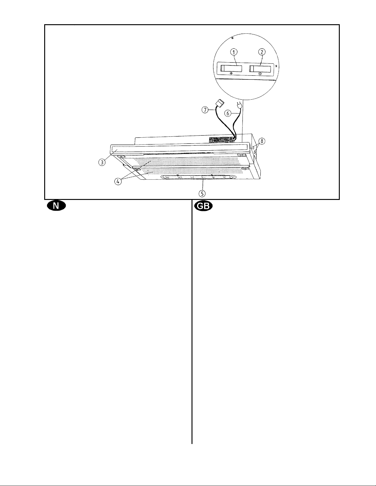
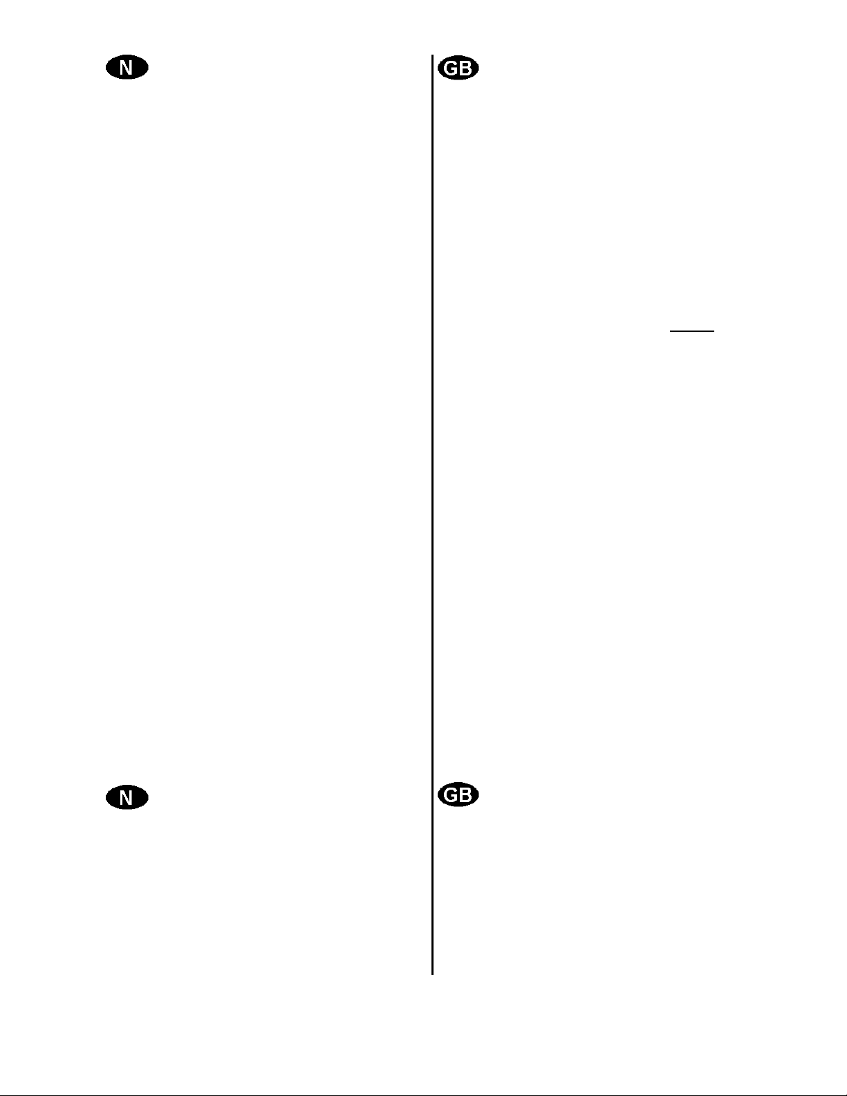
Fig. 1
BESKRIVELSE
Villavent kjøkkenhette type TSL-1/A kan
brukes sammen med alle typer Villavent
avtrekksvifter.
1. Bryter for viftehastighet/luftmengde
2. Lysbryter
3. Uttrekksdel
4. Rist m/filter
5. Deksel for arbeidslys
6. Ledning m/støpsel
7. Ledning m/hurtigkobling
8. Distansestykker og veggfester til skap
NB! Kjøkkenhetten er utstyrt med bryter for
valg av laveste viftehastighet. Bryteren,
som er merket 60 V og 90 V, sitter
innvendig bak filterplaten H (fig. 2
side 4).
60 V benyttes i forbindelse med
Villavent avtrekksanlegg i boliger med
mindre enn ca. 85 m² boflate.
90 V skal alltid benyttes i forbindelse
med Villavent varmegjenvinnere.
DESCRIPTION
The Villavent cookerhood type TSL-1/A is
constructed for use with all Villavent extract
fans and heat recovery unit, model VVX-200
Combini.
1. Fan speed control switch
2. Hob light switch
3. Telescopic section
4. Filter section
5. Cover for hob light
6. Cable with plug
7. Cable with electrical quick connector
8. Fixing holes with spacers
NB! This cookerhood is supplied with switch
for setting of minimum fan speed,
marked 60 V or 90 V. The switch is
positioned behind the filter, H (fig. 2 p.
4).
60 V is used in connection with Villavent
extract systems in homes of less than
85 m² .
90 V
always to be used when the
Villavent heat recovery system, VVX200 Combini, is installed.
3
MONTERING
Montering til ventilatorskap:
Hetten festes til undersiden av
ventilatorskapet med 4 skruer (4,5 x 16
mm). Bruk den vedlagte hullmalen
(sjablon) til å merke av de 2 festene på
innsiden av hver vegg.
NB!
Mal for høyre (right) og venstre (left)
side.
Festene bores opp til Ø2,0 mm.
Dersom kjøkkenskapene har 20 mm
veggtykkelse, fjernes de 2 sorte
distansestykkene (8 fig. 1) på hver side
av kjøkkenhetten.
Kjøkkenhetten skrus fast til overskapene
fra innsiden av hetten etter at
filterplaten, H (fig. 2), er løsnet.
Filterplaten løsnes ved å skyve de 2
plastlåsene, L (fig. 2), mot hverandre.
Når hetten er festet, settes filterplaten,
H, på plass igjen.
INSTALLATION
Mounting to ventilation cabinet
Mount the cookerhood to the underside
of the ventilation cabinet using 4
screws (4,5 x 16 mm) provided. Use
the enclosed template to mark the 2
points on the inside of each side wall.
NB!
One template for the right side and one
for the left side.
Drill Ø2,0 mm pilot holes.
If the cupboard walls are 20 mm thick,
remove the 2 black spacers (8 fig. 1) on
each side of the cookerhood.
Remove filter, H (fig. 2) by pushing the
2 filter locks inwards. Screw the
cookerhood to the side cupboard walls
from the inside of the hood.
Replace filter, H.
4
 Loading...