

Villa Sistemi Medicali STRATO 2000 Digital Service Manual
Release 30 January 2008 (Rev. 3)
STRATO 2000
STRATO 2000STRATO 2000
STRATO 2000 0051
Digital
DigitalDigital
Digital
Service Manual
Service ManualService Manual
Service Manual
SERVICE MANUAL
Revision history
(Rev. 3) STRATO 2000 Digital
Revision history
Revision historyRevision history
Revision history
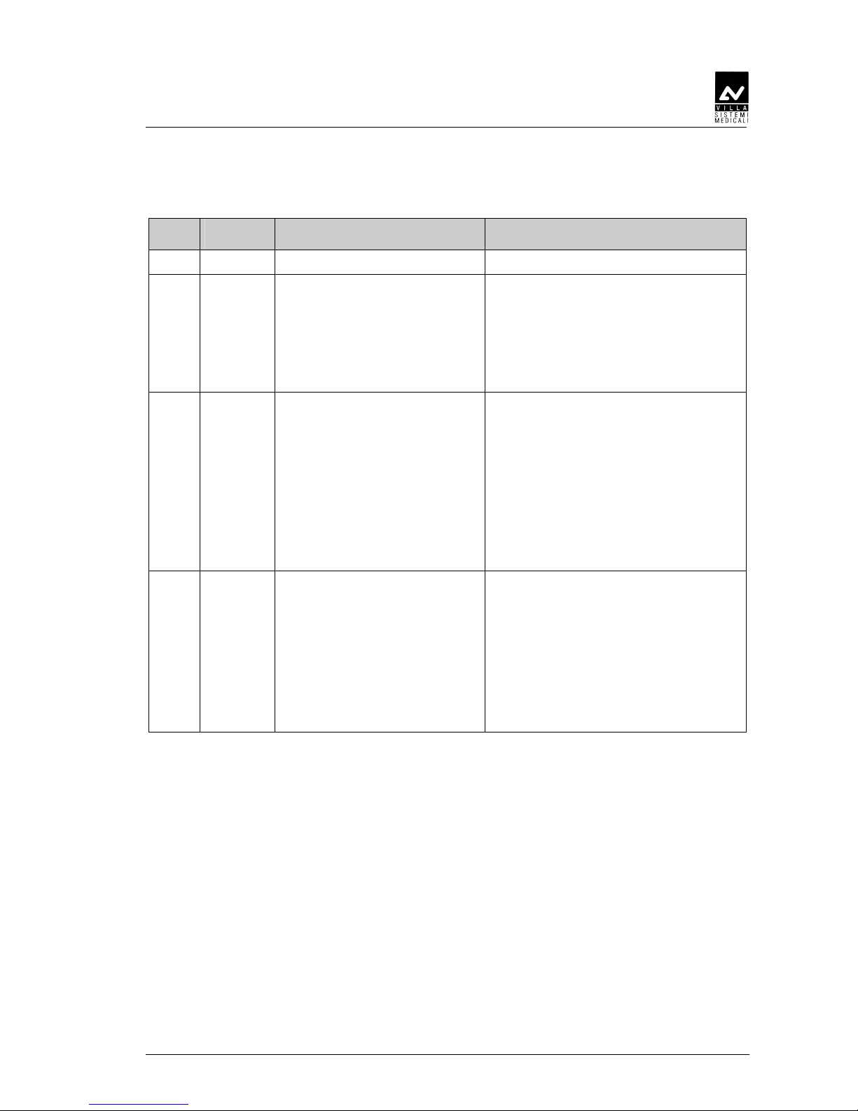
Rev. Date Page/s Modification description
0 05.05.06 - Document approval.
1 05.09.06 i, ii, iii, iv, 3-20, 3-21, 4-1,
from 6-15 to 6-24,
from 7-12 to 7-54,
from 8-1 to 8-106,
from 9-3 to 9-49,
9-85, 10-12, 10-16,
10-17, 12-2
Release of SW version 6.02 (Ceph arm
calibration procedure, Soft Tissue
Filter setting procedure, password 93 Soft Tissue Filter motor selection).
Release of SW version 6.03 (password
95 – Minimum kV value setting).
(Ref. RDM 6447, RDM 6483)
2 11.01.07 iv, 1-1, 1-2, 2-5, 3-2, 3-3,
3-4, 3-17, 3-18, 3-19,
from 4-1 to 4-5,
from 6-18 to 6-22,
7-6, 7-21,
from 7-27 to 7-31,
7-33, 7-34,
from 7-44 to 7-54,
8-2, 8-4, 8-9, 8-25, 8-87,
8-88, 8-89, 9-85, 10-10,
10-16, 10-17
Improvement of Installation,
Maintenance and servicing and
Troubleshooting procedure.
Release of “DXP 2007 Edition” kit
including Implant examination.
(Ref. RDM 6540, RDM 6566)
3 30.01.08 All New CPU board.
Improvement of Ceph arm mounting
procedure.
New Implant bite block.
Schematics and drawings update.
Spare Parts update.
Modified name from "STRATO 2000 D"
to "STRATO 2000 Digital".
(Ref. RDM 6554, RDM 6639, RDM 6666,
RDM 6679, RDM 6680, RDM 6684, RDM 6768)

SERVICE MANUAL
Revision history
STRATO 2000 Digital (Rev. 3)
THIS PAGE IS INTENTIONALLY LEFT BLANK

SERVICE MANUAL
Contents
(Rev. 3) STRATO 2000 Digital
i
Contents
1. INTRODUCTION 1-1
1.1. Icons appearing in the manual ............................................................1-2
1.2. How to contact VILLA SISTEMI MEDICALI technical service ................ 1-2
2. SAFETY INFORMATION 2-1
2.1. Warnings ............................................................................................. 2-2
2.2. Environmental risks and displacement ................................................2-5
2.3. Symbols used ...................................................................................... 2-6
3. DESCRIPTION 3-1
3.1. Identification labels and laser labels .................................................... 3-1
3.2. Function, Models and Version .............................................................3-3
3.2.1. Panoramic examination ....................................................................3-3
3.2.2. Version with cephalometric device ....................................................3-3
3.2.3. DXP (Digital Extended Program) .......................................................3-4
3.3. Parts location....................................................................................... 3-5
3.4. Location of electronic components ....................................................... 3-7
3.5. Block diagram ..................................................................................... 3-8
3.5.1. Power supply assembly.....................................................................3-9
3.5.2. CPU Board (A1) ..............................................................................3-10
3.5.3. HF Board (A2) and Tubehead..........................................................3-12
3.5.4. Keyboard .......................................................................................3-13
3.6. Control panel - Descriptions and functions........................................ 3-16
3.6.1. Key functions description ............................................................... 3-19
3.7. Service programs description ............................................................. 3-20
3.7.1. Hardware configuration password...................................................3-20
3.8. Service tools ...................................................................................... 3-21
4. TECHNICAL DATA 4-1
4.1. Applied safety regulations.................................................................... 4-6
4.2. Loading curve of the tube and cooling curve of the anode .................... 4-7
4.3. Measurement method of technical factors............................................ 4-9
4.4. Verify method of exposure parameters ............................................... 4-10
4.5. Dimensions........................................................................................ 4-14
5. PRE-INSTALLATION 5-1
5.1. Electrical setting up............................................................................. 5-2
5.2. Packaging ............................................................................................ 5-4
5.3. Space requirements ............................................................................. 5-5
5.3.1. Version without CEPH......................................................................5-5
5.3.2. Version with CEPH...........................................................................5-6

SERVICE MANUAL
Contents
STRATO 2000 Digital (Rev. 3)
ii
6. INSTALLATION 6-1
6.1. Setting of the wall ................................................................................6-2
6.2. Column mounting................................................................................ 6-3
6.3. Mounting of the rotating arm assembly................................................6-6
6.4. Mounting of the chin-rest arm ............................................................. 6-8
6.5. Digital sensor holder mounting ............................................................6-9
6.6. Mounting of ceph-arm (Optional) .......................................................6-10
6.7. Mechanical alignment check ..............................................................6-14
6.7.1. PANORAMIC alignment check ........................................................ 6-14
6.7.2. CEPH alignment check................................................................... 6-16
6.8. How to mount the coverings............................................................... 6-24
6.9. Covering mounting for the Ceph arm ................................................. 6-25
7. MAINTENANCE AND SERVICING 7-1
7.1. Verification and centering adjustment .................................................7-3
7.1.1. Axes alignment for the PANORAMIC function....................................7-3
7.1.1.1. Centering the RO(tation), AX (X-axis) and
AY (Y-axis) axes via the laser ............................................... 7-5
7.1.2. Centering the X-ray beam for the PANORAMIC function.................. 7-10
7.1.3. Axes alignment for the CEPH function ............................................ 7-14
7.1.3.1. Rotation arm alignment ....................................................7-16
7.1.3.2. Ear Centering Circles setting............................................. 7-20
7.1.3.2.1. Projection of Non-Concentric Ear Centering Circles......7-23
7.1.3.2.2. Projection of Vertically Non-Concentric Ear
Centering Circles ........................................................... 7-24
7.1.3.3. Secondary collimator centering .........................................7-25
7.1.3.4. CEPH Sensor centering ..................................................... 7-28
7.1.3.5. Soft Tissue Filter (STF) adjustment.................................... 7-32
7.2. Verify of kV and exposure time ..........................................................7-35
7.2.1. kVp ...............................................................................................7-38
7.2.2. Time ..............................................................................................7-38
7.3. mA Check .......................................................................................... 7-39
7.4. Storing of automatical exposure parameters ...................................... 7-40
7.4.1. Exposure parameter....................................................................... 7-40
7.4.2. Soft Tissue Filter............................................................................ 7-41
7.4.3. Storing parameters ........................................................................ 7-41
7.4.4. Table of pre-set anatomic parameters ............................................. 7-42
7.5. STRATO 2000 Digital Software Utilities.............................................. 7-45
8. TROUBLESHOOTING 8-1
8.1. Displayed messages ............................................................................. 8-1
8.2. LEDs.................................................................................................... 8-7
8.2.1. CPU board LED................................................................................8-8
8.2.2. H.F. board LED................................................................................ 8-9
8.2.3. Power supply LED group..................................................................8-9

SERVICE MANUAL
Contents
(Rev. 3) STRATO 2000 Digital
iii
8.3.
Service programs descriptions ........................................................... 8-10
8.3.1. Password 89 ..................................................................................8-12
8.3.2. Password 90 ..................................................................................8-13
8.3.3. Password 92 ..................................................................................8-14
8.3.4. Password 93 ..................................................................................8-15
8.3.5. Password 94 ..................................................................................8-16
8.3.6. Password 95 ..................................................................................8-17
8.3.6.1. Input ports test.................................................................8-18
8.3.6.2. Keyboard test....................................................................8-21
8.3.6.2.1. ERROR 560: One or more buttons pressed at
start-up ......................................................................... 8-22
8.3.6.2.2. ERROR 561: X-ray button released during emission ... 8-24
8.3.6.2.3. ERROR 562: X-ray button pressed during start-up or
during exam preparation ..............................................8-24
8.3.6.2.4. ERROR 563: Remote X-ray button pressed during
start-up or during exam preparation ............................ 8-24
8.3.6.3. kV / mA Piloting Circuits Test ...........................................8-25
8.3.6.3.1. ERROR 550: No voltage present on HF board ..............8-27
8.3.6.3.2. ERROR 551: Overvoltage .............................................. 8-28
8.3.6.3.3. ERROR 552: Overload................................................... 8-29
8.3.6.3.4. ERROR 553: Broken filament ....................................... 8-29
8.3.6.3.5. ERROR 554: No X-ray output....................................... 8-30
8.3.6.3.6. ERROR 555: X-ray output too long............................... 8-31
8.3.7. Password 102.................................................................................8-32
8.3.8. Password 118.................................................................................8-33
8.3.8.1. X-Axis Zero (M5 Motor)......................................................8-35
8.3.8.1.1. ERROR 500................................................................... 8-37
8.3.8.2. Y-Axis Zero (M4 Motor)......................................................8-39
8.3.8.2.1. ERROR 501................................................................... 8-42
8.3.8.3. Rotation Axis Zero (M3 Motor) ...........................................8-44
8.3.8.3.1. ERROR 502................................................................... 8-47
8.3.8.3.2. ERROR 542: Collision of the rotating arm .................... 8-49
8.3.8.3.3. ERROR 541 / ERROR 543: panoramic sensor holder
not in Panoramic / Ceph position................................. 8-49
8.3.8.3.4. ERROR 600: Reset button pressed during movement
or exam preparation...................................................... 8-49
8.3.8.4. X-Y-Rotation time-out motor zeroing..................................8-50
8.3.8.4.1. ERROR 504................................................................... 8-50
8.3.8.5. Primary Collimator motor (M7) ..........................................8-51
8.3.8.5.1. ERROR 580: Zero sensor always darkened /
ERROR 592: Unexpected limit switch activation /
ERROR 595: Motor timeout during slit primary
collimator movement / ERROR 546: Primary slit
collimator limit sensor not found ..................................8-54
8.3.8.6. Soft Tissue Filter motor (M6) .............................................8-56
8.3.8.6.1. ERROR 520: Motor time out during STF movement /
ERROR 521: STF stopped at the limit switch /
ERROR 522: Limit switch not found / ERROR 523
Soft Tissue Filter zero sensor always active...................8-58
8.3.8.7. Column motor (Column test) .............................................8-60

SERVICE MANUAL
Contents
STRATO 2000 Digital (Rev. 3)
iv
8.3.9. Password 124 ................................................................................ 8-63
8.3.9.1. Rotation axis position .......................................................8-67
8.3.9.2. Secondary Collimator motor (M8) ...................................... 8-70
8.3.9.2.1. ERROR 581 The zero sensor of ceph secondary collimator
is always active / ERROR 591 unexpected limit switch
activation CEPH secondary collimator motor / ERROR 594
CEPH secondary collimator Motor timeout / ERROR 545
CEPH secondary collimator Limit sensor not found .....8-73
8.3.9.3. CEPH sensor motor (M9) ................................................... 8-75
8.3.9.3.1. ERROR 582 The zero sensor of ceph sensor is always
active / ERROR 590 Unexpected limit switch activation
CEPH sensor motor / ERROR 593 CEPH sensor zeroing
timeout / ERROR 544 CEPH sensor motor limit sensor
not found.......................................................................8-78
8.3.9.4. Lining-up test ...................................................................8-79
8.3.9.5. Soft Tissue Filter (STF) offset............................................. 8-80
8.3.9.6. Soft Tissue Filter (STF) % of correction .............................. 8-82
8.3.10. Password 130 ................................................................................ 8-84
8.3.11. Password 143 ................................................................................ 8-85
8.4. Memory errors ...................................................................................8-87
8.4.1. ERROR 570: Checksum error on flash eprom ................................. 8-87
8.4.2. ERROR 571-572-573-574-575 .......................................................8-87
8.5. Generic errors....................................................................................8-88
8.5.1. ERROR 503 ................................................................................... 8-88
8.5.2. ERROR 506 / 515.......................................................................... 8-88
8.5.3. ERROR 507 ................................................................................... 8-88
8.5.4. ERROR 601 ................................................................................... 8-89
8.5.5. ERROR 602 ................................................................................... 8-89
8.5.6. ERROR 9xx.................................................................................... 8-89
8.6. Search and correction of possible defects in dental radiographies ......8-90
8.6.1. Defects due to incorrect position of the patient ............................... 8-90
8.6.2. Defects due to incorrect radiological data input ..............................8-91
8.6.3. Defects due to the unit................................................................... 8-92
8.7. Analysis of the problems on the panoramic examinations ..................8-93
8.7.1. Proper positioning of the patient..................................................... 8-94
8.7.2. Error due to a bad patient's positioning.......................................... 8-96
8.7.3. Images with artefacts ................................................................... 8-104
9. SCHEMATICS AND DRAWINGS 9-1
10. SPARE PARTS 10-1
11. FIXING TEMPLATE 11-1
12. APPENDIX 12-1
12.1. Appendix A: Setup parameters table .................................................. 12-1
12.2. Appendix B: Installation checklist ...................................................... 12-3
This publication can only be reproduced, transmitted, transcribed or translated into
any human or computer language with the written consent of VILLA SISTEMI
MEDICALI S.p.a.
This manual in English is the original version.
SERVICE MANUAL
Introduction
(Rev. 3) STRATO 2000 Digital
1-1
1.
1.1.
1. INTRODUCTION
INTRODUCTIONINTRODUCTION
INTRODUCTION
NOTE:
The present manual is updated for the product it is sold with in order to
grant an adequate reference in performing diagnostics and repair
operations normally carried out by the service engineer.
The manual may not reflect changes to the product not impacting service
operations.
STRATO 2000 Digital is an X-ray device for the radiographic
examinations of the maxillo-facial complex.
The device is designed to operate in conjunction with the Direct Digital
System, manufactured by Owandy – France.
Two models are available:
• PAN ONLY model equipped with a fixed primary collimator (NOT
upgradable with CEPH arm)
• PAN UPGRADABLE to DIGITAL CEPH model equipped with a slit
primary collimator that has two slots one for PAN type examinations
and the other for CEPH type examinations
The following options are available and must be ordered separately:
• Digital Extended Program (DXP); it allows the execution of the
following examinations:
– TMJ: Specific examinations for temporo-mandibular joint
– SINUS: Examination of nasal sinus
– A.D.A.: Advanced Dental Applications including: improved
orthogonal projection, frontal dentition and reduced
dose panoramic examinations
– IMPLANT: Linear Tomography for implantation procedure.
• DIGITAL CEPH (only on PAN UPGRADABLE machines); it allows the
execution of the following examinations, all available in high
resolution and normal resolution (high speed) modality:
− CEPH exam in different formats
− CARPUS exam.
This manual is limited to the description of the X-ray device; instruction
on the Digital Acquisition System are given in the relevant Manuals,
supplied with the Direct Digital Sensor.
The device must be used complying with the procedures described and
never be used for purposes different from those herewith indicated.
Please read this manual thoroughly before starting using the machine; it
is advisable to keep the manual near the device to refer to it while
operating.
SERVICE MANUAL
Introduction
STRATO 2000 Digital (Rev. 3)
1-2
STRATO 2000 Digital is an electro-medical device and it can be used only
under the supervision of a physician or of highly qualified personnel,
with the necessary knowledge on X-ray protection.
The user is liable as concerns legal fulfilment related to the installation
and the operation of the device.
1.1.
1.1.1.1.
1.1. Icons appearing in the manual
Icons appearing in the manualIcons appearing in the manual
Icons appearing in the manual
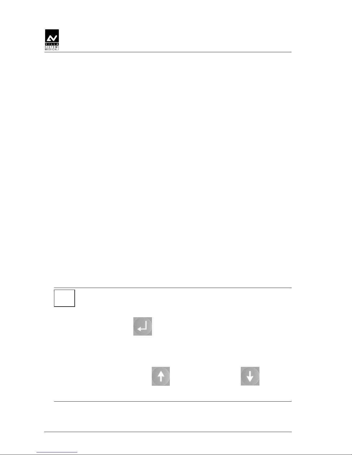
This icon indicates a NOTE; please read thoroughly the items marked
by this picture.
This icon indicates a WARNING message; the items marked by this
icon refer to the safety aspects of the patient and/or of the operator.
1.2.
1.2.1.2.
1.2. How to contact VILLA SISTEMI MEDICALI technical
How to contact VILLA SISTEMI MEDICALI technical How to contact VILLA SISTEMI MEDICALI technical
How to contact VILLA SISTEMI MEDICALI technical
service
serviceservice
service
For any technical quieries please contact the following:
• Telephone number +39 02 48859288
• Fax number +39 02 48859222
• E-mail: dentalservice@villasm.com
SERVICE MANUAL
Safety information
(Rev. 3) STRATO 2000 Digital
2-1
2.
2.2.
2. SAFETY INFORMATION
SAFETY INFORMATIONSAFETY INFORMATION
SAFETY INFORMATION
WARNING:
Please read this chapter thoroughly.
Villa Sistemi Medicali designs and builds its devices complying with the
related safety requirements; furthermore it supplies all information
necessary for a correct use and the warnings related to danger associated
with X-rays generating units.
Villa Sistemi Medicali, has not to be held responsible for:
• use of STRATO 2000 Digital different than the intended use,
• damages to the unit, to the operator, to the patient, caused both by
installation and maintenance procedures different than those
described in this manual and in the service manual supplied with the
unit, and by wrong operations,
• mechanical and/or electrical modifications performed during and
after the installation, different than those described in the service
manual.
Installation and any technical intervention must only be performed
by qualified technicians authorised by Villa Sistemi Medicali.
Only the authorised personnel can remove the covers and/or have
access to the components under tension.

SERVICE MANUAL
Safety information
STRATO 2000 Digital (Rev. 3)
2-2
2.1.
2.1.2.1.
2.1. Warnings
WarningsWarnings
Warnings
This device has not been designed for use in environments where
vapours, anaesthetic mixes flammable with air, or oxygen and nitrous
oxide can be detected.
Avoid pouring water, even accidentally, or other liquids into the device,
as this could cause short-circuits.
Before cleaning the device, be sure that main power supply has been
disconnected to the equipment. Pushing the ON/OFF button on the
basement of the equipment, it doesn’t have to switch on.
Wherever necessary, use the fit accessories, such as the leaded aprons,
to protect the patient from radiations.
While performing the radiography, no one, apart from the operator and
the patient, must remain in the room.
STRATO 2000 Digital has been built to support a continuous operation
at intermittent load; therefore please follow the described use cycles to
enable the device cooling down.
Though this unit has been designed with a quite acceptable protection
level from electromagnetic interference, it is advisable to install it at a
certain distance from electric energy transformation chambers, from
Uninterruptible Power Supply (UPS) units, from receiving-transmitting
units for amateurs use. Mobile telephones are only admitted at a
distance of more than 1,5 mt. from any component of the device.
Other medical instruments and devices that could be used in the
installation area of the device, must comply the Electromagnetic
Compatibility rules in force. Non-complying instruments, of which the
poor immunity from electromagnetic fields is well known, must be
installed at least 3 mt far from the STRATO 2000 Digital and supplied by
a different electrical line.
STRATO 2000 Digital must be off while using devices such as electrical
lancets or similar.
Please clean and disinfect, when necessary, all parts that can be in
contact with the patient.
Never try to rotate the moving arm manually when the units is
switched on, to avoid permanent damage to the unit.
After use, please replace the bite and the ear-centring devices.
SERVICE MANUAL
Safety information
(Rev. 3) STRATO 2000 Digital
2-3
The authorised technician must be sure that the unit is disconnected
from the main power supply before removing the coverings.
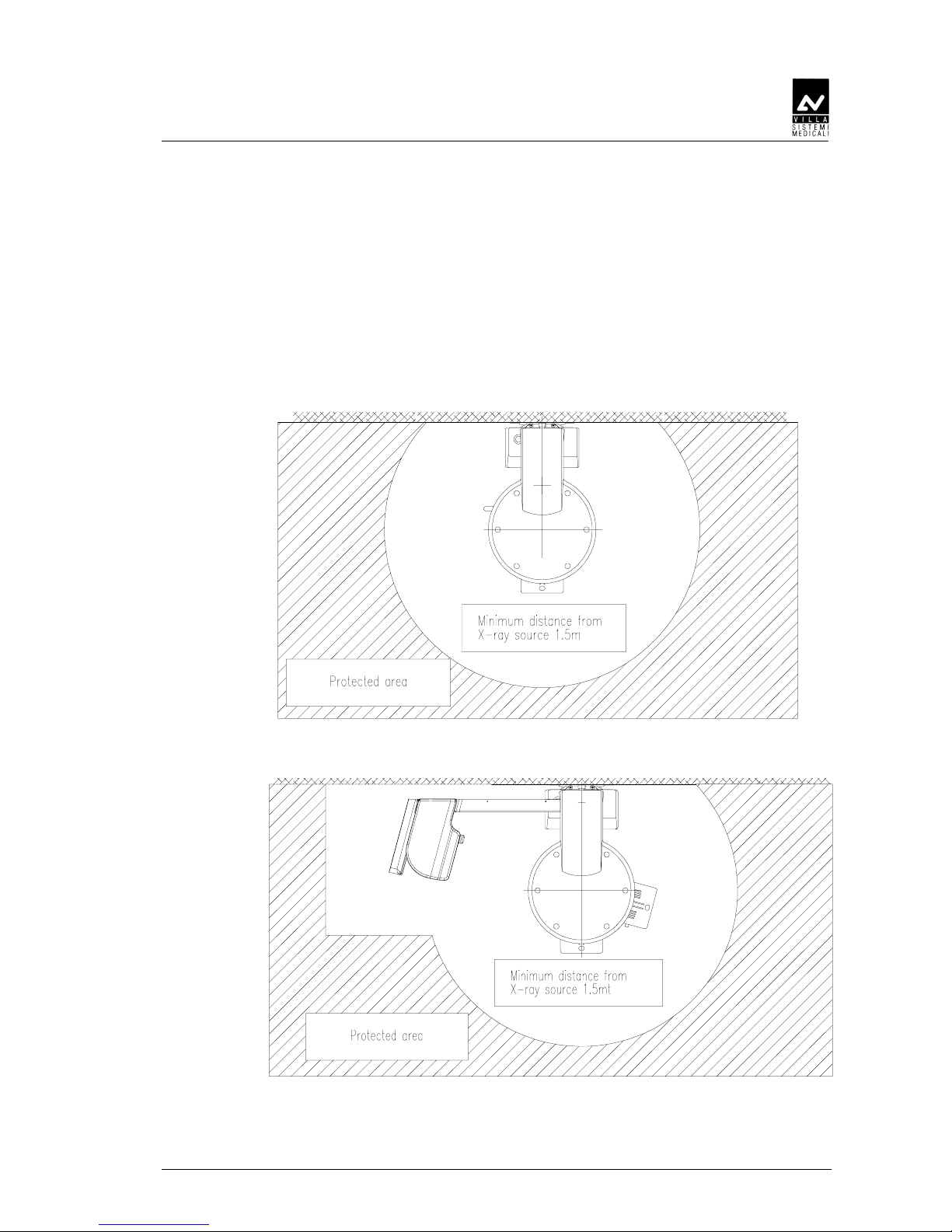
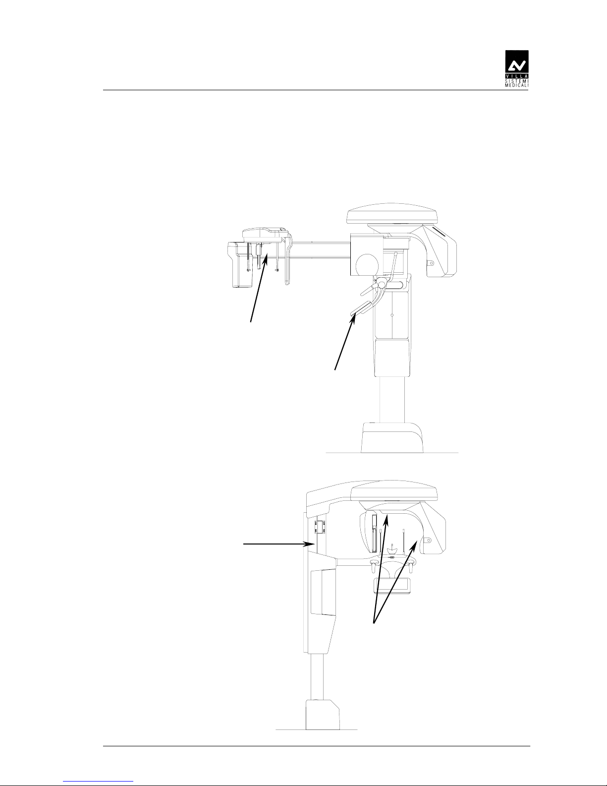
Though the X-ray quantity supplied by dental X-ray units is quite low
and distributed on a small surface, the operator must adopt the
precautions and/or fit protections for the patient and himself, during the
execution of radiography. It is advisable to control the X-ray emission
from a protected area, by means of a remote control. In case it is
necessary to operate near the patient, please stay as far as the cable of
the remote control allows it, or at least 1,5 mt far both from the X-ray
source and from the patient, as shown in the pictures below.
Figure 2-1 - Panoramic version
Figure 2-2: Cephalometric version
SERVICE MANUAL
Safety information
STRATO 2000 Digital (Rev. 3)
2-4
WARNING: PRECAUTIONS WHILE USING LASER CENTRING
DEVICES
• It is necessary an adequate illumination in the room.
• Do not look into the output windows of laser centring units.
• Do not stare at the reflections of laser pointers.
• Instruct the patient to keep his/her eyes closed as long as the laser
pointers are active.
• Before starting an examination, the patient must remove earrings,
glasses, necklaces and whatever else could reflect the laser beam or
be impressed on the radiographic image.
• Do not clean the openings of laser centring devices with tools that
could modify the optics. Necessary cleaning must be performed only
by authorised technicians. Different operations than those indicated
could cause the ejection of dangerous non-ionising radiations.
WARNING: PRECAUTIONS DURING INSTALLATION AND SERVICE
INTERVENTIONS
• Please take highest care while mounting the column at the wall and
strictly follow the instructions included in this manual.
• Before removing the covers of the supply unit located at the base of
the column, or before removing the covers of the HF generating
board, disconnect the supply to the device, both switching the main
switch and the magneto-thermal differential off, and wait at least
1 minute.
• Once removed the covers, pay the highest attention since high
tension is generated in the supply unit, and the voltage is at about
360 Vdc on the HF generator board. This is indicated by the green
LED H1. Should the LED be off, before any other intervention,
disconnect the device from the main power supply, wait at least 1
minute, then check the fuses F2 (10A) in the supply unit, or F1
(500mA) on the HF generator board (see circuit diagram code
58094016).
• Each intervention must be performed after having disconnected the
device from the main power supply and after LED H1 is OFF. It is
anyway advisable to wait at least 1 minute from the LED's switching
off.

SERVICE MANUAL
Safety information
(Rev. 3) STRATO 2000 Digital
2-5
2.2.
2.2.2.2.
2.2. Environmental risks and displacement
Environmental risks and displacementEnvironmental risks and displacement
Environmental risks and displacement
The device contains in some of its parts, materials and liquids that at the
end of the units life, must be disposed of at the fit disposal centres.
Particularly the device contains the following materials and/or
components.
• Tubehead: dielectric oil, lead, copper, iron, aluminium, glass,
tungsten.
• Control panel and remote control: iron, copper, aluminium, glass-
resin, non-biodegradable plastic material packaging.
• Column, rotating arm, and extensions: iron, lead, aluminium,
copper, glass-resin, and non-biodegradable plastic material.
SERVICE MANUAL
Safety information
STRATO 2000 Digital (Rev. 3)
2-6
2.3.
2.3.2.3.
2.3. Symbols used
Symbols usedSymbols used
Symbols used
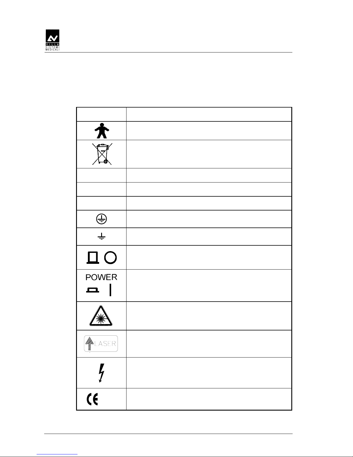
In this manual and on the STRATO 2000 Digital itself, apart from the
symbols indicated on the control panel, also the following icons are used:
Symbols Description
Device with type B applied parts
The device contains in some of its parts, materials and
liquids that at the end of the units life, must be
disposed of at the fit disposal centres
∼∼∼∼
A.C.
N
Connection point to the neutral conductor
L
Connection point to the line conductor
Protection grounding
Operation grounding
OFF ; device not connected to the main power supply
ON ; device connected to the main power supply
Laser
Laser source output
Dangerous voltage
0051
Conformity to the CE 93/42 Directive
SERVICE MANUAL
Description
(Rev. 3) STRATO 2000 Digital
3-1
3.
3.3.
3. DESCRIPTION
DESCRIPTIONDESCRIPTION
DESCRIPTION
3.1.
3.1.3.1.
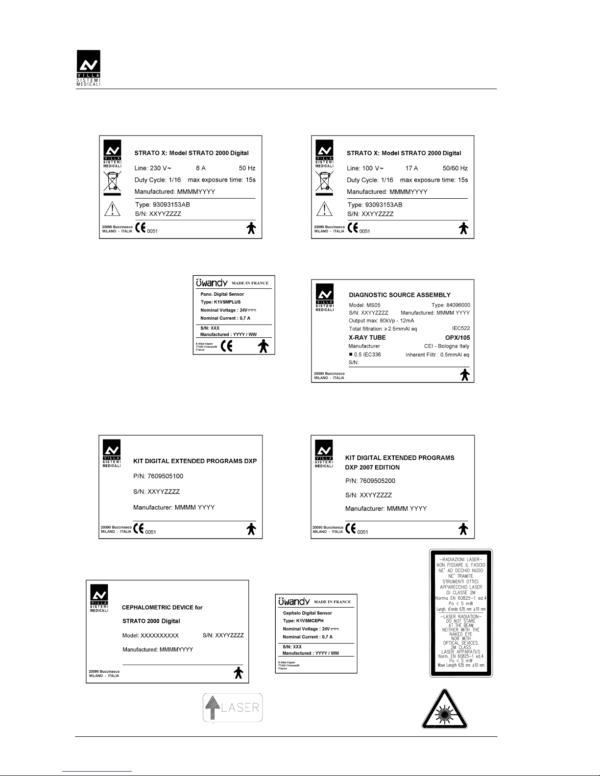
3.1. Identification labels and laser labels
Identification labels and laser labelsIdentification labels and laser labels
Identification labels and laser labels
5, 6
7
1, 2, 3, 4
8, 9
SERVICE MANUAL
Description
STRATO 2000 Digital (Rev. 3)
3-2
1a
STRATO 2000 Digital
identification label (230V version)
1b
STRATO 2000 Digital
identification label (100V version)
2
PAN Digital Sensor
identification label
3
Tube-head
identification label
4a
DXP - Digital Extension Program -
identification label
4b
DXP - Digital Extension Program -
2007 Edition
identification label
5
CEPHALOMETRIC device
identification label
6
CEPH Digital Sensor
identification label
7
Laser
Warning
label
8
(N° 2) Spot Laser
identification label
9
(N° 2) Laser
symbol label

SERVICE MANUAL
Description
(Rev. 3) STRATO 2000 Digital
3-3
3.2.
3.2.3.2.
3.2. Function, Models
Function, Models Function, Models
Function, Models and Version
and Versionand Version
and Version
3.2.1.
3.2.1.3.2.1.
3.2.1. Panoramic examination
Panoramic examinationPanoramic examination
Panoramic examination
The Panoramic and DXP tests are carried out using a single slot of the
primary collimator.
The user can select between Adult and Child and among 3 sizes and 3
dental arch types for a total of 18 combinations in Automatic selection; in
manual selection it is possible to select high voltage between 50 kV and
80 kV, in 2 kV steps and anodic current from 4 mA to 10 mA in 1 mA
steps.
The basic version performs Panoramic and Emi-panoramic (for right or
left dental arch) examinations.
3.2.2.
3.2.2.3.2.2.
3.2.2. Version with cephalometric device
Version with cephalometric deviceVersion with cephalometric device
Version with cephalometric device
The version with cephalometric device enables to perform the following
examinations:
• Panoramic with the same characteristics described for the panoramic
examinations (paragraph 3.2.1)
• Digital cephalometry for Adult and Child with 3 Sizes. For each
combination it is possible the selection between High Resolution and
Normal Resolution for up 12 combinations in automatic selection. In
the Normal Resolution modality the scanning time is lower than in
High Resolution with a greater dose reduction. The Manual mode
enables to change the high voltage from 60kV to 80kV in 2kV steps
and the anode current from 4mA to 10mA or 12mA (on the basis of
selected kV) in 1mA steps. The positioning of slit primary collimator,
secondary collimator and sensor (placed inside its cover) is automatic
according to the selected image size and exam projection; the Soft
tissue filter (STF) is motorized and can be adjusted to get the best
projection of the face profile.
• Digital Carpus exam only for Child with 3 sizes. It is possible the
selection between High Resolution and Normal Resolution for up 6
combinations in automatic selection. In the Normal Resolution
modality the scanning time is lower than in High Resolution with a
greater dose reduction. The Manual mode enables to change the high
voltage from 50kV to 80kV in 2kV steps and the anode current from
4mA to 10mA or 12mA (on the basis of selected kV) in 1mA steps.
The positioning of slit primary collimator, secondary collimator and
sensor (placed inside its cover) is automatic according to the selected
image size and exam projection.
SERVICE MANUAL
Description
STRATO 2000 Digital (Rev. 3)
3-4
3.2.3.
3.2.3.3.2.3.
3.2.3. DXP (Digital Extended Program)
DXP (Digital Extended Program)DXP (Digital Extended Program)
DXP (Digital Extended Program)
The DXP tests are carried out using the same primary collimator single
slot used for Panoramic tests.
This option adds the following examinations:
• A.D.A. (Advanced Dental Applications)
Allowing to perform improved orthogonality Panoramic examination,
frontal dentition and reduced dose panoramic examination.
The improved orthogonality Panoramic examination reduces the
overlapping of teeth in order to improve diagnosis of interproximal
caries.
The reduced dose panoramic examination allows the examination of
the dental arch exluding the temporo-mandibular joint structure.
The frontal dentition examination allows to get a better view of the
frontal part of the dental arch (aproximately from canine to canine)
thanks to a wider focal through in this region than in standard
panoramic examination.
• Sinus
Used to obtain images of the paranasal sinusis in frontal (front/back)
or lateral projection for right or left side.
• Implant
Used to obtain images of cross-sections of the dental arch, for
Implant medical treatment.
• TMJ
Used to carry out the following examinations:
– TMJ closed/open mouth in lateral projection
– TMJ in biaxial projection.
NOTE:
The code inserted into STRATO 2000 Digital to enable the optional
examinations is protected by an Unique Identification Code (UIC); in case
the UIC is not present or is faulty, an error E601 will be shown.
The Enter key "23" pressure will reset this condition, but at the
end of the start-up procedure only standard Panoramic examinations will
be enabled.
The UIC can be visualized on the system console by pressing at the same
time the Column up "27" and Column down "29" arrows.
The UIC is simply an identifier of the single STRATO 2000 Digital unit; in
case of error E601 contact Villa Sistemi Medicali Service department.
SERVICE MANUAL
Description
(Rev. 3) STRATO 2000 Digital
3-5
3.3.
3.3.3.3.
3.3. Parts location
Parts locationParts location
Parts location
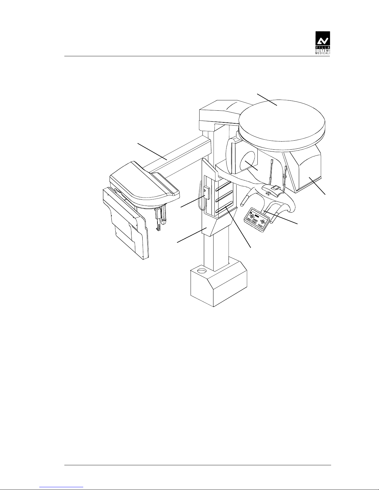
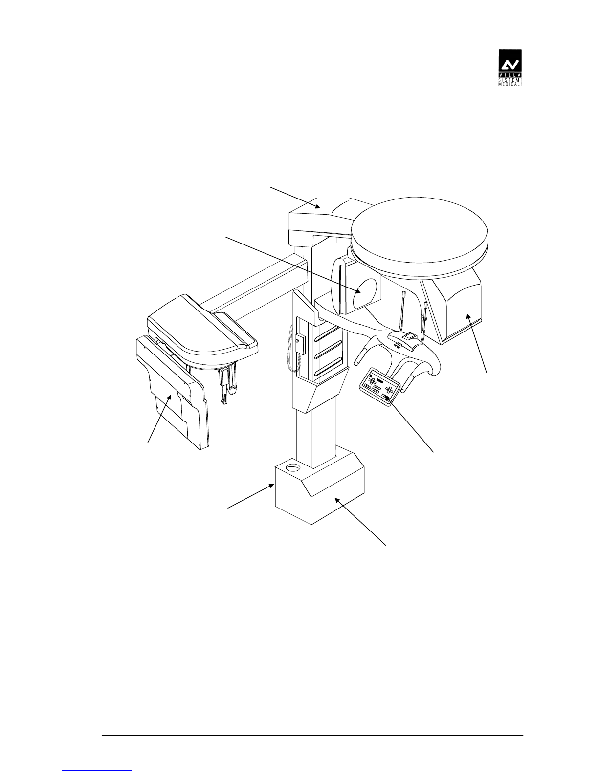
Figure 3-1
1
1 1
1 ----
Column with base equipped with electrical power part and cursor
with motorised vertical movement. The column must be fixed at the
wall by 4 dowels, two fixing the upper part and two fixing the lower.
The front part of the column is equipped with an housings closed by
two covers, within which it is possible to set 4 trays (1a) containing
the consumables (bites, rods, etc.) and options (supports, etc.).
2
2 2
2 ----
X, Y axes movement unit and rotation support, (CPU board) with
rotating arm equipped with: HF tubehead with power supply board
(2a), primary collimator and laser centring devices.
5
3
4
1
2
30
1a
2a

SERVICE MANUAL
Description
STRATO 2000 Digital (Rev. 3)
3-6
3
3 3
3 ---- Digital sensor holder.
4
4 4
4 ---- Chin support arm equipped with: control keyboard, temple support,
chin-rest, centring bite and handles. The control panel is equipped
with a soft-key keyboard, indication LED for the selected functions
and an alphanumeric two-row display for all technical, operative
and warning messages.
5555---- Cephalometric arm (optional - not available on PAN ONLY version),
including cephalometric device, digital sensor, secondary collimator
and patient centering device (with laser alignment pointer directly
from the rotating arm), positioned on the left of the column.
30
30 30
30 ---- X-ray push button equipped with extendible cable, which allows the
user to operate the unit from proper distance as required by the
safety rules.
SERVICE MANUAL
Description
(Rev. 3) STRATO 2000 Digital
3-7
3.4.
3.4.3.4.
3.4. Location of electronic components
Location of electronic componentsLocation of electronic components
Location of electronic components
Figure 3-2
COMMAND
PANEL
POWER SUPPLY GROUP
HF GENERATOR
&
TUBEHEAD
BOARD
CPU BOARD
PANORAMIC
DIRECT DIGITAL
SENSOR AND
ELECTRONICS
USB/2 CONNECTOR
CEPHALOMETRIC
DIRECT DIGITAL
SENSOR AND
ELECTRONICS

SERVICE MANUAL
Description
STRATO 2000 Digital (Rev. 3)
3-8
3.5.
3.5.3.5.
3.5. Block diagram
Block diagramBlock diagram
Block diagram
This paragraph provides a brief description, at block diagram level, of the
STRATO 2000 Digital. Aim of this paragraph is to provide a brief
description of the system. More details about the electronic circuits
which compose the system can be obtained by analyzing the schematics
provided in chapter 9.
During the description of the block diagram, please refer to Figure 3-4.
From the electrical point of view, the system can be divided into 4 main
blocks:
• Power supply assembly
• CPU board (A1)
• HF board (A2) and tubehead
• Keyboard
Each of the main blocks above listed is here after described.
For information on the electronics of the Direct Digital Sensors, make
reference to the relevant Manual.

SERVICE MANUAL
Description
(Rev. 3) STRATO 2000 Digital
3-9
3.5.1.
3.5.1.3.5.1.
3.5.1. Power supply assembly
Power supply assemblyPower supply assembly
Power supply assembly
It is located in the base of the system and is mainly composed by the
mains switch (S1), a 24Vdc 7A switching mode power supply which
supplies all circuits of the machine excluding the column motor, and a
further power supply which supplies the column motor and the enabling
circuit for X-ray emission.
A further voltage of 230Vac is directly provided to the HF board and is
aimed at suppling the HF group (A2 board and tubehead).
The power supply assembly also acts as interface with a number of
external signals and circuits like:
• Input for remote X-ray push button (S31) and output to the CPU of
the same signal.
• Outputs for an "X-ray ON" external buzzer and for the "Ready" and
"X-ray ON" lamps.
• Driving of the DC column motor (M1): this motor can be activated
either through the CPU board, in case the movement is requested by
the operator acting on the keyboard, or through the switch S2
located in the rear part of the column base. This switch can be used
to raise/lower the column during the installation phase when the
CPU has not been yet connected to the system.
• Input for the emergency column motor microswitches (S2 and S3):
these microswitches indicates the limit for the movement of the
column. If for any reason, the column goes beyond these
microswitches, the motor is de-activated by cutting the voltage.
Normally, the position of the column is also monitored by other two
microswitches (S26 and S27) that, as for all the other positioning
sensors, provide their signals to the CPU board.
The unit does not include a voltage selector circuit for the mains voltage.
Therefore, the unit is manufactured in different versions, depending on
the line voltage of the installation place.

SERVICE MANUAL
Description
STRATO 2000 Digital (Rev. 3)
3-10
3.5.2.
3.5.2.3.5.2.
3.5.2. CPU Board (A1)
CPU Board (A1)CPU Board (A1)
CPU Board (A1)
The STRATO 2000 Digital carries a dedicated CPU Board which can be
interfaced with the Digital Sensor.
It is located in the arm movement assembly on top of the unit. Main
tasks are:
• General controlling of the unit, receiving the signals from the
keyboard and from the different microswitches.
• Driving of the motors (combination of DC and stepper motors) which
compose the system.
• Monitoring the functioning of the motors through the analysis of the
signals coming from the positioning sensors.
• Driving of the HF group (HF board and tubehead) in order to provide
the X-ray doses set by the operator on the keyboard (kV and mA set
point) and in the meantime, check the functioning of this group
through the managing of the relevant alarm signals.
• Activation of the 3 luminous centering devices.
• Managing of the alarms that can be generated by anomalous
conditions present in the unit and caused by the operator or by a
fault.
The CPU board is based on a 32 bit Motorola Microprocessor MC68332,
mounted on a piggy-back PCB, which also includes:
• 512 Kbytes of Flash EPROM, containing the software and the system
configuration data (2 EPROM's for ODD and EVEN data)
• 512 Kbytes of RAM, (2 chips, ODD and EVEN)
• 12 bit, 8 channel serial A to D converter
• 2 channel, 8 bit serial D to A converter
• three bus transceivers
• a 32 kHz quartz
• other logic and passive components.
The CPU board also includes a number of input/output channels
necessary for the functioning of the system and stepper motors driving
stages based on integrated motor drivers. Each of these motors is
associated to positioning sensors that monitor their functioning. The
signals of these sensors is fed back to the CPU board, except the signals
of microswitches S2 and S3 (column motor) that, as already described
are fed back to the power supply assembly.
The number and the type of sensors depend on the function of each
motor, in general, microswitches are used.
Depending on the physical location of the motors on the machine, their
signals and the ones of the relevant positioning sensors are routed
directly to the CPU through dedicated cables, or passing through
interconnection boards located nearby.

SERVICE MANUAL
Description
(Rev. 3) STRATO 2000 Digital
3-11
The transmission of the motion from the motor to the relevant movement
assemblies is achieved through toothed belts (rotation motor, X axis
motor and Y axis motor) or through actuators (column motor and
primary collimator, soft tissue filter, secondary collimator and ceph
sensor).
The functioning of the different motors and relevant positioning sensors
can be tested through the use of the Service Programs (Passwords). For
more details, please refer to paragraph 8.3.
The circuits of the CPU board are supplied starting from the +24Vdc
provided by the Power supply assembly and generating on board the
requested voltages (+5V, +5VS and +12VS). Three LED's on the board
indicate the presence of these 3 voltages (+5V=LED H11,
+12VS=LED H13, +5VS=LED H10).

SERVICE MANUAL
Description
STRATO 2000 Digital (Rev. 3)
3-12
3.5.3.
3.5.3.3.5.3.
3.5.3. HF Board (A2) and Tubehead
HF Board (A2) and TubeheadHF Board (A2) and Tubehead
HF Board (A2) and Tubehead
The HF board and the tubehead are located on the rotating arm, very
close to each other. The power supply voltage (230Vac) is directly
provided by the Power supply assembly, passing through a filtering box
having the function to rectify the input voltage to generate a 360Vdc
voltage.
Dedicated switching circuits, directly located on the board, generate the
voltage used on the board itself (+12V/-12V).
Managing of the HF board is done by the main CPU board of the unit.
The high frequency (HF) circuit is based on an inverter circuit working at
the frequency about 30kHz, which drives the tubehead through an
output stage based on IGBT components.
The HF board receives the signals concerning the X-ray dose to provide
(kV and mA), directly from the CPU board. The HF board provides to the
tubehead the voltages that drive the high voltage transformers that then
drive anode and filament of the X-ray tube, also giving the relevant
timing.
The tubehead is composed by the radiogenic tube (CEI OPX/105)
inserted in a sealed container, together with the high voltage
transformers, filled with dielectric oil.
Checking of proper functioning of the X-ray emitting system is achieved
through the analysis of feed back signals generated inside the tubehead
and transmitted to the HF board. Possible anomalous conditions are then
communicated to the CPU board which in turn generates error codes to
alert the operator.

SERVICE MANUAL
Description
(Rev. 3) STRATO 2000 Digital
3-13
3.5.4.
3.5.4.3.5.4.
3.5.4. Keyboard
KeyboardKeyboard
Keyboard
The keyboard is the interface with the operator, and is composed by the
following items:
• Matrix of keys, constituted by microswitches with short stroke,
necessary to activate the different available functions
• Signalling LED integrated in the touch panel
• LCD display equipped with back-light, composed by a matrix of 16
characters and 2 rows
• Keyboard PCB.
The keyboard PCB is directly connected to the CPU board which controls
it. The language of the messages shown on the display can be selected
among 5 different options (English, Italian, French, German and
Spanish). The language selection is only available for the messages
dedicated to the user. The messages relative to the service programs
(Password) are always in English.
SERVICE MANUAL
Description
STRATO 2000 Digital (Rev. 3)
3-14
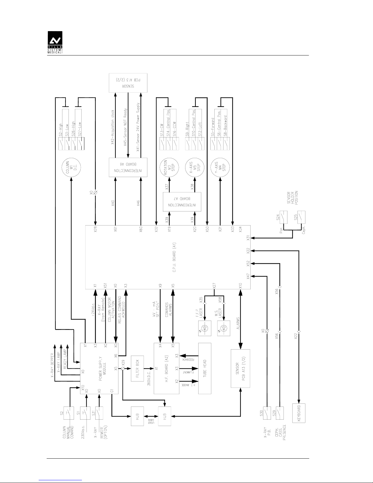
Figure 3-3 - Block diagram PAN only version
SERVICE MANUAL
Description
(Rev. 3) STRATO 2000 Digital
3-15
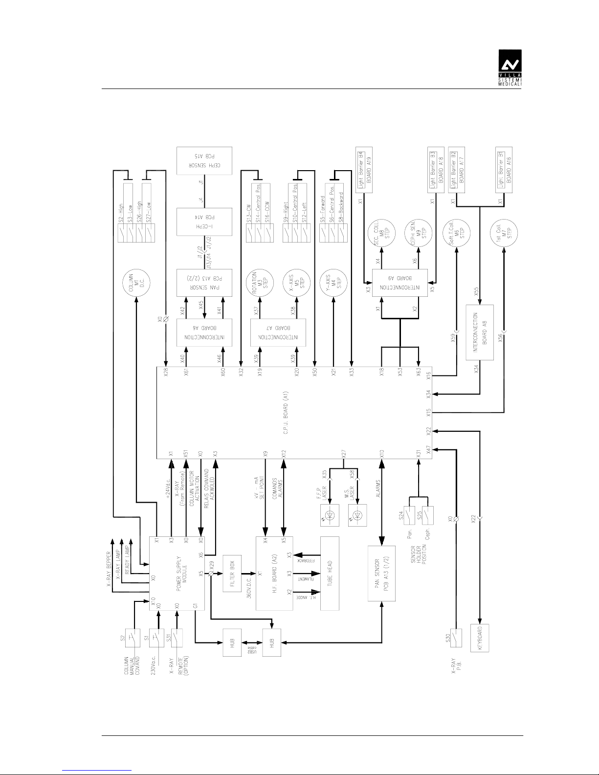
Figure 3-4 – Block diagram CEPH version
 Loading...