

Villa Sistemi Medicali ROTOGRAPH-D Service Manual
Release 11 November 2013 (Rev. 5)
ROTOGRAPH
ROTOGRAPHROTOGRAPH
ROTOGRAPH----D
DD
D
(120V version)
(120V version)(120V version)
(120V version)
Service Manual
Service ManualService Manual
Service Manual
SERVICE MANUAL
Revision history
(Rev. 5) ROTOGRAPH-D (120V)
Revision history
Revision historyRevision history
Revision history Manual code 6908917800
Manual code 6908917800 Manual code 6908917800
Manual code 6908917800
Rev. Date Page/s Modification description
0 26.10.05 - Document approval.
1 16.11.06 from 6-3 to 6-6,
7-32, 7-33,
10-4, 10-10
Installation and adjustment procedure
improvement.
Spare Parts update.
(Ref. RDM 6269, RDM 6446, RDM 6462, RDM 6540)
2 20.09.07 i, ii, from 5-2 to 5-6,
6-6, from 7-9 to 7-47,
9-15, 9-23, 9-25,
9-27, 10-4
Modified Chapter 7: Parts replacements
paragraph added, improvement in
Troubleshooting.
Added NOTE with indication that the
device is supplied as unit to be installed
permanently (EN60601-1 – paragraph 19).
Schematics update.
(Ref. RDM 6620, RDM 6660, RDM 6683, RDM 6701)
3 24.01.08 7-39 New arm rotation motor.
(Ref. RDM 6751)
4 15.07.11 All Release version Restyle 2011.
5 11.11.13 3-2, 4-2,
from 9-4 to 9-8,
from 9-13 to 9-25,
10-2, 10-6, 10-7
Inclusion of magnification factors after
software correction.
Digital Sensor identification label update.
Schematics and drawings update.
Spare Parts update.
(Ref. RDM 6746, RDM 7353, RDM 7575, RDM 7688,
RDM 7809, RDM 7857)

SERVICE MANUAL
Revision history
ROTOGRAPH-D (120V) (Rev. 5)
THIS PAGE IS INTENTIONALLY LEFT BLANK

SERVICE MANUAL
Contents
(Rev. 4) ROTOGRAPH-D (120V)
i
Contents
1. INTRODUCTION 1-1
1.1 Icons appearing in the manual ............................................................ 1-1
1.2 How to contact VILLA SISTEMI MEDICALI technical service................ 1-2
2. SAFETY INFORMATION 2-1
2.1 Warnings ............................................................................................. 2-2
2.2 Environmental risk and disposal .........................................................2-3
2.3 Symbols used ...................................................................................... 2-4
3. DESCRIPTION 3-1
3.1 Identification labels ............................................................................. 3-1
3.2 Description .......................................................................................... 3-3
4. TECHNICAL FEATURES 4-1
4.1 Standards and regulation .................................................................... 4-4
4.2 X-ray tubehead curves ........................................................................ 4-5
4.3 Technical factors measuring method ................................................... 4-7
4.4 Overall dimension................................................................................ 4-8
5. PRE-INSTALLATION 5-1
5.1 Electrical requirements ....................................................................... 5-2
5.2 Environmental condition ..................................................................... 5-4
5.3 Unpacking ...........................................................................................5-4
5.4 Space requirements ............................................................................. 5-5
6. INSTALLATION 6-1
6.1 Version with legs ................................................................................. 6-2
6.2 Version without legs .......................................................................... 6-10
6.3 How to mount the coverings .............................................................. 6-14
7. CHECKOUT AND ADJUSTMENTS 7-1
7.1 Power up ............................................................................................. 7-2
7.2 Set-up ................................................................................................. 7-3
7.2.1 Activation of the set-up programs ....................................................... 7-3
7.2.2 Modification of the values of the "Software DIP-Switches"....................7-4
7.2.3 Non-volatile memory reset .................................................................. 7-8
7.3 Checking and adjusting the AC voltage ............................................... 7-9
7.3.1 Check of line voltage regulation ........................................................ 7-10

SERVICE MANUAL
Contents
ROTOGRAPH-D (120V) (Rev. 4)
ii
7.4 Checking the output current (mA) .....................................................7-11
7.4.1 First solution (rotating arm in movement)......................................... 7-11
7.4.2 Second solution (rotating arm blocked) ............................................. 7-12
7.5 Checking and centering adjustment of the X-ray beam .....................7-13
7.5.1 Alignment of the X-ray beam for the PANORAMIC mode.................... 7-14
7.5.1.1 Oblique regulation ............................................................ 7-15
7.5.1.2 Vertical regulation ............................................................ 7-16
7.5.1.3 Horizontal regulation ........................................................ 7-17
7.6 Angle (A…) and Time (T…) control......................................................7-18
7.7 Set the default angles and times ........................................................ 7-20
7.7.1 PAN-ADULT ..................................................................................... 7-21
7.7.2 PAN-CHILD...................................................................................... 7-23
7.7.3 TMJ1 and TMJ2 - ADULT and CHILD............................................... 7-24
7.7.4 Verification of Panoramic centering and symmetry ............................ 7-26
7.8 Error messages and Troobleshooting ................................................. 7-29
7.8.1 Line voltage too high / too low ......................................................... 7-31
7.8.2 Impossible to regulate the line voltage .............................................. 7-32
7.8.3 Memory data corrupted. Call Technical Assistance............................ 7-33
7.8.4 "NO ANSWR" ................................................................................... 7-33
7.8.5 Out of Order N°1! Call Technical Assistance...................................... 7-34
7.8.6 Asymmetric images (incorrect rotation time) ..................................... 7-34
7.9 Replacing parts.................................................................................. 7-35
7.9.1 Potentiometer replacement/calibration ............................................. 7-35
7.9.2 Rotation Start / Stop Microswitch replacement................................. 7-38
7.9.3 Arm Rotation Motor / Power Board A1 replacement .......................... 7-40
7.9.4 CPU Board A2 replacement .............................................................. 7-42
7.10 Checking (safety) hardware timers .....................................................7-43
7.11 System reconfiguration after testings ................................................ 7-44
8. MAINTENANCE 8-1
9. SCHEMATICS AND DRAWINGS 9-1
9.1 Key to general diagram of the ROTOGRAPH-D.....................................9-2
10. SPARE PARTS 10-1
This publication can only be reproduced, transmitted, transcribed, or translated
into any human or computer language with the written consent of Villa Sistemi
Medicali S.p.a.
This manual in English is the original version.
SERVICE MANUAL
Introduction
(Rev. 4) ROTOGRAPH-D (120V)
1-1
1.
1.1.
1. INTRODUCTION
INTRODUCTIONINTRODUCTION
INTRODUCTION
NOTE:
The present manual is updated for the product it is sold with in order to
grant an adequate reference in performing diagnostics and repair
operations normally carried out by the service engineer.
The manual may not reflect changes to the product not impacting service
operations.
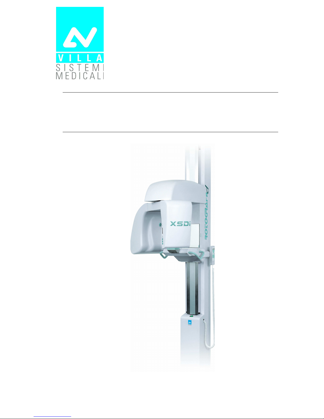
ROTOGRAPH-D, manufactured by Villa Sistemi Medicali, is a radiological
device which allows to carry out radiological examinations of the dento
maxillo facial complex, when used in conjunction with the digital image
acquisition system QuickVision manufactured by Owandy.
ROTOGRAPH-D is available in a single version for the execution of:
•
PANORAMIC examination
•
Temporo-Mandibular Joint (TMJ) examination
•
SINUS examination.
This manual provides to the operator the instructions for proper and safe
use of the appliance.
The appliance must be used strictly following the procedures described
in this manual and never for activities other than those for which it was
designed.
Before using the appliance, we recommend to read carefully this manual.
Keep it in a safe place near the unit for future reference.
ROTOGRAPH-D is an electromedical appliance and may be used only
under medical supervision, i.e. with the supervision of highly qualified
persons with the necessary know-how regarding X-ray protection.
The user is responsible for complying with the legal requirements
regarding the installation and operation of the equipment.
1.1
1.11.1
1.1 Icons appearing in the manual
Icons appearing in the manualIcons appearing in the manual
Icons appearing in the manual
Indicates a “NOTE”; the utmost attention shall be devoted to the
reading of paragraphs marked by this icon.
Indicates a “WARNING”; paragraphs marked with this icon cover
patient and/or operator safety aspects.

SERVICE MANUAL
Introduction
ROTOGRAPH-D (120V) (Rev. 4)
1-2
1.2
1.21.2
1.2 How to contact VILLA SISTEMI MEDICALI
How to contact VILLA SISTEMI MEDICALI How to contact VILLA SISTEMI MEDICALI
How to contact VILLA SISTEMI MEDICALI
technical service
technical servicetechnical service
technical service
For any technical queries please contact the following:
• Telephone number +39 02 48859.1
• Fax number +39 02 48859222
• E-mail: dentalservice@villasm.com
SERVICE MANUAL
Safety information
(Rev. 4) ROTOGRAPH-D (120V)
2-1
2.
2.2.
2. SAFETY INFORMATION
SAFETY INFORMATIONSAFETY INFORMATION
SAFETY INFORMATION
WARNING:
Read this chapter very carefully.
VILLA SISTEMI MEDICALI designs and manufactures equipment in
compliance with safety requirements; moreover, it provides all the
necessary information for correct utilization as well as warnings related
to risks associated to X-ray generators.
Villa Sistemi Medicali shall not be responsible for:
• any use of the ROTOGRAPH-D different from that for which it has
been designed,
• any damage to the equipment, the operator or the patient caused
either by incorrect installation and maintenance not compliant with
the procedures contained in the relevant user’s and installation
manuals provided with the equipment, or by incorrect operation
techniques,
• any mechanical and/or electrical changes effected during or after
installation, different from those reported in the service manual.
Only qualified service personnel, authorized by VILLA SISTEMI
MEDICALI is allowed to perform technical interventions on the
equipment.
Only authorized personnel is allowed to remove the tubehead from
its support and access the internal components.

SERVICE MANUAL
Safety information
ROTOGRAPH-D (120V) (Rev. 4)
2-2
2.1
2.12.1
2.1 Warnings
WarningsWarnings
Warnings
The system has not been designed to be used in presence of vapours,
anaesthetic mixtures that are flammable with air, or oxigen or nitrous
oxide.
Ensure that water or other liquids do not get into the machine so as to
prevent short-circuits and corrosion.
Always disconnect from mains before cleaning the machine.
Where necessary, accessories such as lead-sealed aprons must be used
to protect the patient from radiations.
Only the patient and the operator may remain in the room during the
execution of the radiography examination.
ROTOGRAPH-D has been developed for continuous use with intermittent
load. The prescribed operating cycles to allow the heat accumulated by
the radiogenic source to be discharged must be observed.
Although the appliance has been designed to have a reasonable degree of
protection from electromagnetic interference, it must be installed at a
certain distance from electricity transformer rooms, static continuity
unit, portable two-way hand radios and cellular phones. The latter may
only be used at a distance of over 1.5 meters from all elements of the
machine.
All instruments or equipment for professional use and used near the
machine must be in conformance to the electromagnetic compatibility
standards.
Nonconforming instruments whose low immunity to electromagnetic
fields is known must be installed at least 3 meters away from the
ROTOGRAPH-D and be powered via an independent electric line.
ROTOGRAPH-D must be switched off during the entire period of use of
ESU (Electro Surgery Units) units or similar equipment.
Clean or eventually disinfect the chin support, positioning handles,
temples clamp support and any other part that may come in touch with
the patient.
At the end of the examination, replace the bite.
SERVICE MANUAL
Safety information
(Rev. 4) ROTOGRAPH-D (120V)
2-3
Although the X-ray dosage supplied by dental radiology appliances is on
average low and distributed over a relatively small surface, the operator
must take the necessary precautions and/or follow the safety procedures
for both himself and the patient during an exposure. We recommend
that the X-ray activation always be commanded from an X-ray protected
area via remote control. If it is necessary to operate the exposure near
the patient, remain at the maximum distance allowed by the remote
control cable in the direction opposite to the emission of the rays, at a
distance of at least 78 ¾ inches (2 meters) from both the radiation
source and patient.
2.2
2.22.2
2.2 Environmental risk and disposal
Environmental risk and disposalEnvironmental risk and disposal
Environmental risk and disposal
A number of machine parts contain materials and liquids that upon
completion of the machine’s life cycle must be disposed of at recovery
centers established by the local health units.
The machine contains the following materials and/or components:
• Tubehead: dielectric oil, lead, copper, iron, aluminum, glass,
tungsten, beryllium
• Control box and remote control: iron, copper, glass resin, non-
biodegradable plastic casings
• Column, rotating arm, extensions: iron, lead, aluminum, copper,
non-biodegradable plastic materials, glass resin.
WARNING:
Before disassembling the parts, lock the counterweight of the slider
inserted in the column. This is possible only after having slid the slider
all the way down and inserted a pin approximately 25cm in length and
8mm in diameter. Once the pin has been inserted, move the slider
towards the top until the counterweight rests on the pin. Remove the
tubehead and some of the parts of the rotating arm. Holding the slider
firmly, remove the pin and move the slider towards the top to the
metallic stop of the column. At this point, remove all the remaining
parts.
SERVICE MANUAL
Safety information
ROTOGRAPH-D (120V) (Rev. 4)
2-4
2.3
2.32.3
2.3 Symbols used
Symbols usedSymbols used
Symbols used
Symbol Description
Equipment with Type B applied parts (according to
IEC 60601-1)
A number of machine parts contain materials and
liquids that upon completion of the machine’s life
cycle must be disposed of at recovery centers
established by the local health units
∼∼∼∼
Alternating Current
N Connection to neutral conductor
L Connection to line conductor
Protection ground
Functional ground
OFF ; equipment not connected to power line
ON ; equipment connected to power line
Warning: read the documentation provided with the
unit
SERVICE MANUAL
Description
(Rev. 5) ROTOGRAPH-D (120V)
3-1
3.
3.3.
3. DESCRIPTION
DESCRIPTIONDESCRIPTION
DESCRIPTION
3.1
3.13.1
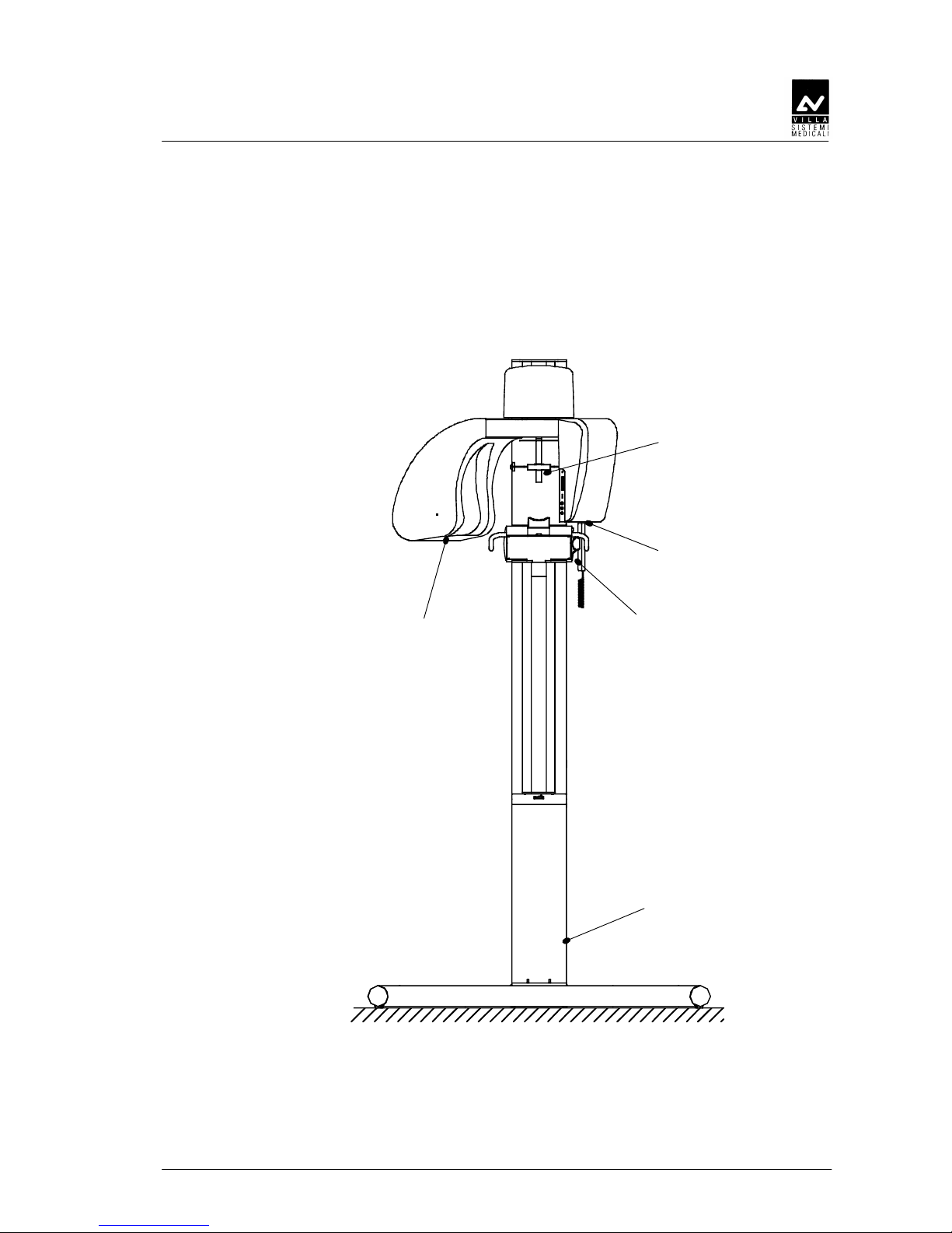
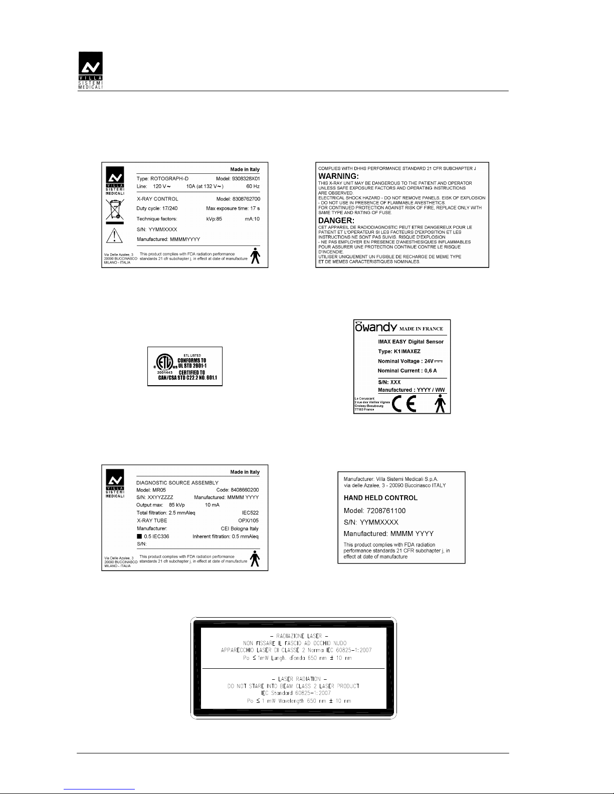
3.1 Identification labels
Identification labelsIdentification labels
Identification labels
1
3
2
4
5
SERVICE MANUAL
Description
ROTOGRAPH-D (120V) (Rev. 5)
3-2
1a
ROTOGRAPH-D
label
1b
WARNING label
1c
ETL certification
label
2
Digital Sensor
identification label
3
Tube head
identification label
4
Remote control
identification label
5
Laser WARNING
label

SERVICE MANUAL
Description
(Rev. 5) ROTOGRAPH-D (120V)
3-3
3.2
3.23.2
3.2 Description
DescriptionDescription
Description
ROTOGRAPH-D has been designed to perform the following
examinations:
• Panoramic examination
• "SINUS" examination of the paranasal sinus
• Examination of the Temporo-Mandibular Joints (TMJ) with open or
closed mouth on a single image
All the allowed examination may be made with different parameters
according to the setting of the remote-control (please refer to Chapter 6
of User’s Manual).
ROTOGRAPH-D is controlled by a soft touch console and equipped with
an alphanumeric digital display for a clear indication of the working
parameters and operative messages.
The operative cycle is entirely run by a microprocessor, controlling its
different modes: from programming of the emission parameters
according to the chosen examination and the patient's size, to the
voltage fluctuation and to the notification of possible anomalies, failures
or errors.
The excellent quality radiographs thus obtained is the result of a clever
design based upon the pseudo-elliptic rotation system, the original light
beam-luminous cross pattern centering system, the use of green emiting
Rare Earth Intensifying screens and most of all the small dimension of
the focal spot.
This particular rotation system allows an orthogonal imaging of all teeth
and wide image layer with an optimum focused zone of 10 mm for the
incisors and 20 mm for the molars.
ROTOGRAPH-D, besides operating in the programmed mode, can also
operate in the manual personalized mode by modification of the
parameters, as described in chapter 5.
In the Panoramic and TMJ modes, with all interlock enabled, it is
possible to activate the TEST push button (31) (see Figure 7-7 at the end
of the manual).
The TEST functioning mode allows the operator to check the
functionality of the selected examination cycle or to show to the patient
the examination he will undergo (including all movements of the
machine) without emitting X-rays.
The TEST push button as X-RAY button is a "dead man" button, which
means thus if it is released during the examination cycle, the latter is
interrupted stopping the movements in progress. To re-start the cycle
first reset the unit by means of the key "32" (Figure 7-7), than start again
the function which was interrupted.

SERVICE MANUAL
Description
ROTOGRAPH-D (120V) (Rev. 5)
3-4
THIS PAGE IS INTENTIONALLY LEFT BLANK
SERVICE MANUAL
Technical features
(Rev. 5) ROTOGRAPH-D (120V)
4-1
4.
4.4.
4. TECHNICAL FEATURES
TECHNICAL FEATURESTECHNICAL FEATURES
TECHNICAL FEATURES
General characteristics
Equipment ROTOGRAPH-D
Manufacturer VILLA SISTEMI MEDICALI
Buccinasco (MI) Italy
Class Class II according to 21 CFR
sub-chapter J.
Class I with type B applied parts
according to IEC.
Degree of protection IP20
Rated line voltage
120V ± 10%
Line frequency 60Hz
Max line current at nominal voltage 10A rms momentary; 0.5A stand-by
Maximum power 1.15 kVA @ 108V
Power fuse 10A T
Command fuse 0.5A T
Filament fuse 0.315A F
Line voltage regulation
≤ 3% at 108V
Compensation of the mains voltage
fluctuation
automatic
Apparent line resistance
0.5 Ω max
High voltage 60-85 kV (5 kV steps)
KV accuracy
± 10% @ 120V ± 10%
Anodic current 10 mA
Anodic current accuracy
± 1.5 mA @ 120V ± 10%
Exposure time (Panoramic) 17s adult
14s child
Exposure time (TMJ1 + TMJ2) 10.4s adult
9.4s child
Exposure interval (PAN & TMJ) 240s (1:16 duty cycle)
Height of irradiated area on sensor 5 ⅝" (143 mm)
NOTE:
Due to technology used to compensate the line voltage fluctuations, the
maximum of line current absorbed from the line is at the lowest voltage
(108V).
SERVICE MANUAL
Technical features
ROTOGRAPH-D (120V) (Rev. 5)
4-2
Image magnification
Geometric
magnification
Magnification after
software correction
Panoramic and TMJ 1.2 : 1 1 : 1 (*)
(*) WARNING:
The declared image magnification value is valid after proper software
calibration.
Tubehead features
Type MR05
Manufacturer VILLA SISTEMI MEDICALI
Buccinasco (MI) Italy
Max peak tube potential 85 kV
Nominal power 0.630 kW (85kVp, 10mA)
Total filtration ≥ 2.8 mm Al eq. at 85 kV
Insulation Oil bath
Cooling Ambient
Leakage radiation at 1 m < 0.25 mGy/h
(85 kV, 10mA, 1:16 duty cycle)
Maximum power 85 kVp, 10mA
Type of circuit Single-phase, self-rectifying
X-ray tube features
Manufacturer CEI – Bologna Italy
Type CEI OPX/105
Focus 0.5 IEC 336
Inherent filtration 0.5 mm Al eq.
Anode tilt 5°
Anode material Tungsten
Nominal voltage 105 kVp
Filament maximum current 4A
Filament maximum voltage 8V
Anode thermal capacity 30 kJ
SERVICE MANUAL
Technical features
(Rev. 5) ROTOGRAPH-D (120V)
4-3
Laser centring device
2 laser beams are used for the patient positioning; beams align mid Sagittal and
Frankfurt planes (please refer to relevant paragraphs for detailed explanation).
Wave length 650 nm ± 10 nm
Divergence < 2.0 mRad
Optical power ≤ 1 mW
Classification Class 2 laser product according to IEC
Standard 60825-1:2007
Weight of apparatus and parts
Slider net weight 108 lbs (49 kg)
Column net weight 106 lbs (48 kg)
Tubehead net weight 42 lbs (19 kg)
Control unit net weight 62 lbs (28 kg)
Slider counterweights net weight 150 lbs (68 kg)
Environmental conditions
Maximum operating temperature range
+50°F ÷ +104°F (+10° ÷ +40°C)
Operating relative humidity range
30% ÷ 75%
Transportation and storage temperature
range
-4°F ÷ +158°F (-20° ÷ +70°C)
Maximum transportation and storage
relative humidity
< 90% non condensing
Minimum atmospheric pressure for
transportation and storage
630 hPa

SERVICE MANUAL
Technical features
ROTOGRAPH-D (120V) (Rev. 5)
4-4
4.1
4.14.1
4.1 Standards and regulation
Standards and regulationStandards and regulation
Standards and regulation
The ROTOGRAPH-D equipment is manufactured according to the
following standards:
21 CFR subchapter J
• General safety:
IEC 60601-1
IEC 60601-2-7
IEC 60601-2-28
IEC 60601-2-32
UL 2601
• Electromagnetic compatibility
IEC 60601-1-2
• Protection from radiation
IEC 60601-1-3
SERVICE MANUAL
Technical features
(Rev. 5) ROTOGRAPH-D (120V)
4-5
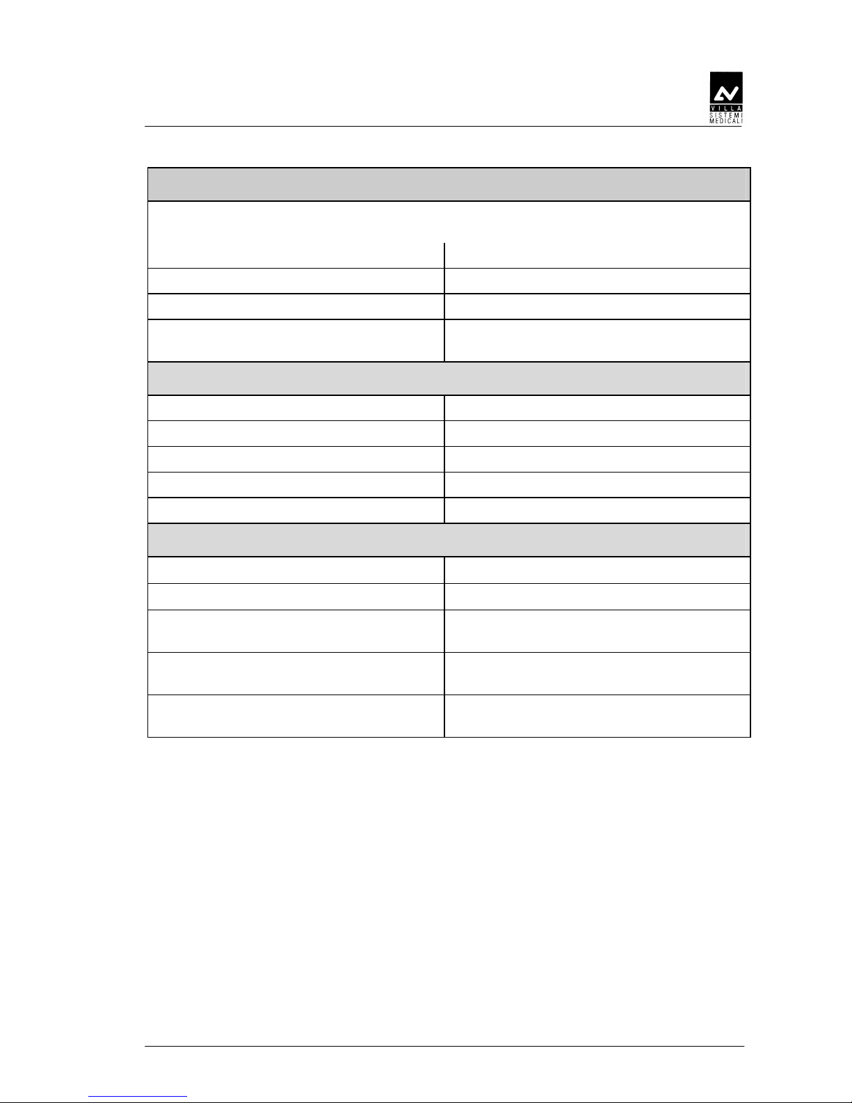
4.2
4.24.2
4.2 X
XXX---
-ray tubehead curves
ray tubehead curvesray tubehead curves
ray tubehead curves
Tube "CEI
Tube "CEI Tube "CEI
Tube "CEI ---- OPX/105" (0.5x0
OPX/105" (0.5x0 OPX/105" (0.5x0
OPX/105" (0.5x0.5)
.5).5)
.5)
Loading chard
Anode cooling chard
SERVICE MANUAL
Technical features
ROTOGRAPH-D (120V) (Rev. 5)
4-6
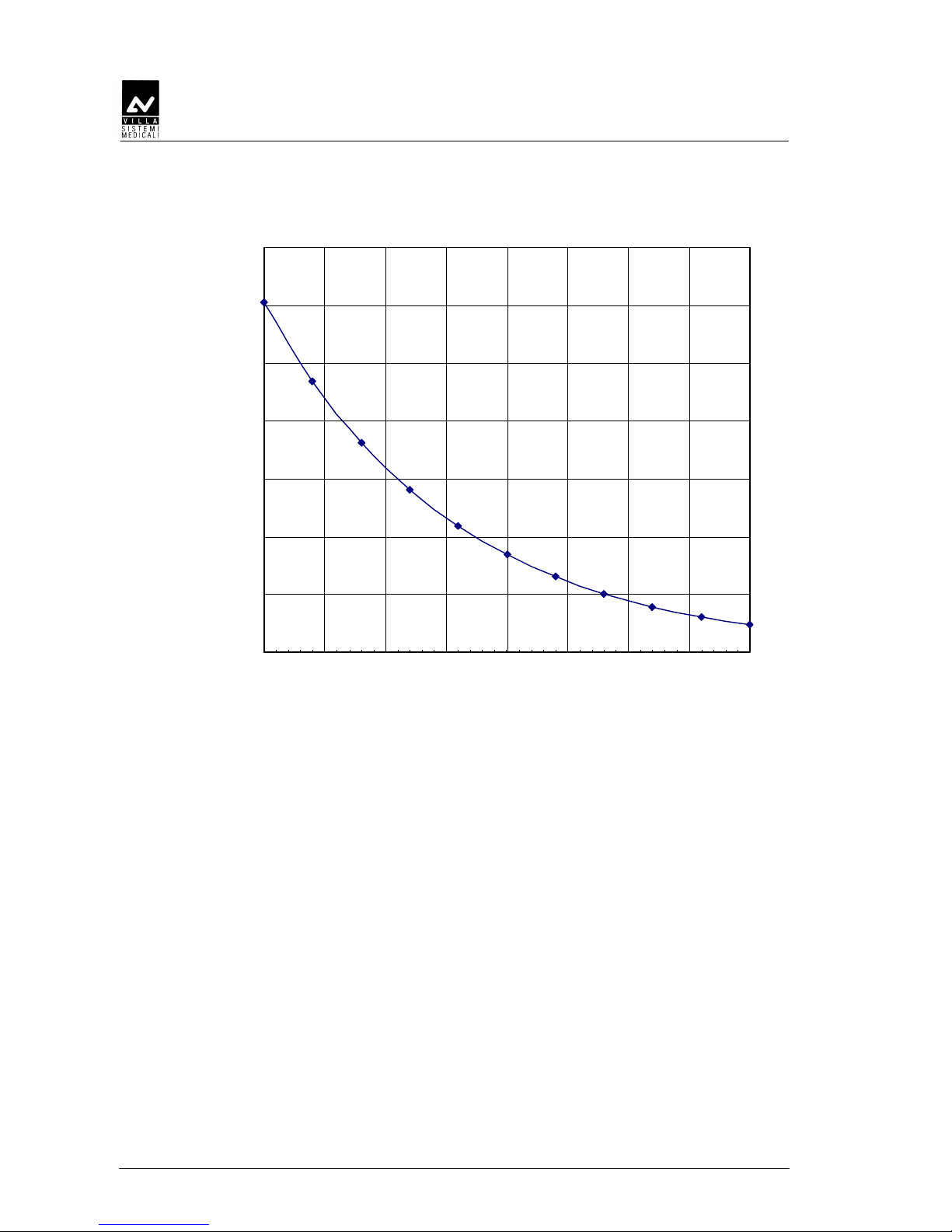
Cooling curve of tubehead
0
100
200
300
400
500
600
700
0 50 100 150 200 250 300 350 400
min
E(KJ)

SERVICE MANUAL
Technical features
(Rev. 5) ROTOGRAPH-D (120V)
4-7
4.3
4.34.3
4.3 Technical factors measuring method
Technical factors measuring methodTechnical factors measuring method
Technical factors measuring method
kVp The peak tube potential is directly measured with a non invasive
kVp-meter, accuracy ±3kVp. When performing the measurement, make
sure that measuring probe is completely covered by the X-ray beam.
A direct measurement of the high voltage can only be carried out by
specialized technicians in a suitable testing laboratory as it requires
disassembling of the tubehead.
mA The output current is determined by measuring the voltage drop on a
resistor (1kΩ, 5%) using a digital multimeter, connected to the
corresponding plugs, as indicated on paragraph 7.4 (digital multimeter
set to VDC 20V, 1V=1mA).
t The exposure times are determined by using a timer/counter, having an
accuracy of 0.1%, measuring the duration of part of the voltage applied
to the primary side of the tubehead, during the exposure phase.
SERVICE MANUAL
Technical features
ROTOGRAPH-D (120V) (Rev. 5)
4-8
4.4
4.44.4
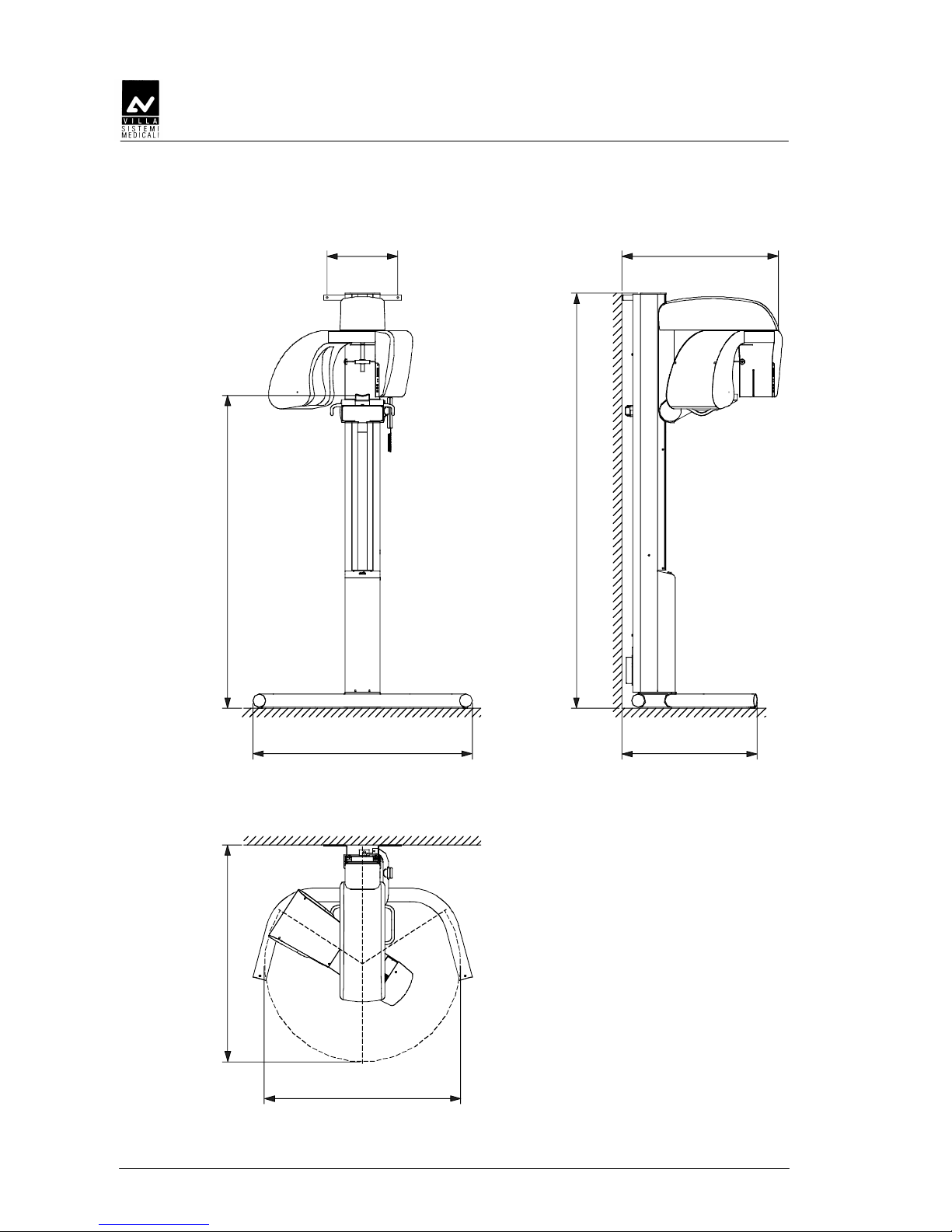
4.4 Overall dimension
Overall dimensionOverall dimension
Overall dimension
1240 (49")
1170 (46")
1256 (50")
957÷1791 (37.7"÷70.5")
774 (30.5")
2378 (93.6")
897 (35.3")406 (16")
Figure 4-1: ROTOGRAPH-D overall dimension

SERVICE MANUAL
Pre-installation
(Rev. 4) ROTOGRAPH-D (120V)
5-1
5.
5.5.
5. PRE
PREPRE
PRE----INSTALLATION
INSTALLATIONINSTALLATION
INSTALLATION
Please read carefully the information provided in this chapter in order to
ensure proper functioning of ROTOGRAPH-D.
The supplier is able to provide assistance and the necessary technical
advice necessary for the pre-installation phase; building works and the
pre-installation phase are to be charged to the customer and must be
made according to the information provided.
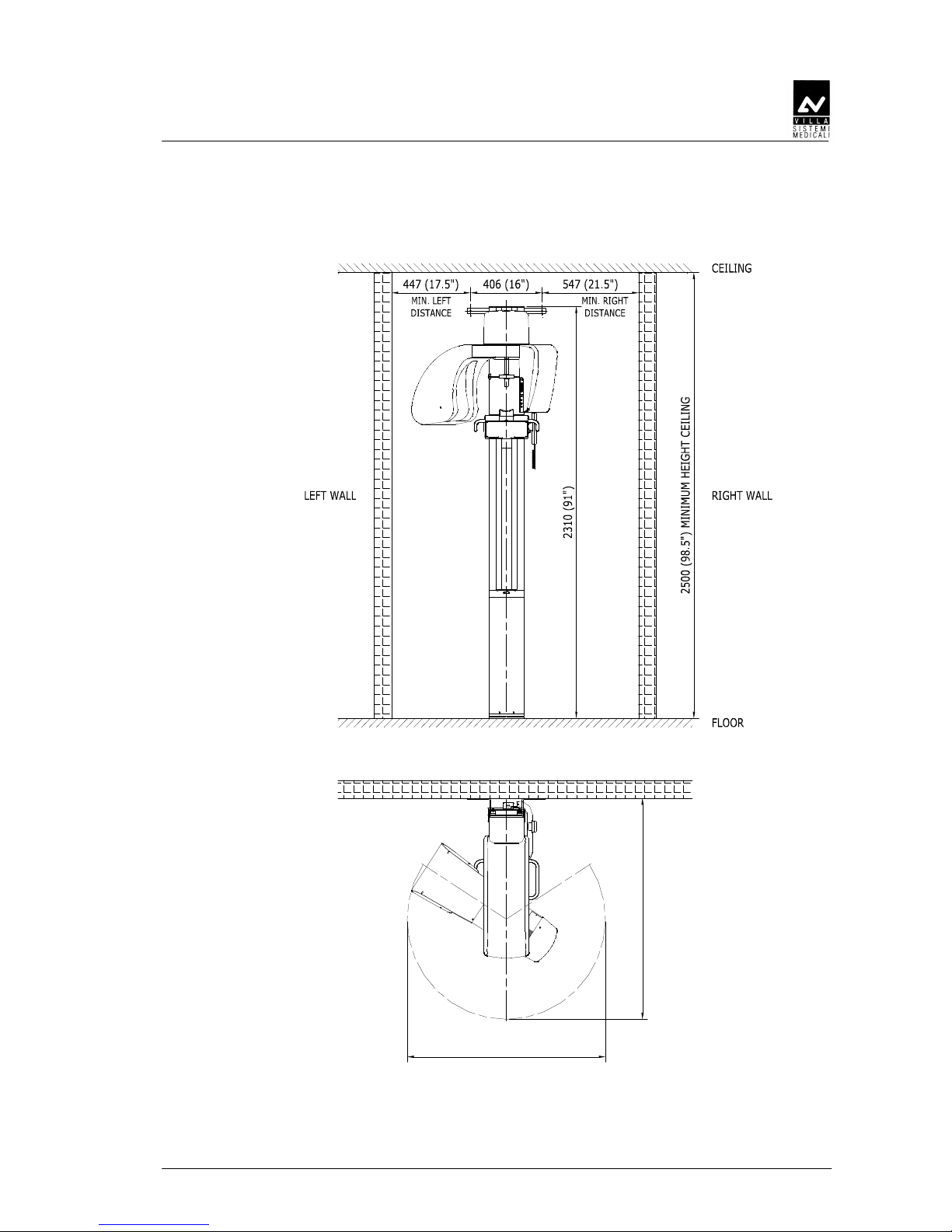
The room pre-installation requirements for a successful installation are:
• a minimum room ceiling height of 8 ft (2,5 mt) and an area to accept
ROTOGRAPH-D with its different configuration as showed in Figure
5-1.
• to transport the system into the room the doors must have a
minimum width of 36" (80cm).
SERVICE MANUAL
Pre-installation
ROTOGRAPH-D (120V) (Rev. 4)
5-2
5.1
5.15.1
5.1 Electrical requirements
Electrical requirementsElectrical requirements
Electrical requirements
• Supply single phase + ground 120V ± 10%
• Frequency 60 Hz
• Power input 1.1 kVA
• Max current 10A (at 108V)
• Apparent line resistance 0.5Ω max
NOTE:
The device is supplied as unit to be installed permanently
(EN60601-1 – paragraph 19).
Please DO NOT connect the unit to the line using a normal socket,
to avoid compromising the electrical safety.
WARNING:
The equipment must be connected to a breaker conforming with the
electrical standards in force in the country of installation.
It is mandatory to use a "Magnetothermal" breaker to separate the
appliance from the mains.
The equipment is provided with a connecting cable of the type SJT
AWG 16 (1,5mm²).
Grounding of this equipment must meet any standards in force.
NOTE:
The ROTOGRAPH-D IS PROVIDED with connections for remote control
and signalling device to be placed at the entrance of the X-ray room with
the following meanings:
• REMOTE EXPOSURE BUTTON: X-ray exposures can be
commanded by means of remote button to avoid operator presence
on the examination room. This push button must be "dead man"
type
• READY Light: (Green light 24V 40W max) signals the unit readiness
to make an X-ray exposure
• X-RAY Light: (Yellow light 24V 40W max) signals "a no entrance
condition" due to radiation emission.
In order to connect these devices, a 5 wire conductors cable of
0,5mm² (AWG 18) must be prepared prior to the complete installation.
SERVICE MANUAL
Pre-installation
(Rev. 4) ROTOGRAPH-D (120V)
5-3
WARNING:
21 CFR requires that indication of the technique factors be visible from
the operator’s position. In case of use of the remote button the
Manufacturer expressly by this warning, disclaims any responsibility, as
to compliance to Federal Regulations. It is responsibility of the installers
to observe and abide by the rules.
NOTE:
The electrical connection has to be made on the X15 terminal (refer to
Figure 6-8 and the general wiring diagram at chapter 9).

SERVICE MANUAL
Pre-installation
ROTOGRAPH-D (120V) (Rev. 4)
5-4
5.2
5.25.2
5.2 Environmental condition
Environmental conditionEnvironmental condition
Environmental condition
The performance of the equipment are assured if the room environment
must be treated in such a way as to ensure a relative humidity between
50% and 75 % and a temperature between +50°F ÷ +104°F (+10° ÷ +40°).
WARNING:
Proper backing is absolutely essential for all wall mounted versions. The
wall bracket supplied must be attached to the wall bearing in mind that
the wall backing has a capacity to sustain a load of 2000N (about
200kg - 441 lbs) per bolt applied. Backing and proper support is the full
responsibility of the owner.
5.3
5.35.3
5.3 Unpacking
UnpackingUnpacking
Unpacking
ROTOGRAPH-D is shipped packed in two cartons.
Dimensions, net weight, gross weight and the packing contents are listed
in the following table:
Weight
Packing dimension Contents
Net Gross
100x95x100 cm
(40x37½x40 inches)
WxTxH
- Motor group
- Tubehead
- Counterweights
- Accessories
210 kg
(462 lbs)
235 kg
(517 lbs)
250x25x18 cm
(98½x9¾x7 inches)
WxTxH
- Column
40 kg
(88 lbs)
45 kg
(99 lbs)
SERVICE MANUAL
Pre-installation
(Rev. 4) ROTOGRAPH-D (120V)
5-5
5.4
5.45.4
5.4 Space re
Space reSpace re
Space requirements
quirementsquirements
quirements
1240 (45")
1170 (46")
Figure 5-1

SERVICE MANUAL
Pre-installation
ROTOGRAPH-D (120V) (Rev. 4)
5-6
THIS PAGE IS INTENTIONALLY LEFT BLANK
SERVICE MANUAL
Installation
(Rev. 4) ROTOGRAPH-D (120V)
6-1
6.
6.6.
6. INSTALLATION
INSTALLATIONINSTALLATION
INSTALLATION
NOTE:
ROTOGRAPH-D is dispatched preassembled in groups.
The mechanical assembly consists exclusively in assembling these
groups together.
Calibration of the ball bearing, brakes and eventual tightening torques is
factory preset before delivery; any intervention on these parts, besides
not being necessary, can cause malfunction.
Depending on the configuration of the unit, the following fixing methods
must be used:
Fix legs to floor Use wall bracket Fix column to floor
Version with legs
•
Version without legs
• •
 Loading...