

Villager Esprit, ESPRIT BK077 Operating & Installation Manual
PLEASE RETAIN THIS GUIDE FOR FUTURE REFERENCE
Operating & Installation Manual
Rev 06
August 2010
Part No. AFS1399
Esprit
BK077
EN 13240:2004+
Amd. A2:2004
10

Congratulations on your choice of a Villager stove.
More than 40 years experience has been put into the
development of our Villager Esprit stove to ensure
ultimate performance and years of trouble free use
and enjoyment.
Every detail of the stove has been carefully designed and
engineered which is why we are so confident in the
reliability of our products.
Should you have any questions about our Villager Esprit
stove, that are not covered by this manual, please contact
the Villager retailer in your area, or call our technical support
department on 0844 847 5107.
Copyright 2010 Arada Ltd
This booklet has copyright and may not be copied in whole, or part, or used for any
purpose other than that for which it is supplied without express written consent from Arada Ltd
Villager Esprit Stove 2
PLEASE NOTE— Arada has a policy of continuous product development and therefore we
reserve the right to amend the specification without prior notice.
Due to printing cycles, items or options may be described before they are generally available
or after they have ceased, so please check with your retailer or dealer.
All Villager Esprit stoves are approved to European
Standard EN 13240 and CE marked.*
These appliances listed within this manual have been
approved by HETAS Ltd as an intermittent operating
appliance for burning wood only.*
*NOTE : Only applicable to Esprit 8 model.

Contents
Villager Esprit Stove
Page No.
INTRODUCTION
Warning Notice 4
Safety Notices 5
The Principle Of The Stove 5
Check List 6-7
Data Plate Information 7
Technical data 8
INSTALLATION
General Precautions 9
Asbestos 9
Handling 9
Hearth 9
Combustible Materials 9
Air For Combustion 9
Roping Guide For Flue Outlet & Hot Plate 10
Fitting The Flue Outlet & Hotplate 10
Sealing The Terminals 10
Flues & Chimneys 11-14
Firebox Liner Panels 15-16
Adjusting The Self Levelling Feet 17
Final Check 17
Building Control Consent Checklist 18
Page No.
SERVICE & MAINTENANCE
Annual Maintenance 19
Cleaning 19
Chimney Sweeping 19
Door Glass 19
Outer Finish 19
Summer Storage / Non Usage 20
Adjusting The Main Door 20
Fuel Retaining - inspection 20
Main Fire Door Rope Replacement 21
Fire Door Glass Replacement 21-22
Primary Air Inlet 21
Service Record 23
OPERATING INSTRUCTION
Lighting The Fire 24
Burning Wood 25
Reduced Burning 25
Extended Burning 26
Safety Warning 26
Over Firing & Chimney Fires 26
Ash Removal 26
Air Inlet Controls (Primary/Air wash) 27
Multi Purpose Operating Tool 28
(Empty The Ash Pan/ Air Wash /
Primary Control Knob)
Main Fire Door Handle 29
OPTIONAL EXTRA/ACCESSORIES 30
SPARE PARTS LIST 31-33
GUARANTEE 34-35
FACTORY CHECK LIST 36
3

WARNING
IT IS A LEGAL REQUIREMENT THAT THE INSTALLATION OF ALL
NEW OR REPLACEMENT, WOOD OR SOLIDFUEL HEATING
APPLIANCES ARE REQUIRED TO OBTAIN BUILDING CONTROL
APPROVAL FROM YOUR LOCAL AUTHORITY OR THE
INSTALLATION WORK MUST BE CARRIED OUT THROUGH A
GOVERNMENT APPROVED COMPETENT PERSONS SCHEME
SUCH AS OPERATED BY HETAS.
IF IN DOUBT, CONTACT HETAS LIMITED
TELEPHONE NUMBER : 0845 634 5626
www.hetas.co.uk
THIS STOVE MUST NOT BE CONNECTED
TO A SHARED FLUE SYSTEM
TO ALL USERS
PETROLEUM COKE
SOME OF WHOSE BRAND NAMES ARE
„CALCO’, ‘PETROCOKE’ AND ‘WONDERCO’
MUST NOT BE BURNED IN THIS APPLIANCE
BITUMINOUS HOUSE COAL
SHOULD NEVER BE USED IN YOUR STOVE
TO USE THESE FUELS WILL INVALIDATE
THE APPLIANCE GUARANTEE.
IF IN DOUBT CONTACT THE SOLID FUEL ASSOCIATION
TELEPHONE NUMBER 0845 601 4406
www.solidfuel.co.uk
4 Villager Esprit Stove

SAFETY
A fireguard conforming to BS 8423:2002
should be used in the presence of children
and old or infirm people.
Please note, this appliance should be used
with the fire door closed at all times except
when re-fuelling or de-ashing.
Do not use aerosol sprays or any other
flammable materials near the appliance
under fire.
Do not fit an extractor fan in the same
room as the appliance.
Fire cement is caustic, hand and eye
protection should always be worn,
prolonged contact with the skin should be
avoided.
Arada Ltd will not be responsible for any
consequential or incidental loss or
injury however caused.
Before continuing any further, with the
installation of this appliance please read the
following guide to manual handling.
Always obtain assistance when lifting the
appliance
When lifting always keep your back straight,
bend your legs not your back
Avoid twisting at the waist. It is better to
reposition your feet.
Avoid upper body / top heavy bending. Do
not lean forwards or sideways when
handling the fire
Always grip with the palms of your hands
do not use your fingertips for support
Always keep the stove as close to the body
as possible as this will minimise the
cantilever action.
Use gloves to provide additional grip.
THE PRINCIPLE OF THE STOVE
Your Villager stove is built to the highest
standard of craftsmanship using the best
materials and the most modern equipment
available. It is a highly efficient and sophisticated
piece of machinery and when properly installed
and operated it should provide a lifetime of
heating satisfaction.
Safety is the most important consideration when
installing your fire. If not properly installed and
operated a house fire may result. Installation
must comply with the Building Regulations and
conform to all safety standards.
Villager produce a variety of appliances ranging
in physical size and heat output all with
traditional style features and appearance.
The fire door is fitted with a special high
temperature ceramic glass panel through which
the fire can be viewed.
The stove is lined with firebricks or heat
reflective panels which ensure complete
combustion and provide a good heat store to
even out fluctuations in burning.
An internal throat plate produces turbulence to
encourage secondary combustion and direct the
flue gas around the whole upper firebox before
allowing it to escape up the chimney.
Most, Villager stoves are fitted with an „air wash‟
so called because it provides a curtain of high
speed preheated air behind the glass to help
keep it clean and provide secondary air / over
draught.
The provision of two inlets on all stoves gives a
wide range of primary / secondary air, under
draught / over draught combinations. The
optimum setting will only be established by
experience in firing the appliance, and will
depend on the fuel, the position of the appliance
in the house, and conditions of the chimney etc.
Villager Esprit Stove
INTRODUCTION
5

CHECK LIST
6
Inside the appliance body you should find the following:
Part Description & Visual Aid (not to scale)
Esprit
4kw
Esprit
6kw
Esprit
8kw
Esprit
10kw
1. Fuel Retainer
1 1 1 1
2. Wood Burning Tray
1 1 1 1
3. Standard style Throat Plate
1 0 1 0
4. EGD style Throat Plate
0 1 0 1
5. Flue Spigot
1, ( 4" ) 1, ( 5" ) 1, ( 5" ) 1, ( 5" )
6. Hot Plate
1, ( 4" ) 1, ( 5" ) 1, ( 5" ) 1, ( 5" )
7. Ash Pan
1 1 1 1
8. Operating Tool
1 1 1 1
9. Instruction Manual
1 1 1 1
Villager Esprit Stove
CHECK LIST
Inside the appliance you should find the following :
Villager Esprit Stove 7
Description & Visual Aid (not to scale)
Esprit
4kw
Esprit
6kw
Esprit
10kw
Esprit
8kw
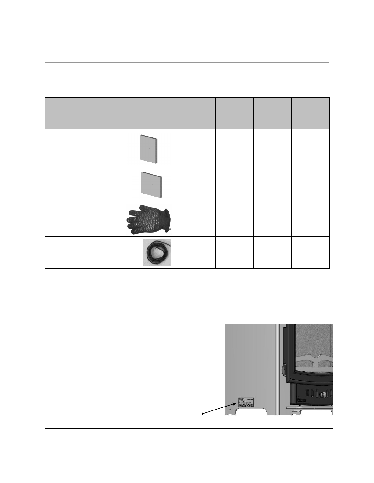
9. Side Liners 2 2 2 2
10. Rear Liners 1 1 2 2
11. Stove Glove 1 1 1 1
12. Self Adhesive Sealing Rope
(High Temperature) 1.3 Mtrs
1 1 1 1
Data Plate Information
Please Note- The Esprit stove is fitted with a data plate located
at the left hand side, towards the rear of the stove. The plate
contains important information and must be observed when
installing the stove.
Data Plate
Location
8
TECHNICAL DATA
Villager Esprit Stove
TECHNICAL DATA
Esprit Wood
4kw
Esprit Wood
6kw
Esprit Wood
8kw
Esprit Wood
10kw
Nominal Heat Output (Kw) 4 6 8 10
Efficiency Nett (%) 77.7* 72.1* 80.4 75.8*
Mean Flue Gas Temperature (°C) 263* 307* 290 335*
Mean CO Emission @ 13% O2 (%) 0.61* 0.47* 0.52 0.44*
Flue Mass Gas Flow (g/s) NA NA 5.2 NA
Minimum Distance to Combustible
materials (mm)
NA NA
Side = 700
Rear = 850
NA
Height (mm) 508 520 560 575
Width (mm) Across Canopy 484 540 608 695
Depth (mm) (Inc. Handle) 363 368 355 372
Height To Centre Of Rear Flue (mm) 414 414 449 464
Depth From Back To Flue Centre (mm) 98 112 110 110
Flue Diameter (mm) 102(4”) 127(5”) 127 (5”) 127 (5”)
Weight Packed (Kg) 66.5 77 87 133
Weight Nett (Kg) 62.5 73 82 128
Ideal Log Length (mm) 325 350 400 475
Note: Figures shown with an asterix are in house testing results.

GENERAL PRECAUTIONS
Note : All local regulations, including those
referring to National and European standards need
to be complied with, when installing the appliance.
The Building Regulations for England and Wales
2000 ref Approved Document J 2002 edition
(issued by the DTLR).
The Building Standards (Scotland) (Consolidation)
Regulations.
Detailed recommendations for installation of
appliances, chimneys and flues are outlined in the
current issue of the following British Standards :
BS6461, BS8303 & BS4543.
Any Manufacturer’s Instructions must not
be taken as overriding statutory
requirements.
Before any installation work is undertaken
consideration must be given to the Health
and Safety at Work Act 1974. Safe working
practices should be followed at all times.
During installation ensure that adequate
precautions are taken to avoid unnecessary risk to
yourself or any householder. In particular the
danger from caustic nature of the fire cement
should be avoided by using these accepted
methods :
Wear gloves when handling fire cement
Wear goggles when chiselling or looking up
chimneys.
Make sure that Building Regulations are adhered
to during installation along with any local by-laws.
In the case of heating systems make sure that the
pipe work is correctly bonded to ensure electrical
earth continuity.
ASBESTOS
All Villager stoves contain no asbestos in their
manufacture or construction. If there is a possibility
of disturbing any asbestos in the course of
installation, then please seek specialist guidance
and use appropriate protective equipment.
HANDLING
The safe handling guidelines are set out on page 5
of this manual, to make movement easier, internal
fittings, fuel retainers, grates, firebox liners, flue
outlets, hot plates, throat plates etc, can be
removed. Care should be taken to make sure that
the hinges are not damaged during installation.
HEARTH
The stove shall be installed on a floor with
adequate load bearing capacity. If the existing
construction does not meet this prerequisite,
suitable measures (e.g.: load distributing plate)
should be taken to achieve it.
Ideally, the appliance should stand on a
constructional hearth of non-combustible
materials not less than 125mm (5”) thick
conforming to Building Regulations.
Dimensions of the hearth should project at least
300mm (12”) forward of the front of the appliance
and 150mm (6”) at the sides.
The surface of the hearth should be free of
combustible materials. In most buildings with solid
concrete or stone floors, the requirement will be
met by the floor itself, but mark the hearth to
ensure floor coverings are kept well away or use
different levels to mark the hearth perimeter.
COMBUSTIBLE MATERIALS
Please view the technical data (see page 8) and
observe the minimum distance to combustible
materials, which is applicable to your stove model.
Ideally, adjacent walls should be of suitable non
combustible construction, preferably brickwork. In
large fireplaces take care that any supporting
beam is protected by a 13mm (0.5”) sheet of
Masterboard or Superlux spaced 13mm (0.5”) off
the surface with strips of non combustible material.
Make sure that there is a gap between an
un-insulated flue system and any combustible
material. This gap must be at least 3X the outside
diameter of the flue pipe, or 1.5X the flue diameter
to non combustible surfaces. See illustration on
page 13.
AIR FOR COMBUSTION
There must always be a permanent means of
providing air for combustion into the room in which
the stove is installed. A permanent vent with a total
free area of at least 550mm2 for every KW rated
above 5KW should be connected directly to the
outside air or to an adjacent room which itself has
a permanent vent of the same size direct to the
outside air. The positioning of any air vent must be
so, that it cannot be liable to blockage or
obstruction. Please note : The fitting of an
extractor fan to either of these rooms is not
permitted.
Villager Esprit Stove 9
INSTALLATION
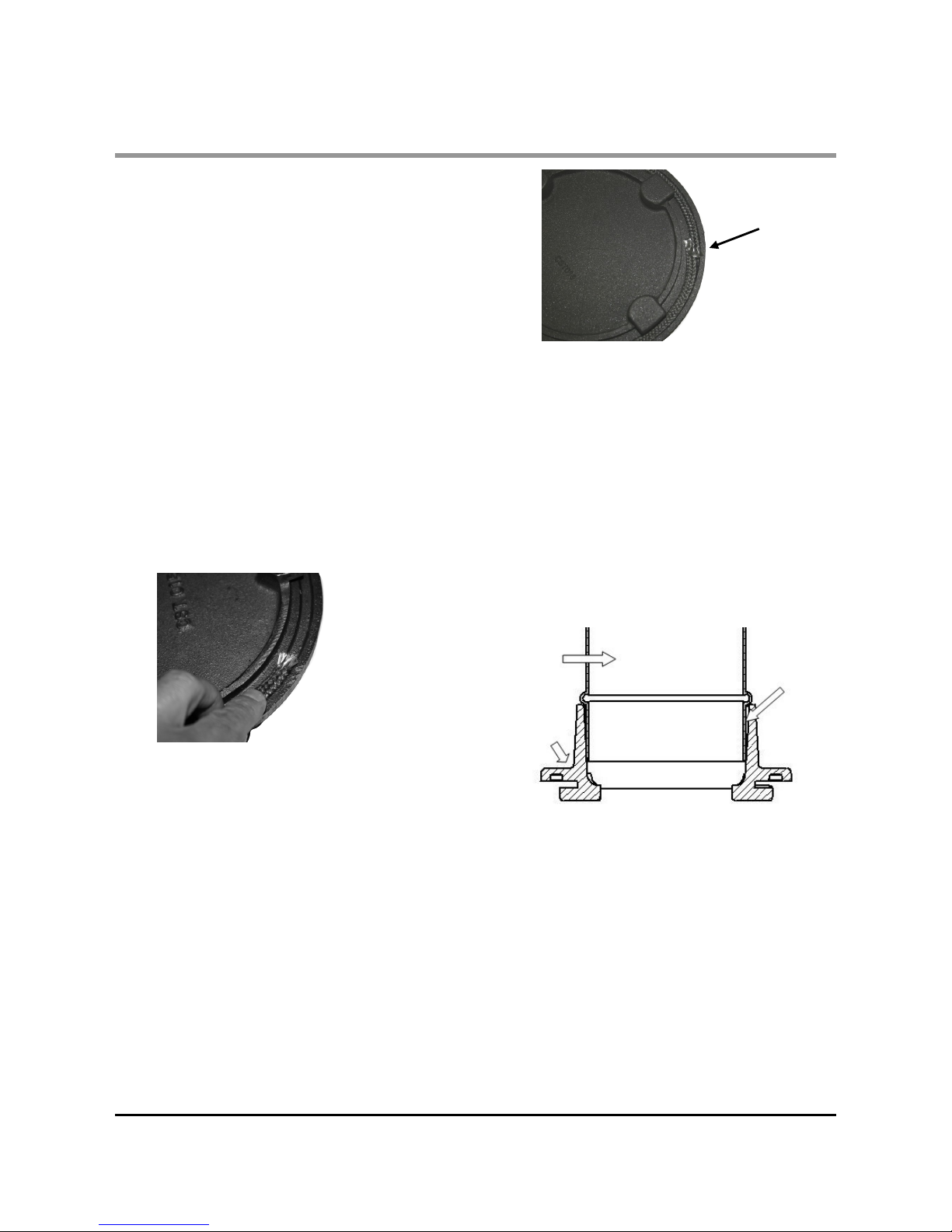
ROPING GUIDE FOR FLUE
OUTLET AND HOT PLATE
All Villager hot plates and spigots are
manufactured with a rope groove to accept our
high temperature self adhesive sealing rope
supplied.
This eliminates the need for messy and caustic fire
cement, and allows for easy removal for inspection
and cleaning, without the accompanying re-sealing
mess associated with fire cement.
To seal the hot plate and spigot proceed as
follows:
1)The self adhesive sealing rope for the hot plate
and spigot is supplied in a single length of
1300mm and needs to be cut in half to begin with.
2) Each length of approximately 650mm should be
fitted into the groove on the mating face of the hot
plate or spigot. See Fig. 1.
3) Start by removing a small section of the
adhesive backing paper (approx. 25mm) and
remove the remaining backing paper as you
proceeded.
4) Begin at the rope overlap point, mid way between the securing lugs and work your way around
the groove making sure the rope is pressed accurately and firmly into the groove. Finish the rope
approximately 10mm past the start point.
5) If the rope is allowed to ride up the side of the
receiving groove, rather than sitting squarely, in
the middle, it will impede the fitting of the hot
plate / spigot and may lead to leaks. See Fig. 2.
6) Finally press round the sealing rope with a steel
rule or similar device, to ensure adhesion is even.
Repeat for the remaining casting.
Villager Esprit Stove 10
INSTALLATION
Fig. 1. Apply Rope To Groove
Inside
Flue
Pipe
Outer
Spigot
FITTING THE FLUE OUTLET AND
HOT PLATE
Take the flue spigot and lock into place by
rotating anti-clockwise and tighten by tapping with
a block of wood and mallet from inside of the
appliance. Similarly, fit the hot plate (blanking
plate) to the unused opening.
Place appliance on the hearth and make sure that
it is level and does not rock.
Connect the chimney ensuring all joints are sealed
with fire cement.
Note : The flue pipe must be fitted inside the outlet
spigot. Failure to do so could result in the spillage
of condensation running down the flue.
SEALING OF TERMINALS
If an add in boiler is not to be fitted, please
ensure that the two partially cut circular terminals
(located on the rear of the appliance) are sealed
with fire cement, and thus preventing surplus air
entering the firebox, resulting in less efficiency
and poor fuel consumption.
Fig. 2. Correct Roped Hot Plate
Joint
Overlap
Fig. 3. Flue & Spigot Fitting

FLUES AND CHIMNEYS
The flue draw is critical on any installation and
should be checked to ensure that it matches what
is specified. If it is higher than recommended,
provision must be made to correct the over draw.
The draw can vary in different weather conditions
and the customer should be made aware of this.
Failure to correct an over-drawing flue will
invalidate the warranty.
Please remember that chimney draught is
dependent on four main factors :
Flue gas temperature
Flue height
Flue size
Flue terminal
The stove must be connected to a suitable and
efficient flue that products of combustion (fumes)
from the stove are expelled to the outside air. To
ensure a good up draught it is important that the
flue gases are kept warm and that the flue size
suits the stove. The termination of the outlet at the
top of the flue also needs to comply with Building
Regulations. The minimum effective height of the
flue must be at least 4.5 metres from the top of the
stove to the top of the flue outlet. When warm the
flue draught should be between 0.1 to 0.2 mb.
A chimney may comply with regulations but still be
subject to down draught and similar problems. A
chimney terminating above the ridge level is
generally less likely to suffer such problems.
If a new chimney is being provided it should fully
comply with the relevant Building Regulations that
specify the requirements for solid fuel burning
installations. Suitable types of chimney include the
following :
Masonry Chimney : Built with clay or concrete
liners, or a chimney block system meeting Building
Regulations. These types of chimney should be
installed in accordance with the Building
Regulations and BS 6461:Part 1.
Factory Made Insulated Chimney : Complying
with BS 4543:Part 2 (often called “Class 1
prefabricated metal chimney”). These types of
chimney should be installed in accordance with
Building Regulations and BS 7566: Parts 1 to 4.
Villager Esprit Stove 11
INSTALLATION
Due to the gradual introduction of Europe Chimney
Standards chimneys will be specified according to
their performance designation as defined in BS EN
1443 that covers the General Requirements for
chimneys. The minimum performance designation
required for use with solid fuel burning stoves is
T450 N2 S D3.
The flue and chimney installation must be carefully
checked by a competent person before fitting the
stove to ensure it is suitable and will work safely.
If the chimney is old (ie: built of brick or stone
without a liner) or being opened up for reuse
additional checks and smoke testing a described in
Appendix E of the Approved Document J 2002
Edition should also be carried out to ensure the
flue and chimney are good operating condition.
If the flue size is more than 225mm (9”) diameter
or 200mm (8”) X 200mm (8”) square, a suitable
lining of 150mm (6”) diameter should be fitted, or if
the flue length is over 5.5 metres one size larger
than the appliance outlet should be fitted. This
should be a double skin stainless steel flexible liner
that is independently certified for use with solid
fuel. Details of suitable linings for use with wood &
solid fuel are given in the Official HETAS guide
that can be viewed on their website at
www.hetas.co.uk.
It is also important that suitable flue pipe complying
with the Building Regulations is used to connect
the stove to the flue in the chimney and that suitable access is provided into the flue for regular
inspection and sweeping of the flue ways.
The installer should comply with Building Regulations requirements in respect of providing a Notice
Plate giving details on the chimney, flue lining,
hearth and fireplace installation. Approved Document J of the Building Regulations for England &
Wales is available from The Stationary Bookshops
and can also be viewed at the ODPM website at
www.safety.odpm.gov.uk/bregs/brads.htm.
Details on the relevant Building Regulations and
BS British Standards are given in the “ General
Precautions” section of these instructions.
Chimneys should be as straight as possible.
Horizontal runs should be avoided except where
 Loading...