

Village QV32B, QV36B Installer's Manual
Models:
QV32B
QV36B
READ THIS MANUAL BEFORE INSTALLING OR
OPERA TING THIS APPLIANCE. THIS INSTALLERS
GUIDE MUST BE LEFT WITH APPLIANCE FOR
FUTURE REFERENCE.
WARNING: IF THE INFORMATION
IN THESE INSTRUCTIONS IS NOT
FOLLOWED EXACTL Y, A FIRE OR
EXPLOSION MAY RESULT CAUSING PROPERTY DAMAGE, PERSONAL INJUR Y, OR DEA TH.
Installers Guide
Underwriters
Laboratories Listed
WARNING: IMPROPER INSTALLATION, ADJUSTMENT, ALTERATION,
SERVICE OR MAINTENANCE CAN
CAUSE INJURY OR PROPERTY DAMAGE. REFER TO THIS MANUAL. FOR
ASSIST ANCE OR ADDITIONAL INFORMATION CONSULT A QUALIFIED INST ALLER, SERVICE AGENCY , OR THE
GAS SUPPLIER.
- Do not store or use gasoline or other flammable vapors and liquids in the vicinity of this
or any other appliance.
- What to do if you smell gas
• Do not try to light any appliance.
• Do not touch any electrical switch.
• Do not use any phone in your building.
• Immediately call your gas supplier from a
neighbor's phone. Follow the gas supplier's
instructions.
• If you cannot reach your gas supplier, call
the fire department.
- Installation and service must be performed by a
qualified installer, service agency, or the gas
supplier.
Quadra-Fire, a brand of Hearth & Home Technologies
1445 North Highway, Colville, WA 99114
Printed in U.S.A. Copyright 2006
This product may be covered by one or more of the following patents: (United States) 4593510, 4686807, 4766876, 4793322, 481 1534, 5000162, 5016609, 5076254, 51 13843, 5191877, 5218953, 5263471,
5328356, 5341794, 5347983, 5429495, 5452708, 5542407, 5601073, 5613487, 5647340, 5688568, 5762062, 5775408, 5890485, 5931661, 5941237, 5947112, 5996575, 6006743, 6019099, 6048195, 6053165,
6145502, 6170481, 6237588, 6296474, 6374822, 6413079, 6439226, 6484712, 6543698, 6550687, 6601579, 6672860, 6688302B2, 6715724B2, 6729551, 6736133, 6748940, 6748942, 6769426, 6774802,
6796302, 6840261, 6848441, 6863064, 6866205, 6869278, 6875012, 6880275, 6908039, 6919884, D320652, D445174, D462436; (Canada) 1297749, 2195264, 2225408, 2313972; (Australia) 780250,
780403, 1418504 or other U.S. and foreign patents pending.
In the Commonwealth of Massachusetts:
• installation must be performed by a licensed
plumber or gas fitter;
See T able of Content s for location of additional
Commonwealth of Massachusetts requirements.
1.This appliance may be installed in an aftermarket, permanently located, manufactured (mobile) home, where not prohibited
by local codes.
2. This appliance is only for use with the type
of gas indicated on the rating plate. This
appliance is not convertible for use with
other gases, unless a certified kit is used.
Please contact your Quadra-Fire dealer
with any questions or concerns. For the
number of your nearest Quadra-Fire
dealer, please visit www .quadrafire.com.
1Quadra-fire • QV32B, QV36B • 2013-900 Rev. F • 9/06
SAFETY AND WARNING INFORMATION
READ and UNDERSTAND all instructions carefully
!
before starting the installation. FAILURE TO
FOLLOW these installation instructions may result
in a possible fire hazard and will void the warranty.
Prior to the first firing of the fireplace, READ the
!
Using Your Fireplace section of the Owners Guide.
DO NOT USE this appliance if any part has been
!
under water. Immediately CALL a qualified service
technician to inspect the unit and to replace any part
of the control system and any gas control which has
been under water.
THIS UNIT IS NOT FOR USE WITH SOLID FUEL.
!
Installation and repair should be PERFORMED by a
qualified service person. The appliance and venting
!
system should be INSPECTED before initial use
and at least annually by a professional service
person. More frequent cleaning may be required
due to excessive lint from carpeting, bedding
material, etc. It is IMPERATIVE that the unit’s
control compartment, burners, and circulating air
passageways BE KEPT CLEAN
adequate combustion and ventilation air.
to provide for
These units MUST use one of the vent systems
described in the Installing the Fireplace section of the
!
Installers Guide. NO OTHER vent systems or
components MAY BE USED.
This gas fireplace and vent assembly MUST be
!
vented directly to the outside and MUST NEVER be
attached to a chimney serving a separate solid fuel
burning appliance. Each gas appliance MUST USE
a separate vent system. Common vent systems are
PROHIBITED.
INSPECT the external vent cap on a regular basis to
!
make sure that no debris is interfering with the air
flow.
The glass door assembly MUST be in place and
!
sealed, and the trim door assembly MUST be in
place on the fireplace before the unit can be placed
into safe operation.
DO NOT OPERATE this appliance with the glass
!
door removed, cracked, or broken. Replacement of
the glass door should be performed by a licensed or
qualified service person. DO NOT strike or slam the
glass door.
Always KEEP the appliance clear and free from
!
combustible materials, gasoline, and other
flammable vapors and liquids.
NEVER OBSTRUCT the flow of combustion and
!
ventilation air. Keep the front of the appliance
CLEAR of all obstacles and materials for servicing
and proper operations.
Due to the high temperature, the appliance should
be LOCATED out of traffic areas and away from
!
furniture and draperies. Clothing or flammable
material SHOULD NOT BE PLACED on or near the
appliance.
Children and adults should be ALERTED to the
!
hazards of high surface temperature and should
STAY AWAY to avoid burns or clothing ignition.
Y oung children should be CAREFULL Y SUPERVISED
when they are in the same room as the appliance.
The glass door assembly SHALL ONLY be replaced
!
as a complete unit, as supplied by the gas fireplace
manufacturer. NO SUBSTITUTE material may be
used.
DO NOT USE abrasive cleaners on the glass door
!
assembly. DO NOT ATTEMPT to clean the glass
door when it is hot.
Turn off the gas before servicing this appliance. It is
recommended that a qualified service technician
!
perform an appliance check-up at the beginning of
each heating season.
Any safety screen or guard removed for servicing
!
must be replaced before operating this appliance.
DO NOT place furniture or any other combustible
!
household objects within 36 inches of the fireplace
front.
2 Quadra-fire • QV32B, QV36B • 2013-900 Rev. F • 9/06

TABLE OF CONTENTS
Safety and Warning Information ......................................................... 2
Service Parts Lists................................................................................. 4
Î
Section 1: Approvals and Codes.......................................................... 9
Appliance Certification ............................................................................. 9
Installation Codes .................................................................................... 9
High Altitude Installations ........................................................................ 9
Requirements for the Commonwealth of Massachusetts........................ 10
Î
Section 2: Getting Started .................................................................. 11
Introducing the Village Collection Gas Fireplaces .................................. 1 1
Pre-installation Preparation.................................................................... 11
Section 3: Installing the Fireplace..................................................... 14
Constructing the Fireplace Chase .......................................................... 14
Step 1 Locating the Fireplace........................................................... 14
Step 2 Framing the Fireplace ........................................................... 15
Step 3 Installing the V ent System.................................................... 18
A. Vent System Approvals ................................................... 18
B. Installing V ent Components............................................. 28
C. Vent Termination.............................................................. 31
Step 4 Positioning, Leveling, and
Securing the Fireplace .......................................................... 34
Step 5 The Gas Control Systems..................................................... 34
Step 6 The Gas Supply Line............................................................. 35
Step 7 Gas Pressure Requirements................................................. 35
Step 8 Wiring the Fireplace .............................................................. 3 6
Î
Step 9 Finishing ............................................................................... 37
Step 10 Installing Trim, Logs, and Ember Material ............................. 3 7
Installing the Trim.................................................................. 37
Positioning the Logs ............................................................. 38
Shutter Setting...................................................................... 38
Placing the Ember Material................................................... 38
Glass Specifications ............................................................. 38
Step 1 1 Lighting the Appliance ........................................................... 39
Step 12 Before Lighting the Fireplace................................................. 40
Step 13 Lighting the Fireplace............................................................ 40
After the Installation ............................................................................... 40
Section 4: Maintaining and Servicing Your Fireplace .................... 41
Section 5: Troubleshooting ............................................................... 42
Limited Lifetime Warranty ................................................................. 44
Î
= Contains updated information.
3Quadra-fire • QV32B, QV36B • 2013-900 Rev. F • 9/06
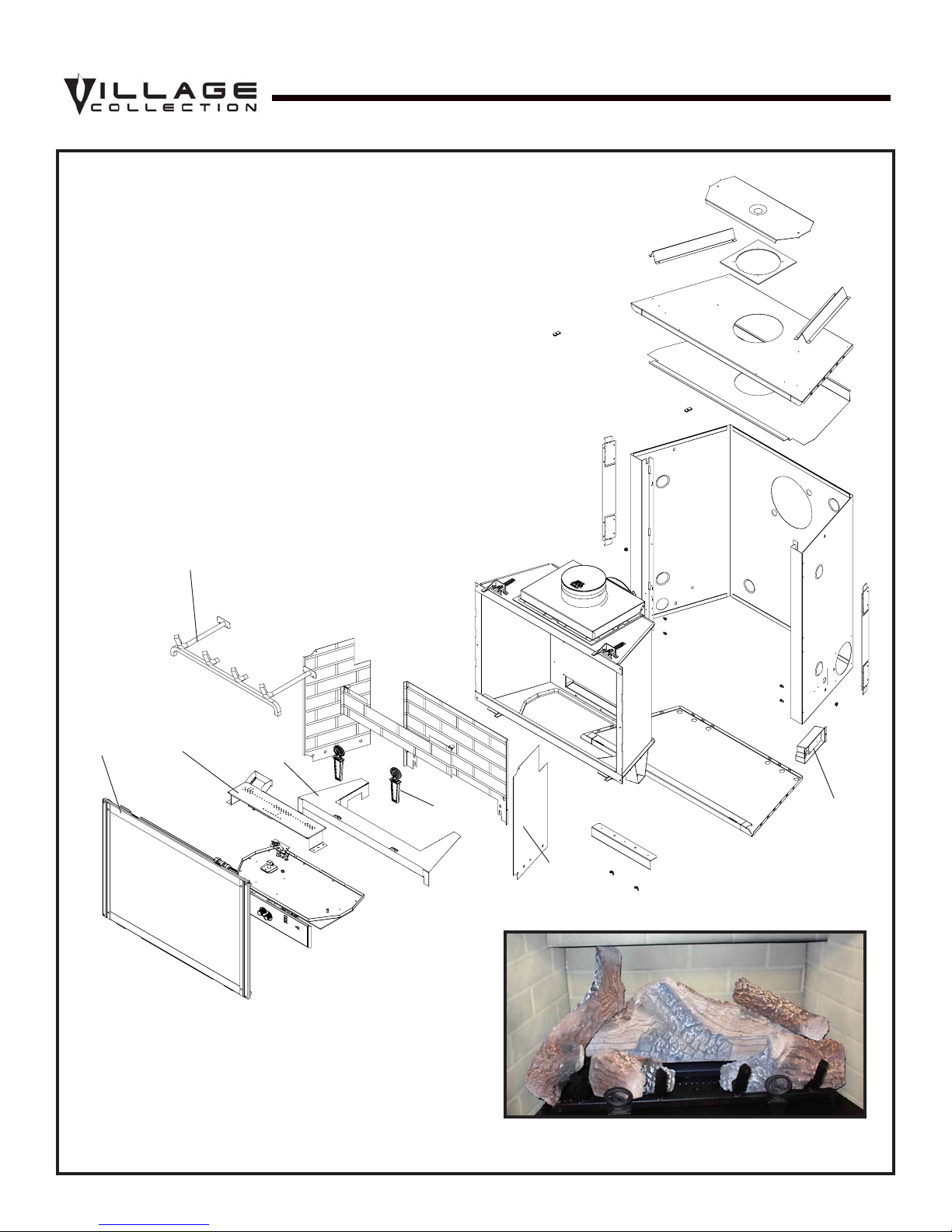
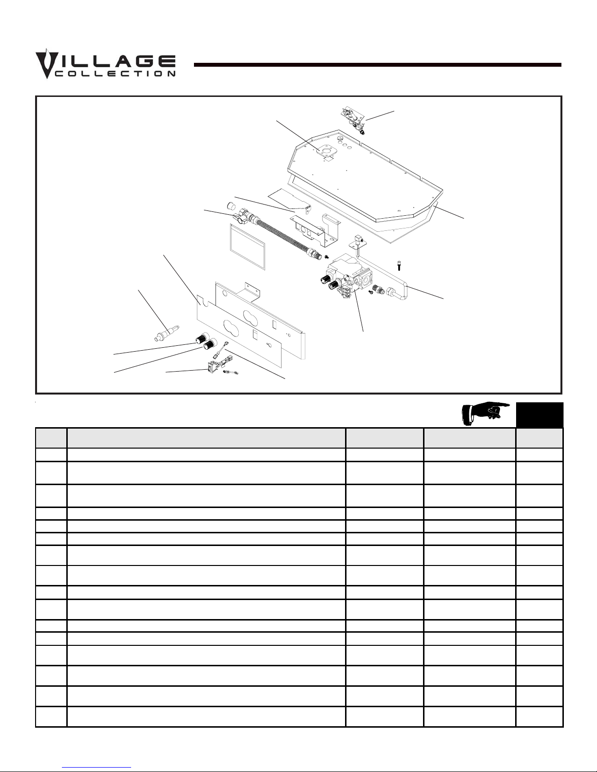
Service Parts
QV32B
(NG , LP) Exploded Parts Diagram
Beginning Manufacturing Date: 6-03
Ending Manufacturing Date: ______
4
Î
3
Part number list on following page.
*
2
5
13
12
6 Log Set Assembly
10
9
1
11
7
8
4 Quadra-fire • QV32B, QV36B • 2013-900 Rev. F • 9/06

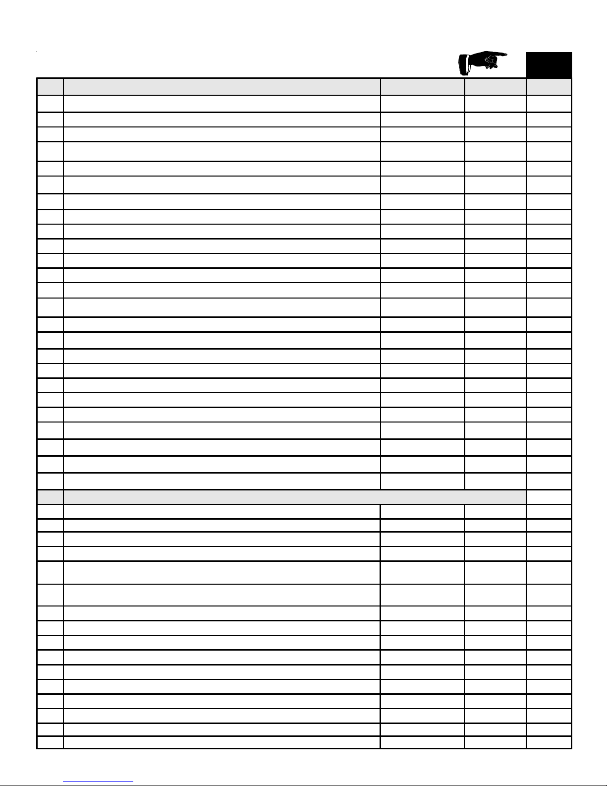
(NG , LP) Service Part s List
IMPORT ANT: THIS IS DA TED INFORMA TION. The most current information is located on your
dealers VIP site. When ordering, supply serial and model numbers to ensure correct service parts.
ITEM STANDING PI LOT IG NITIO N SERIAL # PART NUMBER
Burner Orifice NG (#44C) 582-844 Y
Burner Orifice LP (#54C) 582-854 Y
1 Junction B ox 100-250A Y
2Burner
3 Glass Door Assembly GLA-550TR Y
4Log Grate 2014-001
5 Base Refractory NG, LP 2013-100
6 Log S e t Assembly LOGS-2013 Y
7Log 1 SRV2014-701
8Log 2 SRV2014-703
9Log 3 SRV2014-702
10 Log 4 SRV780-707
11 Log 5 SRV2014-704
12 Refractory Kit (Sold as set only) BRICK-296
13 Andirons, Cast 80784
Pilot Tube
Lava Rock Bag 060-721
Mineral Wo o l 050-721
Exhaust Res tric t or 530-299
Glass L atch As s e m b ly 386-122A Y
Touch Up P ai nt TUP-GBK-12
Regulator NG
Regulator LP
Pilot Spud NG
Pilot Spud LP
ACCESSORIES
Fan Kit GFK-160A
Extend ed Ve r tical Baffle Ki t BAF-VERT
Wall Switc h K it, Off-white WSK-21-HTI
Wall Switch Kit, White WSK-21-W-HTI
Conversion Kit NG
Conversion Kit LP
Door Front - Remington Ave. DF-32RA-BK
Door Front - Remington Ave. DF-32RA-HP
Door Front - Sun P rairie Operable DF-32SPO-BK
Door Front - Sun P rairie Operable DF-32SPO-HP
Door Front - Sun P rairie Operable DF-32SPO-VC
Door Front - Town Square DF-32TS-BK
Door Front - Town Square DF-32TS-HP
Door Front - Harmony Hall DF-32HH-BK
Hood , Blac k SRV550-175
Hood , Hamme red P ewter SRV550-175-HP
Pre 10-06
Post 10-06
Pre 10-06
Post 10-06
Pre 10-06
Post 10-06
Pre 10-06
Post 10-06
Pre 10-06
Post 10-06
Pre 10-06
Post 10-06
Pre 10-06
Post 10-06
Pre 10-06
Post 10-06
2013-002
2013-018
SRV485-301
N/A
060-518
230-1570
060-519
230-1520
446-505
2103-116
446-517
2103-117
NGK-2013
NGKS-2013
LPK-2013
LPKS-2013
QV32B
AVAILAB LE
TO SHIP IN
24 HOURS
Y
Y
Y
Y
Y
Y
Y
Y
Y
Y
Y
Y
Y
Y
Y
5Quadra-fire • QV32B, QV36B • 2013-900 Rev. F • 9/06
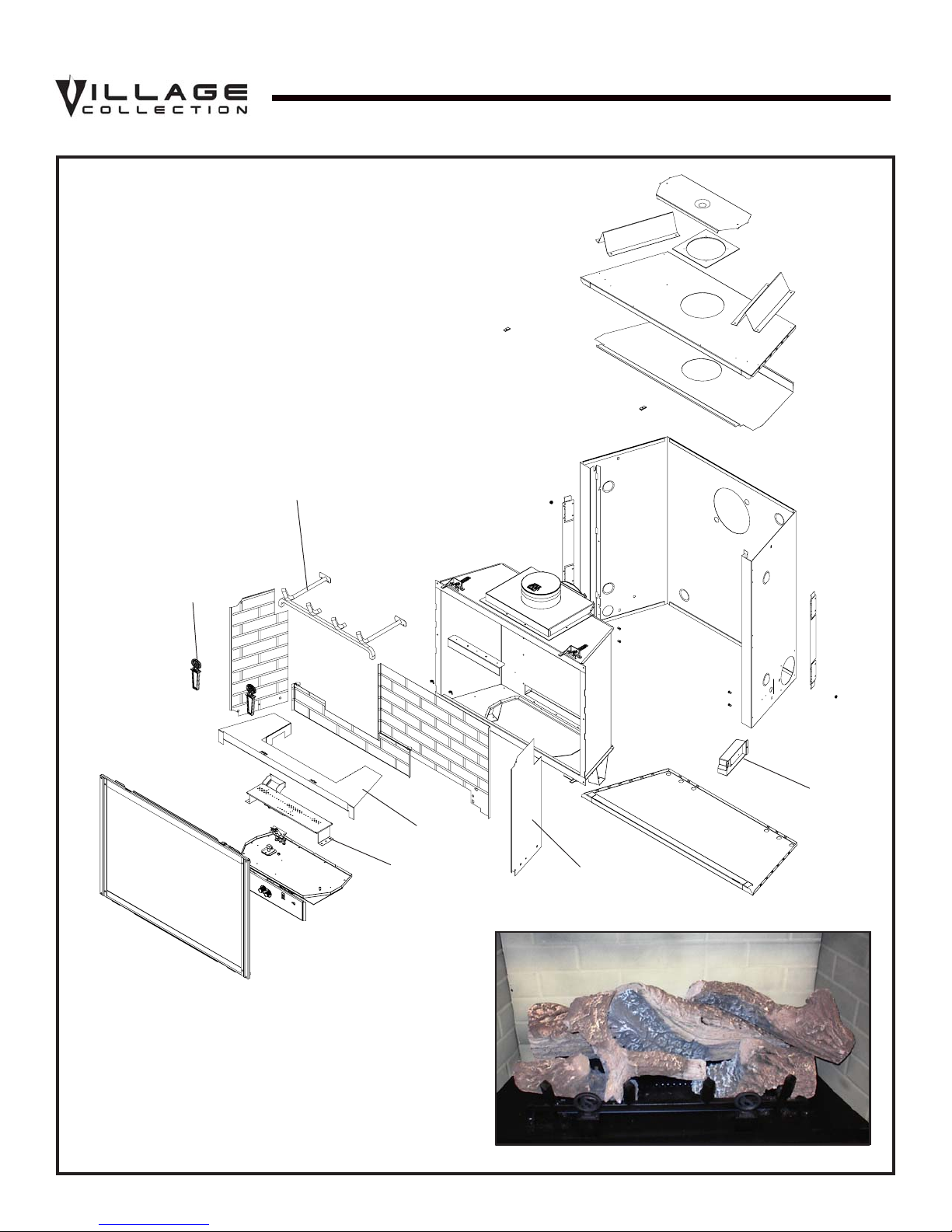
Service Parts
QV36B
(NG , LP) Exploded Parts Diagram
4
Beginning Manufacturing Date: 6-03
Ending Manufacturing Date: ______
3
1
5
2
12
6 Log Set Assembly
7
10
Part number list on following page.
*
Î
6 Quadra-fire • QV32B, QV36B • 2013-900 Rev. F • 9/06
9
11
8
(NG, LP) Service Parts List /
IMPORT ANT: THIS IS DA TED INFORMATION. The most current information is located on your
dealers VIP site. When ordering, supply serial and model numbers to ensure correct service parts.
ITEM STANDING PI LOT IGNITION SERIAL # PART NUMBER
Burner Orifice NG (#43C) 582-843 Y
Burner Orifice LP (#53C) 582-853 Y
1 Junc t ion Bo x 100-250A Y
2 Burner
3 Andirons, Cast 80784
4 Log Grate 2014-001
5 Base Refractory NG, LP 2015-100
6 Log Set Assembly LOGS-2015 Y
7 Log 1 SRV2016-701
8 Log 2 SRV2014-703
9 Log 3 SRV2014-703
10 Log 4 SRV780-707
11 Log 5 SRV700-706
12 R e fr acto ry K it (Sold as set only) BRICK-294
Glass Door Assembly GLA-750TR Y
Pilot Tube
Lava Rock Bag 060-721
Mineral Woo l 050-721
Exhaus t R es t ri ctor 530-299
Glass Latch Assembly 386-122A Y
Touc h U p Pa int TUP-GBK-12
Regulator NG
Regulator LP
Pilot Spud NG
Pilot Spud LP
ACCESSORIES
Fan Kit GFK-160A
Extended Vertical Baffle Kit BAF-VERT
Wall Switch Kit, O ff- white WSK-21-HTI
Wall Switc h Kit, White WSK-21-W-HTI
Conversion Kit NG
Conversion Kit LP
Do or F r ont - Remington Ave. DF-32RA-BK
Do or F r ont - Remington Ave. DF-32RA-HP
Door Front - Sun Prairie Operable DF-32SPO-BK
Door Front - Sun Prairie Operable DF-32SPO-HP
Door Front - Sun Prairie Operable DF-32SPO-VC
Door Fro nt - Town Square DF-32TS-BK
Door Fro nt - Town Square DF-32TS-HP
Door Fro nt - Ha rmony Hall DF-32HH-BK
Hood, Black SRV550-175
Hood, Hammered Pewter SRV550-175-HP
Pre 10-06
Post 10-06
Pre 10-06
Post 10-06
Pre 10-06
Post 10-06
Pre 10-06
Post 10-06
Pre 10-06
Post 10-06
Pre 10-06
Post 10-06
Pre 10-06
Post 10-06
Pre 10-06
Post 10-06
2015-002
2015-016
SRV485-301
N/A
060-518
230-1570
060-519
230-1520
446-505
2103-116
446-517
2103-117
NGK-2015
NGKS-2015
LPK-2015
LPKS-2015
QV36B
AVAILABLE
TO SHIP IN
24 HOURS
Y
Y
Y
Y
Y
Y
Y
Y
Y
Y
Y
Y
Y
Y
Y
7Quadra-fire • QV32B, QV36B • 2013-900 Rev. F • 9/06
Service Parts
QV32B, QV36B
Standing Pilot Ignition
Valve Assembly
13
7
11
12
1
(NG , LP) Exploded Parts Diagram
5
8
9
10
Beginning Manufacturing Date: 7-03
6
4
3
2
AVAILABLE
TO S HIP IN
24 HOURS
ITEM DESCRIPTION SERIAL # PART NUMBER
1 ON/OFF Rocker Switch 060-521A Y
2Valve NG
2Valve LP
3 Flexible Gas Connector 530-302A Y
4 Burner Plate Gasket 530-431
5 Burner Neck Gasket 2045-407
6Pilot Assembly NG
6Pilot Assembly LP
7Piezo Ignitor 291-513 Y
8 Valve Bracket / SIT Bracket ADP
9 Flex Ball Valve Assembly 302-320A Y
10 Jumper Wire 049-552A Y
11 Pilot Cont r ol Knob
12 Flame Cont rol Knob
13 Control Panel
Pilot Brac ket
PRE 10-06
POST 10-06
PRE 10-06
POST 10-06
PRE 10-06
POST 10-06
PRE 10-06
POST 10-06
PRE 10-06
POST 10-06
PRE 10-06
POST 10-06
PRE 10-06
POST 10-06
PRE 10-06
POST 10-06
PRE 10-06
POST 10-06
060-522
230-0710
060-523
230-0720
530-510A
2103-010
530-511A
2103-011
2025-101
2025-101/2044-155
291-530
571-534
291-531
571-533
291-119
291-125
530-164
N/A
Y
Y
Y
Y
Y
Y
Y
Y
8 Quadra-fire • QV32B, QV36B • 2013-900 Rev. F • 9/06

1
Approvals and Codes
Appliance Certification
The Village Collection fireplace models discussed in this
Installers Guide have been tested to certification
standards and listed by the applicable laboratories.
Certification
MODELS: QV32B, QV36B
LABORA TORY : Underwriters Laboratories
TYPE: Direct Vent Gas Fireplace Heater
ST ANDARD:
ANSI Z21.88 -2000•CSA2.33-2000•UL307B
NOTE: THESE MODELS ARE UL LISTED TO UL307B,
THE STANDARD FOR GAS-BURNING HEATING APPLIANCES FOR MANUFACTURED HOMES AND RECRE-
ATIONAL VEHICLES.
Installation Codes
The fireplace installation must conform to local codes.
Before installing the fireplace, consult the local building
code agency to ensure that you are in compliance with all
applicable codes, including permits and inspections.
High Altitude Installations
U.L. Listed gas appliances are tested and approved without
requiring changes for elevations from 0 to 2,000 feet in the
U. S. A. and in Canada.
When installing this appliance at an elevation above 2,000
feet, it may be necessary to decrease the input rating by
changing the existing burner orifice to a smaller size. Input
rate should be reduced by 4% for each 1000 feet above a
2000 foot elevation in the U.S.A. or 10% for elevations
between 2000 and 4500 feet in Canada. If the heating value
of the gas has been reduced, these rules do not apply . To
identify the proper orifice size, check with the local gas
utility.
If installing this appliance at an elevation above 4,500 feet
(in Canada), check with local authorities.
In the absence of local codes, the fireplace installation
must conform to the National Fuel Gas Code ANSI Z223.1
(in the United States) or the CAN/CGA-B149 Installation
Codes (in Canada). The appliance must be electrically
grounded in accordance with local codes or, in the absence
of local codes with the National Electric Code ANSI/NFPA
No. 70 (in the United States), or to the CSA C22.1
Canadian Electric Code (in Canada).
These models may be installed in a bedroom or bed-sitting
room in the U.S.A. and Canada.
9Quadra-fire • QV32B, QV36B • 2013-900 Rev. F • 9/06

NOTE: The following requirements reference various
Massachusetts and national codes not contained in this
document.
Î
Requirements for the Commonwealth of
Massachusetts
For all side wall horizontally vented gas fueled equipment
installed in every dwelling, building or structure used in
whole or in part for residential purposes, including those
owned or operated by the Commonwealth and where the
side wall exhaust vent termination is less than seven (7)
feet above finished grade in the area of the venting, including but not limited to decks and porches, the following requirements shall be satisfied:
Installation of Carbon Monoxide Detectors
At the time of installation of the side wall horizontal vented
gas fueled equipment, the installing plumber or gasfitter
shall observe that a hard wired carbon monoxide detector
with an alarm and battery back-up is installed on the floor
level where the gas equipment is to be installed. In addition, the installing plumber or gasfitter shall observe that a
battery operated or hard wired carbon monoxide detector
with an alarm is installed on each additional level of the
dwelling, building or structure served by the side wall horizontal vented gas fueled equipment. It shall be the responsibility of the property owner to secure the services of qualified licensed professionals for the installation of hard wired
carbon monoxide detectors.
In the event that the side wall horizontally vented gas fueled equipment is installed in a crawl space or an attic, the
hard wired carbon monoxide detector with alarm and battery back-up may be installed on the next adjacent floor
level.
In the event that the requirements of this subdivision can
not be met at the time of completion of installation, the
owner shall have a period of thirty (30) days to comply with
the above requirements; provided, however, that during said
thirty (30) day period, a battery operated carbon monoxide
detector with an alarm shall be installed.
Approved Carbon Monoxide Detectors
Each carbon monoxide detector as required in accordance
with the above provisions shall comply with NFP A 720 and
be ANSI/UL 2034 listed and IAS certified.
Inspection
The state or local gas inspector of the side wall horizontally
vented gas fueled equipment shall not approve the installation unless, upon inspection, the inspector observes carbon
monoxide detectors and signage installed in accordance with
the provisions of 248 CMR 5.08(2)(a)1 through 4.
Exemptions
The following equipment is exempt from 248 CMR 5.08(2)(a)1
through 4:
• The equipment listed in Chapter 10 entitled “Equipment
Not Required To Be Vented” in the most current edition
of NFP A 54 as adopted by the Board; and
• Product Approved side wall horizont ally vented gas fueled equipment installed in a room or structure separate from the dwelling, building or structure used in whole
or in part for residential purposes.
MANUFACTURER REQUIREMENTS
Gas Equipment Venting System Provided
When the manufacturer of Product Approved side wall horizontally vented gas equipment provides a venting system
design or venting system components with the equipment,
the instructions provided by the manufacturer for installation of the equipment and the venting system shall include:
• Detailed instructions for the installation of the venting
system design or the venting system components; and
• A complete parts list for the venting system design or
venting system.
Gas Equipment Venting System NOT Provided
When the manufacturer of a Product Approved side wall
horizontally vented gas fueled equipment does not provide
the parts for venting the flue gases, but identifies “special
venting systems”, the following requirements shall be satisfied by the manufacturer:
• The referenced “special venting system” instructions shall
be included with the appliance or equipment installation
instructions; and
• The “special venting systems” shall be Product Approved
by the Board, and the instructions for that system shall
include a parts list and detailed installation instructions.
Signage
A metal or plastic identification plate shall be permanently
mounted to the exterior of the building at a minimum height
of eight (8) feet above grade directly in line with the exhaust vent terminal for the horizontally vented gas fueled
heating appliance or equipment. The sign shall read, in
print size no less than one-half (1/2) inch in size, “GAS
VENT DIRECTLY BELOW. KEEP CLEAR OF ALL OBSTRUCTIONS”.
10 Quadra-fire • QV32B, QV36B • 2013-900 Rev. F • 9/06
A copy of all installation instructions for all Product Approved side wall horizontally vented gas fueled equipment,
all venting instructions, all parts lists for venting instructions, and/or all venting design instructions shall remain
with the appliance or equipment at the completion of the
installation.
See Gas Connection section for additional Commonwealth of Massachusetts requirements.

2
Getting Started
Introducing the Village Collection
Gas Fireplaces
The Village Collection direct vent gas fireplaces are designed to operate with all combustion air siphoned from
outside of the building and all exhaust gases expelled to
the outside.
The information contained in this Installers Guide, unless
noted otherwise, applies to all models and gas control
systems. Gas fireplace diagrams, including the
dimensions, are shown in this section.
Pre-install Preparation
This gas fireplace and its components are tested and safe
when installed in accordance with this Installers Guide.
Report to your dealer any parts damaged in shipment,
particularly the condition of the glass. Do not install any
unit with damaged, incomplete, or substitute parts.
The vent system components and trim doors are shipped
in separate packages. The gas logs are packaged
separately and must be field installed.
Read all of the instructions before starting the
installation. Follow these instructions carefully during
the installation to ensure maximum safety and benefit.
Failure to follow these instructions will void the
owner’s warranty and may present a fire hazard.
The Quadra-Fire Warranty will be voided by , and Hearth &
Home Technologies disclaims any responsibility for, the
following actions
• Installation of any damaged fireplace or vent system
component.
• Modification of the fireplace or direct vent system.
• Installation other than as instructed by Hearth & Home
Technologies.
• Improper positioning of the gas logs or the glass door.
• Installation and/or use of any component part not manu-
factured and approved by Hearth & Home T echnologies,
not withstanding any independent testing laboratory or
other party approval of such component part or accessory.
ANY SUCH ACTION MAY POSSIBLY CAUSE A FIRE
HAZARD.
When planning a fireplace installation, it’s necessary to
determine:
• Where the unit is to be installed.
• The vent system configuration to be used.
• Gas supply piping.
• Electrical wiring.
• Framing and finishing details.
• Whether optional accessories—devices such as a fan,
wall switch, or remote control—are desired.
If the fireplace is to be installed on carpeting or tile, or on
any combustible material other than wood flooring, the
fireplace should be installed on a metal or wood panel that
extends the full width and depth of the fireplace.
11Quadra-fire • QV32B, QV36B • 2013-900 Rev. F • 9/06

15 3/8
(391mm)
30 3/4
(781mm)
1/2
(13mm)
40
(1016mm)
GAS
LINE
ACCESS
2 3/16
(55mm)
5 1/16
(129mm)
15 7/8
(403mm)
34 5/8
(879mm)
36 1/8
(917mm)
40 7/8
(1039mm)
Ø 6 5/8
(168mm)
8 13/16
(224mm)
(526mm)
20 3/4
16 3/8
(416mm)
3 9/16
(90mm)
6 7/8
(174mm)
Ø 8
(203mm)
ELECTRICAL
ACCESS
37 7/8
(961mm)
GAS
ACCESS
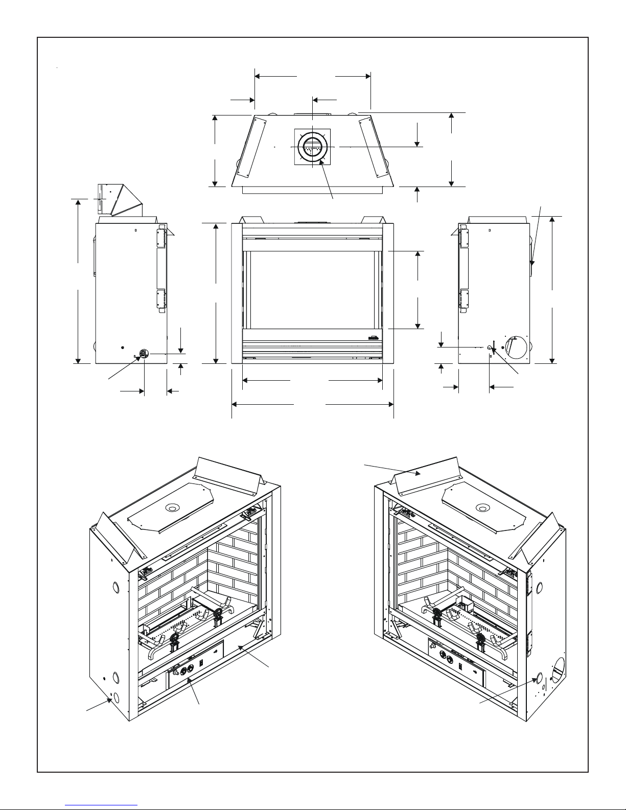
Figure 2. Diagram of the QV32B
Î
CONTROLS
12 Quadra-fire • QV32B, QV36B • 2013-900 Rev. F • 9/06
RATING PLATE/LABELS
GAS
TOP STANDOFFS
ELECTRICAL
ACCESS
12 7/8
(326mm)
25 3/4
(653mm)
36 7/16
(925mm)
GAS LINE
ACCESS
2 3/16
(55mm)
5 1/16
(129mm)
15 7/8
(402mm)
31 1/8
(790mm)
31
(790mm)
36
(913mm)
5/8 (168mm)
Ø6
8 13/16
(223mm)
17 1/4
(438mm)
16 3/8
(414mm)
3 9/16
(90mm)
6 7/8
(174mm)
Ø 8
(203mm)
32 9/16
(828mm)
ELECTRICAL
ACCESS
GAS
ACCESS
GAS
CONTROLS
RATING PLATE/LABELS
TOP STANDOFFS
ELECTRICAL
ACCESS
Î
Figure 2. Diagram of the QV32B
13Quadra-fire • QV32B, QV36B • 2013-900 Rev. F • 9/06
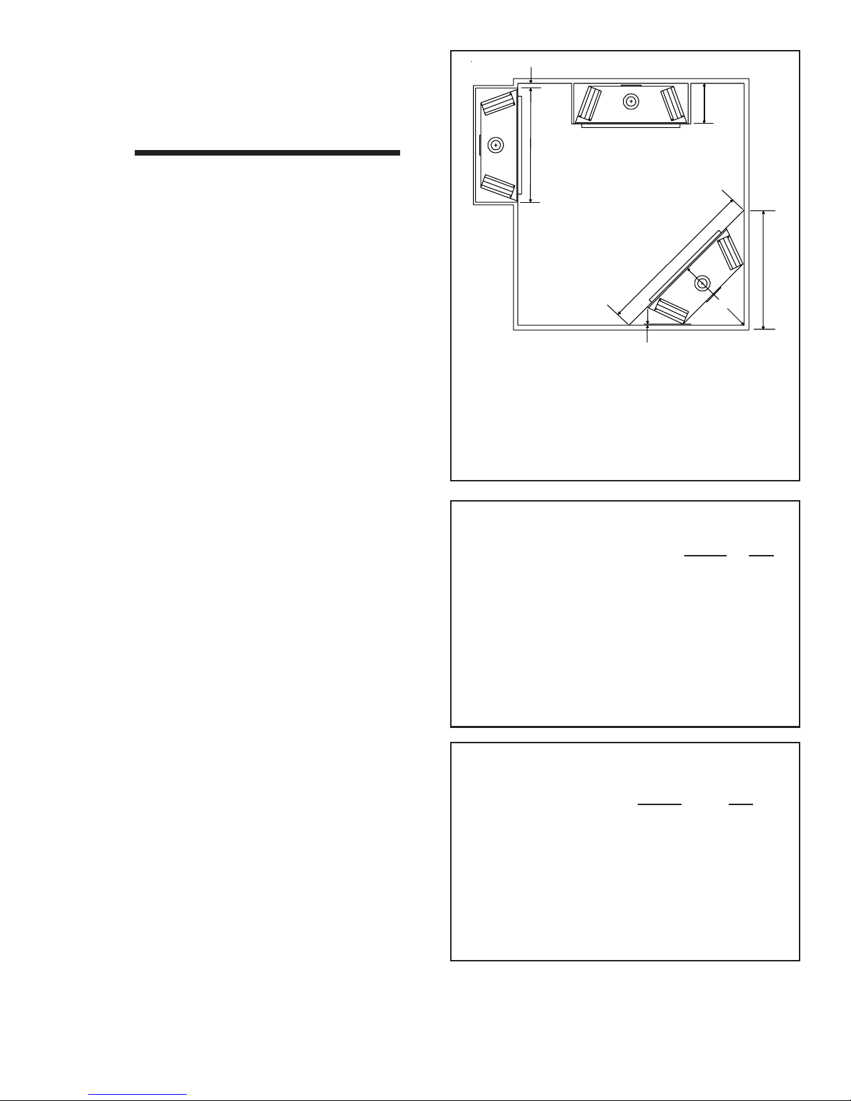
3” MIN. (76mm)
B
Installing the Fireplace
3
Constructing the Fireplace Chase
A chase is a vertical box-like structure built to enclose the
gas fireplace and/or its vent system. Vertical vents that run
on the outside of a building may be, but are not required to
be, installed inside a chase.
CAUTION: TREATMENT OF FIRESTOP SPACERS AND
CONSTRUCTION OF THE CHASE MAY VARY WITH THE
TYPE OF BUILDING. THESE INSTRUCTIONS ARE NOT
SUBSTITUTES FOR THE REQUIREMENTS OF LOCAL
BUILDING CODES. THEREFORE, YOUR LOCAL BUILDING CODES MUST BE CHECKED TO DETERMINE THE
REQUIREMENTS FOR THESE STEPS.
Factory-built fireplace chases should be constructed in
the manner of all outside walls of the home to prevent cold
air drafting problems. The chase should not break the outside building envelope in any manner.
This means that the walls, ceiling, base plate and cantilever floor of the chase should be insulated. Vapor and air
infiltration barriers should be installed in the chase as per
regional codes for the rest of the home. Additionally, we
recommend that the inside surfaces be sheetrocked and
taped for maximum air tightness.
T o further prevent draft s, the firestops should be caulked to
seal gaps. Gas line holes and other openings should be
caulked or stuffed with insulation. If the unit is being installed on a cement slab, we recommend that a layer of
plywood be placed underneath to prevent conducting cold
up into the room. Be sure to include spark arrestors for
woodburning units if they are required.
A
E
D
C
1/2 “ MIN. (13mm)
ABC*D*E*
QV36B 42” 16 1/4” 31 7/8” 45” 63 3/4”
QV32B 37” 16 1/4” 29 3/8” 41 1/2” 58 3/4”
Note: *If venting with (2) 900 elbows off rear of unit
the dimensions C, D and E will change.
Figure 3. Fireplace Dimensions, Locations,
and Space Requirements
Minimum Clearances
from the Fireplace to Combustible Materials
Inches mm
Glass Front......................................36........ 914
Floor .................................................0........... 0
Rear ............................................... 1/2 ........ 13
Sides .............................................. 1/2 ........ 13
T op (QV32B).................................1 1/2 ....... 38
(QV36B)................................ 3 1/4....... 83
Ceiling* ............................................31........ 787
* The clearance to the ceiling is measured from the top
of the unit, excluding the standoffs (see Figure 37).
THE CHASE SHOULD BE CONSTRUCTED SO THAT
ALL CLEARANCES TO THE FIREPLACE ARE MAINTAINED AS SPECIFIED WITHIN THIS INSTALLERS
GUIDE.
Step 1. Locating the Fireplace
Sp ace and clearance requirements for locating a fireplace
within a room (see Figure 3).
Clearance Requirements
The top and back of the fireplace are defined by standoffs. The minimum clearance to a perpendicular wall
extending past the face of the fireplace is 3 inches (76mm).
The back of the fireplace may be recessed 16 1/4 inches
(413mm) into combustible construction.
The distance from the unit to combustible construction is
to be measured from the unit outer wrap surface to the
combustible construction, NOT from the screw heads that
secure the unit together.
14 Quadra-fire • QV32B, QV36B • 2013-900 Rev. F • 9/06
Minimum Clearances
from the Vent Pipe to Combustible Materials
Inches mm
Vertical Sections. ............ 1 ................ 25
Horizontal Sections
Top .................................... 3 ................ 75
Bottom............................... 1 ................ 25
Sides ................................. 1 ................ 25
At Wall Firestops
Top ................................. 2 1/2 ............63.7
Bottom..............................1/2............... 13
Sides ................................. 1 ................ 25
For minimum clearances, see the direct vent termination
clearance diagrams in Figures 29 and 30 in this manual.
 Loading...