

Page 1
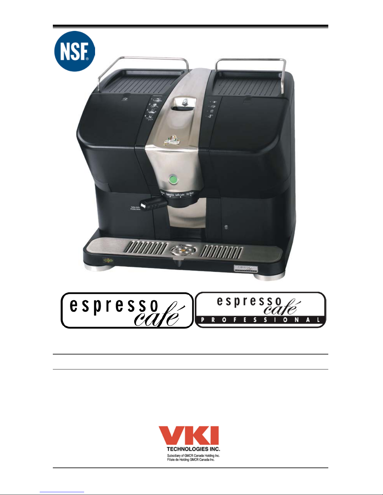
VKI Publication # 100218-001 February 2012
Oper atio n & Service M anual
Page 2

2
Contents
Safety In fo rmatio n ......................................................................... 4
Coffee Maker Specifications.......................................................... 6
Coffee Maker Overview ................................................................. 8
Parts Ident ificat ion ................................................................................................8
System St at us LED I ndicator Panel ..................................................................9
Produc t Selec ti on Handle ....................................................................................9
Pod Slot Cover (Pr ofessional M odel Only) .....................................................10
Cup Warmers (Profe s si onal M odel Only) .......................................................10
Connecting to a W ate r S upply..................................................... 11
Drain Installation ......................................................................... 13
Installing the Milk Canister .......................................................... 15
Using the Co ffee Maker ............................................................... 16
Coffee Pods .........................................................................................................16
Brewing a Beverage ...........................................................................................16
Type s of Beverages Available ..................................................... 17
Connecting the Progra m m er ....................................................... 18
Power-Up Diagnostic Routine...........................................................................19
Software Features ....................................................................... 20
Sof tware Menu Navigation ................................................................................20
Downloadi ng S oftwa re Update s .................................................. 23
Maintenance ................................................................................ 24
Empty the W aste B in..........................................................................................24
Clea ning a M ilk Overflow...................................................................................24
Empty the Drip Tray ...........................................................................................25
Quick-Rins e Cycle ..............................................................................................26
For c ed Quick -Rinse............................................................................................26
Prim ing the W ater System (on Power-Up) .....................................................27
Di spe nsin g Spout and Pr oduc t T ube P lace ment...........................................27
Usi ng the Cleaning Tab ............................................................... 28
In-Place Cl eaning (Sanit izing Cy c le) ...............................................................28
Emptying the Milk and Water Using the Clea ning Tab .................................31
Cleani ng the M ilk Conveyor ........................................................ 32
Open the Cover...................................................................................................32
Clea ning the Milk Conveyor Using a Wet/Dr y V ac uum ................................33
Manual Cleani ng of t he Milk Conveyor ...........................................................34
Page 3

3
Contents
Removing the Coffee Maker ........................................................ 37
Empty the Milk Conveyor...................................................................................37
Drain t he Wat er ( Reservoir and Heater) .........................................................38
St or ing the Cof fee Maker...................................................................................39
Genera l Informa tion .................................................................... 40
Replacing Maj or Compone nts ..................................................... 41
Opening the Cover .............................................................................................41
Re moving t he Cover and Contour P anel ........................................................42
Removing the Cover....................................................................................... 42
Removing the Contour Panel ......................................................................... 43
Brewer ..................................................................................................................44
Brewer Heads ................................................................................................ 44
Brewer Motor .......................................................................................................45
Selection Rin g & B oar d......................................................................................45
Water Heater .......................................................................................................46
Temp er ature P r obe ............................................................................................47
Ther m al Cut-Off Switch .....................................................................................47
Water Res er voir ..................................................................................................48
Water Level Float Swit c h...................................................................................49
Inlet Valv e ............................................................................................................50
Outlet Valv es .......................................................................................................51
Rebu ilding an Out let Valve................................................................................52
Contr ol B oard & O ptions Board........................................................................53
Water P ump Assem bly ......................................................................................54
Water P ump H ar ness/Diode-Brid ge A ssembly ..............................................55
Milk Conveyor and Dispenser Mot or ...............................................................56
Whipper Motor .....................................................................................................57
Flow Meter ...........................................................................................................58
Exhaust Fan .........................................................................................................59
M ain Power Switch .............................................................................................60
5 Amp Circuit B r eaker ........................................................................................61
15 Amp Fuse Holder A s se mb ly ........................................................................61
Replacing the 15 Amp Fuse ........................................................................... 61
Power Sup ply ......................................................................................................62
Sensor Boards .....................................................................................................63
Cup Warmer (P r ofessi onal M odel)...................................................................63
Troubleshooting .......................................................................... 64
Error Messages...................................................................................................64
FAQ (Fre quently Asked Question s) ............................................. 67
Page 4

4
Safety Information
Your safety is very important to us. It is imperative that you read and
understand this safety information before
proceeding with the
ins tallation and operation of this coffee maker.
This coffee maker is designed for interior use ONLY and must
never be inst alled outdoor s.
This equipment must be pos itioned so that the wall plug and the
main power switch are both easily accessib le.
Do n ot c onne ct the coffee maker to a volta ge supply ot her tha n the
voltage ind icated on the serial number decal.
Do not im me r s e t h is coffee maker or any pa rt of this e qu ipme nt in
liquid.
This coffee maker must be installed securely on a level surface. If it
does not appear to be a stable location, select another installation
location.
Whe n the coffee maker is sw it che d ON , a s mal l quantit y of wa te r
may be dispens ed as t he system is pur ged. T his w ate r may be hot so
keep clear of the dispensing area.
To pr event s erious in jury or bur ns, do not place f inge rs direct l y int o
the c offee pod slot a nd do not place any pa rt of your body d ir ec tly
ove r the coffee pod slot.
Keep hands clear of the dispensing area at the front of the coffee
maker. Liquids be ing d ispensed are extremely hot and can cause
severe burns.
Never disc onnec t the coffee maker by pu ll in g o n the se rvice cord,
a nd never us e t he coffee maker if the service cord is damaged.
Never a tte mpt to ove rr ide the sa fe ty f ea tur es inc orpor at ed int o the
e qui pment . T hey are there f or your prot ection and should never be
bypass ed under any circ umstance s.
This equipment must be used specifically for the purpose for
which it is designed. The manufacturer is not responsible for
damage or injury resulting from improper use of this equipment.
Page 5

5
Safety Information
Always switch the power OFF and disconnect the service cord
whe n c le a ning t he inte ri or of t he coffee maker. Compone nts ins ide
the coffee maker can cause electrical shock resulting in personal
injury.
If the coffee maker is not working properly or appears to have a
fa ult , s witc h off the pow e r, d is con ne ct the se rvice c ord a nd cal l a n
authorized technician immediately for service. Only qualified
per sonn el sh ould p erform ser vice on this equipm ent.
The major ity of the electrical c om ponent s in the E spr es so C af é are
low vo lta ge (and not
120 vo lts AC). Never connect these electrical
c omponent s t o 120 vo lts AC.
The wa ter s ys tem in this coffee maker is pressurized dur ing a br ew
cycle. T his pres sure must be released usin g t he drai n ins ert prior to
servicin g t he syst em.
Use caution when servicing the water heater or the outlet valves as
they may be ext reme ly hot and can cause s ever e burns .
Us e caut io n whe n w orking ins ide the coffee maker as t here ma y be
sharp edges on s ome components t hat can cause cuts.
To prevent electrical shock, remo ve all jewelry (rings, watches, etc.)
when servicing the coffee maker.
Use onl y ori gi nal manufac ture r repl ace ment parts in t h is coffee
maker. Una pprove d re plac e ment pa rt s ca n res ult i n per sona l inj ury,
fire and/or fur t her damage t o t he equip ment .
Do not lift the coffee maker using the drip tray. Lift the coffee
maker by t he sides only.
Do not allow children to access this equipment. They are not aware
of t he potential dangers that exis t.
NOTE:
Whenever the unit is switched OFF, wait at least 5
seconds b efore switching it ON again.
U nau t ho rized modif icati on s made to t hi s coff ee maker can re sul t
in se r ious pe r s ona l in jury a nd/ or da m a ge to t he e qui pm e nt , a nd
v oids all warran t ies and cert ificati on s.
Page 6

6
Coffee Maker Specifications
Voltage Rating 120 volts AC
Heater Wat tage 1000 watts
Weight 38 lbs (17 kg)
Cup Siz es – Espresso 1.5 fl. oz (45 ml)
– Cappuccino
7.0 fl. oz (210 ml)
– Caffè Latte
7.0 fl. oz (210 ml)
– Ameri cano 6.0 fl. oz (175 ml)
Water Heater Capacity 14 fl. oz (420 ml)
Water Reservoir Capacity 34 fl. oz (1 liter)
Temperature Control
Electronic Temperature Probe
Heating Time
2 minutes after initial installation
Brew Temperature*
194°F (96°C)
Brew Times – Espresso 30 seconds
– Cappuccino 50 seconds
– Caffè Latte 45 seconds
– Ameri cano
50 seconds
Heater Protection
Yes
Overflow Prote ction
Yes
Circuit Protection • 5-amp circuit breaker for electronics, valves &
motors
• 15-amp fuse for heater
Certification • UL Listed • CSA Appro ved
• NSF Approved
*NOTE: For installations at higher elevations, please contact your distributor or the
manufacturer for special “
HIGH ALTITUDE” software.
Coffee Maker Dimensions
Height:
16 ¾ inches (42.5 centimeters)
Width:
20 ⅛ inches (51 centimeters)
Depth:
15 ¼ inches (39 centimeters)
Installation Requirements
Height:
16 ¾ inches (42.5 centimeters)
Width:
20 ⅛ inches (51 centimeters)
Depth:
17 ¾ inches (45 centimeters)
Page 7

7
To ma int a in the NSF Ce r tific a t ion of t his e quipm ent , only origina l
OEM parts must be used. Using parts from an alternate source
wil l void NSF Certi f ication as well as the equ ipment wa rranty.
Page 8
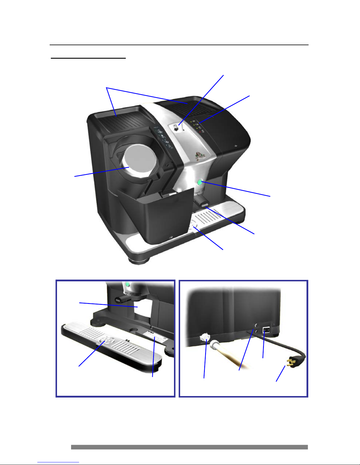
8
Serial Number
Decal
Drip Tray
Waste
Bin
Inlet
Valve
Service
Cord
Pow er
Sw itc h
Fuse &
Circuit
Breaker
Rear View of Machi ne
Coffee Maker Overview
Parts Identification
Coffee Pod Slot
System Status
Indicator Panel
Drip
Tray
START
Button
Product Selection
Handle
Milk
Canister
Receptacle
Cup Warmers
(Professional Model On ly)
Page 9
9
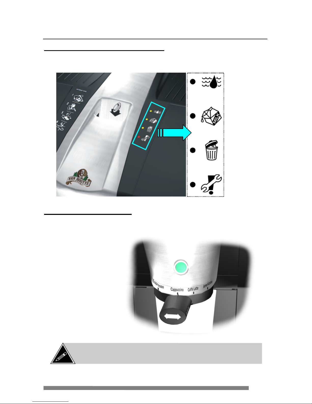
Coffee Maker Overview
System Status LED Indicator Panel
The s ystem status indicator panel (located to the right of the pod slot) provides
inf ormation a bout a ny mai nt e na nc e t ha t may be r e quired.
Product S election Handle
To select a product, move handle left or right until it is aligned with the desired
beverage and press the green
START button to be gin the br e w cycle.
N o w ater –
check water
supply
Replace milk
canister
Em pty w a ste
bin
Call for
Service
*See page 17 for a
descr ipt ion of the
products av ailable.
NOTE: The handle is designed to snap off if it is subjected to too muc h
pressure. If this happens, simply snap it back into pos ition at an upw ard
angle.
Page 10
10
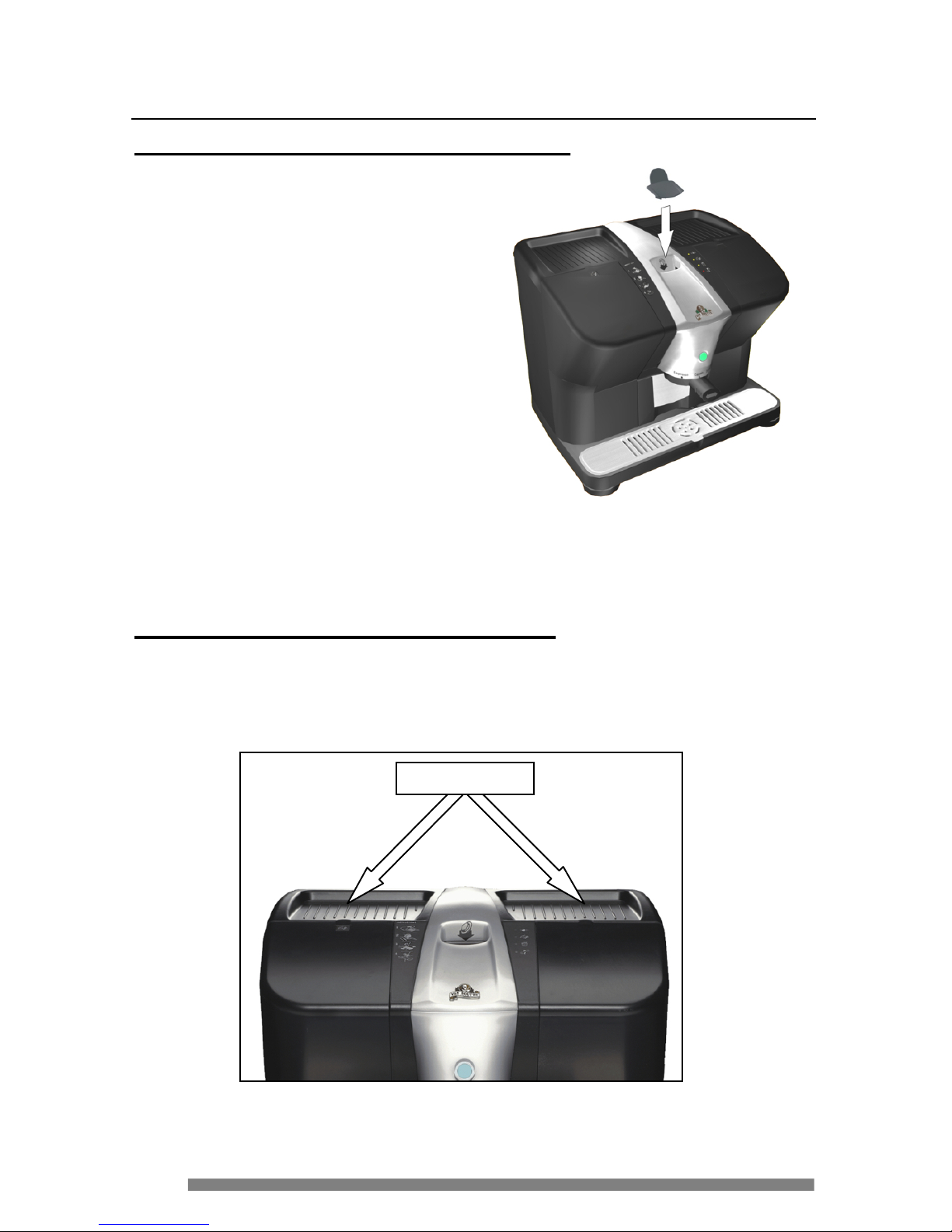
Coffee Maker Overview
Pod Slot Cover (Pro fessional Model Only)
The Espresso Café Professional model
is shipped with a cover for the coffee
pod slot. The cover should remain
installed on the equipment when it is
not in use, and should only be
removed when making a beverage.
After the beverage is prepared, reinstall the pod slot cover to prevent
foreign matter from falling into the
brewer.
Cup Warmers (Professional Model Only )
The Espresso Café Professional model is equipped with cup warmers. Place
glass or ceramic mugs upside down on the cup warmers and leave them in
place unt il the y a re require d (at which time they will be w arm to the t ouc h).
Cup Warmers
Page 11
11
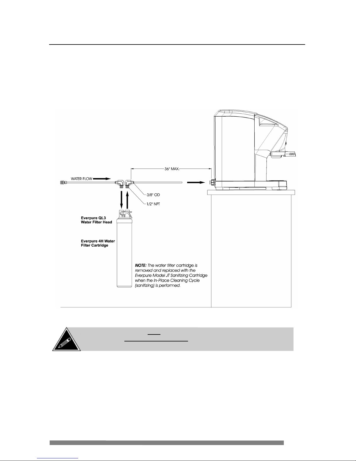
Connecting to a Water Supply
All Espresso Café machines mus t be installed with an Everpure water filtration
system. This system consists of a QL3 filter head (with shut-off valve) and 4H
water filter cartridge. This system is compatible with the Everpure Model JT
Sanitizing Cartridge, which is required to perform the In-Place Cleaning
(sanitizi ng) Cycle in compliance with NSF standards.
NOTE: The water filter must be installed between the water source and the
coffee maker (maximum 3 feet away). Also note that the inlet valve is
equipped with a flo w regulator and back flo w p revention system .
Page 12
12
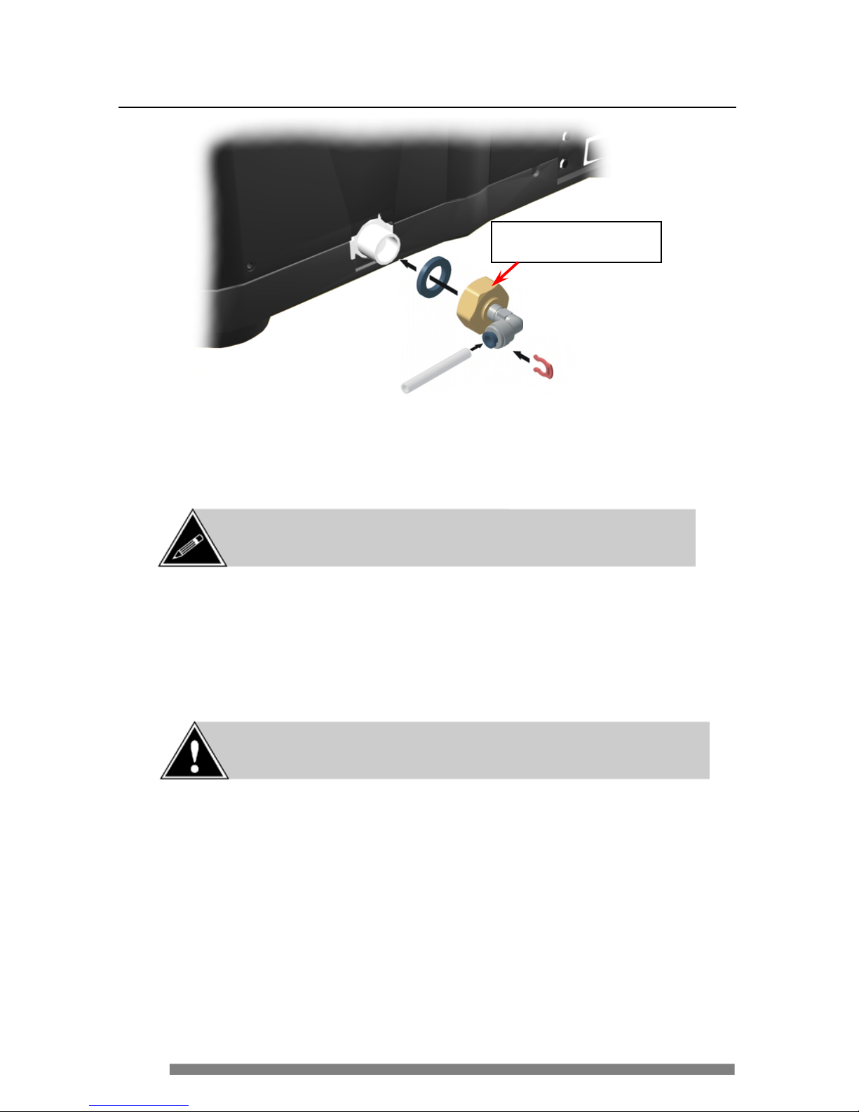
Connecting to a Water Supply
1. C onnect a ¾” inle t fitti ng to t he inl e t va lve at the rea r of the coffee make r,
maki ng c e rtain the rubber w a sher is inserted be tween the fitt ing and the
inlet valve.
2. Tighten the fitting onto the inlet valve – hand-tig hten only. Connect t he
water tubing to the fitting and install the lock clip to lock it in place.
3. Turn the water on at the source, check for l eaks and repai r, if necessary.
4. P lug the ser vice cord into a wa l l outl e t a nd switch ON the power to the
coffee ma ker.
5. C heck for leaks once more and repai r, if necessary.
NOTE: Installation of this equipment must comply w ith all local,
state/provincial and federal plumbing codes.
CAUTION: Place a cup o n the drip t ray w hen the co ffee maker is
init ially f illed with wate r. Approximately 50 ml (1.7 oz) of water will
be dispensed by the spout due to the purging of the water system .
* Illustration is for refer ence
purposes only.
Do not over-tighten the inlet
fitting as this may prevent water
fr om entering the inlet valve.
Page 13
13
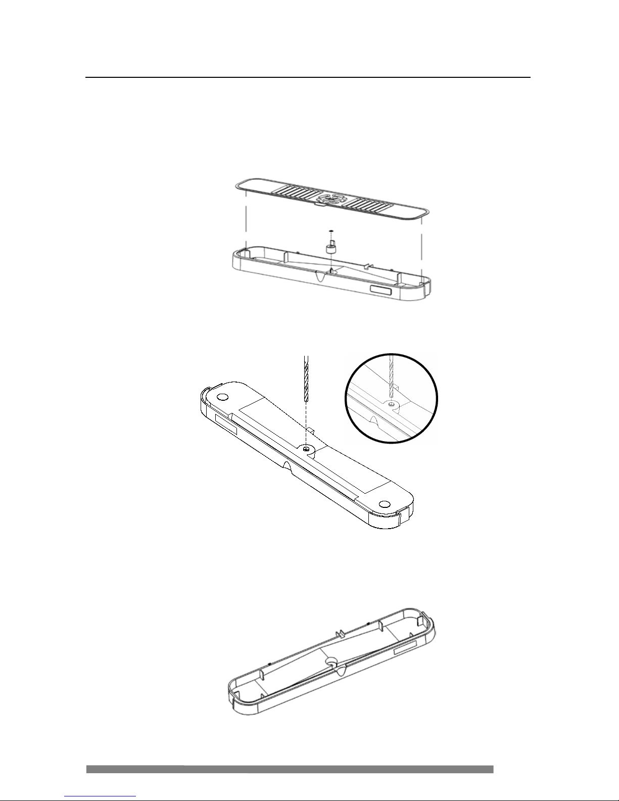
Drain Installation
To ins tall a drain kit on an Es pres so Café, the drip tray mus t first be modified to
r emove the float post and create a drai n hole.
1. Remove the drip tray grill .
2. Remove the retaining clip that sec ures the floa t to t he post.
3. Remove the float.
4. Turn the drip tray upside down.
5. Using a ¼” drill bit, align the bit in the ce nt e r guide of the drip tra y a nd
carefully drill a pilot hole.
6. Change t o a 3/8” drill bit and ca refully drill another hole where the pilot
hole was drill ed to enlarge it.
7. This r emoves the float post f rom the drip tray and creates a channel for the
dr a in syst e m.
Page 14
14
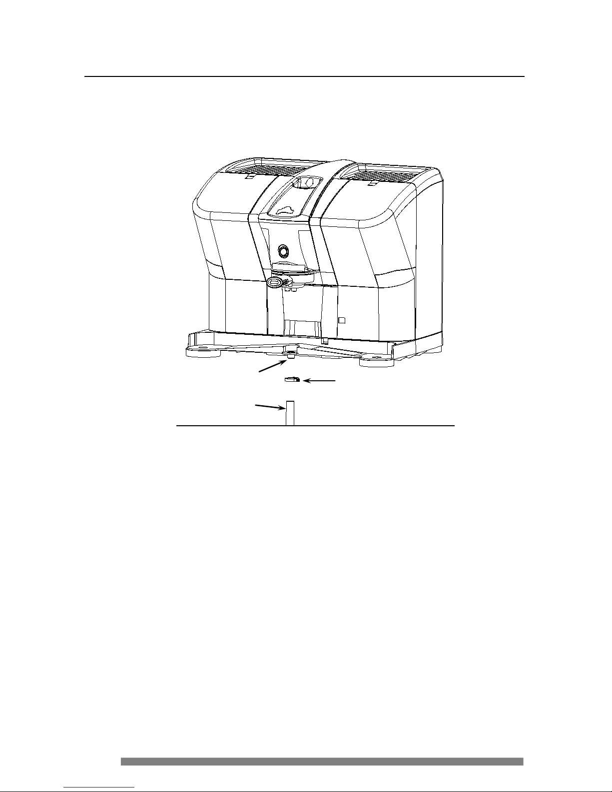
Drain Installation
8. Connect the d rain hose to the drai n fitt ing under the front of the machine.
The hose must g o straight down – d o not route the hose un de rneath the
machine.
9. S e c ure the drain hose to the fitting with the plastic clamp.
10. Conn e c t t he other e nd of the ho se to t he drai n syste m that will be used at
the installation location.
11. Conn e c t t he programmer and power u p the machine.
12. Scroll to the “
DRAIN INSTALLED?” menu and press t he green < START>
button on the machine.
13. Press the “+” butt on on the progra mmer – the lower li ne on t he display
should re a d “
YES ”.
T his lets the s oftware kn ow that a drain is installed, reducin g user
interaction with th e e q uipme nt during an “
IN-PLACE
CLEANING
/SANITIZING CYCLE” , should this cycle ever be required.
14. Press the “
SCROLL UP” button to save the setting.
Plastic Clamp
Drain Hose
Drain Fitting
Page 15
15
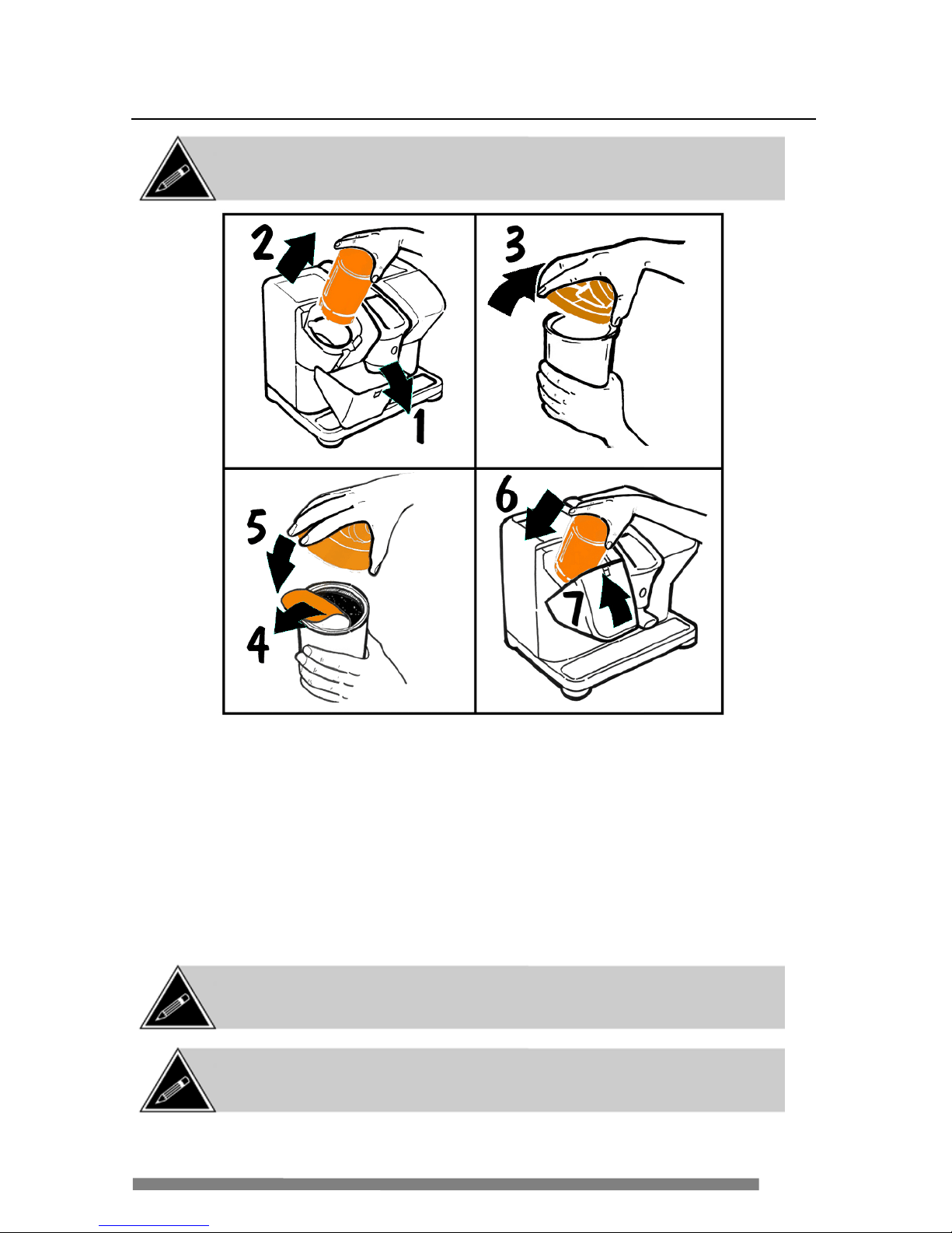
Installing the Milk Canister
1. O pen the milk door on the top lef t of the coffee ma ker.
2. Pull the empty milk canister str aight out (if replac ing).
3. Remove the canister lid from the em pty canister.
4. R emove the fr eshness se al from the new milk cani ster.
5. Install the canister li d ont o th e ne w milk can ister.
6. I nstall the new milk canister into the coffee ma ker by pushing it down into
the canister receptacl e.
7. Close the milk door on the coffee ma ker.
NOTE: Do not install and remove the milk canister repeatedly as this will pack
the mi lk at the bott om of the auger and may c ause it to ja m. Once ins talled,
leave it in place until it is absolutely necessary to remove it.
NOTE: When the milk canister is empty, any selections requiring milk are
disabled and the green START button wil l not ill um inate.
NOTE: When the milk c anister is initially inst alled, or when it is r eplac ed, the
mi lk dispens er motor may automatically activate to prime the milk thr ough the
system. Once primed, the motor will stop automatically.
Page 16
16
Using the Coffee Maker
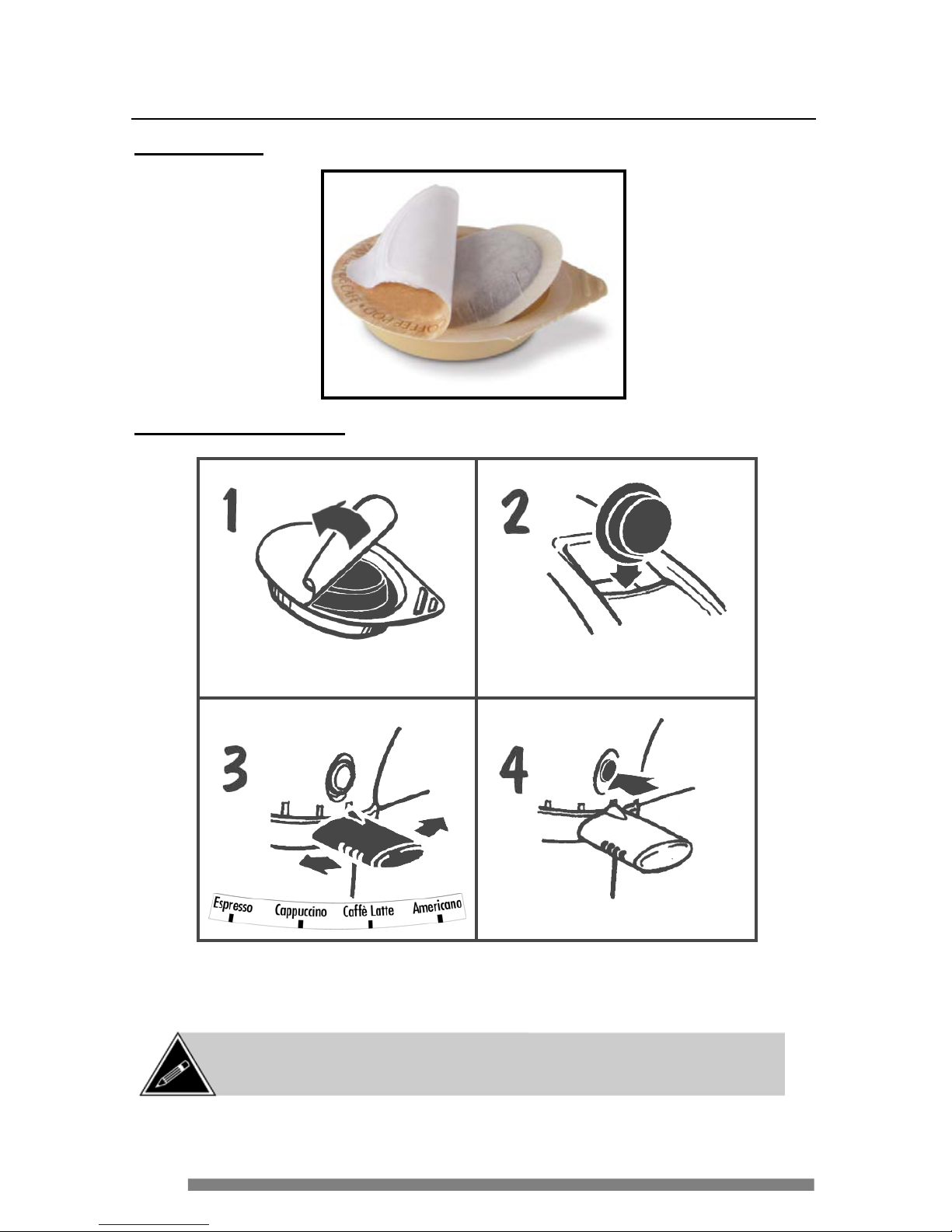
Coffee Pods
Brewing a Beverag e
NOTE: Never ins ert a coff ee pod into the pod s lot w hile the coffee maker is
already in the proc ess of preparing a bev erage. Do not ins ert def ormed c off ee
pods into the slot as they could get jammed in the brewer.
Open the pod package
and r em ove the pod .
Drop the pod into the slot
on top of the coffee maker.
Select the desired product
by moving the selection
handle to the lef t or right.
Press the green START
butto n located above the
selection handle.
Single Dose Coffee Pod & Packaging
Page 17
17
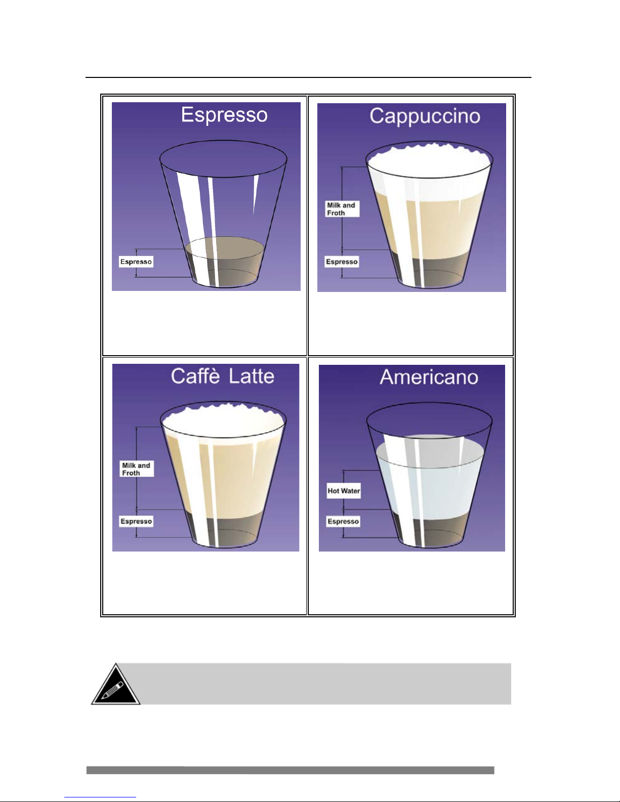
Types of Beverages Available
Espresso – The or iginal, with
intense l ong-
la sting flavors, c r owned
with a golden foam ca lled crema
Cappuccino – A single espresso
topped with hot milk and milk froth
Caffè Latte – A sing le Espresso
blen ded with a generous portion of
creamy hot milk
Americano* (Regular Model Only) – A
single e spresso m ixed with hot
water
*this option app lies only to the Regular Model. The “Americano” beverage is replaced
by “Hot Wa te r” on the Professional Model.
NOTE: The illustrations above are intended to be used simply as a description
of the pr oduct . The finished pr oduc ts may not look exac tly as s how n in these
illustrations.
Page 18
18
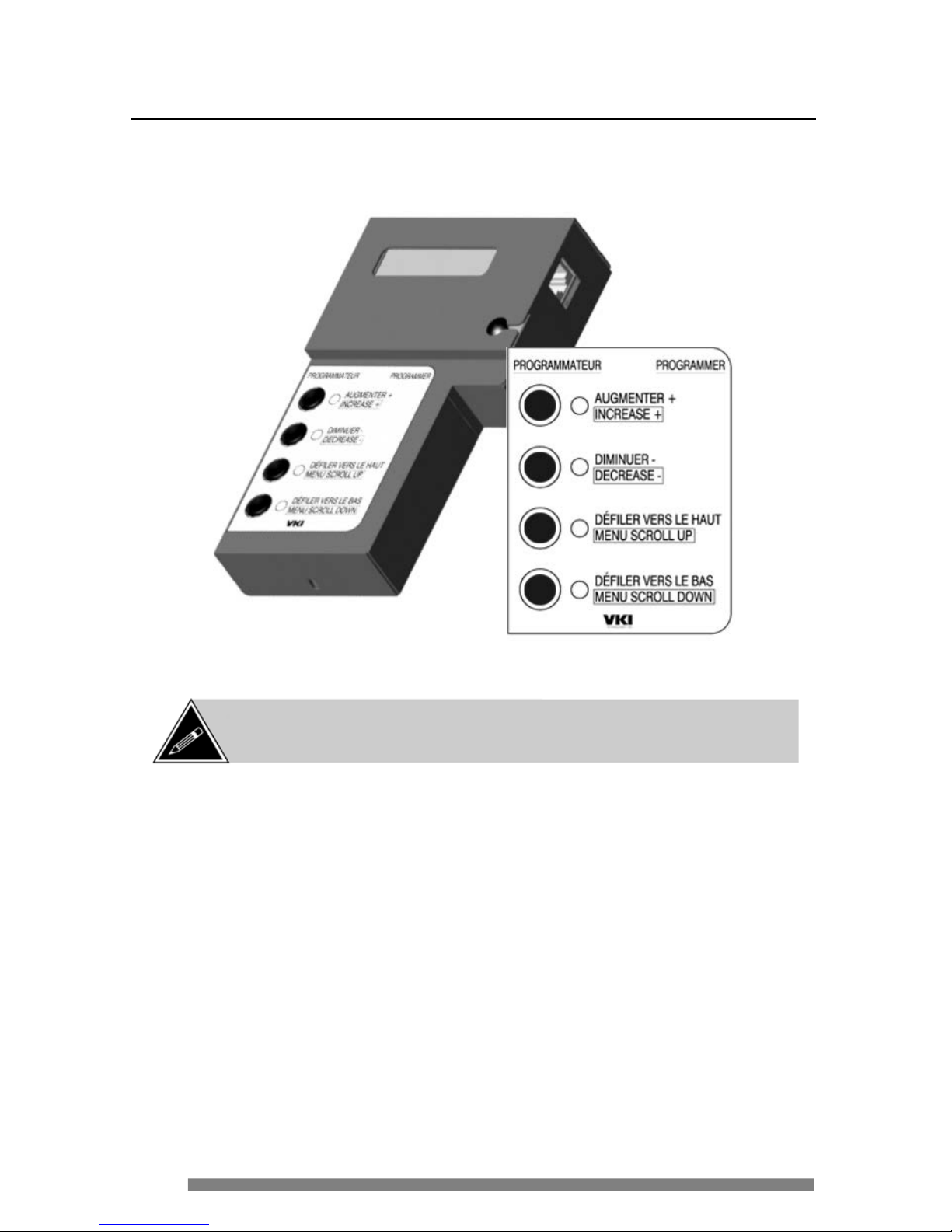
Connecting the Programmer
The ha ndhe ld programmer (sold separately – p/n A210024) acts as an i nterface with
the coffee maker, allowing you to view system errors and allo wing access to th e
softw are featur es incorpor a t e d into the coffee maker .
Espresso Café Handhel d P r ogr ammer
NOTE:
The system status LED’s provide feedback for any minor action
required on the c offee maker. How ever, if the r ed LED is lit, the programmer
must be connected to view the a ctive erro r.
Page 19
19
Connecting the Programmer
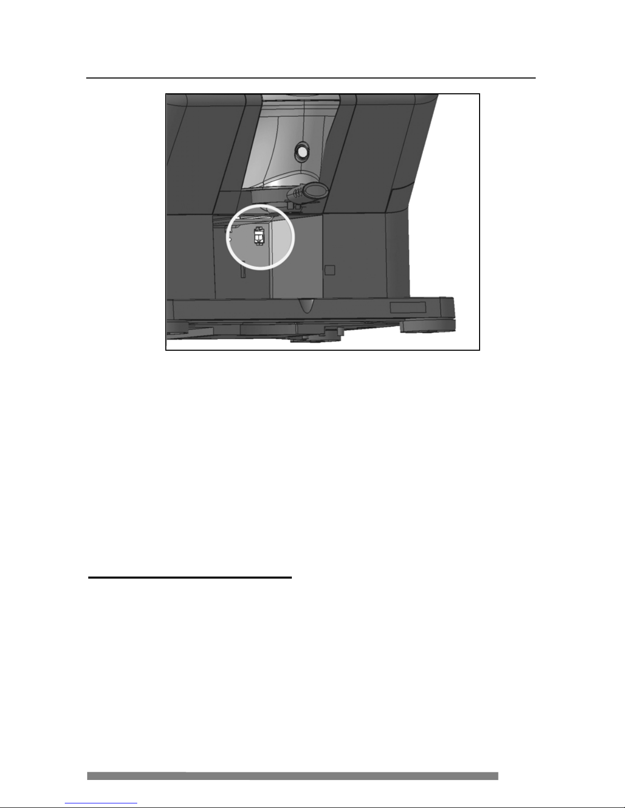
To c onne c t the handheld programmer to the coff ee maker:
1. Swi tch O FF the power to the coffee m aker.
2. Remove the waste bin.
3. Locate the program m er interface por t on the re a r wall of the wa ste bin
area (illustrated above).
4. Connect the phone type ca ble f rom the progr ammer to the interfa c e
port.
5. Swi tch ON the power to the coffee maker.
Power-Up Diagnostic Routine
After the programmer is connected and the coffee make r is powered-up, the
software version is displayed and a diagnostic routine is then initiated to
search for any errors with the equipment. Should a problem be detected, t he
pr ogrammer c a n be used to identif y the problem are a.
More detailed informat ion about error messages, and how to correct them can
be found in the “Troubleshooting” section of this manual (page 64).
Page 20
20
Software Features
Switch OFF the power and connect the handheld programmer to the coffee maker
- use the <
SCRO LL U P> and <SCRO LL DOWN> buttons to navigate through the
software.
Software Menu Navigation
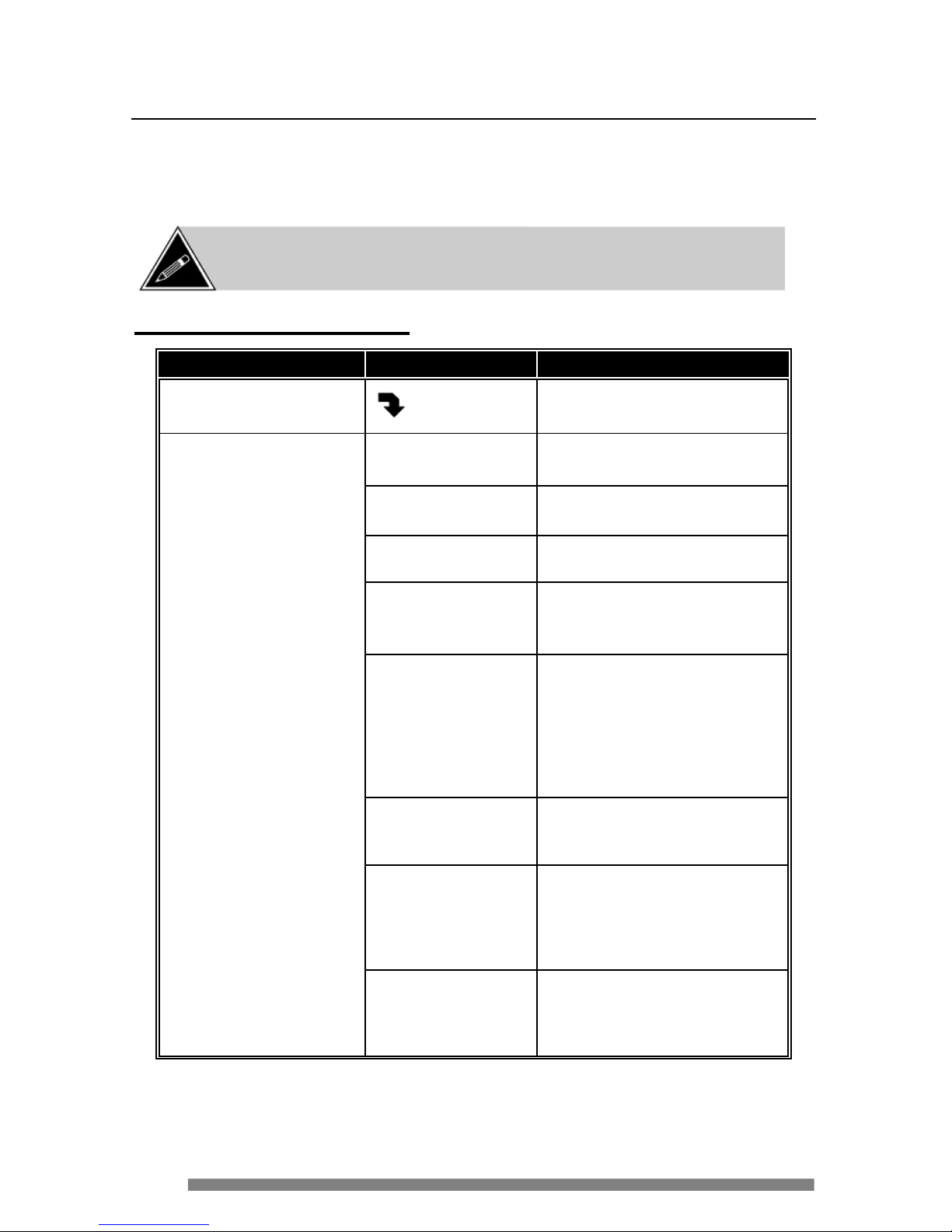
MA IN MEN U
S UB MENU
Procedure
Empt y cycle
Pre ss st art
Press green <START> button to
enter menu.
Empty milk
Press start
Remove milk can ister and press
START to empty the conveyor.
Close milk
Door
The milk door must be closed to
continue this cyc le.
Emptying
Please wait
Wa it until the cycle is comp lete.
rem ove
mil k caniste r
* If the milk can ister has not
been removed, this reminder
appears on the display.
Emp ty water
Press start
Discon nect the water supply
from the coffee maker. When
the “
EMP TY MILK” cy cle i s
complete, this message appears
on the display. At this point,
place the waste bin under the
dispens ing spout.
Emptying
Please wait
Water will be dispensed from
the spout, into the waste bin.
Wa it until the cycle is comp lete.
Instal l drain
insert - star t
Install the drain insert to the
drain plug underneath the coffee
maker. Press START to drain
the remaining water from the
water heater.
Emptying-power
Off when done
Wa it until the cycle is comp lete,
switch the coffee maker power
OFF and disconne ct the service
cord from the power outlet.
NOTE:
Product and w ater settings are calibrated w hen the coffee maker is
manufactured at the factory
. Th e se se tting s cann ot be chan ged (e xcept for settin g
a 6 or 7 fl.oz cup) as no adjustments are required on this equipment.
Page 21
21
Software Features
Software Menu Navigation (continued)
MA IN MEN U
S UB MENU Procedures
Handle position
xxxxxxxxxxx
Once the menu is displayed,
move the selection handle to
each pro duct position to test.
Handle position
Cappuccino
This message is displayed when
the select ion handle is moved to
the Cappuccino position.
Handle position
Espresso
This message is displayed when
the select ion handle is moved to
the Espr esso position.
Handle position
Americano
(hot Water – o n
Professional model)
This message is displayed when
the select ion hand le is moved to
the Americano po sition (Hot
Water on Professional model).
Handle position
Caff e latte
This message is displayed when
the select ion handle is moved to
the Caffè Latte position.
Handle position
Error
An error has been detected with
the position of the handle.
Se ri al nu mbe r
Pre ss st art
Press START to enter menu.
Pnb control
xxxx- xxxx- xx x
The serial number of the control
board is displayed.
Options type 1
xxxx- xxxx- xx x
The serial number of the options
board is displayed.
Se t cu p size
Pre ss st art
Press START to enter menu.
Set cup size
7 oz
Press the “+” or “-” button on the
programmer to set to either 6-oz
or 7-oz cup s ize.
NOTE: Press the “SC ROLL UP ”
or “
SCROLL DOWN” button to
save the changes.
Page 22
22
Software Features
Software Menu Navigation (continued )
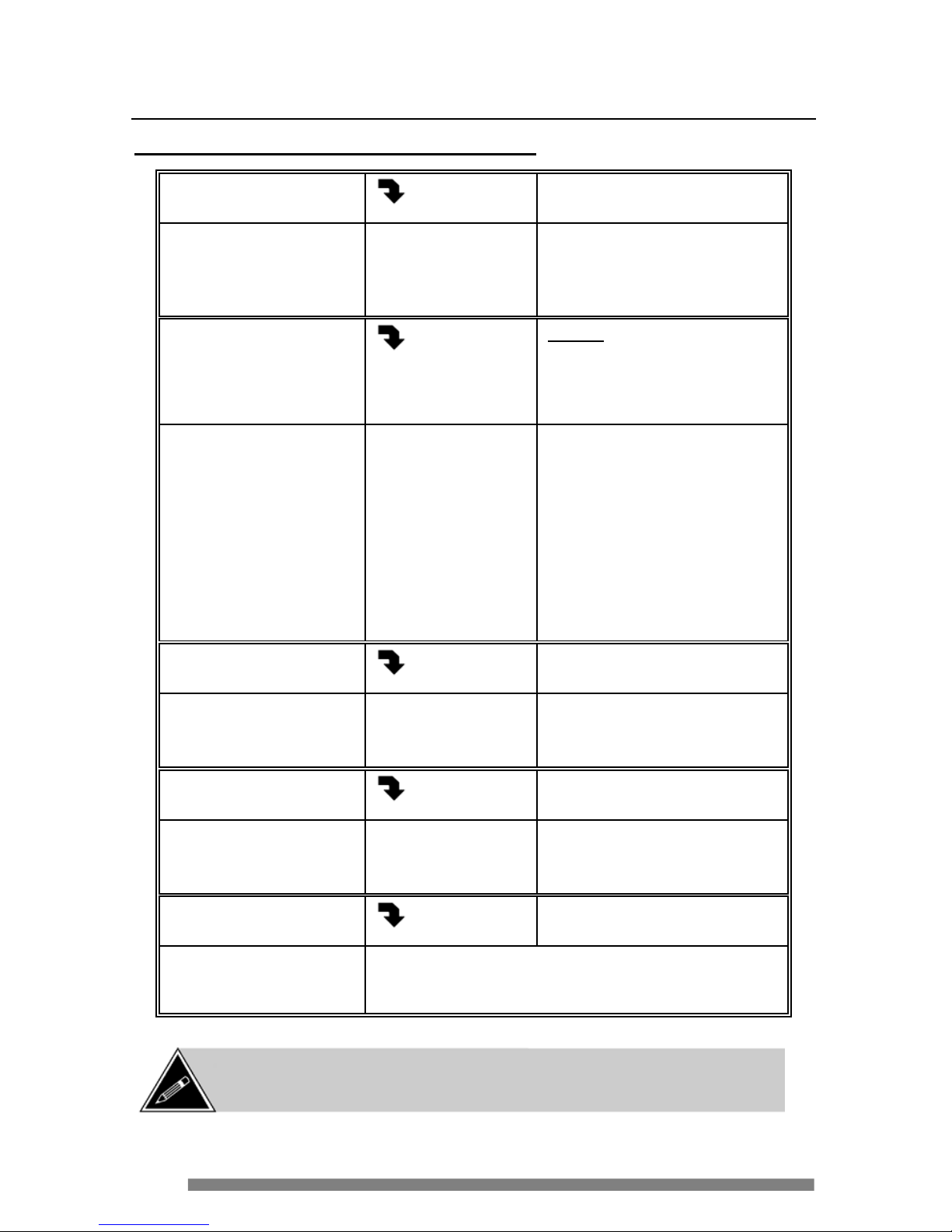
Sele ct reg/pro
Pre ss st art
Press START to enter menu.
Sel ect reg/pro
reg
Press the “+” or “-” button on the
programmer to set to REG
(regular model ) or PRO
(Professiona l model).
Se t hot wate r
Pre ss st art
NOTE: This menu appears
only if the machine is set to
PRO (Professional Model).
Press START to enter menu.
Se T h o t water
press-hold
Press the “+” or “-” button on the
programmer to set quantity of
hot water to be dispensed.
Hot water can be set to “
PRESS
& HOLD” (water is dispensed as
long as the green <
START>
button is pressed) or “by-thecup” in ounces (starting at 1-oz
and incrementing by 0.5-oz to a
maximum of 10-oz).
Drain installed?
Pre ss st art
Press START to enter menu.
Drain installed?
no
Press the “+” or “-” button on the
programmer to toggle between
“
YES” or “NO”.
Pour over mode
Pre ss st art
Press START to enter menu
Pour Over Mode
off
Press the “+” or “-” button on the
programmer to toggle between
“
OFF” or “ON”.
Check for errors
Pre ss st art
Press START to enter menu.
When this feature is activated, the coffee ma ker
performs a quick diagnostic routine. Should any errors
be dete cted, they will be displayed in this menu.
NOTE: Sw itch OFF the pow er to the coffee maker before disconnecting the
programmer.
Page 23

23
Downloading Software Updates
Should a software update be required for the Espresso Café, the update will be
shipped in the form of an EPROM. With the exception of the Espresso Café
downloader, no s pecial tools or change of parts is required to perform the software
upgrade.
To upda te the software in the Espresso C afé:
1. Install the EPRO M with the sof tware up grade into the Espres so Café
programmer.
a) Re move the s crew s at the top and bott om of the housing (figure 1),
then lift and remove the cover.
b) With a f lat screwdriver, gently pry the top and bottom of an existing
EPROM (if installed) and rem ov e it w he n it is loos e .
c) With the notc h on the
EPROM poi ntin g upw ards, line up the two rows
of pins w i th t he tw o rows on the socket, an d slowly inser t the
EPROM
(figure 2). Make cer tain not to bend any of the pins be t ween the
EPROM and t he socket.
d) I nspect the pi ns o n c e more to make cer t ain they ar e all inse rted
prope rly into the socket.
e) Re-ins tal l t he cover onto the programmer.
2. Switch O FF the power t o the machine and remove the waste bi n.
3. Connect the programmer.
4. P ress and h old the <
MENU SC ROLL DOW N> bu t ton (lowe st button) on the
pr ogrammer a nd switch
ON the p ow er to the Espresso Café. Once the
dow nload begins ( L EDs star t to flash), rel ease the button.
5. When the download is complete, switch off the power t o the Espre sso
Café , disconnect the progr a mmer and r eplace the w aste bin.
Remove
Screws
EPROM location
Notch on
EPROM
Figure 1
Figure 2
LCD DISPL AY
Page 24
24
Maintenance
Empty the Waste Bin
The waste bin inside the coffee maker holds approximately 30 used coffee
pods. The system is equipped w ith an optical sensor that detects when the was te
bin is full, and advises you b y li ght ing the yellow “Empty Waste Bin” LED on
the system status indi cator panel .
To e mpty the w a ste bin:
1. G rasp the handle on the front of t he waste bin.
2. Pull the w aste bin out towards you.
3. Discard the content s.
4. If required, use a sponge or absorbent paper towe l to clean a ny liqui ds
from the ar ea beneath where the w aste bin is i nstalled (base).
5. S lide the waste bin back i nt o position.
Cleaning a Milk Overflow
This equipment is equipped with a Milk Overflo w detection system. Should the
w hipper bowl over flow, milk will pour on to t wo overflow contacts and a “Milk
Overflow” error will be displayed on the Programmer.
To clean the milk overfl ow:
1. With the top cover open, clean the milk fro m the whipper bowl, whipper
chamber a nd milk tubi ng.
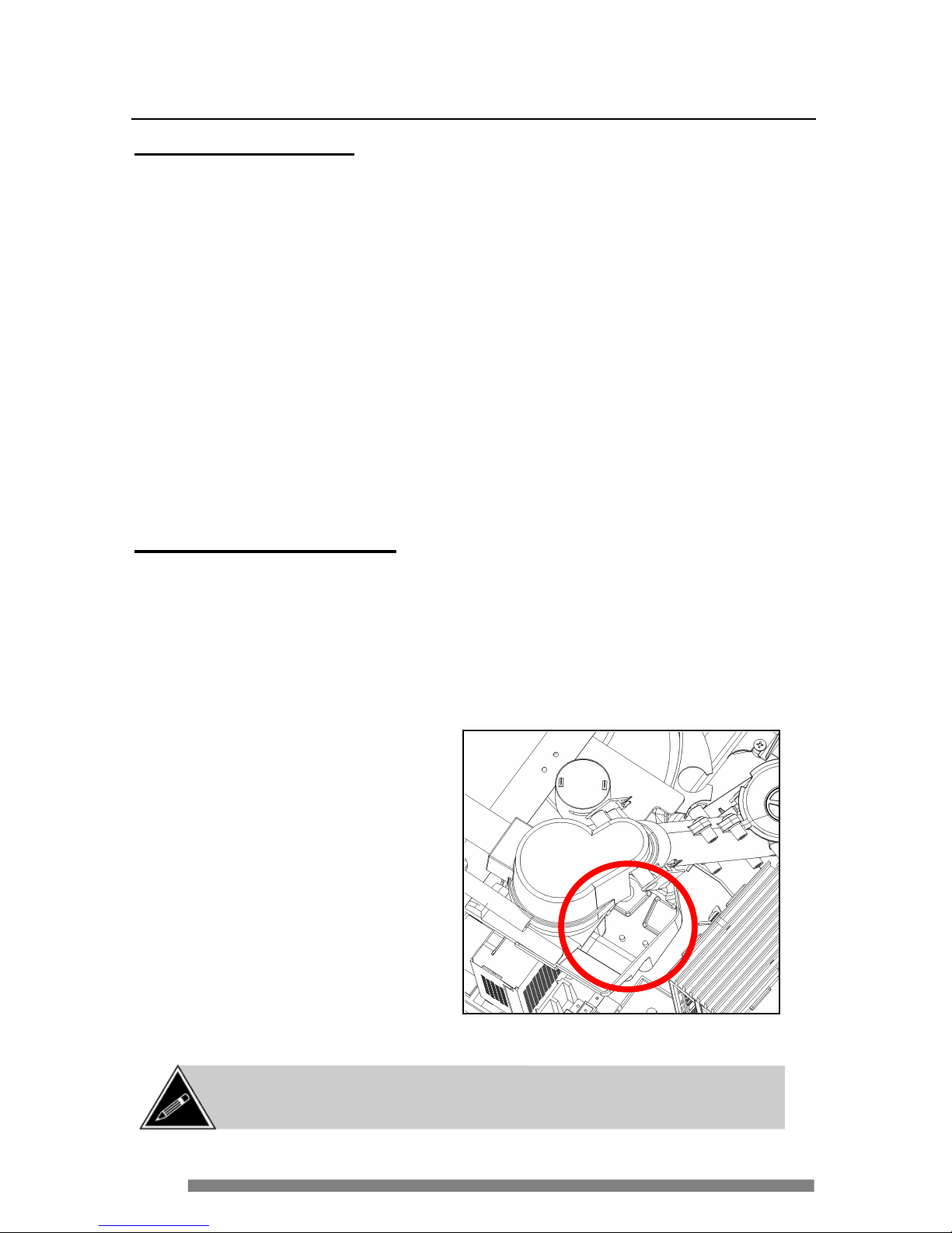
2. Locate the milk overflow
sensors (on the deflector
beneath the whipper bowl)
and clean the overflow by
pouring water directly onto
the deflector and sensors.
If the milk has hardened,
us e a s mall brush to loosen
it. The milk and water will
flow down the deflector
and into the w a ste bin.
3. Once cleaned, cl ose the top
cover.
NOT E: If a Mil k Ov erflow is detected, the red Se rv ice LED w ill ligh t when a
Cappuc cino or Caff è Latte selected. The “ Rinse Cycle”, “ In-Place Cle aning”
and “Empty Cycle ” are also disabled until the m ilk overflow is cleaned.
Page 25
25
Maintenance
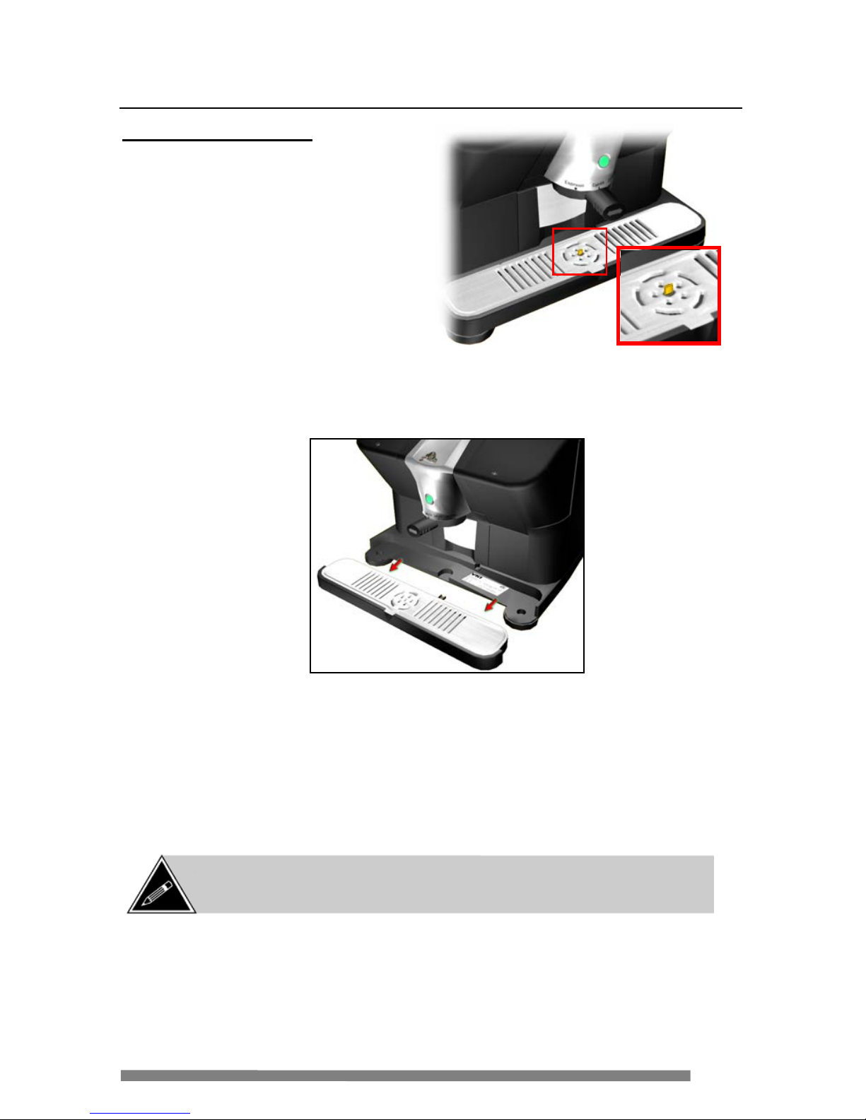
Empty the Drip Tray
The drip tray on the front of the
coffee maker holds approximately
50 0 m l ( 1.7 o z ) of liquid. When too
much liquid has accumulated inside
the tray, a float will rise and
protrude through the drip tray grill.
At this point, the drip tray must be
emptied.
To e mpty the dr ip tra y:
1. Grasp the outer sides of the drip tr ay.
2. Pull the drip tray out tow a rds you.
3. Empty the c ont e nts of the tray, and cl ean it under running wat e r.
4. Remove the waste bin.
5. If required, use a sponge or absorbent paper towe l to clean a ny liqui ds
from the ar ea beneath where the w aste bin is i nstalled (base).
6. Re-install the waste bin and re-i nstall t he drip tra y by sliding it back
into posi t ion until it locks in place.
NOTE: With the drip tray r emoved, t he serial number decal c an be v iew ed.
This decal also shows the electrical specifications of the equipment, as well as
the equipment certification (C SA, UL, etc.).
Page 26

26
Maintenance
Quick-Rinse Cyc le
The rinse cycle must be performed to clean the milk system every time the
customer i s visi te d by servic e or deli very pe rsonnel.
1. With the power to the coffee maker O N, place the selection handle
between
two s elections . The green <START> button LED w ill switch
off.
2. Pull out the w aste bin and place it below the di spensing area.
3. Press and release the green <
START> button to acti vate t he cycle.
4. R epeat the cycle (i f nece ssar y) by pressi ng the green <
START> button
once more.
Forced Quick-Rinse
Should a Cappuccino or Café Latté cycle be interrupted for any reason (loss of
power, error detected, etc) and is not comp leted, the red sys tem s tatus LED w ill
flash. If this occurs, a quick-rinse cycle mus t to be performed to clear it and to
pre vent milk from accumulating in the w hipper a nd milk lines.
NOTE: I f the RED error LED (wrench) is flashing, a quick-rinse cycle m ust be
performed, as this is the only way to clear this erro r.
NOTE: The quick-
rinse cycle can be canceled at any time by
pressing the green <STAR T> button.
NOTE: Do not sw itch OFF the pow er to the coffee maker for at leas t 20
minutes af ter a quick-
rinse is performed. Moisture present inside the coffee
maker after a quick-rinse needs to be vented by the exhaust fan.
Page 27
27
Maintenance
Priming the Water System (on Power-Up)
When servicing the wate r system (or w he n removing an Espre ss o Caf é ), the water
system must first be completely emptied. If not properly emptied, you risk
energizing the heater with no water in the s ystem and damag ing water system
components . Normally, a minimu m of 50 ml (1.7 fl. oz) of water is dispensed
when the Es presso Café is powered-up (possibly more depending on whether the
heater is full or empty). If little or no water is dispensed on power-up, the
water s ystem mus t be pri me d immediately
. To prime the water s yste m,
1. Pull the w aste bin f orward unti l it is directly below t he dispensing spout.
2. Place the sel ection handle in between two sel ections.
3. P ress and h old the green <START> button (it will not be lit at this poi nt )
to start pr iming the wa ter system.
4. Once water starts dispensing, r elease the green <
START> button.
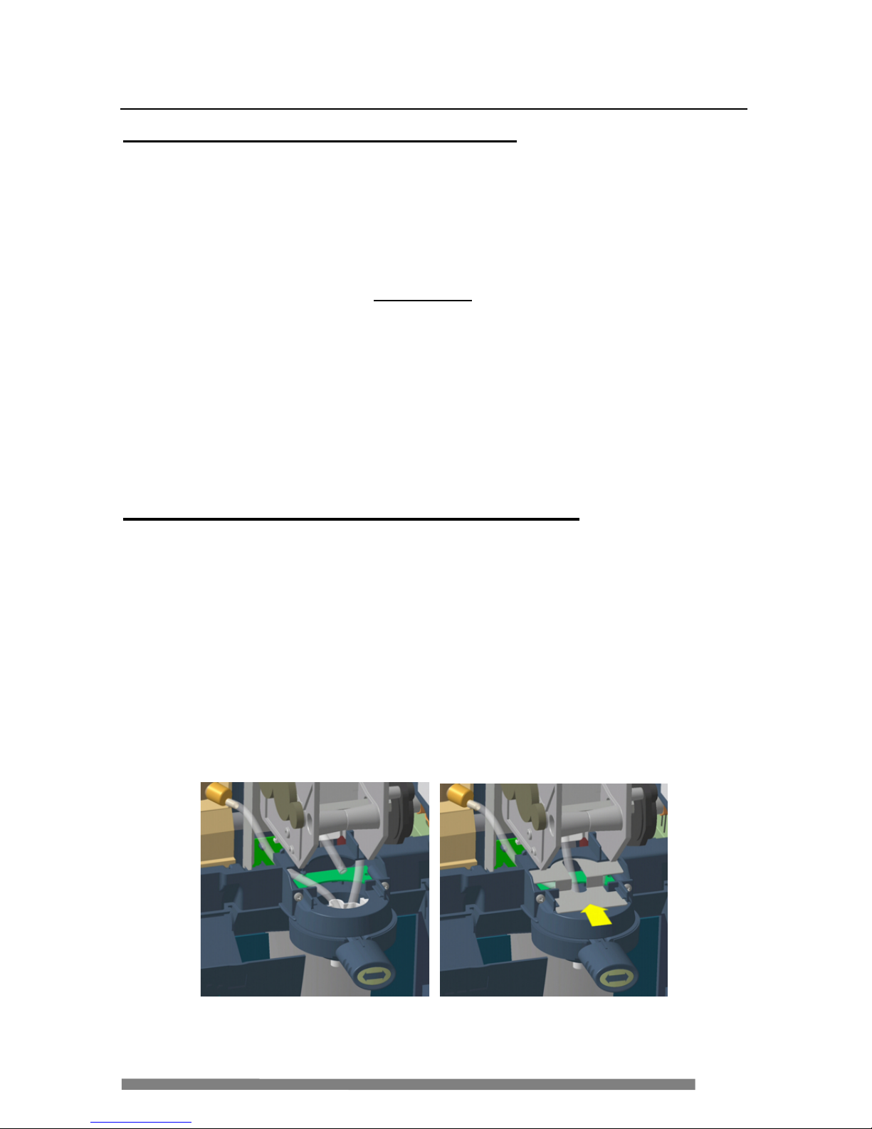
Dispensing Spout and Product Tube Placement
If the dispensing spout is removed, it is imperative that the product tubes be
r e placed in their pr ope r posi t ions. To r emove the spo ut,
1. Sli de the spl a sh guard towards you unt il it comes of f.
2. Lift the t ube s out of the sp out a nd l ift the spout str a ight up.
3. To install the spout, sl ide i t into the selection ring assembly.
4. I nstall the tubes i nto t he spout (milk on left , hot wate r on r ight).
5. Slide the splash guard into the top of the selection ring assembly to
secure the t ubes i n pl ac e.
6. I nstall brewer t ube t hrough the center of the splash guard i nto the spout.
Milk Tube – left side Coffee Tube – center Water Tube – right side
Page 28
28
Using the Cleaning Tab
The cleaning tab performs t wo functions – t h e in-place c leaning/sanit izin g cyc le
(green side of tab) and the emptying of milk from the Espresso Café without the
use of a programmer (red side of tab).
In-Place Cl eaning (Sanitizing Cyc le)
This cycle must be perf ormed as require d by local he a lth authorities and health
regulations.
1. S witch mac hine pow e r off and shut off water by lif t ing the valve handle
on top of the Ever pure QL3 filter head.
2. R emove the E ver pure water filter from the fil ter head (the filter head
must be installe d less than 3 f eet away fr om the i nlet of the machi ne).
a) L ift car tridge slightly and turn completely counter-clockwise.
b) L ower the c artri dge to disen gage it from the head br acket.
3. Fill the Everpure JT San itizing Ca rtridge with SC Johnson J-512
sanitizing sol ut ion ( a va il a ble thr ou gh your loc a l distributor ).
a) U npl ug th e c artridge top on t he Sanitizing Cartridge.
b) Pour sanit izing solutio n i nto the Sanitiz ing C artridge (4 m l of
sanitize r per 1 liter of water ) and r e-install the car t ridge t op o nto
the Sanitizing Cartr idge.
c) Re-install the cartridg e top onto the S anitizin g Car trid ge.
4. I nstall the Sa nitizing Cartridge into the f ilter head.
a) I nser t Sanit izing Cartridge all the w ay into the head bra cket.
b) Turn cartridge c ompletely clockwise until it stops.
5. Turn on the valve at the water fil ter.
6. Swi tch machi ne power ON.
7. I nsert the c leaning tab ( must be inser te d al l the w a y do wn) into the pod
slot with the green
side of the tab facing you.
CAUTION: Th e E sp resso Café must be plumbed-in (“POUR OVER MODE = OFF”
in the set -up) and should be connected to a drain system to perform this cycle.
If a drain is not availabl e, place the waste bin under the dispensing area.
In-Place C le aning (green)
Emptying the Milk (red)
Cle aning Ta b
Page 29

29
Using the Cleaning Tab
In-Place Cl eaning (continued)
8. P osition the selection handle be t ween two sel e c t ions ( t he green light will
switch off).
9. Place the waste bi n under the dispensing area.
10. Press the green <
START> button to a c t ivate the i n-place cleani ng cycle.
a) T he machine will di spense approximat e ly o ne l it e r (34 fl. oz) of
water – this introduces t he sanitiz ing agen t int o the water sy stem.
The yellow status i ndicator LEDs will flash.
b) T he Espresso Café will now pause for approximately t hre e
m inutes . T he wate r w ill heat and the sanitizing a ge nt will start
cleaning the water system . The yellow LEDs will flash.
c) After the th ree minute p ause, t he Espresso Café will dis pe n se a
small amount of water (100-150 ml ) thro ugh ea c h v al v e
(alter nating f rom one to another), t o introduce sanitizi ng agent
thro ugh the product valve s and tubing. The yellow LE Ds will
flash.
d) T he Espresso Café will dis pe nse a sma ll a mount of w at e r (35-60
m l ) throug h e ac h v alve (alterna t ing f rom one t o another). The
yellow LEDs will f las h.
e) When the cycle is complete, the green <
START> button will flash
rapidly, and the yellow L E Ds will f lash.
11. Turn off the w ater at the filter head.
12. Remove the Everpure saniti z ing cartridge and install a new Everpure
water fil ter.
a) Empty the conte nts of the saniti zing car tridge and r inse it w ith
water so that it is ready for us e the nex t time this cycle is
performed.
b) Empty the was t e bi n under the dispensing area, if app lica bl e .
13. Turn on the water at the filter head.
14. Press the green <
START> button (when it lights) to pe rform the purge
phase of t he c leaning process.
CAUTION:
The water bei ng dispensed is extremely hot. Keep clear
of the water flow and use caution when working around the
dispensing area.
Page 30

30
Using the Cleaning Tab
In-Place Cl eaning (continued)
15. The Espr e ss o Caf e wil l now purge t he remaining sanitizing agent by
intr o duc ing fresh w ater i nto t he system. The pu rging cycle dispenses
about 1.8 li t e rs (60 fl. oz) of water.
16. When the gr ee n <
START> button and yellow LEDs fl a sh, empty the
w a ste bin under the dispen sing area, if appl icable.
17. Press the green <
START> button a ga in to per form the final phase of t he
cl eaning process.
18. The Espr e ss o Caf e wil l now rinse the water sys te m by int roduci ng fresh
w a t e r into the syst e m. The rinsing cycle dispen ses about 1.8 l iter s (60 fl .
oz ) of water.
19. Once the purging cycle stops, remove the cleaning tab a nd let the
machine si t for 30 minutes (do not use it dur ing this period). D uring
these 30 minutes, perf orm the following:
a) Em pty the waste bin under the dispens ing area, if applicable.
b) Wipe any liquid spills t hat may hav e occurred during the cycl e ,
including a ny liqui d t hat may have accum ul ated inside the
m achine at the waste bi n area.
c) Fill a c le an spr ay bot tle with a maximum of 2 ml (0.06 fl. oz) of
SC Johnso n J -512 sanitizing so lution per one liter ( 34 fl. oz) of
water.
d) L ight ly spray t he solution t o t he e x t e rior and to the dis pensing
spout s of the E spre sso Café. Do not w ipe away the solution – let it
dry nat urally.
e) Remove the drip tr ay and grill an d rinse both with warm wat e r.
f) Lightl y spray the sani tizing s o luti on onto the dr ip tray & grill,
and the waste bin and allow to dry (do not wi pe aw ay the
solution).
20. After 30 minutes have e lapse d, re-i nstall the drip tr a y a nd grill .
21. The sani tizing cycle is compl ete.
CAUTION: If the In-Pl ace Clea ning/sa nitizing cycle is interrupted and is
not completed, you will be prompted to restart the cycle when the
machine is powered up (a ll 3 yellow LEDs will flash simultaneously).
Page 31

31
Using the Cleaning Tab
Emptying the Milk and Water Using th e Cleaning Tab
This cycle must be perf ormed prior to cleaning the milk conveyor. It is
recommended that a Wet/Dry vacuum cleaner (Shop-Vac type) is available to
completely remove the milk from the c onve yor.
1. R emove the mi lk canister from the m achi ne.
2. I nsert the c leaning tab into the pod sl ot (must be i n serted all t he way
dow n) with t he red
si d e of the tab facing you.
3. P osition the selection handle be t ween two sel e c t ions ( t he green light will
switch off).
4. P ull out the waste bin and pl a c e it below the dispensi ng a rea.
5. Press the green <START> butt on for approximatel y 5 seconds to activate
the cycle.
6. The machi ne will now dispense milk from the milk tube until the
conveyor is empty.
7. O nce the milk system is empty, the cold wa t e r r e servoir wil l al so be
emptied (fr om the water tube at the di spensi ng a rea) .
8. When the cycle is complete, the green <
S TAR T> button will f lash to
i ndi cate that the water heater is ready to be em pti e d.
9. Empty the w a ste bin, an d place the bin on the floor near the rear of the
machine.
10. Conn e c t t he drai n insert to the drai n fitt ing under ne a t h the right rear
corner of the machi ne base. Pl ace the drain insert ho se i nto the waste bin
( whic h should be on the fl oor).
11. Press the green <
START> button to drai n t he water heater.
12. Empty and r e -install t he wa ste bin, and remove the c leaning tab.
13. If a Wet/Dry vac uum is available, insert the vacuum nozzle into t he milk
canister r eceptacle and switch the vacuum on. Leave the nozzle in place
f or several m inutes to re move any r esidua l dehydr a t e d milk from the
system.
CAUTION: T h is pro cedure wi l l em pt y the mi lk fr om t he Espre s so C afe .
If only a cleaning is required, make certain the green side of the cleaning
tab is facing you.
Page 32

32
Cleaning the Milk Conveyor
Open t h e Cover
Opening the cover allows access to the inter ior of the Espresso C a fé.
1. Af te r unplugging the ser vice cord, open the m ilk door and remove the mi lk
canister, then open the water door.
2. O peni n g the doors exposes the screws securing the cover to the coff e e
mak er’ s m ainframe. Remove these two screw s (figure 1).
3. Lift the front of the c ove r until it is comple tely open (figure 2). The hi nge s
at the rear of the cover will keep it open.
WARNING: T he majority of the electrical components in the
Espresso Café are low vo lta ge ( a nd not 120 volts AC) . Never
conn ect t hese elect rical compon ents to 120 volts AC.
WARNING: Drain the water system, switch OFF the power to
the coffee maker, and disconnect the service cord prior to
servicing the equipment.
Figure 1 Figure 2
Page 33
33
Figure 3
Cleaning the Milk Conveyor
The following method can be used only if a Wet/Dry (Shop-Vac t ype) vacuu m is
avail a ble. If one is not avail a ble, proceed to the ne xt section.
Cleaning the Milk Con veyor Using a Wet/Dry Vacuum
1. Fill a clean spray bottle wi th a maximum of 2 ml (0.06 fl. oz) of SC
Johnson J-512 sanitizing solution per one lite r (34 fl. oz) of water. If a
spra y bottl e is not ava il a ble, mix the sani ti z ing solution in a clean le a kpr oof container.
2. With the cover open, re move
the vacuum cap from the top
of t he c onve yor (figur e 3).
3. Libera lly spray (or wipe using
a clean cloth) some of the
sanitizing sol ut ion i nto t he top
of t he c onve yor.
4. S pray (or wipe usi ng a c lean cloth) some sani t izing solut ion di rectly i nt o
the milk cani ster r eceptacle.
5. Let the solution sit for approxi mately five minutes.
6. Af te r the f ive minutes have elapsed, insert the nozzle from the Wet/Dry
vacuum into the milk canister receptacle.
7. S witch on the power to the Wet /Dry vacuum and vacuum the sani tizing
sol ution from the c onve yor for approxi mately tw o minutes.
8. Let the unit sit f or approximate ly 30 minutes for t he saniti zi ng solution to
completely dry insi de t he c onve yor (top c ove r should be left ope n).
9. Af te r 30 minutes have el apsed, re-install the vacuum cap ont o the milk
conveyor.
10. Cl ose the top cover, and re -i nstall the tw o screw s to secure it.
11. Close the water door, insert a milk cani ster and close the milk door.
12. Conn e c t t he service c ord to the w al l outlet.
13. The next time the m achine i s switched on, the conveyor will activate to
prime the system with milk.
NOTE: When c losing the cov er, it may be nec essar y to press dow n slightly
on the lef t and r ight sides of the cov er w hile tightening the scr ew s , otherw ise
the two doors may not close p roperly.
NOTE: The milk system must be purged of all milk product prior to
removing the cover and contour panel.
Page 34

34
Cleaning the Milk Conveyor
I f a Wet/Dry vac uum (Sho p-Vac type) is not availa ble, t he milk conve yor must be
r emoved from the machine for sani t iz ing.
Manual Cleaning of the Milk Conveyor
1. Wi t h the t op c over a lre a dy ope ne d, remove the vacuum cap f rom the top of
the c onveyor (figure 3 on previ ous page).
2. D isconnect the wiring f rom the upper and lower IR (infrar ed) sensors -four
connections (figure 4).
3. O pen the wir ing clip on the right si de of the conveyor and remove the
w i ring ha rness from the c l ip.
4. U sing a Philips scr e wdriver with a long shaft, remove the four scre ws
securing the convey or assembl y t o the base (figure 5).
5. Lift the conve yor assembl y up a few inc he s and c a refully disconnec t t he
pow er wire s and the ground wire from the dispenser motor.
6. Wi t h the conv e yor assembl y out of the cof fee make r, r emove the four
screw s secur ing the motor to t he bott om of the c o nve yor using a Philips
screwdriver.
NOTE: The milk system must be purged of all milk product prior to
removing the cover and/or the contour panel.
Figure 4
Figure 5
Page 35

35
Cleaning the Milk Conveyor
7. Caref ul ly i nsert the screwdriver into the c onve yor through the small grill
wher e the milk cani ster w ould sit (figure 6).
8. P osition the e nd of the screwdrive r a ga inst the a uge r (spir a l) inside the
conveyor to prevent it from turning (f i gure 6a).
9. I nsert a qua rter (coi n) into the coupling at the bottom of the c onve yor.
10. With the screwdr iver j amming the auge r in place, turn the a uge r coupl ing
clockwise
to loosen it. O nc e it is l oose, it ca n be removed by hand by
turning i t clockwise
until it comes off.
11. Once the coupli ng is r emoved, remove the screwdriver from the grill a nd
turn the conveyor a ssembly up side down. The auge r will now slide out of
the c onveyor.
NOTE: There is a s mall O-ring at the bas e of the auger (se e f ig ure
6a). Be v ery c ar ef ul not to lose this O-r ing as it mus t be re-installed
prior to re-assembling the conveyor.
Figure 6
Figure 6a
O-Ring
Page 36

36
Cleaning the Milk Conveyor
12. Fill a clean spray bottle w ith a maximum of 2 ml (0.06 fl. oz) of SC
Johnson J-512 sanitizing solution per one lite r (34 fl. oz) of water. I f a
spra y bottl e is not ava il a ble, mix the sani ti z ing solution in a clean le a kpr oof container.
13. Rinse the auger wi th fresh running w a ter, then spray (or wipe using a cl ean
cloth) the a uge r with sanitizing solution.
14. Ri nse the c onveyor with fresh r u nning wa te r, then spr a y (or wipe using a
clean cloth) the interior of the conveyor with sanitizi ng solution.
15. Set the auger and the conveyor aside until t he y a re completely dry.
16. Once the auge r and conveyor ar e completely dry, mak e certai n the small
O-ring is installed at the bot tom of the a uge r, and a pply some f ood grade
lubr icant to it (and t he surrou nding a rea) .
17. Insert the auger into the convey or, and re -instal l the coupli n g by turning
the c oupli ng counter-clockwise
. The coupling must be hand-tightened
only
– do not use any tools to tighten i t .
18. Install the four screws securing the motor to the bot tom of the c onve yor
usi ng a Philips screwdriver.
19. Re-connect t he wiring to the lower IR sens or boards (blue wires – they
must be routed be hind the conveyor) and t he power wires and ground wire
to the dispenser motor.
20. Install the conveyor assembl y on to t he base of the machine with four
screws.
21. Reconnect the wiring to the upper IR sensor boards (red wires – they must
be routed in front of the conve yor).
22. Insert the wiring harness into the c li p on the right side of the co nve yor, and
cl ose the cl ip to secure the harness.
23. Re-install the vacuum cap onto t he t op of the conveyor.
24. Cl ose the top cover, and re -i nstall the tw o screw s to secure it.
25. Cl ose the water d oor.
26. Insert a m i lk canister and close the milk door .
27. Conn e c t t he service c ord to the wall outlet.
28. The next time the m achine i s switched on, the convey or will activate to
prime the system with milk.
NOTE: When c losing the cov er, it may be nec essary to press dow n slightly
on the lef t and r ight sides of the cov er w hile tightening the scr ew s , otherw ise
the two doors may not close p roperly.
Page 37

37
Removing the Coffee Maker
Should the coffee ma ker need to be relocated or removed for any reason, the milk
sys tem and the water system must
be purged (emptied) beforehand. This is
especia lly im portant if the coffee ma ker i s to be transpor te d t o a nother location.
Empty the Milk Conveyor
1. Switch OFF the po wer to the coffee maker.
2. R emove the mi lk canister.
3. Remove the waste bi n.
4. Con ne c t t he programmer to the coffee maker (see “Connecting the
Programmer” section).
5. S witch the power ON .
6. Sc roll to the “
EMPTY CYCLE” menu and pr e ss <START>. Th e top l ine of
the display now r e a ds “
EMPTY MILK”.
7. Place the w aste bin at the dispensing spout a rea.
8. Press <
START> to activate the cycl e. The message on t he display now
reads “
EMPTYING – PLEASE WAIT”.
9. Once compl ete, the coffee mak er will automati cally proceed to the
“
EMPTY WATER” menu.
10. Using a Shop-Vac type vacuum, pl ace the vacuum nozzle dir ectly over
the mi lk canister receptacle (the grill onto whi c h the milk canister lid
check valve engages).
11. Switch
ON t he va c uum and a llow a pproxim a t e ly one minute fo r the
vacuum to pul l any r ema ining milk from the c onve yor sy stem.
NOTE: As a saf ety precaution, the milk door must remain closed
throughout the entire procedure. If the door is opened, the auger w ill
stop.
NOTE: The next time the milk canister is re-inserted (after running the
“EMPTY MILK” cycle), dispense two cups of Caffè Latte or Cappuccino to
completely refill the conveyor.
WARNING: Do n ot ins t a l l t he dr ai n inse r t into the dr ai n fi tt i ng du r ing
the “
empty milk
” cycle.
Page 38

38
Removing the Coffee Maker
Drain the Water (Reservoir and Heater)
If continuing from the “EM PTY THE MILK CON VEYOR” section on the previous page,
proceed directly to step #4.
1. Dis connect the water source (if applicable).
2. Wi th t he power OFF , remove the w aste bin a nd c onnect the programmer to
the cof fee mak er and switch the p ow er ON.
3. Scroll to the “
EMPTY CYCLE” menu and pr ess <START>. Scroll again until
the display r e ads “
EMPTY WATE R – PRESS START ”.
4. Place the waste bin below the dispe nsing s pout .
5. Press <
START> t o activate the cycle. The messa ge on t he display n ow read s
“
EMPTYING – PLEASE WAIT”.
6. When reservoir is empty, the display will read “
INSTAL L DRAIN INSERT –
STA RT”. Install the drain insert into the drain fitting underneath the base.
a) C arefull y po sition the coffe e mak er so that only the r ight rear leveler
is ‘hanging’ from the end of the counter top.
b) Locate the drain fitting beside the right rear leveler a nd pl ace the
was te bi n directly under it.
c) While pressing the lock latch, install the drain insert into the fitting
an d lock it i n pl ace by releasing t he loc k l atch.
7. Pr ess th e <
START> button to acti vate the dr ain cy cle. Water will now start
dr a ini ng from the inse rt.
8. The display now read s “
emptying – power off when done”. Once the water
i s emptied, switch of f the power t o the coffee maker.
9. R emove the drain insert and dis con nect t he service cord f rom t he w all ou tlet.
Page 39

39
Removing the Coffee Maker
Storing the Coffee Maker
Should the coffee make r need to be stored indefin it ely, or if it will not be us ed for a
week o r more, precaut ion s must be taken to prevent damage to internal compo nents
of t he e quipment.
To properly store the coffee maker, perform these simple procedures and the
equipment will be r eady to use when it is to be installed at a c ustomer l oc a tion.
1. R emove the mi lk canister.
2. Empty the milk c onve yor (see page 37 for detai led instruct ions) .
3. Drain the water fr om the reservoi r and heater (see page 38 for detail ed
instructions).
4. U sing a Shop-Vac type vacuum , place the vacuum nozzle di rectly over
the mi lk canister receptacle (the grill ont o whic h th e milk canister lid
chec k valve enga ge s). It is not nec essary t o o pe n the top cover of t he
coffee ma ker – only the milk door.
5. Switch
ON t he va c uum and a llow a pproxim a t e ly one minute fo r the
vacuum to pul l any r ema ining de hydrated milk from the con ve yor
system.
6. Empty and clean t he waste bin.
7. Empty and clean t he drip tra y.
WARNING: If all t he dehydrated m i lk is not remove d from t he coffee
maker prio r to storage or a pr o lo nge d period of no n-use, it will harden
and dama g e t h e mil k co nv eyo r a nd whi pp er.
NOTE: Milk can also ac cumulate ins ide the unit and should be c leaned us ing a
Shop-
Vac type vacuum . This requires removal of the top cover and contour panel
and can be done befo re storing the unit (r ecommended), or before installing it.
Page 40

40
General Information
• Most of the electrical components in the Espresso Café are low vol tage
(and not
120 volts AC ). Never connect the se electri cal components to 120
volts AC .
• When the Espresso Caf é i s powered up, a small quantity of water will be
dispensed from the spout. This is a normal as air i s being purged from the
water system.
• The water system is pressurized and it is equi pped with a pressure rele ase
f itting. Should the pr e ssure e xceed 185 psi, the fitting will automatically
open to rel ease the excess pressure.
• Drain the water from the c offee maker bef ore replac ing any
component in the w at er lin e or a c o n trol board.
• I t is not nece ssar y to insta ll a backflow prevention system as one is already
incorporated in the inlet valve.
• When inst a ll ing the fittings i nside the coffee maker, t he y should be ha nd-
tightened, and then tighte n e d a n a ddi tional ¼ turn w ith a wrench. If a
f itting i s leaking, ti ght e n the fit ting i n ¼ t urn intervals until the leaking
stops.
• The milk canister sys te m uses sensor s to dete c t when the product level runs
l ow. These sam e sensors are use d to prime the system once a new milk
canister is installed.
o When the milk canister is initially installed, or when replaced, the milk
dispenser motor may automatically activate to prime the milk through the
system. Once primed, the dispenser motor will stop automatically.
o When the milk canister empty, any selections requiring milk are disabled and
the green START button will not illuminate.
• If the cover of the c offee make r is open i n a ver y brightly l it room ( for
testing pur poses), the optical sensors may gi ve in a c c urate r e adings. If t his
i s the case, te st the coffee maker with the cover closed.
• To simplify moving the coffee make r, only the fr ont levelers are equipped
w ith non-sk id pads. Simply li ft the f ront of the coffee ma ker, and slide it
w here requir e d. When the front is place d ba c k onto the countert op, the
non-sk id l evelers prevent the unit from sliding.
• All the w i ring in t he coffee ma ke r is labeled point-to-point to identi fy the
component(s) on which they a re connected.
• When the wate r heater is first use d, a slight odor may be detected. This is
nor mal and the odor w i ll qui ckly dissi pa t e .
Page 41

41
Replacing Major Components
Opening t h e Cover
Opening the cover allows access to the interior of the Espresso Café. Some
ma intenance or s ervice can be performed with the cover open, but in other cases the
cover needs to be removed completely (see “Removing the Cover and Contour
Panel” on page 42).
1. After unpl ugging the service cord, open the milk door and remove the mi lk
canister, then open the water door.
2. O pening the doors exposes the screws securing the cover to the coffee
maker’s mainfra me. Remove these two screws (figu re 1).
3. Lift the front of the c ove r until it is comple tely open (figur e 2). The hi nge s
at the rear of the cover will keep it open.
WARNING: Switch OFF the power to the coffee maker,
disconnect the service c or d a nd dr a in the w a t e r s yst e m pr ior
to servicing the equipment.
NOTE: When c losing the cov er, it may be nec essary to press dow n slightly
on the lef t and r ight sides of the cov er w hile tightening the screws, otherwise
the two doors may not close p roperly.
WARNING: T he majority of the electrical components in the
Espresso Café are low vo ltage (and not 120 volts AC) . Never
conn ect t hese elect rical compon ents to 120 volts AC.
Figure 1 Figure 2
Page 42

42
Replacing Major Components
Rem oving the Cov er and Contour Panel
For many repair procedures, removing the cover provides suffic ient acces s to coffee
maker components. For greater access to components, the contour panel can also be
removed.
Removing the Cover
1. Af te r unplugging the ser vice cord, ope n t he milk door a nd remove the
mi lk canister, then open the water door.
2. O peni n g the doors exposes the screws securing the cover to the coff e e
mak er’ s m ainframe. Remove these two screw s.
3. Lift the front of the c ove r until it is comple tely open. The hinges at the
rear of the cover will keep i t open.
4. Disconnec t t he wiring ha rness from the <
START> but ton boa rd and t he
System S tatus LE D panel. Disconne ct the inline connec tor for the milk
door IR sensor .
5. Remove the wiring from the routi ng c lips built i nt o the unde rside of the
cover.
6. P ull the cove r forw a rd then lif t it u pwards to remove it from the quick-
release hi nges.
NOTE: When c losing the cov er, it may be nec essary to press dow n slightly
on the lef t and r ight sides of the cov er w hile tightening the scr ew s , otherw ise
the two doors may not close p roperly.
Page 43

43
Replacing Major Components
Removing the Contour P a nel
7. Remove the drip tray and r ot a te t he coffee ma ker 90 degrees.
8. From the rear of the coffee ma ker, remove the two screws located at the
exterior bottom of the c on tour panel.
9. Remove the screw above t he bridge mount at the inter ior top of the
contour pane l (inside ce nt e r of pane l).
10. Rem ove the two screws securing the contour pa ne l to the mainfr ame.
These screws are located at the outer side of both fli p door areas.
11. Slide the contour panel towar ds the rear unt il it is fr e e from the
mainfra me.
NOTE: The two doors are simply snapped into place on the mainf r ame. No
tools are required to install replacement doors.
Page 44

44
Replacing Major Components
Brewer
With the cover already open:
1. Disconnect the wir ing har ne ss connector from the bre wer cir c u it boar d.
2. Disconnect the brewer motor harness.
a) Open the t wo cli ps securing the ha rness to the s upport a nd remove
the brewer w iring.
3. R emove the screw securing the left side of the brewer to the mainframe.
4. Lift the front of the brewe r and pu ll t he brewer str a ight up and out (note
that the right side of the br e wer is secur e d to t he mai nframe by snap clip).
5. I nsert the new brewer assembly making sur e t he right side snaps i nto t he
mainfra me. Secure the l eft si de to the m ainfram e with a screw.
6. R econnect all wiring harnesses.
Brewer Heads
Wi t h the b rewer in the open position:
1. Grasp the front and rear of the inlet or outlet
head.
2. P ull the hea d straight up and out of the brewer.
3. Dis connect the tubing on the inlet head
by opening the plastic clip and pulling
of f the tubing.
4. Prior to re-installing the brewer head
assemblies, insert the brew hose into
the pour s pout.
5. Align and push the brewer heads into
position.
NOTE: Fro m this point forward, it is assumed the coffee maker cover and/or
contour panel is removed for servicing and pow
er is OFF. Once service is
complete, re-install the coffee maker cover and contour panel.
Page 45

45
TORX
Screws
Screws
Replacing Major Components
Brewer Motor
1. Disconnect the brewer wiring
harnesses and remove the brew er.
2. Remove the three la rge
TO RX screws
securing the motor to the brewer
assembly.
3. P ull the motor straight out.
4. Secure the new brewer motor to the
brewer assembly with the three
TO RX
screws.
5. Re-install the brew e r and reconnect the brewer wiring harnesse s.
Sel ection Ring & Board
1. Wi t h the cover open, remove the spi ll pla t e a nd spout.
2. Remove the two screws from the
retainer securing the s election ring
to the mainfra me.
3. Remove the retainer, and pull out
the selection ring.
4. Dis connect the wiring harness from
the rear of the s election board and
pull the board out to re move it.
5. Slide the new sel e c t ion boar d into position.
6. In s ta ll th e selection ring and secure it to the mainframe by screwing the
retainer in place.
7. Connect the wiring har ne ss t o t he rear of the selection board.
8. I nstall the spout a nd t he spill plate.
Page 46

46
Replacing Major Components
Wa ter Heater
1. Drain the water from the coffee maker (see page 38).
2. Disconnect the two el ement wires at the bottom of the heater.
3. D isconnect the ground wir e at the side of the hea t e r.
4. Remove the thermal cut-off switch assembly by removing t he t wo hex nuts
securing the retai ning bracket to the heater as sembly.
5. D isconnect the lar ge inl e t fitting at the bot tom side of the hea ter.
6. D isconnect the outl e t fit ting at the top side of the heater.
7. Remove the two hex nuts on top of the heater securi n g it to the heater
support. The tempera ture probe c an now a lso be removed.
8. Pull the hea te r towa rds the r ear a n d the n t o the side to remove it.
9. Re-i nstall the new heater (making sure the t e mpera t ure probe is also
installed on top of the he a te r) and connect all the w ater fittings.
10. Re-install the thermal cut-off switch assembly.
11. Reconnect the red & black wir e pair to the the rmal cutoff switch (if they
were disconnec ted).
12. Reconnect the white & bl ack wire pair to the heater assembl y termi nals
identifie d by the plastic red
collars (diagonally). Do not connect the
wiring to the ter minals with the white collars .
NOTE: If dis connecting the ther mal cut-off sw itch w ires , hold on to
the body of the switch to relieve any excess pressure that may
damage it when the wires are pulled.
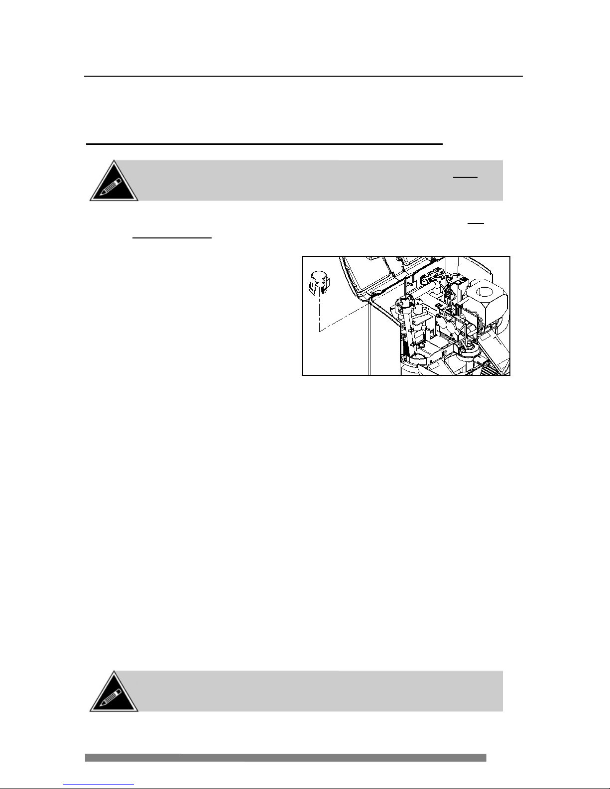
WARNING: Use caution when servicing the water h eater as it may be
ex tremely hot and can cau se sev ere bur ns.
NOTE: When any component of the water system is replaced, a quick-rinse
cycle must be perfo rmed to purge air out of the sy stem.
Red
Collars
Page 47

47
Fla t side up
Replacing Major Components
Temperature Probe
1. Disconnect the inline
connector on the temperature
probe wiring har ne ss.
2. Loos en the hex nuts securing
the top of the heater to the
heat e r su pport.
3. Remove the old temperature
probe.
4. Slide the ring terminal of the new temperature probe (the flat side must be
up) ove r the thr e aded stud ne xt to the out let of t he heater.
5. Place the ceramic washer over the temperature probe ring terminal.
6. I nstall the heate r sup port over t he two thre a de d stud s on top of the heater.
The te mpera t ure probe ring terminal a nd flat wa sher must be between the top
of the heater and the heate r sup port.
7. Tighten the two hex nuts securing the top of the he a t e r to the heate r supp ort.
8. Reconne ct the inline connec to r on the tempera t ure probe wiring harne ss.
Th erma l Cut-Off Switch
1. Disconnect the two wires from the therm al cut-off switch.
2. Remove the thermal cut-off switch
assembly by removing the two hex nuts
securing the retaining bracket to the
heater assembly.
3. Install the n ew therma l cut-off sw itch and
secure it in place by installing the
r e t a ini ng bracket with two hex nuts.
4. Reconnect the two wires to the thermal
cut-off switch.
NOTE: When disc onnec ting the thermal c ut-off switch wires, hold
on to the body of the switch to relieve any excess pressure that may
damage it when the wires are pulled.
WARNING: Use caution when servicing the water h eater as it may be
ex tremely hot and can cau se sev ere bur ns.
Page 48

48
Replacing Major Components
Wa ter Reservoir
1. Drain the water from the coffee ma ker (see page 38).
2. R emove the inlet tubing connected on the bre wer side of the reservoir.
3. Remove the outlet tubing con n e c te d to the bottom of the re servoir.
4. Disconnect the float switch w iring (inline c onne c t or).
5. Remove the lar ge screw securing the front of the re servoir to the suppor t.
6. R emove the other large screw securing the side of the reservoi r to the
support.
7. R emove the water reservoir .
8. Install the new reservoi r and secure i t in place wi th the two screws.
9. Reconnect the inlet tubing on the brewe r si de of the r e servoir .
10. Reconnect the outl e t tubing to the bottom of the reservoir.
11. Install a ne w rubber gasket to the top of the reservoir.
NOTE: When any component of the water system is replaced, a quick-rinse
cycle must be perfo rmed to purge air out of the sy stem.
Page 49

49
Replacing Major Components
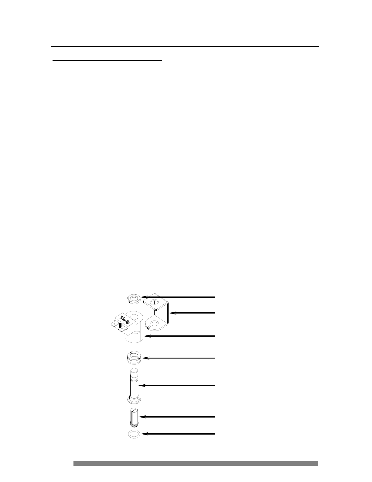
Water Level Float Switch
1. Loosen and remove the plastic hex nut securing the switch to the reservoir
– l oc ated at t he outside bottom of t he reservoir.
2. U sing wir e c ut ters, cut the t wo float switch w i res at the inli n e c onne c t or
and discard the c onnector .
3. F rom the inside of the re servoir, pull the switch str a ight out.
4. Remove the o-ring installed between the float switch and the water
reservoir. The o-ring may be stuck the bottom of t he float switch or i t may
have fal len into the water reservoir.
5. P a ss t he wiring from the new swit c h from t he inside of the reservoir t o th e
outsid e (so i t is com ing out the bottom) .
6. After making sur e the o-ring i s installed on the bot tom of the float switch,
secure the sw itch into the bot tom of t he reservoir w ith the plastic hex nut.
Hand-tighten only as over-tightening will str ip the thre ads.
7. I nsert the wiring terminals into t he c onnector provided.
8. Reconne ct the inline connec to r.
NOTE: Insert the w ires into the connector only after they have
been passed through the bottom of the reservoir.
NOTE: Once the float switch wire s are cut from the connector, the
switch can no longer be used and must be replaced with a new one.
Install the connector only
after the float is installed
inside the reservoir.
Page 50

50
Replacing Major Components
Inlet Va lve
1. Drain the water from the coffee ma ker (see page 38).
2. D isconnect the inl e t fitt ing from the valve.
3. Disconnect the two w ires from each coil (f our wires total ).
4. D isconnect the tubi ng from the i n let valve.
5. Lift the v a lve stra ight up and out.
6. I nstall the new valve by slidi ng it dow n int o the channel at the rear of the
base.
7. Connect the t ubin g to t he inl e t val ve.
8. Connect the wiring to the inlet va lve (the tw o longer wires connec t to the
rear coil of the val ve) .
NOTE: The inlet valve is equipped w ith a built-in backflow prevention
system as well as a flow regulator.
NOTE: When any component of the water system is replaced, a quick-rinse
cycle must be perfo rmed to purge air out of the sy stem.
Page 51

51
Replacing Major Components
Outlet Valves
1. Drain the water from the coffee ma ker (see page 38).
2. Disconnect the wiring from each valve coil (three pairs of wires).
3. D isconnect the tubi ng from the outlets of the hot water and m ilk valves.
4. Remove the c offee tubing at the brewer head by opening the plastic clip.
5. Disconnect the large fitting from the heater assembly.
6. Lift the v a lve assembly up and out.
7. Place the new outlet valve assembly in position.
8. Connect the lar ge fi tt ing to the hea te r assembl y.
9. Connect the t ubin g going to the whipper bow l.
10. Conn e c t t he c offee tub ing (pa rt of the outlet valve assembly) to the brewer
head and secure it in pl ace wi th the plastic clip.
11. Connec t t he wiring to e a c h of the valve coil s (thr e e p ai rs of c olor coded
wires).
White Wires
Blue Wires
R ed Wires
Milk Valve
Water V alv e
Coffee Valv e
NOTE: The out let valv es ar e available only as an assembly ( three v alv es
with fittings installed). Individual valves are not available.
WARNING: Use caution wh en servicing the outlet valv es as they may
be extremely hot and can cause seve re burns. The water system must
be drained before servicing this component.
NOTE: When any component of the water system is replaced, a quick-rinse
cycle must be perfo rmed to purge air out of the sy stem.
Page 52
52
Replacing Major Components
Rebuilding an Outlet Valve
This procedure outlines the steps involved in disassembling, rebuilding and
reass embling a Snap-Tite outlet valve. Required materia ls are a 3/8” socket wrench,
a 3/8” drive torque ratchet, and a special Snap-Tite flange socket tool for 3/8”
flanges (VKI p /n – 100431-001). Th is procedure can be performed with the valve
assembly installed in the coffee m aker.
1. With the unit drained of all water and the cover removed, disconnect the wires from
the outlet valve.
2. Using a 3/8” socket wrench, remove the coil nut. Lift the coil and strap above the
plunger housing.
3. Using the special Snap-Tite flange socket, loosen and remove the flange nut.
4. Slowly lift and remove the plunger housing.
5. Inspect the orifice in the valve body to ensure it is free of nicks, scratches and
debris. Remove any debris by blowing it out.
6. Remove the old o-ring and replace it with a new one. Be sure that the o-ring is
seated properly for re-assembly.
7. Install a new plunger assembly and re-install the plunger housing.
8. Re-screw the flange nut on the plunger housing, first by hand and then tighten
using a 3/8” drive torque ratchet set to 35-45 inc h pounds of torque.
9. Replace the coil and strap over the plunger housing.
10. Install the coil nut onto the plunger housing, then tighten using 3/8” drive torque
ratchet set to 15-25 inch pounds.
11. Reconnect the wires, replace the cover and contour panel, and switch ON the coffee
maker to test for proper operation.
Coil Nut
Strap
Coil
Fla nge Nut
Pl unger Housing
Pl unger Asse m bly
O-Ring
Page 53

53
Options
Board
Control
Board
Replacing Major Components
Control Board & Options Board
1. D isconne ct all of th e w iring harne ss co nnectors a t the r ear of the ci rcuit boards
and disconnect the two ground w ires co nne c ted t o the termina ls on the heat
sink.
2. S li de the board assembl y about one inch towards the rear of the unit, and lift it
out of the ba se.
3. S e pa rate the con trol board from the options board.
a) Grasp each board from the bottom (the
side without the heat sink).
b) Carefully, pull the two boards apart,
hol ding th em as str a igh t a s po ssi bl e .
4. Connect a contr ol board to an option s board.
a) A lig n t he 48 p ins on the opt ions board
wit h th e 48 p in connector on the control
board.
b) Gently press the two boards together
u ntil t he clips on the control board lock
i nto the cutouts on the options board.
5. Insert t he b oar d a ssembly (w i th hea t si nk up) i nt o the ba se an d sl i de i t abo ut
one inch towards t he front of the u nit, unti l i t locks in pla ce.
6. C on nec t t he gr o und wi r es to th e ter m i nal s o n t he he a t si nk .
7. Connect all t he remaining wiring harnesses to the circui t board s.
Caution: If possible, drain the water from the coffee maker before
replacing this component. If it is not drained, 420ml (14 oz.) of potentially
hot wa ter will be disp en sed a t the spo ut aft er a contr ol boa rd is replac ed.
Page 54

54
Replacing Major Components
Water Pump Assembly
The followi ng procedur e de scribes how to repl a c e the water pump. Should the
pump har ne ss /diode-bridge need replaci ng, proceed to the ne xt page.
1. Drain the water from the coffee ma ker (see page 38).
2. Remove the water t ube c onnected to the f ront of the water pump (coming
from the flow meter).
3. Remove the plasti c tube g oing from the pump to the water heater fi tt ing.
4. D isconnect the water pump harness from the options circuit board
(connector i s la beled as “AC OU T 2 – J25” on the options board).
5. Disconnect the wat e r pump harness gr ound from the hea t sink on the
control circuit boar d.
6. Remove the pump wiring harness/diode-bridge from the coff ee maker.
S ome of the c lips securing the harnessi ng throughout the coff e e make r
need t o be opened to f ree the pump harne ss.
7. Remove the two scr e ws secur ing the water pump supports to the base.
8. Remove the old w a te r pump.
9. P lace the ne w wate r pump i nto po sition and scr e w the supports into the
base.
10. Rout e t he ne w harne ss from the options circui t boa rd to the pump making
sure to c lose t h e wiring clips to secure it i n place.
11. Connec t t he water pump harne ss to the options circuit boar d (connector is
l abeled as “A C OUT 2 – J25” on the options board).
12. Connec t t he water pump harne ss ground to the heat sink on the control
ci rcuit board.
13. Reconnect the plas tic tube from the pump to the water heater fitting.
14. Reconnect the water tube from the fl ow meter.
NOTE: When any component of the water system is replaced, a quick-rinse
cycle must be perfo rmed to purge air out of the sy stem.
Caution: Drain t he water fr om the coffee m aker bef ore servicing this
component.
Page 55

55
Replacing Major Components
Water Pump Harness/Diode-Bridge Assem bly
The following procedure describes how to replace the water pu mp harness/diode
bridge assembly should it need replacing. Should the water pump need replacing,
instruc tion s are provided on the previ ous page.
1. R emove the screw in the center of the el ectri cal connector ( diode-bridge)
on the top of the water pump.
2. Remove the c onne c t or (diode-bridge) from the top of the water pump.
3. D isconnect the water pump harness from the options circuit board
(connector i s la beled as “AC OU T 2 – J25” on the options board).
4. D isconnect the water pump harness ground from the hea t sink on the
control circuit boar d.
5. Remove the pump wiring harness/diode-br idge f rom the coffee maker.
S ome of the c lips securing the harnessi ng throughout the coff ee maker
need t o be opened to f ree the pump harne ss.
6. Route the ne w har ne ss from the options ci rcui t bo a rd to the pump making
sure to cl ose the w iring cli ps to secure it i n pl ace.
7. Con ne c t t he water pump harne ss to the options circuit boar d (connector is
l abeled as “A C OUT 2 – J25” on the options board).
8. Con ne c t t he water pump harne ss ground to the heat sink on the control
ci rcuit board.
9. Reconne ct the diode-br idge to the top of the pump, and secure i t in pl a c e
with the screw.
Page 56

56
Replacing Major Components
Milk Conveyor and Dispenser Motor
1. D islodge the control board assembly from the base.
2. D isconnect the wiring f rom the upper and lower IR (infrar ed) sensors.
3. Remove the four scr e ws secur ing the conveyor a ssembly t o the b a se.
4. Lift the conveyor assembly a nd disconnect the power wi res to the
dispen ser motor .
5. I f replaci ng the di spenser motor, w ith the conve yor assembl y out o f the
coffee ma ker, remove the four screws securing the motor to the bottom of
the c onveyor.
6. I nstall the new dispenser motor t o the bot tom of the c onve yor, mak ing sure
the co upling inside the conveyo r is also installed.
7. Af te r ser vicing the c onve yor system, conne c t t he wiring to the low er IR
sen sors and the power wir e s to the dispenser motor.
8. I nstall the conveyor assembly onto the base with four screw s.
9. Reconne ct the wiring to the upper IR (infra red) sens ors.
10. Re-install the contr ol boar d a ssembl y to t he ba se.
NOTE: The milk system must be purged of all milk product prior to
removing the cover and contour panel.
NOTE:
When the motor is removed, the coupling inside of the
conveyor may come off. Set it aside as it is still required.
NOTE: The milk dispens er motor must be removed from the base
to connect or disconnect the motor power w ires.
Page 57

57
Replacing Major Components
Whipper Motor
1. D isconnect the wiring to the whippe r motor .
2. Remove the whippe r chamber.
3. Remove the whippe r blade.
4. Re move the whippe r base by rotating i t un til i t unlock s f rom the location
pillars (stand-offs).
5. Remove the two suppor t screws securing the whipper motor to the whipper
support and r emove the motor .
6. I nsert the new motor into the whippe r suppor t.
7. Install the two support scr e ws ( including the location pill a rs) to secure the
w hipper motor to the whipper support.
8. R eplace the whi pper base by rot a ting i t onto t he location pill a rs until it
locks i n position.
9. R eplace the whipper blade and whipper c hamber.
10. Conn e c t t he wiring to the whipper motor.
NOTE: When the s c rew s f or the motor are r emoved, the loc ation
pillars ( stand-off s) w ill also c ome off . Set thes e as ide w ith the tw o
screws.
Page 58

58
Replacing Major Components
Flow Meter
1. D isconnect the wiring ha rness con ne ctor on top of t he flow m e ter.
2. Remove the two tubes con ne c t ed to the fr ont of the flow meter – one from
the wate r reservoir a nd t he ot he r to the w a ter pump.
3. Lift the flow meter upwards until it snaps fr ee from the base.
4. I nsert the t wo tab s on the bottom of the flow meter into the two hole s in the
base.
5. P ress down on the f low meter until it sea ts into position.
6. Reconne ct the two tubes to the flow mete r – the tube fr om the water
r e servoir on the bottom and the t ube t o the pump on the top.
7. Reconne ct the wiring harness conne ctor to the top of t he flow meter.
NOTE: When any component of the water system is replaced, a quick-rinse
cycle must be perfo rmed to purge air out of the sy stem.
NOTE: The connector can only be installed in one direction. Do not
f or ce the c onnec tor onto the flow meter . If it is ins talled backwards,
the meter will be damaged and need to be replaced.
NOTE: Open and inspec t the inside of the f low meter bef or e replac ing or
discarding i t. It may simply require a cleaning.
To W at er
Reservoir
Page 59

59
Replacing Major Components
Exhaust Fan
1. D isconnect the ground wir e at the rear of the fan motor .
2. D isconnect the white a n d black pow er wires at the front of the fa n motor.
3. Lift a nd remove the black tubing from the brown rubbe r elbow on the
intake of the f an.
4. Remove the mounting screw securing the f a n a ssembly t o the coffee ma ker
mainfra me. The screw is located i n the upper center of the exhaust fan.
5. G rasp the top f ront of the fan assembly and pull it sli ght ly towa rds the rear
on the cof fee maker.
6. O nce the a ssembly snaps loose, remove it fr om the ba se.
7. I nsert the new fan into the base and press down unti l it snaps in place .
8. Carefully instal l the mounting scr e w to secure the fan to the mainframe.
9. Connect the p ower wires to the front of the fa n .
10. Connec t t he ground wire to the rear of the fan.
Page 60

60
Replacing Major Components
Main Power Switch
1. F rom the inside of the coffee ma ker, compr e ss the clips on the sides of t he
pow er switch.
2. P ull the switch towards the outside of th e base until it is free.
3. D isconnect the four w ire s fr om the power swit c h.
4. Wi t h the p ower wires passe d t hrough the sw itch mounti ng hole ( t o the
outsid e ), connect the wires to the new switch.
a) Connect t he black wi re from the ser vice cord onto position #1 on
the switch.
b) Connect the whi te wire from the service c ord onto position #2 on
the switch.
c) Connect t he black wire from the coffee make r to position #1a on
the switch.
d) Connect the whi te wire from the coffee maker to position #2a on
the switch.
5. I nsert the new power sw itch into mounting hole on the ba se a nd push it
until it locks in place.
WARNING: The service cord MUST be disconnected from
the w a ll out le t pr ior to se r vicing. Failure t o do so will res ult in
elect rical shock - th e swi t ch remains live if unit is plugged in!
Clips
NO T E: There are
two compressible
clip s on both sides
of the switch.
Page 61
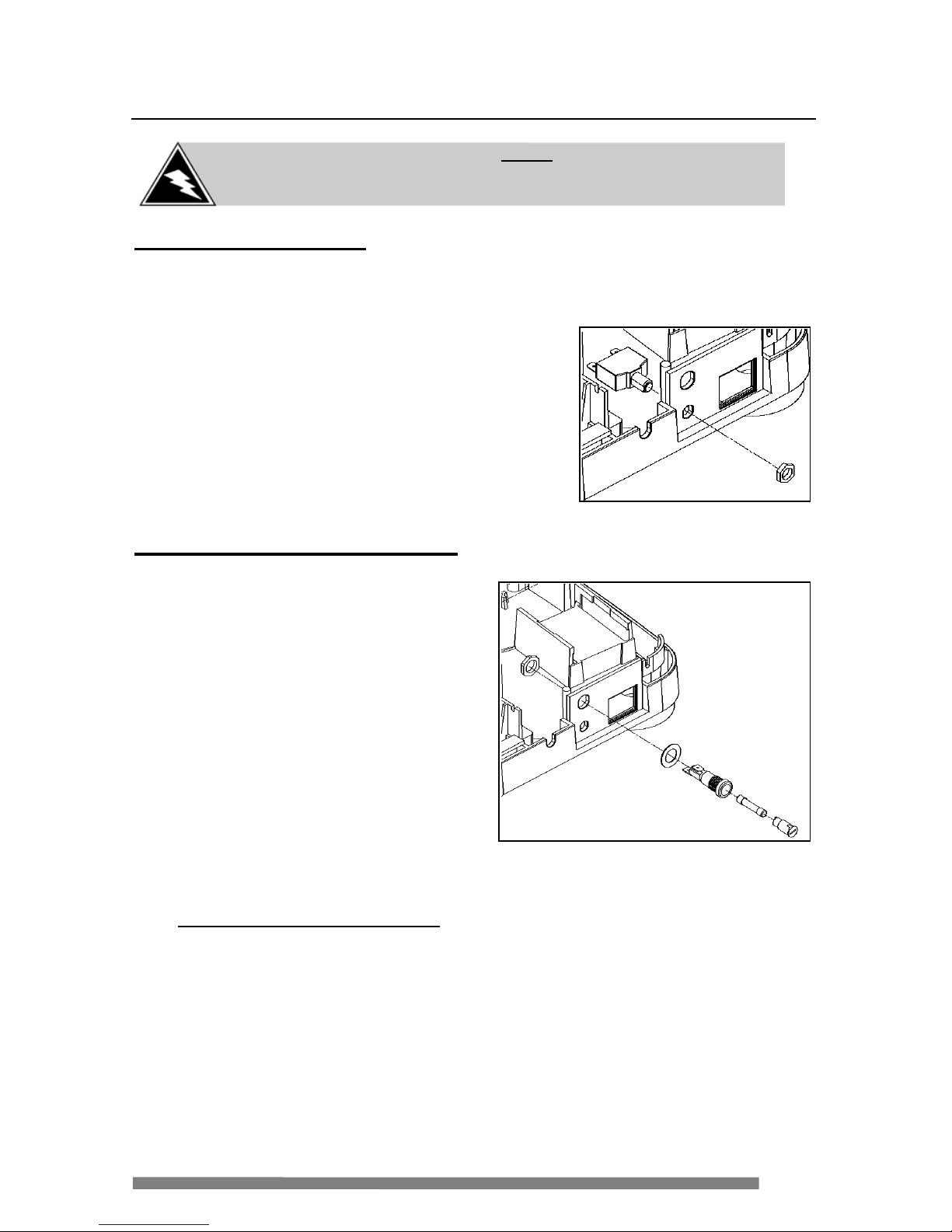
61
Replacing Major Components
5 Amp Circuit Breaker
1. Remove the hex nut secur ing the circ uit bre ak e r to the base.
2. Pull the circuit breaker through the insi de of the base until it is free.
3. Disconnect the two wires from the circuit
breaker.
4. Insert the new circuit breaker into the base
(from the inside towards the outside) and
secure it i n pl ace wi th the hex nut.
5. Reconnect the two wires to the rear of the
ci rcuit breaker.
15 Amp Fuse Holder Assembly
1. Remove the hex nut securing the
f use holder to the base.
2. Pull the fuse holder through the
outsid e of the base until it is free.
3. Disconnect the two wires from
the fuse holder.
4. Insert the new fuse holder into
the base (from the outside
towards the inside) and secure it
in place with the he x nut.
5. Reconnect the two wires to the
r e a r of the fuse holder .
Replacing the 15 Amp Fuse
1. I nsert the e n d of a blade scr e wdriver i nto t he fuse holder cap.
2. Turn the fuse holder cap unt il it pops loose and remove it.
3. Remove the blown fuse fr om the fuse holder cap a nd install a new one.
4. R e place the fuse holder cap and turn it with a blade screw dr iver to
lo c k it in p lace .
WARNING: The service cord MUST be disconnected from
the wall outlet prior to servicing. Failure to do so can result in
elect rical shock!
Page 62

62
Replacing Major Components
Power Supply
1. Remove the inle t val ve (page 50).
2. Remove the exhaust fa n (page 59).
3. Loosen the two screws on the side of the power supply that secure i t to the
base.
4. Lift a nd pul l the pow er supply out of the coffee maker (towards the rear).
5. D isconnect the ground wir e o n the side of the power supply.
6. D isconnect the upper c on nector (out put) from the other si de of the pow e r
supply.
7. D isconnect the lowe r connector ( input) from the othe r si de of the pow e r
supply.
8. I nsert the t wo mounting scr e ws about halfway into the side of the new
pow er supply.
9. Connect the u pper a nd lower c onn e c tors, a s well as the ground wire.
10. Slide the power supply ont o the base, a ll owing the two scr e ws to dr op into
the two sup ports on the base.
11. Tighten the two screws to secure the power supply on pl a c e .
12. Re-install the exhaust f a n.
13. Re-install the inlet valve.
WARNING: The service cord MUST be disconnected from
the wall outlet prior to servicing. Failure to do so can result in
elect rical shock!
Page 63

63
Replacing Major Components
Sensor Boards
1. D isconnect the wiring harness from the sensor boa rd.
2. Remove the fasteners sec uring the boa rd. Some boards are si mply clipped
in place and do not hav e faste ne rs.
3. Remove the sensor boa rd and re place it wi th a new one.
4. Secur e the r eplacement board i n pl ace (the milk conveyor sensor bo a rds
come with new r atchet fasteners – disca rd the old fasten ers and use the
new one s pr o vided). Som e boards are s i mply clipped in place and do not
have fasteners.
5. Connect the wiring har ne ss t o t he sensor board.
Cup Wa rmer (Professional Mod el)
I nstructions are provided wi th the repl acement cup warmer. Please follow these
instructions carefully.
The cup warmers can only be used on the Espresso Café
Pr ofe ss iona l m ode l. They c a nnot be ins t a lle d on a r e gula r m ode l
as th ey are no t compat ib le.
Once the cup warmers are installed, they require a 72 hour cure
ti me at ambien t temperature for the adhesive to set. DO NO T u s e
them for 72 hours or they will not adhere properly.
Page 64

64
Troubleshooting
Error Messages
If an error message is present on the coffee maker, you c a n u se the table below as a
reference to i solate and correct the problem.
ERRO R MESSAGE
ACTIONS REQUIRED T O RECTI FY ERROR
bre wer h ome
error 01
► Swit c h the cof fee maker power OF F for 10 sec onds ,
and swit c h it ON again. T he brewer w ill cy c le to
reset. If the err or per s is ts, c heck the brewer
assembly (including motor and s ensor board), wiring
and cont ro l boar d.
sta rt b utt on
ja mme d 02
► The gr een S TART butt on is s tuck in the pres s ed
posit ion. Release the butt on if it is jammed. If the
error persists, chec k
the S TART button cir c uit boar d.
wate r re se rv oir
i s e mpt y 03
► The r es er v oir is not f illing - check the ma in water
supply, inlet v alv e, water tubing and cont r ol board.
milk canister
i s e mpt y 04
► The em pty mi lk canist er must be replace d with a
new one. If the error per s is ts, check the lower
sensor boar ds on t he c onveyor.
► Milk canist er may not be ins talled properly.
mil k convey or
i s e mpt y 05
► This error is caused by eit her a faulty upper sensor
or a f aulty dis penser motor . Replace t he fault y
component.
mil k door
i s ope n 06
► Close t he milk door. If the error persists, check the
door sensor cir c uit boar d.
overflow
07
► Water ov er flow ins ide the cof fee maker (base).
Re move t he waste bin and clean the over flow using
a sponge or absorbent tow el.
po d se n so r
08
► The pod sensor on the brew er has detecte d
something. A pod m ay be jamme d or the brewer
sensor bo ard is faulty and must be re placed.
NOTE: The Es presso Caf é handheld programmer must be c onnec ted to
the coffee maker to view erro r messages.
Page 65

65
Troubleshooting
ERRO R MESSAGE
ACTIONS REQUIRED T O RECTIFY ERROR
he ate r sy stem
error 09
► A comp onent in t he heater s y s te m is not
func tioning. Check t he t hermal cutof f and heater
unit.
w ate r syste m
error 10
► A comp onent of the water s y s tem is not
func tioning. Check t he water pump, f low meter and
valves.
check j10
ha rne ss 11
► The har nes s is not connec ted t o the cont r ol boar d.
Reconnect the har ness.
check j23
ha rne ss 12
► The har nes s is not connec ted t o the cont r ol boar d.
Reconnect the har ness.
check
te mp h arnes s 13
► The temper ature harnes s is not connected t o the
cont r ol boar d. Rec onnect the harness or c heck the
temp er ature pro be.
Milk overflow
14
► The whipper bowl has overf lowed. O pen the top
cover and c lean the milk overf low by pouri ng water
directly onto the deflector underne ath the whipper
bow l. If nec es s ar y , use a small brush (and wat er )
to c lean the milk overflow.
Check whipper
Motor 16
► The whipper motor is not working. Check the motor
or wiring.
Handle position
Error
17
► The c off ee ma k er is detect ing two (or more)
select ions at onc e. Clea n s ens or s on s election
board or r eplac e s elec tion boar d.
Chec k waste bi n
Error
18
► Was te bi n m ay be f ull.
► Pod may be stuck on shelf below the brewer
(inside the mac hine). V er ify and clear pod.
Memory error
Option board 19
► The option c ir cuit board must be re placed.
►
In so me cases, a s oft ware upgrade may cor r ec t t he
problem.
NOTE: Sw itch OFF pow er to the coff ee maker bef ore disconnecting the
programmer.
Page 66

66
Troubleshooting
If the co ffee maker is not wor king properly, you c a n use the t a ble below as a
reference to i solate and correct t he problem.
SYMPTOM
W HAT TO DO
“Cal l fo r S ervice”
LED is lit (solid)
► Switch off the power to the coffee maker for ten seconds,
and switch the power back on. In some cases (pod jam),
this will clear the error.
► Connect the programmer to the coffee maker to check
the status. See the table above for the action required.
“Cal l fo r S ervice”
LED is flashing
► An interruption in the brew cycle occurred (power outage,
error, etc.). A quick-rinse cyc le must be performed to
clear this error.
“Emp ty Waste Bin”
LED is lit, but the
wa ste bin is e mpty
► A stray pod may have fallen on the internal shelf below
the brewer
►
Check the sensor boa rd
“Call for S ervic e”
LED is lit only w hen
selecting Café Latte or
Cappuccino
► The whipper bowl has overflowed. Clean the m ilk
overflow by pouring water directly onto the deflector
underneath the whipper bowl. If necessary, use a small
brush (and water) to clean the milk overflow.
15 Amp fuse k eeps
blowing
► Check the w ater heater.
► Check the thermal cut-off switch
►
Check wiring to heater assembly
5 Amp circuit
breaker k eeps
tripping
► Inspect sy stem for water leaks, especially on electrical
components
► Check all low power components
► Check electronic board s
►
Check wiring
Cup level t oo low
► Check for lea ks/pre ssure loss in the water system
► Check the flow meter
►
Check the water pump
Inc onsi stent water
level
► Check the routing of the tubing
► Check the flow meter
►
Check the water pump
Pressure release
keeps opening
during a brew c ycle
► Brew head may be clogged
► Tu bing in water system may be kinked or have an
obstruction
On initial power-up,
the machine doe s
not stop dispe nsing
water from the spout
► Check the w ater detection manifold. The detection
screws may need to be removed and clea ned.
► Check the w iring to the manifold and board
Water is be ing
dispensed o n and off
for short period s of
time (about every 10
seconds)
► Check the connections to the f low meter
► Open and clean the flow meter
► Replace the f low meter
Page 67

67
FAQ (Frequently Asked Questions)
Q Can the cof f ee maker be installed outdoors?
A No. This coffee maker is designed for indoor use only.
Q Can any type of dehydrated milk be used in the coff ee maker?
A No. Other dehydrated milk products should not be used because they may not work
properly. Extensive testing was done in this area by the equipment manufacturer
and the milk supplier to provide the best product possible for this type of
application.
Q Can flavored powder be used instead of dehydrated milk?
A No. This coffee maker was not designed to be used with products containing sugars
and may be severely damaged by these types of products.
Q Can whole coff ee beans be used i n th is co f fee maker?
A No. This coffee maker uses coffee pods specifically designed to be used with the
incorporated brewing system.
Q Can the cof f ee po ds b e re-used?
A No. Once the pod has been used, it cannot be re-used and must be discarded.
Q Should I empty the milk and water before removing or relocating the
cof f ee maker?
A Yes. Milk and water must be emptied prior to removing or relocating the coffee
maker. If they are not emptied, damage will result to internal components and the
electronics.
Page 68

68
Page 69
VKI Publication # 100218-001 February 2012
Manuel d’opér ati on & servi ce
28 juillet, 2005
Page 70

2
Page 71

3
Table des matières
Informa tion sur la sécurité ............................................................ 5
Spécifications de la cafetière ........................................................ 7
Survol de la cafetière..................................................................... 8
Identificat ion des pi èc es ......................................................................................8
Panneau indicat eur de statut du système ........................................................9
Poignée de sélection de produit .........................................................................9
Couverc le du r éceptac le (M odèle P r ofessional se ulement) ........................10
Chauffe-t asse s (Modèle P r ofe s sion al seuleme nt) ........................................10
Branchem ent sur une conduite d’ eau ......................................... 11
Install ation du kit de dra i nage ..................................................... 13
Install er le contenant de lait ........................................................ 15
Utilisation de la cafetière ............................................................. 16
Do se de caf é .......................................................................................................16
Infuser u n br euvage ...........................................................................................16
Types de Breuva ges Disponi bles ................................................ 17
Brancher le Programmateur ........................................................ 18
Progra m me d e diagnostic au démarrage .......................................................19
Ca ractéristiques logicielles ......................................................... 20
Navigat ion dans le me nu du logiciel ................................................................20
Télécharger le logiciel ................................................................. 23
Entretien...................................................................................... 24
Vider le bac à déc hets .......................................................................................24
Nettoyage d’un déborde ment de lait ................................................................24
Vider le platea u d’égoutt ement.........................................................................25
Cycle de r inçage .................................................................................................26
Cycle de r inç age forc é .......................................................................................26
Amorçage du système d’eau (à la mise e n m ar c he) ....................................27
Emplac ement des tuyaux dans le bec de dist r ibution ..................................27
Utilisation de l a lang uet te de net toyage .......................................... 28
Vider le lait et l’eau à l’aide de la lan guett e de nett oyage............................31
Nettoya ge du convoyeur de l ait................................................... 32
Ouv rir le couv ercle..............................................................................................32
Nettoyer le convoy eur de lait à l’aide d’un as pir ateur ...................................33
Nettoyage manuel du convoyeur de lait..........................................................34
Page 72

4
Table des matières
Retirer la cafetière ....................................................................... 37
Vider le c onvoy eur à lait ....................................................................................37
Drainer l’e au ........................................................................................................38
Ent r eposa ge de la cafet ièr e ..............................................................................39
Information s Générales ............................................................... 40
Rempl ace ment de s composantes ............................................... 41
Ouv rir le couv ercle..............................................................................................41
Enlever le couvercle et le panneau de c onto ur..............................................42
Enlever le couvercle ....................................................................................... 42
Enlever le panneau de contou r....................................................................... 43
Infuseur.................................................................................................................44
Têtes de l’infuseur .......................................................................................... 44
Mot eur de l’infu se ur ............................................................................................45
Anneau de sélec tion & P laquett e .....................................................................45
Chauffe-eau .........................................................................................................46
Sonde de t em pér ature .......................................................................................47
Rupteur thermique ..............................................................................................47
Ré servoir d’e au ...................................................................................................48
Interr upteur de niveau d’eau à flotte................................................................49
Valve d’entrée .....................................................................................................50
Valves de sortie...................................................................................................51
Reconstruire un e valve de sort ie......................................................................52
Plaquet te de cont r ôle & Plaquet te d’options ..................................................53
Pompe à eau .......................................................................................................54
Harnais/ P ont de di odes de la pomp e à eau ...................................................55
Convoyeur de lait et moteur du di str ibuteur ...................................................56
Mot eur du fouetteur ............................................................................................57
Débitmètre ...........................................................................................................58
Ventilateur d’évacuat ion ....................................................................................59
Interr upteur princip al ..........................................................................................60
Coupe-circuit de 5 Ampères .............................................................................61
Support de f usible de 15 Ampères ..................................................................61
Remplacer le fusible de 15 Ampères.............................................................. 61
Bloc d’alime ntat ion .............................................................................................62
Plaquet tes de détec teurs...................................................................................63
Dépannage .................................................................................. 64
Message s d ’er r eur ..............................................................................................64
FAQ (Foire Aux Questions) ......................................................... 67
Page 73

5
Information sur la sécurité
Votre sécurité est très importante pour nous. Il est impératif que
v ous lis iez et c om preniez c ette inf orm ation s ur la s éc urit é avant
de
débuter l’installation et l’exploitation de cet équipement.
Cette cafetière est conçue pour usage intérieur SEULEMENT et ne doit
jamais être installée à l ’extérieur
.
Cet appareil doit être positionné de façon à ce que la prise murale et
l’i nt e rrupteur principa l soient facilement accessi bles.
Ne pas brancher la cafetière dans une prise ayant un voltage différent de
celui ind iqué sur le décalque du numéro de série.
Ne jam ais immerger la caf etière ou toute partie de cette cafetière.
Pour éviter tout danger, la cafetière doit être installée sur une surface à
niveau. Si la cafetière ne semble pas stable, choisissez un autre
emplacement pour l’installation
.
Lorsque la cafetière est mise sous tension, une petite quantité d’eau peut
être distribuée alors que le système est purgé. Cette eau peut être chaude
alors tenez vous loin de l’air e d e distr ibution
.
Pour prévenir de sérieuses blessures ou brûlures, ne pas mettre les doigts
directement dans l’ouvertur e pour la dose de café et ne pl acer aucune partie
du corps a u de ssus de l’ouve rture pour la dose de c a fé
.
Garde z vos mains loin d e l’espace d e distribu tion à l’avant de la cafetière.
Les liquides distribués sont extrêmement chauds et peuvent causer des
br ûlure s sévères
.
Ne jama is insérer vos d oigts dans le réceptacle de la do s e de café lorsq ue
l ’appareil est allumé.
Ne ja ma is débrancher la cafetière en tirant s ur le fil é lectrique et ne jamais
utiliser la cafetière si le fil électrique est endom magé.
Ne ja ma is tenter de désactiver les caractéristiques de sécurité incorporées
dans la cafetière. Elles sont là pour votre protection et ne doivent être
désactivées sous a ucunes circonstances
.
Cette machine doit être utilisée spécifiqu ement pour l’usage p ou r laquelle
elle a été conçue. Le manufacturier n’est pas responsable pour tout
dommage ou blessure résulta nt d’une ma uvaise utilisation de la machine.
Page 74

6
Information sur la sécurité
I l faut toujo urs éteindre et débrancher le cordon électrique lors du nettoyage de
l’intérieur de la cafetière. Les composantes à l’intérieur de la cafetière peuvent
causer des chocs électri ques qui peuvent pr ovoquer des blessures
.
Si la cafetière ne fonctionne pas convenablement ou semble avoir un
problème , éteind re la cafetière, débranchez le cordo n électriq ue et app elez
un technicien autorisé immédiatement. Seulement le personnel qualifié
devrait effectuer le service sur cette cafetière
.
La majo rité des compos antes électrique de l’Es pres so Café fonctionnent à
bas voltage (et non 120 volts AC). Ne jamais brancher ces composantes
sur le 120 volts AC.
Le sy s tème pou r l’eau d ans cette cafetière est pressuris é. La p ress ion doit
être rel âchée avant d’effectuer l e service sur le syst ème
.
Faire preuve d e prudence lorsque v ous faites le service s ur le chauf fe-eau
ou les valves de sortie, car ils peuvent être extrême ment chauds et causer
de sévères brûlure s
.
Faire preuve de prudence lorsque vous travaillez à l’intérieur de la
cafetière, car il peut y avoir des composantes aux bordures acérées qui
peuven t causer des coupures
.
Pour prévenir les chocs électriques, enlevez tous bijou x (bagues, montres,
etc.) lorsque vous faites le service sur la cafetière
.
Utilisez seulement des pièces de rempla cement originales. D es pièces de
remplacement non approuvées peuvent causer des blessures, feux et/ou
autres dommages à l a cafeti ère
.
Ne pas soulever la cafetière par le plateau d’égouttement. Soulever la
cafetière uniquement par les côtés.
Ne pas permettre l’accès à cette cafetière aux enfants. Ils ne sont pas
conscients des danger s encourus
.
NOTE:
Lorsque l’appareil doit être éteint, attendez au moins
5 secondes avant de le rallumer.
Les m od if ica tio ns non autorisées faites sur cette cafetière peuvent
provoquer de sér ieuses blessures et /o u des dommages à l a cafetière,
et annulent toutes ga ranti es et certifications.
Page 75

7
Spécifications de la cafetière
Voltage
120 volts AC
Pui ss anc e du c hau ff e-eau 1000 watts
Poids 17 kg (38 lbs)
Formats de tasse
– Espresso 45 ml (1.5 oz liq.)
– Cappuccino
210 ml (7.0 oz liq.)
– Caffè Latte
210 ml (7.0 oz liq.)
– Ameri cano
175 ml (6.0 oz liq.)
Contenance du chauffe-eau 420 ml (14 oz liq.)
Con t ena nc e du r és ervoi r d’ eau 1 litre (34 oz liq.)
Contrôle de température Sonde de température électronique
Temps de chauffage
2 minutes après la mise en marche initiale
Température d’infusion*
96°C (194°F)
Temps d’infusion
– Espresso
30 secondes
– Cappuccino 50 secondes
– C a ffè L at te 45 secondes
– Ameri cano
50 secondes
Pro t ecti on du c hau ffe-eau
Oui
Protection de débordement
Oui
Prote ction de circuit • Coupe-circuit de 5-amp pour l’électronique, les
valves et les moteurs
• Fusible de 15-amp pour le chauffe-eau
Certification • CSA, UL, NSF
*NOTE: Pour les ins t al la ti ons en ha ut e alt itude, v euillez con t a cte r vo tr e di s trib ut e ur ou le manu f a cturier pour
un logiciel s pé cial “
HAUTE ALTITUDE”.
Dim ensions de la cafetière
Hauteur:
42.5 centimètres (16 ¾ pouce s)
Largeur:
51 centimètres (20 ⅛ pouces)
Profondeur:
39 centimètres (15 ¼ pouces)
Exigences d’installation
Hauteur:
42.5 centimètres (16 ¾ pouce s)
Largeur:
51 centimètres (20 ⅛ pouces)
Profondeur:
45 centimètres (17 ¾ pou ce s)
Pour maintenir la certification NSF de cet appareil, vous devez utiliser seulement
les pièces originales du m anufactur ier. L’utilisation de pièce s pr ovenant d’une
source alternati ve annulera la certification NSF ainsi que la garantie de l’appareil.
Page 76

8
Survol de la cafetière
Identification des pièces
Réceptacle de la
dose de café
Panneau
indicateur du
statut du système
Plateau
d’égouttement
Bouton de
mise en
marche
Poignée de
sélection de
produit
Réceptacle
du contenant
de lait
Chauffe tasses
(Modèle Profes siona l
seulement)
Décalque de
numéro de série
Plateau d’égouttement
Bac à
déchets
Valve
d’entrée
Cordon
électrique
Interrupteur
Coupe-circuit
Vue arrière de la Machin e
Page 77
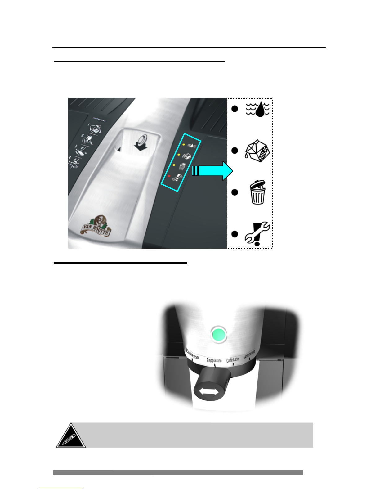
9
Survol de la cafetière
Panneau indicateur de statut du système
Le panneau indicateur de statut du système (situé à l a dr oite du réceptacle de la
dose de café) transmet de l’information au sujet de t out entr e t ien qui pour rai t
être requis.
Poignée de sélection d e produit
Pour sélectionner un produit, déplacer la poignée vers la gauche ou vers la
dr oite pour l’ aligner avec le produit dé siré. Appuyez ensuit e sur bou t on de mise
en mar c he pour débuter le cycle d’inf usion.
Manque d’eau
– vérifiez
l’alimentation
d’eau.
Remplacez le
contenant de
lait
Videz le bac à
déchets
Appelez pour
le service
Voir page 17 pour
une description des
produits disponibles
NOTE: La poignée est conçue pour descendre et se détacher si elle est
soumis e à tr op de press ion. Si c ela s e pr oduit, simplement la réinstaller en
lui donnant un angle.
Page 78

10
Survol de la cafetière
Couvercle du réceptacle (Modèl e Professional seulement)
Le modèle Espress o Café Professional
es t expédié avec un couvercle pour le
réceptacle de la dose de café. Le
couvercle devrait resté installé sur
l’appareil lorsqu’il n’est pas en
fonction et devrait être enlevé lors de
la préparation d’un breuvage. Après la
préparation du breuvage, replacez le
couvercle sur le réceptacle pour
empêcher la chute de corps étrangers
dans l ’infuseur.
Chauffe-tass es ( Modèle Professional seul ement)
L’Espresso Café modèle Professional est muni de chauffe-tasses. Placez les
tasses de verre ou de céramique à l’envers s ur les chauffe -tas ses et laiss ez-les
en place jusqu’à ce qu’elles soient requises (à ce moment, elles s eront tièdes au
toucher).
Chauffe-tasses
Page 79

11
Branchement sur une conduite d’eau
Toutes les machines Espresso Café doivent être installées avec un système de
filtration d’eau Everpure. Ce système est composé d’une tête de filtre QL3
(équipée d’une valve) et d’une cartouche de filtration 4H. Ce système est
compatible avec la cartouche d’assainissement Everpure modèle JT, qui est
requise pour effectuer le cycle de nettoyage conformément avec les standards
NSF.
NOTE: Le filtre à eau doit ê t re in stal l é ent re l a sou rce d’ eau et l a c afet iè re (à un
maximum de 3 pi eds de la cafetière
). Veuillez noter aussi que la valve d’admission
es t é qu i pé e d’ u n ré gulat eur de dé bit ai nsi que d’ u n disposit if a nt i-refoulement.
DÉBIT D’EAU
TÊ TE DU F IL TR E
EVERPURE QL3
CARTOUCHE FILTRANTE
EVERPURE 4H
NOTE : La cartouche filtrante est enlevée e
remplacée avec la cartouche d’assainissemen
Everpure JT lorsque le cycle de nettoyage
(as sai nisse ment) es t effect ué.
Page 80

12
Branchement sur une conduite d’eau
1. Brancher un raccord d’entrée de ¾ de pouce sur la valve d’entrée située à l’arrière
de la cafetière. S’assurer que la « rondelle » de caoutchouc est insérée entre le
raccord et la valve d’entrée.
2. Serrer le raccord sur la valve d’entrée – Serrer à la main seulement. Brancher le
tuyau d’eau au raccord et installer le clip de verrouillage pour le verrouiller en
place
.
3.
Ouvrir la valve d’eau à la source, vérifier qu’il n’y a pas de fuites, les réparer si
nécessaire.
4.
Brancher le cordon de service dans une prise murale et mettre l’interrupteur de la
cafetière à «ON »
.
5. Vérifier encore une fois s’il y a des fuites et les réparer si nécessaire.
AVERTISSEMENT: Placez une tasse sur le plateau d’égouttement lorsque
la cafetière est remplie d’eau pour la première fois. Il y a env iron 50 ml
d’eau qui sera distribué par le bec à cause de la purge du système d’eau.
NOT E: Cet équipement doit être installé en conformité avec les
codes de plomberie fédéraux, provinciaux et locaux.
* L'illustration est pour la
référence seulement.
Ne pas t rop serrer le racco rd
d’ad mission car cela peut
empêcher l ’eau de ci rculer.
Page 81

13
Installation du kit de drainage
Pour ins taller un kit de drainage sur une Es pres so Café, le p lateau d’égouttement
doit être modifié dans le but d’enlever le support de la flotte et créer un trou de
drainage.
1. Enleve z la gril le du platea u d’égouttement.
2. Enleve z le clip qui r e ti e nt la flotte à son support.
3. Enlevez la flotte.
4. Tournez l e platea u d’égouttement à l’e nve rs.
5. À l’ ai de d’une mèche de ¼”, pe rcez un tr ou de guidage à l’empl acem ent
indiqué.
6. À l’ ai de d’une mèche de 3/8 ” agrandissez le tr ou de guidage.
7. C eci enlèvera l e support de la fl otte et créera un conduit pour le système de
drainage.
Page 82

14
Installation du kit de drainage
8. B ranchez le tuyau de drainage au raccor d de drainage sous l’ avant de la
machine. L e tuyau doi t êtr e dirigé vers le bas – ne pas passer le tuya u sous
la machine.
9. Fixez le tuyau de drainage au raccor d à l’ aide de la bride de plastique.
10. Branchez l ’autre bout du tuy au au système de drai na ge qu i sera utilisé sur
place.
11. Branchez l e programmateur et allum ez la cafeti ère.
12. Défil ez jusqu’a u menu “
DRAIN INSTALLED?” et appuye z sur le bouton
<
MISE EN MARCHE> d e la machine.
13. Appuye z sur le bouton “a ugmenter” du progra mmateur – la deuxième ligne
de l’affi cheur devrait afficher “
YES ”.
Ceci lai sse savoir à l a machi ne qu’un drain es t installé réduis ant le
nom bre d’interventions que l’ut ilisate ur doit effe c t ue r pendant un “
CYCLE
DE NETTOYAGE
/ASSAINISSEMENT” s i jamais c e lui-c i devait s’avérer
nécessaire.
14. Appuye z sur le bouton “
DÉFILEZ V ERS LE HAUT” pour sau v e ga rder vos
réglages.
Bride
Tuyau
Raccord
Page 83

15
Installer le contenant de lait
1. Ouvrez le couvercle du lait sur le côté supérieur gauche de la cafetière.
2. Enlevez le contenant de lait vide (si vous le remplacez).
3. Enlevez le couvercle du contenant vide.
4. Enlevez le sceau de fraîcheur du nouveau contenant.
5. Installez le couvercle sur le nouveau contenant.
6. Installez le nouveau contenant dans la machine en le poussant vers le bas dans le
réceptacle.
7. Fermez le couvercle du lait de la machine.
NOTE: Lorsque le contenant de lait est initialement ins tallé, ou lorsque remplacé,
le moteur du distributeur de lait peut se mettre en marche automatiquement pour
amorcer le système du lait. Lorsque le système est amorcé, le m oteur s’arrête.
NOTE: Ne pas enlever et ins érer le contenant de lait à répétition c ar cela peut
e
ntasser le lait au bas du convoyeur et peut causer un blocage. Une fois installé,
laissez le en place jusqu’à ce qu’il soit nécessaire de l’enlever.
NOTE: Lorsque le contenant de lait est vide, toutes les sélections requérant
du lait sont désactivée s et le bouton de mise en marche est éteint.
Page 84

16
Utilisation de la cafetière
Dose d e café
Infuser un breuvage
NOT E: Ne ja mais insér er une dos e de caf é dans le r éc eptac le pendant que la
cafetière est en train de préparer un breuvage. Ne pas insérer de doses de café
déformées dans le réceptacle car elles peuvent rester bloquées dans l’infuseur.
Emballage de la dos e Dose de ca fé
Ouvrez l’emballage et
retirez la dose.
Insére z la dose dans la fente
sur l e de ssu s d e l a caf etière.
Choisissez le produit désiré en
dépl açant l a poi gné e de séle ction
vers la gauch e ou vers la droite.
Appuyez sur le bouton vert de
mise en ma r ch e s it ué au d es s us
de l a poi g n é e de séle ct i on.
Page 85

17
Types de Breuvages Disponibles
Espresso – L'or iginal au goût franc,
plei n de r ondeur, r ec ouv er t d'une
mousse dorée ap pelée crema
Cappuccino – Espresso simple
garni de lait c haud et de mou s se d e
lait
Caffè Latte – Espresso simple
mélangé avec une gé nér euse
port ion de lait chaud légèr ement
mousseux
Americano* (Modèle standard seu lem ent) –
Un Espr esso allo ngé avec de l’eau
chaude
*Cette option s’applique au modèle standa rd seulement. Le breuv age “Amer icano”
est remplacé par l’ “EA U CHAUDE” sur le modèle Profe ssiona l.
NOTE: Les illustrations ci-dessus sont destinées à être utilisées comme
description de produit seulement. Le produit final peut ne pas ressembler à ces
illustrations.
Lait et
Mousse
Lait et
Mousse
Eau
chaude
Page 86

18
Brancher le programmateur
Le programmateur por tatif (ve ndu sépa rément) agi t en interface avec l a cafetière,
vous permettant de vo ir les messages d'er reur e t vous donnant ac c ès aux fonctions
du logiciel incorpor ées à la machine.
Programmateur Espresso Café
NOTE: Le tableau de statut de l’appareil fourni des messages concernant des
actions mineures à effe ctuer sur la ca fetière. Cependant, si la lumière rouge est
allumée, le programmateur doit être branché pour voir l’erreu r présente.
Page 87

19
Brancher le Programmateur
Pour br ancher le programmateur portati f à l a cafetière,
1.
Mettre l’interrupteur de courant de la cafetière à la position fermée (0).
2. Retirer le bac à déchets.
3. Localiser le port d’interface du programmateur sur la surface arrière de l’espace
réservé au bac à déchets.
4. Brancher le câble de style téléphonique du programmateur au port d’interface.
5. Mettre l’interrupteur de courant de la cafetière à la position ouverte (I).
Programme de diagnostic au démarrage
Lorsque le programmateur est branché et que la cafetière est mise en marche, la version
du logi ciel est affichée et un p rogramme de dia gnost ic est mis en marche pour chercher
toute erreur de fonctionnement de la machine. Si un problème est détecté, le
programmateur peut être utilisé pour identifier le problème.
De l’information plus d étaillée au s ujet des mess ag es d’erreur et de la manière
de les régler se trouve dans la section “Dépannage” de ce manuel (page 64).
Page 88

20
Caractéristiques logicielles
Étein dre la cafetière et brancher le programmateur portatif à la cafetière et utiliser
les boutons <
DÉFILER VERS LE HAUT> et <D ÉFILER V ERS LE BAS > pour na viguer
dans le log iciel.
Navigation dans le menu du logiciel
MENU PR INCIPA L
S OUS MENU
Procédure
Empt y cycle
Pre ss st art
Appuyer sur le bouton de mise en
marche pour entrer dans le menu.
Empty milk
Press start
Retirer le co ntenant de lait et
appuyer sur le bouton de mise en
marche pour vider le convoyeur à
lait.
Close milk
Door
La porte de lait doit être fermée
pour con tinuer le cycle.
Emptying
Please wait
Attendre que le cy cle so it complété.
rem ove
mil k caniste r
* Si le contenant de lait n’a pas été
enlevé, ce rappel apparaîtra à
l’écran.
Emp ty water
Press start
Débranc hez l’arrivée d’e au de la
cafetière. Lorsque le cycle « Vider
le lait » est complété, ce message
apparaît à l’écran. À ce moment,
placer le bac à déchets sou s le bec
de distribution.
Emptying
Please wait
De l’eau s’écoulera du bec de
distribution dans le bac à déchets.
Attendre que le cy cle so it complété.
Instal l drain
insert - star t
In sta ller l’ in sert ion de d ra inage dan s le
raccord de drainage situé sous la
cafetière. Appuyez sur le b outon de
mise en marche pour v ider l’eau
rest ant e dan s le cha uffe -eau.
Emptying-power
Off when done
Attend re que le cycle so it comp lété,
éteindr e l’inter rupteur de cou rant et
débrancher le cordon électrique de la
prise de couran t.
NOTE: Les réglag
es de quantité de lait et d’eau sont faits lorsque la cafetière est
produite en usine. Ces réglages ne peuvent pas être modifiés (sauf pour ajuster l e
format à 6 ou 7 oz) puisque aucun ajustement n’est requis sur ce t équipement.
Page 89

21
Caractéristiques logicielles
Navigation dans le menu du logiciel (suite)
MENU PR INCIPA L
S OUS MENU Procédures
Handle position
xxxxxxxxxxx
Une fois ce menu affiché,
déplacer la po ignée de sélect ion
d’un produit à l’autre pour tester.
Handle position
Cappuccino
Ce message est affiché lorsque la
poignée de sélection est placée à
la position Cappuccino.
Handle position
Espresso
Ce message est affiché lorsque
la poignée de sélection est
placée à la position Espresso.
Handle position
Americano
(hot Wa ter –
modèle Pr of essional )
Ce message est affiché lorsque
la poignée de sélection est
placée à la position Americano
(“Eau chaude” sur le modèle
Professional).
Handle position
Caff e latte
Ce message est affiché lorsque
la poignée de sélection est
placée à la position Caffè Latte.
Handle position
Error
Une erreur a été dét ectée avec
le posit ionnement de la poignée
de sélection.
Se ri al nu mbe r
Pre ss st art
App uye r su r le bo ut on de m ise en
marche pour entrer dans le menu.
Pnb control
xxxx- xxxx- xx x
Le numéro de série du panneau
de contrôle est affiché.
Options type 1
xxxx- xxxx- xx x
Le numéro de série de la
plaquette d’options est affiché.
Se t cu p size
Pre ss st art
Appuye r sur le bou ton de m ise en
marc he pou r entre r dans le menu .
Set cup size
7 oz
Appuyez sur le bouton
“Augmenter +” ou “Dimi nuer -”
du programmateur pour choisir
le format 6-oz ou 7-oz.
NOTE: Appuy ez su r le bou ton
“
DÉFILER VERS LE HAUT” ou
“
DÉFILER VERS LE BAS” pour
sauvegarde r les changement s.
Page 90

22
Caractéristiques logicielles
Navigation dans le menu du logiciel (suite)
Sele ct reg/pro
Pre ss st art
Appuyer sur le bouton de mi se en
marche pour entrer dans le menu.
Sel ect reg/pro
reg
Appuyez sur le bouton “Augmenter +”
ou “Diminuer -” du programm ateur pour
choisir REG (m odèle r égulier) ou PRO
(modèle Professional).
Se t hot wate r
Pre ss st ar t
NOTE : C e menu apparaît seulement
si la machine est réglée sur PRO
(modèle Professional).
Appuyer sur le bouton de mi se en
marche pour entrer dans le menu.
SeT hot w a ter
press-hold
Appuyez sur le bouton “Augment er +”
ou “Diminuer -” du programmateur pour
ajus ter la quantité d’eau à être distribuée.
La mac hi n e pe ut être réglé e à “PRESS
& HOLD” (l ’eau est distri buée aussi
longtemps que le bouton vert <MISE
EN MARCHE> es t app uyé) o u à la
tasse mesurée e n onces
( com mença nt à 1-oz et augmentant
de 0.5-
oz jusqu’ à un maximum de 10
-
oz).
Drain installed?
Pre ss st art
Appuyer sur le bouton de mi se en
marche pour entrer dans le menu.
Drain
installed? no
Appuyez sur le bouton “Augmenter
+” ou “Diminuer -” du
programmateur pour choisi r “YES” ou
“NO” (oui ou non) .
Pour over mode
Pre ss st art
Appuyer sur le bouton de mi se en
marche pour entrer dans le menu.
Pour Over
Mode off
Appuyez sur le bouton “Augmenter
+” ou “Diminuer -” du
programmateur pour choisi r “OFF” ou
“ON” (dés activé ou activé) .
Check for errors
Press start
Appuyer sur le bouton de mi se en
marche pour entrer dans le menu.
Lorsque cette fonction est activée, la cafetière effectue un
diagnostic rapide. Si une erreur est détectée, elle sera
aff ic h ée dans ce m enu.
NOTE: Éteindre le courant de la cafetière avant de débrancher le
programmateur.
Page 91

23
Télécharger le logiciel
Si une mise à jour est requise pour l’Espress o Café, la mise à jour sera expédiée
s ous forme d ’ EPROM. À l’exception du téléchargeur Espresso Café, aucun outil
spécial ou changement de pi èce n’ est requis pour télécharger le log iciel.
Pour mettre à jour le logiciel dans l’E spresso Caf é:
1. Installez l’EPRO M conte nant l a mise à j our logi cielle dans le tél échar geur
Espresso Café.
a) Enle v e z les vis e n haut e t e n bas du boîtier (figur e 1), ensuite
soulevez et enlevez le couvercle.
b) À l’aide d’un tournevis plat, soulevez le haut et le bas de l’
EPROM
existant (si installé ) et enlevez le l ors qu’il se libère.
c) L’ encoche de l’
EPROM poin tant ver s le haut, alignez l e s deux
rangées de pattes avec les deux rangées s ur le support et insér ez
doucement l’
EPROM (figure 2). Assurez-vous de ne pas plier aucune
patte entre l’
EPROM et le supp ort.
d) I nspect e z les pat te s une fois de plus pour v ous assure r qu’ e l le s sont
bien insér é e s dans le support .
e) Réi nstallez le couv e rcle sur l e programmateur.
2. Éteignez l a ca fetièr e et enlevez le bac à déchets.
3. B ranchez le programmateur.
4. Appuyez et maintenez le bouton <DÉFIL ER VERS LE B AS > (bouton le pl u s
bas) sur le programmateur et allum ez l’Espresso Café. Lor sque le
tél échar gement commence (les DELs commencent à clignoter), relâche z le
bouton.
5. Lorsque l e téléchargement est com plété, éteig nez l’Espresso Café,
débranchez le programmateur et r eplacez le bac à déchets.
Enlev ez
les vi s
EPRO M
Encoche
sur l’
EPRO M
Figure 1
Figure 2
Page 92

24
Entretien
V ider le bac à déchets
Le bac à déchet situé à l ’i ntérie ur de l a cafetière conti ent environ 30 doses de
café usagées. Le système est muni d’ un dé te cteur optique qui reconna ît que le
bac est rempli et vous averti par une l umière jaune «Vider le bac à déchets »
si tuée sur le panneau de sta tut de l’a ppa rei l.
Pour vider le bac à déchets:
1. Saisir la poignée à l’avant du bac à déchets.
2. Tirez le bac à déchets vers vous.
3. Videz le contenu.
4. À l’aide d’une éponge ou d’un chiffon absorbant, nettoyer tout liquide se
trouvant dans l’espace réservé au bac à déchets (la base).
5. Remettre le bac à déchets en position.
Nettoyage d’un débordement de lait
Cet appareil est équipé d’un s ys tème de détection de débordement de lait. S’il y
avait un débordement de la chambre du fouetteur, le lait, s’écoulera sur deux
contacts de débordement et une erreur de « Débordement de lait » s’affichera
sur le programmateur.
P our nettoyer le débordement de lai t:
1. Avec le couvercle de haut ouvert, nettoyez le lait de la cuvette du
f oue t te ur, la chambre du fouetteur et les tubes du sys t è me de lait.
2. Localisez les capteurs de
débo rdement de lait (sur le déflecteur
en dessous de la chambre du
fouetteur) et nettoyez le débordement
s ur le déflecteur et les capteu rs. Si le
lait durcie, utilisez une petite brosse
pour le libére r. Le la it et l’eau vont
s’écouler le long du déflecteur et
dans le bac à déchets.
3. U ne fois nettoyé, fermez le couvercl e
du haut.
NOT E: Si un débordem ent de lait est détecté, le voyant rouge « Appeler pour
service
» va s’allumer lorsqu’un Cappuccino ou un Café Latte sera
sélectionné.
Page 93

25
Entretien
V ider le plateau d’égouttement
Le p lat eau d ’égout t ement à l’ avant d e la
machine contient environ 500 ml de
liquide.
Lorsque trop de liquide s’est
accumulé dans le plateau, un flotteur
mont er a et s aillira de la gr ill e du p lat eau
d’égouttement. Lorsque cette situation
se présente, le plateau d’égouttement
doit être vidé.
Pour vider le plateau d’égouttement:
1. Saisir les extrémités du plateau d’égouttement.
2. Enlevez le plateau en le tirant vers vous.
3. Videz le contenu du plateau, et nettoyer celui-ci à l’ eau cou rant e.
4. Retirer le bac à déchets.
5. À l ’aide d’une éponge ou d’u n c hiffon absor ban t, nettoyer tout
l iquide se trouvant dans l’ espace réservé au bac à déc hets (l a base).
6.
Réinstallez le plateau d’égouttement en le glissant en position jusqu’à ce
qu’il se bloque.
NOTE: Lorsque le plateau d’égouttement est enlevé, le décalque du numéro de
série peut êtr e vu. Ce d éca lque mo ntr e aussi l es s pécific at i ons é l ectr iq u es de l a
machine, ainsi que les cer tifications de la machine (CSA, UL, etc.)
Page 94

26
Entretien
Cy cle de rinçage
Le cycle de rinçage doit être fait périodiquement pour nettoyer le système de distribution
du lait . Il est recommandé de f aire un cy cle de rinçage à chaqu e fois qu e le c lient est
visité pour un livraison ou par du personnel de service.
1. La cafetière étant allumée, mettre la poignée de sélection ENTRE deux
sélections.
2. Tirez le bac à déchets et placez-le sous le bec de distribution.
3. Appuyez sur le bouton vert de mise en marche pour activer le cycle de rinçage.
4. Répétez le cycle (si nécessaire) en appuyant de nouveau sur le bouton vert de
mise en marche.
Cy cle de rinçage forcé
Si un cycle de Cappuccino ou Café Latté est interrompu pour une raison ou une
autre (coupure de courant, erreur dét ectée, etc.) et ne peu t être comp lété, la DEL
de service rouge clignotera. Si cela se produit, un cycle de rinçage doit être
effectué pour effacer l’erreur et pour empêcher le lait de s’accumuler dans le
f oue t te ur et les tuyaux.
NOTE: Si le DEL ROUGE (clé) clignote, un cycle de rinçage doit être
effectué car c’est la seule façon d’effa cer cett e erreur.
NOTE: Le cycle de rin çage peut être annulé en tous temps en
appuyant sur le bouton de mise en marche.
NOTE: Ne pas éteindre la cafetière pour une période d’au moins 20 m inutes
après qu’un cycle de rinçage soit complété. L’humidité présente dans la
cafetière après un cycle de rinçage doit être évacuée par le ventilateur.
Page 95

27
Entretien
Am orça ge du système d’eau (à la mise en marche)
Lors de l’entretien du système d’eau (ou lorsque vous retirez un appareil Espresso
Café), le sys tème d’eau doit être complètement vidé. Si il n’est pas complètement
vidé, vous risquez d’allumer le chauffe-eau à sec et ainsi endommager les
composante
s du système d’eau. Normalement, un minimum de 50 ml d’eau sera
dis tri bué lorsque l’Espresso Café est mise en m arche (pos si blement plus si le chauffeeau e st plein). S i, peu ou pas d’eau es t dis tribué à l a mis e en marche, le s ys tème
d’ea u do it être amorcé immé diatement
. Pour amorcer le système d ’ea u,
1. Tirez le bac à dé chets vers l ’ava nt j usqu’à ce qu’il soi t di rectement s ous l e
bec de di str i but io n.
2. Placez l a poignée de sél ection entr e deux sélecti ons.
3. Appuyez sur le bouton <
MIS E EN MARCHE > (il ne sera pas al lumé à ce
moment) pour amorcer le sys tème d’ea u.
4. Au mom ent o u l’eau commence à être distribuée, rel âchez le b outon <
MISE
EN MARCH E >.
Emplacement des tuy a ux da ns le bec de distribution
Si le be c de d is tribu tio n est en lev é, il es t impéra tif qu e les tub es so it rep la cés dans
leurs positions respectives.
1. Pour enlever le bec, glissez la plaque anti-éclaboussures vers vous pour
l’enlever.
2. Enle ve z les t uya ux du bec et enl evez le bec en le soulevant.
3. Pour installer le bec, glissez-le dans l ’a ssemblage de l’anne au de sél ecti on.
4. Instal lez les tuy aux dans le bec (le lait à gauche, l’eau chau de à droite).
5. Glis s ez la p laqu e an ti-éclaboussures sur le dessus de l’anneau de sélection
pour mai ntenir les t uyaux en place .
6. Ins tallez le tuyau de l’infuseur dans l’ouverture au centre de la plaque anti-
éclaboussures.
Lait – côté gauche Café – centre Eau Chaude – côté droit
Page 96

28
Utilisation de la languette de nettoyage
La languette de nettoyage a deux fonctions – le cycle d e nettoyage/ass ainis semen t
(côté vert de la languette) et la vidange du lait de l’ Es presso Café sans utiliser le
programmateur (côté rouge de la languett e ).
Nettoyage (Cycle d’assa inis s ement)
C e cycle doit être effectué tel que r equi s par l es autorités l ocales de l a santé en
confor mité a ve c la ré glement a t ion en vigueur.
1. Étei gnez la caf e ti ère et fermez l’eau en soul evant l a valve de la tête du
fi ltre Eve rp u re Q L3.
2. Enlevez la car touc he f iltrante Everpure de la tête du filtre (la tête du filtr e doi t
être in s tallée à moi ns de 3 pieds de la val ve d’entrée de la machine) .
a) Soulevez légèrement l a c ar t ou c he et t o ur nez -l a da ns le se ns a nt i-horaire.
b) Abaissez la cartouche po ur l’enlever de la tête du f iltre.
3. Remplissez la ca rt ou c he d ’assa in i ssem en t JT Everpure a v ec de l a s ol uti o n
assainissante SC John son J-512
( di sponible auprè s de votre di stri buteur local).
a) En le v e z le bouchon de la car t ouche d’assainissement.
b) Ve rs ez la s ol ut i on assa i nis s a nte (8 ml) dans la cartouche
d’assainissement.
c) Re mettez l e bouc hon sur l a c artouche d’assainiss ement.
4. Installez l a cartouche d’assai nissem ent dans la tête du filtre.
a) Insé rez la c artouche d’assainiss e ment dans la tête du filtre jusqu’au
fond.
b) T ournez la cartouche dans le sens horaire jusqu’à ce qu’elle s’ arrête.
5. Ouvrez la val ve du filtre à eau.
6. Allumez la cafeti ère.
7. Insérez la languette de ne tto yage ( doi t êtr e insérée jusqu’ a u fond) dans le
réceptacle
de la dose de café le côté vert vous faisant face.
AV ERTISSEM ENT: L’Espresso Café doit être raccordée à une alimentation
en eau (“POUR OVER MODE = OFF” da ns le mode set-
up) et devrait être raccordée
à un système de drainage pour effectuer ce cycle. Si un drain n’est pas
dis ponible, placez le bac à déchets s ous le bec de distri buti on.
Nettoyage (ver t)
Vidange du lait (rouge)
Languette de netto yag e
Page 97

29
Utilisation de la languette de nettoyage
Cy cle de nettoya ge (suite)
8. Placez la poi gnée de sél ection entre deux sél ections (la lumière ver te
s’éteindra).
9. Placez le bac à déc he t s sous le bec de distribution.
10. Appuye z sur le bouton <
MISE EN MARCHE> pour activer le cycl e de
nettoyage.
a) La m ac hine va dis tribuer e nv i ron 1 litr e d’eau – ceci remplira le
sy stème de l’eau de sol uti on assai nissante. Les D ELs indicatrices
jaunes v ont clignoter.
b) L’Espres so Café fer a une pause d’environ tr ois minutes. L’eau se
ré c hauff e ra et l’agent assainissant commence ra à nettoyer le
système. Les D ELs jaunes clignote ro n t.
c) Après l a pause de trois minutes, l’E spre sso C afé va distri bue r une
petite quantité d’eau (100-150 ml) par chaque valve (alternant
d’ une à l ’autre), pour faire c ircule r l’ age n t assainiss ant da ns
chaque valve e t tuyau. L e s DEL s j aune s clignoteront.
d) L’Espres so Café va distri bue r une petite quantité d’eau (35-60 ml )
par c haque valve (alternant d’une à l’ autre). Les DELs jaunes
clignoteront.
e) Lors que le cycle est complété, le bouton <
MISE EN MARCHE>
clignotera r apidement et les DELs jaunes clignoter ont.
11. Ferm ez la val ve du filtre à eau.
12. Enlevez la cartouche assaini ssante Everpure et installez une nouvelle
cartouche de fi ltre Everpure.
a) Vi de z le cont enu de la cartouche assainissante et rincez-la avec de
l’eau pour qu’elle soit prête lors du prochain cycle
d’assainissement.
b) Vi de z le bac à dé c hets sous le bec de dis tr ibution, si requis.
13. Ouvrez la valve du filtre à eau.
14. Appuye z sur le bouton <
MISE EN MARCHE> (lorsqu’il s’a l lume) pour
démarrer la par tie rinçage du cycle de nettoyage.
AVERTISSEM ENT: L’eau distribuée est extrêmement chaude.
Tenez-
vous à l’écart du débit d’eau et prenez vos précautions
lorsque vou s travaillez pr ès de l’ai re de distribution.
Page 98

30
Utilisation de la languette de nettoyage
Cy cle de nettoya ge (suite)
15. L’Espresso Cafe va maintenant retirer l’agent assainissant du système en le
rem plaçant par de l’eau fraîche. Cette parti e du cycle de nett oya ge
distribuer a e nviron 1.8 litres d’eau.
16. L o rsq ue le bout on <
MISE EN MARCHE> et les DELs jaunes clignotent, videz le
bac à dé chet s sou s le bec de distrib ut ion, si r e quis.
17. Appuyez sur le bouton <
MISE EN MARCHE> de nouveau pour dé but e r la
phase f inale du cyc le de nettoyage.
18. L’Espre sso Cafe va mainte na nt rinc e r le systè me d’e a u en i ntroduisant de
l’eau fraî che dans le sy stème. Le cycle de ri nç age va distr ibuer e nviron 1.8
l itres d’eau.
19. Une fois le cycle de ri nçage termi né, enl evez la languette de nettoya ge et
laiss ez la machine repo s er p endant 30 min utes (ne pas l’ ut ili ser penda nt
cette péri ode). P endant ces 30 minutes, fai tes les choses suivantes:
a) Vi de z le bac à dé c hets sous le be c de dis tribution, si r e qui s.
b) Es s uyez tout li quide qui peut s’être déversé pendant le c ycle de
nettoyage, inclu ant t out liqu ide q ui peu t s’ ê tre a c cum ulé à l ’intérieur de
la ma c hine dans l’espace réservé au bac à déchets.
c) Re mpliss e z un vaporisateur av e c une c oncentr atio n d e 2 ml de
solu tion ass ainissante SC J ohnson J-512 par litre d’eau.
d) Va porise z la so lutio n assainissante sur l’extérieur de l’Espresso
Café ainsi que sur le s becs de dis t ribution. N e pas essuyer la
solution – laissez-la sécher naturellement.
e) Enlevez le plateau d’égouttement ainsi que la grille et rincez -les à
l’eau tiède.
f) Vapori sez (ou appliquez à l’aide d’ un linge propre) la s o luti on
assainis sante s ur le plateau d’ é gouttement et la grille, et le bac à
déchets et laissez sécher (ne pas essuy er la solution).
20. L o rsque les 30 minutes sont écoulées, r éinstal lez le plateau d’égouttem ent
et la grille.
21. Le cycle de nettoyage est complété.
AVERTISSEM ENT:
Si le cycle de nettoyage est interrompu et n’est pas
complété, vous serez incité à recommencer le cycle lorsque la machine
sera remi se en foncti on (les 3 DELs jaunes clignot eront simultanément).
Page 99

31
Utilisation de la languette de nettoyage
V ider le lait et l’eau à l’aide de la languette de n ettoya ge
Ce cycle doit être fait avant de nettoyer le convoyeur à lait. Il est recommandé
d’avoir un aspirateur à déchets secs/humides (type Shop-Vac) pour enlever
complètement le l a it du convoyeur.
1. Enlevez le contenant de l ait de la m achine.
2. Insérez la languette de ne tto yage da ns le réceptacle de la dose de café (doit
être insérée jusqu’au fond) le côté rouge
vous faisant face.
3. Placez la poi gnée de sél ection entre deux sél ections (la l umière ver te
s’éteindra).
4. Tirez le bac à déchets et placez le sous l e bec de distribution.
5. Appu y e z sur le bouton <MISE EN MARCHE> pendant environ 5 secondes
pour activer le cycle.
6. La mac hine va mai nte nant distribuer du lait j usqu’à ce que le convoyeur
soi t vide.
7. Une f ois le système de lait vide, le réservoi r d’eau froi de sera aussi vi dé
(du tube d’eau de l’entonnoi r de di stribution).
8. Lorsque cet te parti e du cy cle est complétée, l e bouton <
MISE EN MARCHE>
clignoter a pour vous indiquer que le chauff e -eau est prêt à être vidé.
9. Videz le bac à déchets et pl acez-le sur l e plancher sous la partie arrière de
la machine.
10. Branchez l’insertion de drainage au raccor d de drainage situé sous la
machine pr ès de la patte arri ère droite de la m achine. Placez le tuyau de
drainage dans le bac à déchets (qui devrait être situé sur le pl ancher).
11. Appuye z sur le bouton <
MISE EN MARCHE> pour vider l e c hauffe-eau.
12. Videz et réinstallez l e bac à déchets et enl evez la l anguette de nettoyage.
13. Si un aspi rateur à déchets secs/humides est dispon ibl e , insér e z le bout du
tuyau dans le r éceptacle du lai t et al lumez l’aspirateur. Laissez le tuyau en
place pour quel que s minutes pour enl ever les résidus de l ait déshydraté du
système.
Cette procédure videra le lait de l’Espresso Café. Si vous désirez
effectuer un cycle de nettoyage, assurez-
vous que le côté vert de la
langue tte vous fait face.
Page 100

32
Nettoyage du convoyeur de lait
Ouvrir le couvercle
Ouvrir le couvercle vous permet d’avoir accès à l ’i ntérieur de l’E spresso Café.
1. Apr è s avoir débra nc hé le cordon électrique, ouvrez l a porte du lait et
enlevez l e contenant de l ait, ouvrez e n suite la porte de l ’eau.
2. En ouvrant les porte s, vous exposez le s deux vis maint e na nt le couvercle
au châssi s pri ncipal de la cafetière. Enlevez c es deux vis (f igu re 1).
3. S oulevez l’avant du c ouve rcl e jusqu’à c e qu’il soit complètement ouvert
(figure 2). Les charnières du couve rcl e le maintiendr on t ouve rt.
AVERTISSEM ENT: La majorité des composantes de l’Espresso
Café fonctionnent sur le bas voltage (et non 120 volts AC). Ne
jamais brancher c es comp os antes sur le 120 vol ts A C.
AVERTISSEMENT: Videz le système d’eau, éteindre la
cafetière, et débranchez le cordon électrique avant d’effectuer
l’entretien de l’appareil.
Figure 1 Figure 2
 Loading...