

Viking Technology PSFEM2xxxGRxxx User Manual
Manual
7/24/2014
PSFEM2xxxGRxxx
Viking Technology
Revision A10
Page 1 of 43
Serial ATA performance, reliability and ruggedness for
SATA 6Gb/s
Industrial
mSATA
Manual
mSATA (mini-SATA, MO-300) is a non-volat ile, solid -stat e storage device
delivering
industrial and environmentally challenging applications.
www.vikingtechnology.com
Manual
7/24/2014
PSFEM2xxxGRxxx
Viking Technology
Revision A10
Page 2 of 43
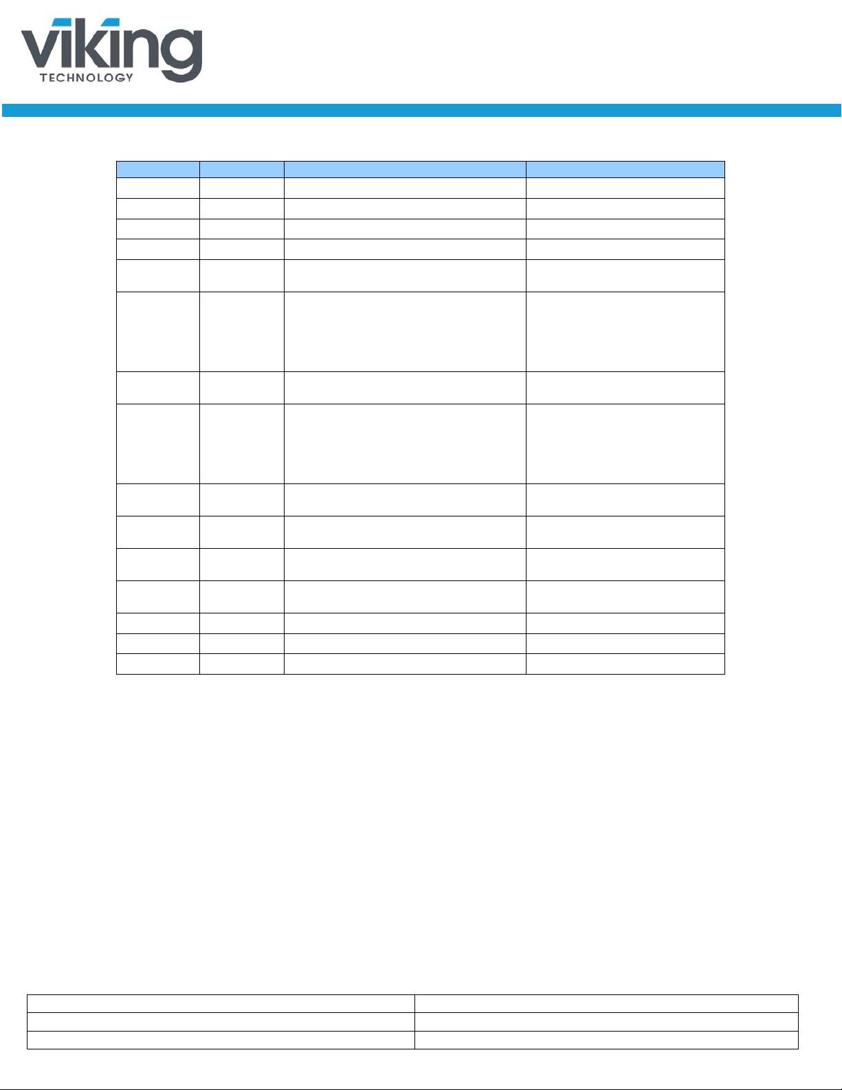
Revision History
Date
Revision
Description
Checked By
Revise SMART table. Added AES
info.
Add product image to 1st page.
Industrial. Added SLC PN’s
Add 3.3V and 5v to block diagram,
voltage table and pin-out
Revised performance #s. Revised
Revise copyright date and product
description
Bob Desmarais
No Connect. Add IOPS data
Add Secure Erase and Military Purge
information
“
4/10/13 X1 Preliminary release
5/10/13 A Initial Release
6/26/13 A1 Fix PN’s
7/11/13 A2 Add Power Consumption
7/24/13 A3
Create separate datasheets for
8/12/13 A4
8/14/13 A5
9/09/13 A6
6Gbps. Revise extended SMART
attributes. Changed Client to
PN table to avoid confusion on Itemperature and commercial
temperature PN’s.
10/22/13 A7
1/15/14 A8
5/15/14 A9
7/24/14 A10
Revised product image
Revise Pinout pin P45 and P47 to
“
www.vikingtechnology.com

Manual
7/24/2014
PSFEM2xxxGRxxx
Viking Technology
Revision A10
Page 3 of 43
Legal Information
Legal Information
Copyright© 2014 Sanmina Corporation. All rights reserved. The information in
this document is proprietary and confidential to Sanm ina Corporation. No part of
this document may be reproduced in any form or by any means or used to make
any derivative work (such as translation, transformation, or adaptation) without
written permission from Sanmina. Sanmina reserves the right to revise this
documentation and to make changes in content from time to time without
obligation on the part of Sanmina to provide notification of such revision or
change.
Sanmina provides this documentation without warranty, term or conditio n of any
kind, either expressed or implied, including, but not limited to, expressed and
implied warranties of merchantability, fitness for a particular purpose, and noninfringement. While the information contained herein is believed to be accurate,
such information is preliminary, and should not be relied upon for accuracy or
completeness, and no representations or warranties of accuracy or
completeness are made. In no event will Sanmina be liable for d amages arising
directly or indirectly from any use of or reliance upon the information contained in
this document. Sanmina may make improvements or changes in the product(s)
and/or the program(s) described in this documentation at any time.
Sanmina, Viking Technology, Viking Modular Solutions, and Element logo are
trademarks of Sanmina Corporation. Other company, pr oduct or service names
mentioned herein may be trademarks or service marks of their respective
owners.
www.vikingtechnology.com
Manual
7/24/2014
PSFEM2xxxGRxxx
Viking Technology
Revision A10
Page 4 of 43
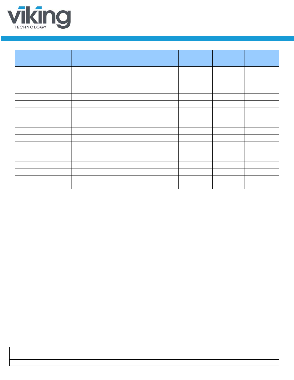
Ordering Information: mSATA SSD Solid-S tat e D ri v e
Raw
(GB)
Useable
(GB)1
Addressable
LBA Mode
Range
Part Numbers
VRFEM2030GRIWMxx 6Gbps Industrial 32 30 58,626,288 MLC -40 to 85c
VRFEM2060GRIYMxx 6Gbps Industrial 64 60 117,231,408 MLC -40 to 85c
VRFEM2120GRITMxx 6Gbps Industrial 128 120 234,441,648 MLC -40 to 85c
VRFEM2030GRCWMxx 6Gbps Industrial 32 30 58,626,288 MLC 0 to 70c
VRFEM2060GRCYMxx 6Gbps Industrial 64 60 117,231,408 MLC 0 to 70c
VRFEM2120GRCTMxx 6Gbps Industrial 128 120 234,441,648 MLC 0 to 70c
VRFEM2240GRCVMxx 6Gbps Industrial 256 240 468,862,128 MLC 0 to 70c
VRFEM2030GRCWExx 6Gbps Industrial 32 30 58,593,750 eMLC 0 to 70c
VRFEM2030GRCYExx 6Gbps Industrial 32 30 58,593,750 eMLC 0 to 70c
VRFEM2060GRCYExx 6Gbps Industrial 64 60 117,231,408 eMLC 0 to 70c
VRFEM2120GRCTExx 6Gbps Industrial 128 120 234,441,648 eMLC 0 to 70c
VRFEM2240GRCVExx 6Gbps Industrial 256 240 468,862,128 eMLC 0 to 70c
VRFEM2030GRCWSxx 6Gbps Industrial 32 30 58,626,288 SLC 0 to 70c
VRFEM2060GRCYSxx 6Gbps Industrial 64 60 117,231,408 SLC 0 to 70c
VRFEM2120GRCTSxx 6Gbps Industrial 128 120 234,441,648 SLC 0 to 70c
VRFEM2030GRIWSxx 6Gbps Industrial 32 30 58,626,288 SLC -40 to 85c
VRFEM2060GRIYSxx 6Gbps Industrial 64 60 117,231,408 SLC -40 to 85c
VRFEM2120GRITSxx 6Gbps Industrial 128 120 234,441,648 SLC -40 to 85c
Notes:
1. Usable ca pacity based on a level of over-provisioning applied to wear leveling, bad sectors, index tables etc.
2. Higher capacity points may be available based on cu stomer application.
Consult your local Viking Field Appl ication Engineer.
3. SSD’s ship unformatted from the factory unless otherwise requested.
4. 1 GB = 1,000,000,000 Byte
5. One Sect or = 512 Byte.
6. xx is a wild card to indicate customer specific opt i ons
SATA
Interface
Application
Capacity
Capacity
Sectors in
NAND
Technology
Temperature
www.vikingtechnology.com
Manual
7/24/2014
PSFEM2xxxGRxxx
Viking Technology
Revision A10
Page 5 of 43
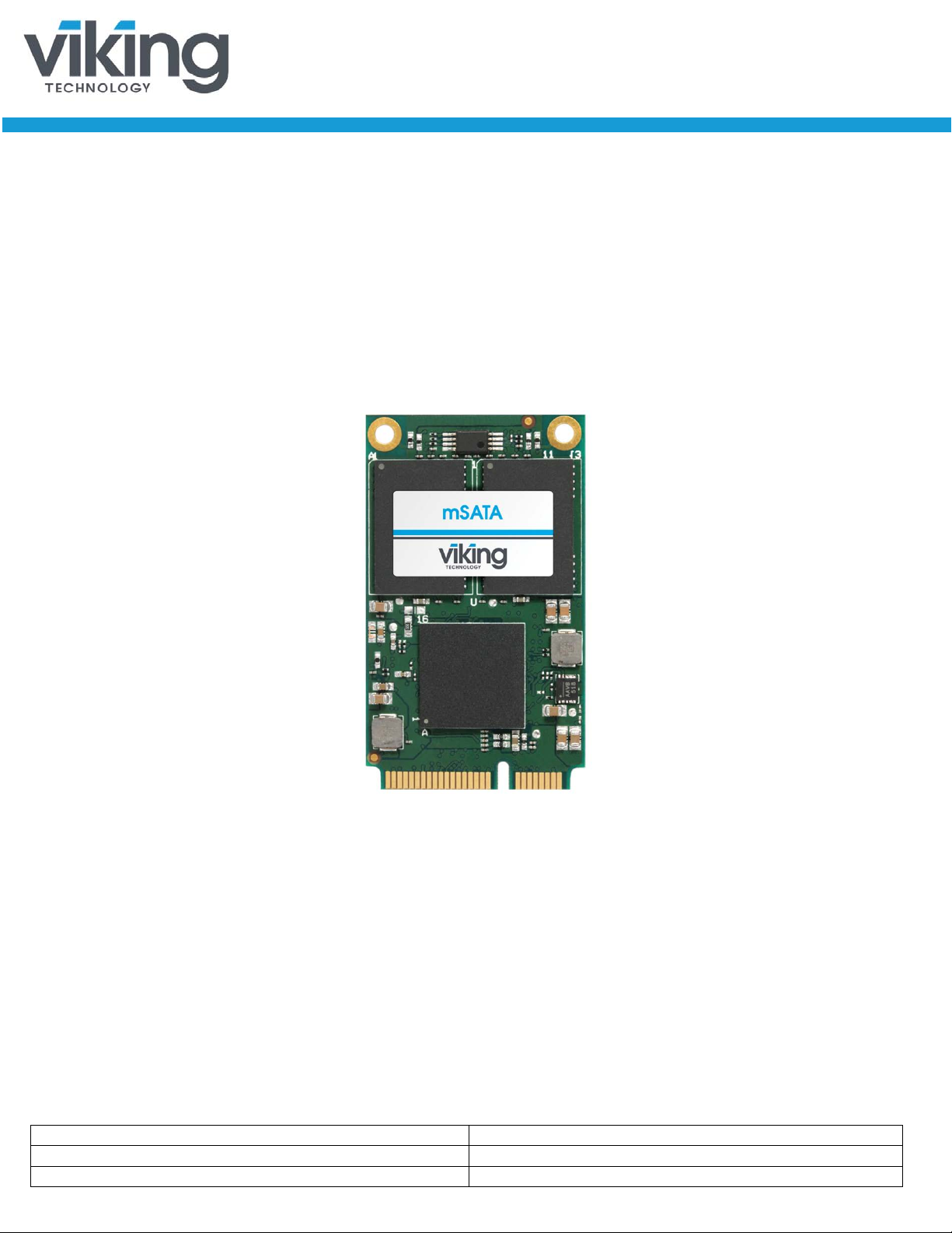
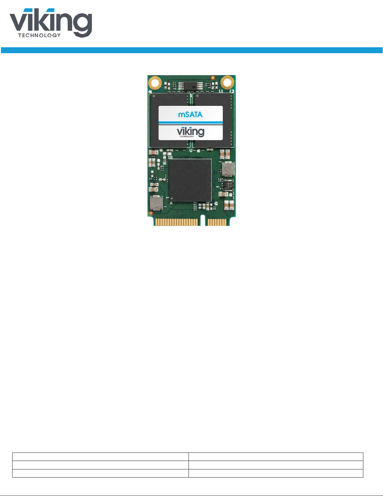
Product Picture(s)
mSATA Top View
www.vikingtechnology.com

Manual
7/24/2014
PSFEM2xxxGRxxx
Viking Technology
Revision A10
Page 6 of 43
Industrial SSD’s – Viking’s Industrial SSD contains sophisticated pr ovisions t o
protect firmware and data from corruption due to unexpected power loss.
However, an Industrial SSD by industry definition does not contain on-board
capacitance. Should power fail unexpectedly, “in-flight” write data may be lost.
Industrial SSD’s are best used in designs that manage power fail events at the
system level.
www.vikingtechnology.com

Manual
7/24/2014
PSFEM2xxxGRxxx
Viking Technology
Revision A10
Page 7 of 43
Table of Contents
1 INTRODUCTION 10
1.1 Features 10
1.2 Block Diagram 11
1.3 SATA Interface 12
2 PRODUCT SPECIFICATIONS 13
2.1 Performance 13
2.2 Timing 13
2.2.1 STANDBY IMMEDIATE Command 13
2.3 Electrical Characteristics 14
2.3.1 Absolute Maximum Ratings 14
2.3.2 Supply Voltage 14
2.3.3 Supply Current 15
2.3.4 Power Consumption 15
2.4 Environmental Conditions 15
2.4.1 Temperature and Altitude 15
2.4.2 Shock and Vibration 16
2.4.3 Electromagnetic Immunity 16
2.5 Reliability 16
2.6 Data Security 16
2.6.1 Quick Erase 17
2.6.2 Military Secure Erase / Sanitization/ Purge Routines 17
3 MECHANI CAL INFORMATION 26
3.1 mSATA SSD Weight 29
4 PIN AND SI GNAL DESCRIPTIONS 29
4.1 Signal and Power Description Tables 29
4.2 Hot Plug Support 30
5 COMMAND SET S 30
www.vikingtechnology.com

Manual
7/24/2014
PSFEM2xxxGRxxx
Viking Technology
Revision A10
Page 8 of 43
5.1 ATA Commands 31
5.1.1 48-Bit Address Command Set 32
5.1.2 ATA General Feature Command Set 32
5.1.3 Device Configuration Overlay Command Set 32
5.1.4 General Purpose Log Command Set 32
5.1.5 Host Protected Area Command Set 33
5.1.6 Power Management Command Set 33
5.1.7 Security Mode Feature Set 33
5.1.8 Identify Device Data 34
5.1.1 S.M.A.R.T. Support 37
5.1.2 SATA 3.0 S.M.A.R.T. Command Set 38
5.2 SATA Commands 41
5.2.1 Native Command Queuing (NCQ) 42
6 REFERENCES 42
7 GLOSSARY 43
www.vikingtechnology.com

Manual
7/24/2014
PSFEM2xxxGRxxx
Viking Technology
Revision A10
Page 9 of 43
Table of Tables
Table 2-1: Maximum Sustained Read and Write Bandwidth ____________________________ 13
Table 2-2: Random Read and Write Input/Out put Operations per Second (IOPS) ___________ 13
Table 2-3: Timing Specifications _________________________________________________ 13
Table 2-4: STANDBY IMMEDIATE Timing _________________________________________ 14
Table 2-5: Absolute Maximum Ratings ____________________________________________ 14
Table 2-6: Operating Voltage ___________________________________________________ 14
Table 2-7: Current Draw _______________________________________________________ 15
Table 2-8: Typical Power Consumption ___________________________________________ 15
Table 2-9: Temperature and Altitude Related Specifications ___________________________ 15
Table 2-10: Shock and Vibration Specifications _____________________________________ 16
Table 2-11: Reliability Specifications ______________________________________________ 16
Table 2-11: Military Secure Erase / Sanit i ze Routines ________________________________ 18
Table 4-1: Mini PCIe Connector Pin Signal Definit i ons ________________________________ 29
Table 5-1: Supported ATA Commands ____________________________________________ 31
Table 5-2: List of Device Identification ____________________________________________ 34
Table 5-3: Capacity specific Device Identifi cat i on ____________________________________ 37
Table 5-4: S.M.A.R.T. Command Set _____________________________________________ 38
Table 5-5: Extended SMART Attribute Table _______________________________________ 38
Table 5-6: Extended SMART Attribute Act ual Dat a ___________________________________ 39
Table 5-7: Supported S.M.A.R.T. EXECUTE OFF-LINE IMMEDIATE Subcommands ________ 41
Table of Figures
Figure 1-1: High-Level Block Diagram ____________________________________________ 11
Figure 3-1: Dimensions ________________________________________________________ 27
www.vikingtechnology.com

Manual
7/24/2014
PSFEM2xxxGRxxx
Viking Technology
Revision A10
Page 10 of 43
1 Introduction
Viking’s rugged industrial designed SSD’s offer the highest flash storage
reliability and performance in harsh environments such as shock, vibration,
humidity, altitude, ESD, and extreme temperatures.
1.1 Features
The SSD delivers the following features:
• Offers seamless SATA Revision 3.0 interface support for SATA up to
6Gb/s
• Low overall SSD power consumption
• Supports Native Command Queuing (NCQ) to 32 commands
• Compatible with all major SLC, MLC and eMLC flash technologies
• S.M.A.R.T.
• Superior wear-leveling algorithm
• Efficient error recovery
www.vikingtechnology.com

Manual
7/24/2014
PSFEM2xxxGRxxx
Viking Technology
Revision A10
Page 11 of 43
1.2 Block Diagram
Figure 1-1: High-Level Block Diagram
Notes:
5V not supported on VRFEM2xxxGRxxxJx PN’s
www.vikingtechnology.com

Manual
7/24/2014
PSFEM2xxxGRxxx
Viking Technology
Revision A10
Page 12 of 43
1.3 SATA Interface
• The Serial ATA (SATA) interface is com pliant with the SATA IO Serial
ATA specification, revision 3.0 that supports SATA up to 6Gb/s.
• The SATA interface connects the host computer to the SSD subsystem.
• The SATA interface runs at a maximum speed of 6 Gbps (Giga-bits per
second). If the host computer is unable to negotiate a speed of 6 Gbps,
the SATA interface automatically renegotiates to a speed of 3 Gbps or 1.5
Gbps.
For a list of supported commands and other specifics, please see Chapter 5.
www.vikingtechnology.com
Manual
7/24/2014
PSFEM2xxxGRxxx
Viking Technology
Revision A10
Page 13 of 43
2 Product Specifications
Access Type
VRFEM2xxxGRxxx
Sequential Read, 256K
Up to 508 MB/s
Sequential Write, 256K
Up to 364 MB/s
Access Type
VRFEM2xxxGRxxx
Read, 4K
Up to 42,500 IOPS
Write, 4K
Up to 1100 IOPS
Type
Average Latency
Power-On-to-Ready (POR)
550 ms
Command to DRQ
600 µsec
6
2.1 Performance
Table 2-1: Maximum Sustained Read and Write Bandwidth
Notes:
1. Performance measured using IOmeter 06 with queue depth set t o 32.
2. Write Cache enabled with DDR cache.
3. Refer to Application Note AN0006 for Viking SSD Benchmar king Methodology.
4. Data is based on SSD’s using Synchronous NAND devices (O N FI or toggle mode)
Table 2-2: Random Read and Write Input/Output Operations per Second
(IOPS)
Notes:
1. Performance measured using Iometer 06 with queue depth set to 32.
2. Write Cache enabled with DDR cache.
3. Random IOPS cover the ent i re range of legal logical block addresses (LBA’s). Measurements are
performed on a full drive (all LBA’s have valid content).
4. Performance may vary by NAND type and host.
5. Refer to Application Note AN0006 for Viking SSD Benchmar king Methodology.
6. Data is based on SSD’s using Synchronous NAND devices (O N FI or toggle mode), i.e 30GB
2.2 Timing
Table 2-3: Timing Specifications
Time to Erase (ATA Secure Erase) 9 sec
Notes:
1. Device measured using Dr i vemaster.
2. Sector Read/Write latency measured up to 2048 block transfers (512B/sector = 1 Block)
3. Queue depth set to 32 for NC Q
4. Sequential IOPS cove r the entire range of legal logical block addresses (LBA’s). Measurements are
performed on a full drive (all LBA’s have valid content
5. DRQ (Data Transfer Requested) bit being asserted
2.2.1 STANDBY IMMEDIATE Command
The Power-On-to-Ready time assumes a proper shutdown (power removal
preceded by STANDBY IMMEDIATE comman d. A STANDBY IMMEDIATE
before power down always performs a graceful shutdown and does not require
www.vikingtechnology.com
 Loading...