

Viking Technology PSFEM1XXXGPXXX User Manual
Manual
6/12/2014
PSFEM1XXXGPXXX
Viking Technology
Revision B4
Page 1 of 48
SATA 6Gb/s
Industrial
Slim SATA
Manual
Slim SATA is a non-volatile, solid-state storage device. With its Serial ATA interface
and Slim SATA (MO-297) form factor, it is a drop in replacemen t for hard disk drives.
Slim SATA delivers extremely high levels of perfor m ance, r eliability and ruggedness for
I/O intensive or environmentally challenging applications.
www.vikingtechnology.com
Manual
6/12/2014
PSFEM1XXXGPXXX
Viking Technology
Revision B4
Page 2 of 48
Revision History
Date
Revision
Description
Initial release of product datasheet where first generation
products were removed.
1/14/13 A
6/14/13 B1 Update SMART attribute to Worst=1
9/14/13 B2 Revised PN table
10/30/13 B3 Added notes on Operating Temperature (TOPER).
1/2/14 B4 Update datasheet format
6/12/14 B4 Rename file from PSFEM1XXXGXXXX to PSFEM1XXXGPXXX
www.vikingtechnology.com

Manual
6/12/2014
PSFEM1XXXGPXXX
Viking Technology
Revision B4
Page 3 of 48
Legal Information
Legal Information
Copyright© 2014 Sanmina Corporation. All rights reserved. The information in
this document is proprietary and confidential to Sanm ina Corporation. No part of
this document may be reproduced in any form or by any means or used to make
any derivative work (such as translation, transformation, or adaptation) without
written permission from Sanmina. Sanmina reserves the right to revise this
documentation and to make changes in content from time to time without
obligation on the part of Sanmina to provide notification of such revision or
change.
Sanmina provides this documentation without warranty, term or conditio n of any
kind, either expressed or implied, including, but not limited to, expressed and
implied warranties of merchantability, fitness for a particular purpose, and noninfringement. While the information contained herein is believed to be accurate,
such information is preliminary, and should not be relied upon for accuracy or
completeness, and no representations or warranties of accuracy or
completeness are made. In no event will Sanmina be liable for d amages arising
directly or indirectly from any use of or reliance upon the information contained in
this document. Sanmina may make improvements or changes in the product(s)
and/or the program(s) described in this documentation at any time.
Sanmina, Viking Technology, Viking Modular Solutions, and the Viking logo are
trademarks of Sanmina Corporation. Other company, pr oduct or service names
mentioned herein may be trademarks or service marks of their respective
owners.
Export Control
Sanmina, Viking Technology must ensure that our customers understand that our
family of Solid-State Drives (SSD) are subject to US export control restrictions. In
summary, our products cannot be exported or re-exported to any foreign
government; and their use in the design, development, production or use of
nuclear, chemical or biological weapons or missiles r equires a separate license
for export or re-export. They also may not be exported or re-exported to Cuba,
Iran, North Korea, Sudan or Syria.
www.vikingtechnology.com
Manual
6/12/2014
PSFEM1XXXGPXXX
Viking Technology
Revision B4
Page 4 of 48
Ordering Information: Slim SATA SSD Solid-State Drive
LBA Mode
Minimum
Raw
Capacity
(GB)
Part Number
SATA
Interface
Application
VRFEM1008GPCxMyz 6Gbps Industrial 16 8 15,649,200 MLC 0 to 70°C
VRFEM1012GPCxMyz 6Gbps Industrial 16 12 31,277,232 MLC 0 to 70°C
VRFEM1025GPCxMyz 6Gbps Industrial 32 25 48,858,768 MLC 0 to 70°C
VRFEM1032GPCxMyz 6Gbps Industrial 48 32 62,533,296 MLC 0 to 70°C
VRFEM1055GPCxMyz 6Gbps Industrial 64 55 107,463,888 MLC 0 to 70°C
VRFEM1080GPCxMyz 6Gbps Industrial 128 80 156,301,488 MLC 0 to 70°C
VRFEM1120GPCxMyz 6Gbps Industrial 128 120 234,441,648 MLC 0 to 70°C
Notes:
1) Usable capacity based on a level of over-provisioning applied to wear leveling, bad sectors, index tables etc.
2) Higher capacity points may be available based on customer applicatio n. Consult your local Viking FAE.
3) SSD’s ship unformatted from the factory unless otherwise requested.
4) x = Lowercase character(s) for device d ensity. Contact Viking for the chara cter that “x” represents in the part number.
5) y and z = Lowercase character(s) for NA ND ve ndor and die revisions and/or for customer specific locked BOM’s
6) 1 GB = 1,000,000,000 Byte and not all of the memory can be used for data storage. Usable capacity
based on over-provisioning applied to wear leveling, bad sectors, index tables etc.
7) 1 Sector = 512 Byte.
Useable
Capacity
(GB)1
Total User
Addressable
Sectors in
NAND
Technology
Temperature
Range
www.vikingtechnology.com

Manual
6/12/2014
PSFEM1XXXGPXXX
Viking Technology
Revision B4
Page 5 of 48
Industrial SSD – Viking’s Industrial SSD contains sophisticated provisio ns to
protect firmware and data from corruption due to unexpected power loss.
However, a Industrial SSD by industry definition does not contain on-board
capacitance. Should power fail unexpectedly, “in-flight” write data m ay be lost.
Industrial SSD’s are best used in designs that manage power fail events at the
system level.
www.vikingtechnology.com
Manual
6/12/2014
PSFEM1XXXGPXXX
Viking Technology
Revision B4
Page 6 of 48
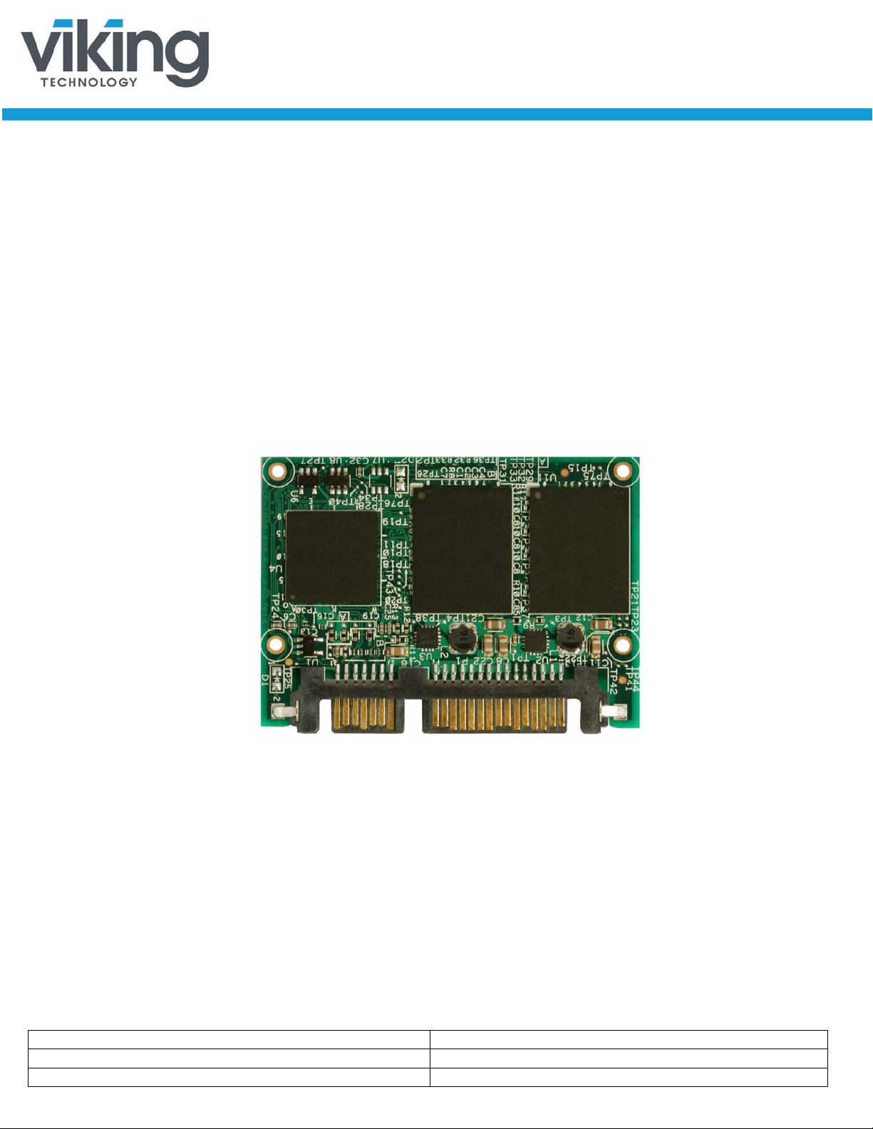
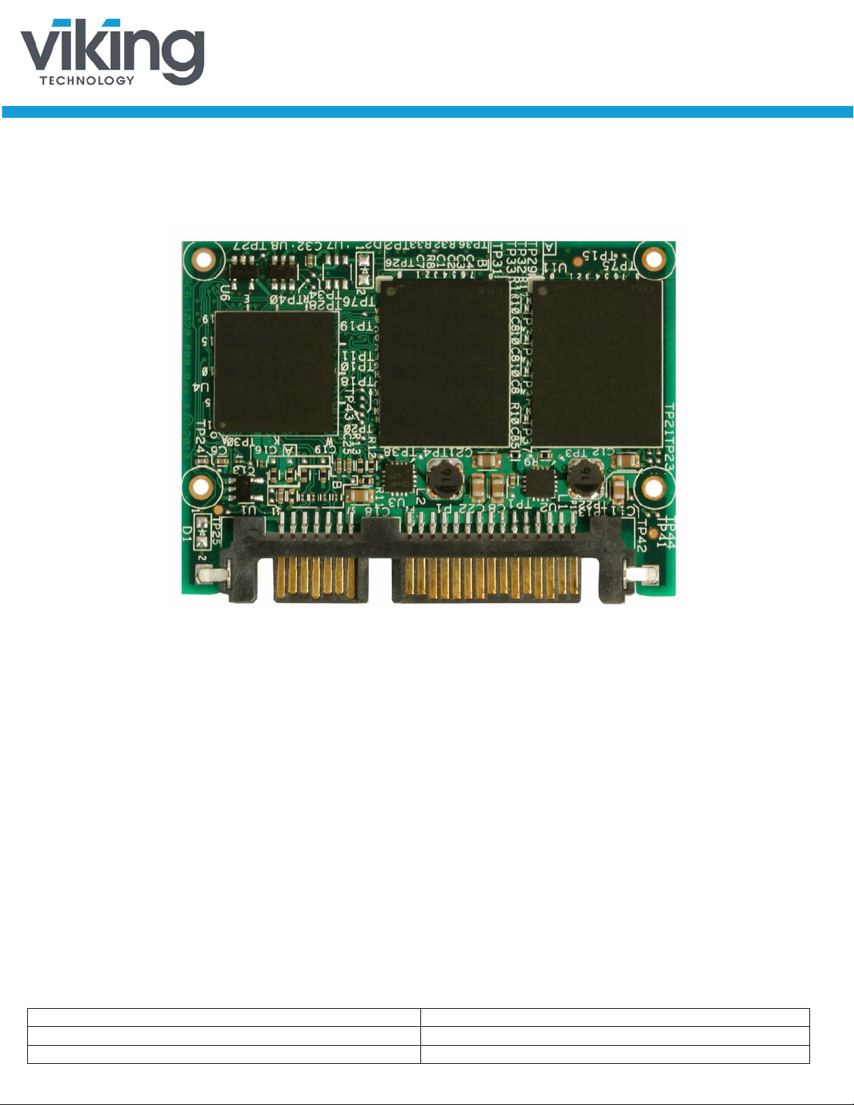
Product Picture(s)
Slim SATA Top View
www.vikingtechnology.com

Manual
6/12/2014
PSFEM1XXXGPXXX
Viking Technology
Revision B4
Page 7 of 48
Table of Contents
1 INTRODUCTION 10
1.1 Features 10
1.2 Block Diagram 12
1.3 SATA Interface for VRFEM1xxxGP 13
1.4 Indicator LEDs 13
2 PRODUCT SPECIFICATIONS 13
2.1 Performance 13
2.2 Timing 14
2.2.1 STANDBY IMMEDIATE Command 14
2.3 Electrical Characteristics 15
2.3.1 Absolute Maximum Ratings 15
2.3.2 Supply Voltage 15
2.3.3 Supply Current 15
2.3.4 Power Consumption 16
2.4 Environmental Conditions 16
2.4.1 Temperature and Altitude 16
2.4.2 Shock and Vibration 16
2.4.3 Electromagnetic Immunity 17
2.5 Reliability 17
2.5.1 Data, MetaData, and Firmware Code Protection 17
2.5.2 Intelligent Read Disturb Management 19
2.5.3 Intelligent Write Operation Management 19
2.6 Data Security 20
3 MECHANICAL INFORMATION 21
3.1 Slim SATA SSD Weight 22
4 PIN AND SIGNAL DESCRIPTIONS 22
4.1 Pin Locations 22
4.2 Signal and Power Description Tables 22
www.vikingtechnology.com

Manual
6/12/2014
PSFEM1XXXGPXXX
Viking Technology
Revision B4
Page 8 of 48
4.3 Hot Plug Support 23
5 COMMAND SETS 24
5.1 ATA Commands 26
5.1.1 48-Bit Address Command Set 29
5.1.2 ATA General Feature Command Set 29
5.1.3 Device Configuration Overlay Command Set 30
5.1.4 General Purpose Log Command Set 30
5.1.5 Host Protected Area Command Set 30
5.1.6 Power Management Command Set 31
5.1.7 Security Mode Feature Set 31
5.1.1 S.M.A.R.T. Support 31
5.1.2 S.M.A.R.T. Command Set 32
5.1.3 S.M.A.R.T. Attributes 34
5.1.4 Threshold Sector 45
5.1.5 S.M.A.R.T. Command Transport (SCT) 46
5.2 SATA Commands 46
5.2.1 Native Command Queuing (NCQ) 46
6 CERTIFICATIONS AND COMPLIANCE 47
7 REFERENCES 47
8 GLOSSARY 48
www.vikingtechnology.com

Manual
6/12/2014
PSFEM1XXXGPXXX
Viking Technology
Revision B4
Page 9 of 48
Table of Tables
Table 1-1: Slim SATA SSD Features _____________________________________________ 10
Table 2-1: Maximum Sustained Read and Write: MB/sec and IOPS _____________________ 14
Table 2-2: Timing Specifications _________________________________________________ 14
Table 2-3: STANDBY IMMEDIATE Timings ________________________________________ 14
Table 2-4: Absolute Maximum Ratings ____________________________________________ 15
Table 2-5: Operating Voltage ___________________________________________________ 15
Table 2-6: Current Draw _______________________________________________________ 15
Table 2-7: Typical Power Consumption ___________________________________________ 16
Table 2-8: Temperature and Altitude Related Specifications ___________________________ 16
Table 2-9: Shock and Vibration Specifications ______________________________________ 17
Table 2-10: Reliability Specifications ______________________________________________ 17
Table 4-1: Serial ATA Connector Pin Signal Definiti ons _______________________________ 22
Table 4-2: Serial ATA Power Pin Definitions ________________________________________ 23
Table 5-1: ATA Feature Set ____________________________________________________ 24
Table 5-2: ATA Commands _____________________________________________________ 26
Table 5-3: S.M.A.R.T. Command Set _____________________________________________ 32
Table 5-4: Supported S.M.A.R.T. EXECUTE OFF-LINE IMMEDIATE Subcommands ________ 32
Table 5-5: Baseline S.M.A.R.T. Attribute Summary __________________________________ 34
Table 5-6: Baseline S.M.A.R.T. Attribute Details _____________________________________ 36
Table 5-7: S.M.A.R.T. Attribute Data Structure ______________________________________ 45
Table 5-8: S.M.A.R.T. Threshold Data Structure _____________________________________ 46
Table 6-1: Device Certifications _________________________________________________ 47
Table of Figures
Figure 1-1: High-Level Block Diagram for VRFEM1xxP _______________________________ 12
Figure 3-1: Dimensions ________________________________________________________ 21
Figure 4-1: Layout of Signal and Power Segment Pins ________________________________ 22
Figure 5-1: S.M.A.R.T. ECC and RAISE Error Summary ______________________________ 44
www.vikingtechnology.com
Manual
6/12/2014
PSFEM1XXXGPXXX
Viking Technology
Revision B4
Page 10 of 48
1 Introduction
•
•
•
Power hold-up circuit technology ensures no data loss resulting from an unexpected
power loss and is supported for industrial temperatures (requires host provisions)
•
•
•
•
•
•
•
Viking’s rugged designed SSD’s offer the highest flash storage reliability and
performance in harsh environments such as shock, vibration, humidity, altitude,
ESD, and extreme temperatures. Viking SSD’s meet JEDEC JESD22 standards
and pass numerous qualifications including MIL-STDs and NEBS.
Viking can also provide specialized services to OEMs designing customized
hardware and systems by offering:
• Locked BOM control with customer product change notification (PCN)
• Pre-installed software, custom software imaging and ID strings
• Custom packaging and labeling
• Comprehensive supply-chain management
• Customer specified testing
• 30K volt ESD protection
• Conformal coating
• Localized Field Application Engineering for complete pre and post sale
technical support
1.1 Features
Table 1-1: Slim SATA SSD Features
The Slim SATA SSD delivers the following features:
Feature VRFEM1xxxGP
Best in class sequential and random Read/Write performance
Seamless SATA Revision 2.x interface support for SATA up to 3Gbps)
Seamless SATA Revision 3.x interface support for SATA up to 6Gbps)
PFAIL/DHARD signaling with the host
Support for ONFi and Toggle Mode NAND
Patented architecture for SSD longevity, reliability and data integrity
Supports Native Command Queuing (NCQ) to 32 commands
Native support for 512 and non-512 host LBA sizes
Automatic Trim Command support
Compatible with all major SLC and MLC NAND flash technologies
Protection against catastrophic flash page and block failures
www.vikingtechnology.com
Manual
6/12/2014
PSFEM1XXXGPXXX
Viking Technology
Revision B4
Page 11 of 48
Feature VRFEM1xxxGP
AES-128 encryption in CTR mode
•
•
Superior wear-leveling algorithm
•
•
Efficient error recovery
•
•
Thermal sensing energy management
•
•
S.M.A.R.T. command transport (SCT) technology
Intelligent flash memory block management and read disturb management
Power-throttling support
RoHS and WEEE compliant
www.vikingtechnology.com
Manual
6/12/2014
PSFEM1XXXGPXXX
Viking Technology
Revision B4
Page 12 of 48
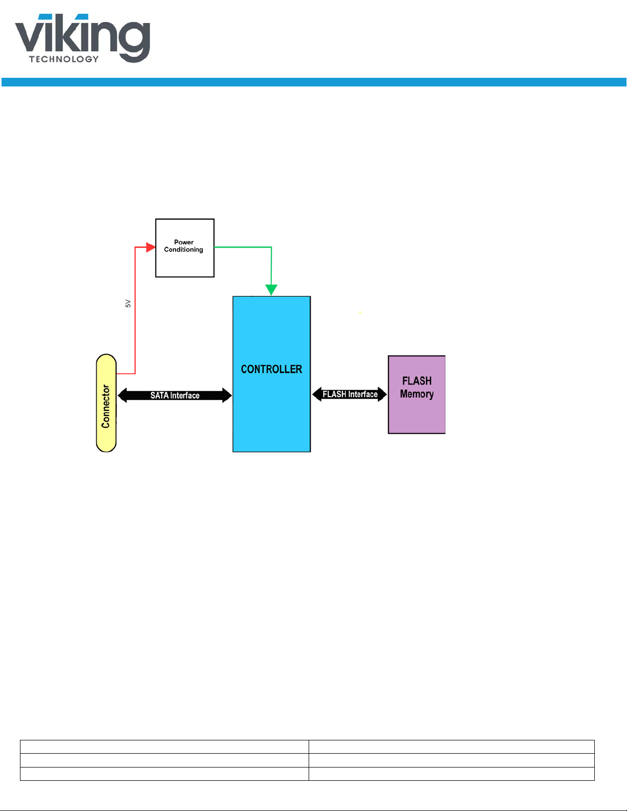
1.2 Block Diagram
Figure 1-1: High-Level Block Diagram for VRFEM1xxP
www.vikingtechnology.com

Manual
6/12/2014
PSFEM1XXXGPXXX
Viking Technology
Revision B4
Page 13 of 48
1.3 SATA Interface for VRFEM1xxxGP
• The Serial ATA (SATA) interface is compliant with the SATA IO Serial
ATA specification, revision 3.x that supports SATA up to 6Gbps.
• The SATA interface connects the host computer to the SSD subsystem.
• The SATA interface runs at a maximum speed of 6.0Gbps (Gigabits per
second). If the host computer is unable to negotiate a speed of 6.0Gbps,
the SATA interface automatically renegotiates to a speed of 3.0 or 1.5
Gbps.
For a list of supported commands and other specifics, please see Chapter 5.
1.4 Indicator LEDs
There is an optional LED indicator on the Slim SATA module that will flash to
indicate an SATA activity condition. There is also a remote LED indicator at Pin
11 of the Power Segment Connector, called “Device Activity Signal”. For a
remote LED application, an LED should be tied high through a current limiting
resistor on the host side. The Slim SATA will sink current on the module to allow
the LED to flash to indicate an ACTIVITY. If a remote LED is not implemented,
pin 11 may be connected to GND to allow the ACTIVITY LED to remain on and
indicate a Power On condition when using a standard ATX type power supply.
2 Product Specifications
2.1 Performance
Maximum SSD performance can be achieved for certain workloads by:
• Initiating read and write transfers for random accesses with small block
sizes of 4K bytes to optimize IOPs performance for applications such as
databases, OLTP etc.
• Initiating read and write transfers for sequential accesses with large blocks
(128K or larger) to optimize performance toward throughput (MBps) for
applications such as video streaming, data acquisition etc.
• Issuing transfers at starting LBA’s which align the access on 4K
boundaries:
o Minimizes or eliminates internal Read-Modify-Write operations
o Align on 4K boundaries is optimal for SSD capacities up to 256 GB
o For SSD capacities greater than 256 GB, aligning on 8K
boundaries is optimal
• Avoid mixing NCQ and non-NCQ commands
www.vikingtechnology.com
Manual
6/12/2014
PSFEM1XXXGPXXX
Viking Technology
Revision B4
Page 14 of 48
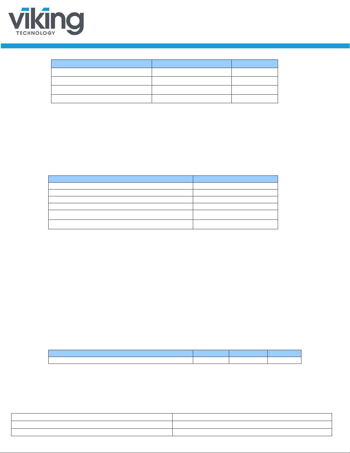
Table 2-1: Maximum Sustained Read and Write: MB/sec and IOPS
Type
Average Latency or Timing
Power-On-to-Ready (POR)
115 ms
Reset to Ready
115 ms
Sleep to Ready
<1000 μs
Command to DRQ
<1000 μs
Time to Erase (ATA Secure Erase)
4 seconds
Time to Erase (ATA Secure Erase with flash erase)
~ 1 GB/second
Power Cycle Endurance
Min
Max
Unit
STANDBY IMMEDIATE to WE completed
15
25
ms
Access Type VRFEM1xxxGP Units
Sequential Read, 128K block size Up to 500 MB/s
Sequential Write, 128K block size Up to 500 MB/s
Random Read, 4K block size Up to 60,000 IOPS
Random Write, 4K block size Up to 20,000 IOPS
Notes:
1. Performance measured using IOmeter 08 with queue depth set to 32.
2. Write Cache enabled.
3. Random IOPS cover the entire range of legal logical block addresses (LBA’s). Measurements are
performed on a full drive (all LBA’s have valid content).
4. Performance may vary by NAND type and host.
5. Refer to Application Note AN0006 for Viking SSD B enchmarking Methodology.
2.2 Timing
Table 2-2: Timing Specifications
Notes:
1. Based on MLC
2. Device measured using Drivemaster.
3. Sector Read/Write latency measured up to 2048 block transfers (512B/sector = 1 Block)
4. Queue depth set to 32 for NCQ
5. Sequential I OPS cover the entire range of legal logical block addresses (LBA’s). M easu rements are
performed on a full drive (all LBA’s have valid content
2.2.1 STANDBY IMMEDIATE Command
The Power On to Ready time assumes a proper shutdown (power removal
preceded by STANDBY IMMEDIATE comman d. A STANDBY IMMEDIATE
before power down always performs a graceful shutdown and does not require
the use of the hold-up circuit. Note that SMART attribute 174 "Unexpected Power
Loss" records the number of non-graceful power cycle events.
Table 2-3: STANDBY IMMEDIATE Timings
www.vikingtechnology.com
Manual
6/12/2014
PSFEM1XXXGPXXX
Viking Technology
Revision B4
Page 15 of 48
2.3 Electrical Characteristics
Description
Min
Max
Unit
Maximum Voltage Range for Vin
-0.2 6 V
Maximum Temperature Range
-40
85
c
Description
Min
Max
Unit
Operating Voltage for 5.0 V (+/- 10%)
4.5
5.5
V
Peak
600
mA
Idle
<80
mA
2.3.1 Absolute Maximum Ratings
Values shown are stress ratings only. Functional operation outside normal
operating values is not implied. Extended exposure to absolute maximum ratings
may affect reliability.
Table 2-4: Absolute Maximum Ratings
2.3.2 Supply Voltage
The operating voltage is 5.0V.
Table 2-5: Operating Voltage
2.3.3 Supply Current
Table 2-6: Current Draw
Mode
Read/Writes 400 mA
Notes:
1. Typical power workload: 16K block size, 50% read, 50% sequential write. Maximum power workload:
256K block size, 0% read, 100% sequential write.
2. Table values based on 100GB drive.
VRFEM1xxxGPxx1
Unit
www.vikingtechnology.com
 Loading...