

Viking Technology PSF1XXXXGXXXX User Manual
Manual
1/2/2014
PSFS1XXXXGXXXX
Viking Technology
Revision B7
Page 1 of 60
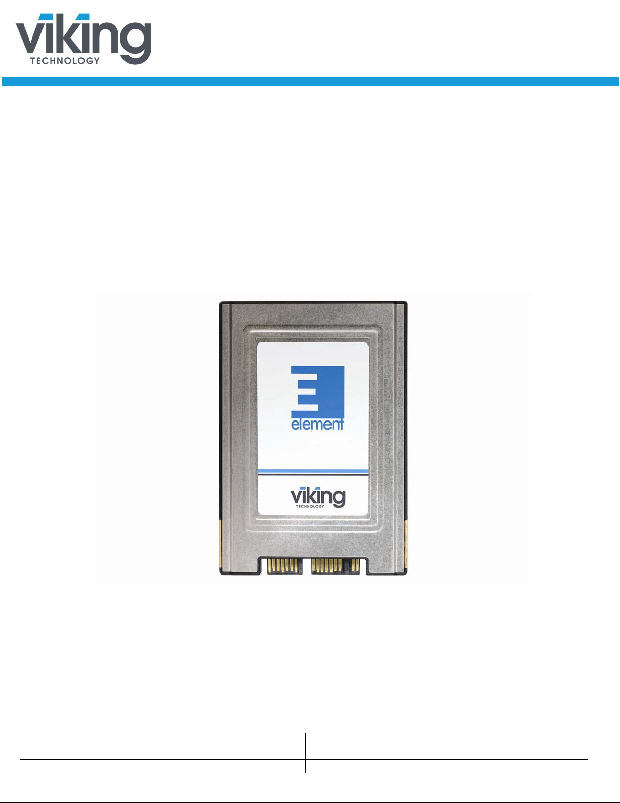
The SATA Element SSD is a non-volatile, solid-state storage device. With its
Serial ATA interface and industry-standard form factors, it is a drop in
replacement for hard disk drives. The Element SSD deliver s extremely high levels
of performance, reliability and ruggedness for I/O intensive or environmentally
challenging applications.
SATA 6Gb/s
1.8” SSD
Manual
www.vikingtechnology.com
Manual
1/2/2014
PSFS1XXXXGXXXX
Viking Technology
Revision B7
Page 2 of 60
Date
Revision
Description
Checked by
3/26/12
A
Release of new format. Changed supply
Immediate Standby timings.
5/01/12
A1
Added part number VRFS11240GFCyMz.
VRFxxGJxx. Add mass/weight of SSD.
6/05/12
A2
Added note on enterprise vs client
6/07/12
A3
attributes. Added note on enterprise vs client
9/27/12
A4
Update PN table to VT PSGC 9.18.12. Added
Added performance for xxGK and xxKM
10/17/12
A5
Added performance for xxGK and xxKM
4/9/13
B
Update Company name. Added xxTJxx P N ’s
4/19/13
B1
Add power consumption informat ion (based on
VRFS11480GMCVMTHP1, VRFS11400GFCVETHE1)
6/19/13
B2
Remove xxxGMxx from PN table due to
xxxGFxxx feature table
7/17/13
B3
VRFS11100GFITM. Revised
9/12/13
B5
Revised PN Table
Revision History
voltage to +/-5%. Deleted part numbers
VRFS11100GAIPSTF (1.8”). Added notes
for operating temperature. Updated
SMART attribute table. Corrected SMART
threshold table. Added “Ambient” to
temperature range, Added info on
Revised mechanical drawing and SMA R T
attributes. Revised the attributes for
Added note features not available f or i ndustrial
versions, which are VRFS1xGA, VRFS1xGK
and VRFS1xGM. Added a note on SMART
Capacity LBA table. Adjusted indentation.
Changed altitude specification and add
note on storage temperature
Removed all PN’s with an “A" or a “B” in
the controller location of the part number in
the Order Information table
Add more detail to Block diagram, added
current and power tables for 480GB drive.
Added VRFS11025GFIRSTH and
VRFS11050GFIRSTH to PN table along
with config #’s.
client and enterprise SSD’s ( ie:
controller going EOL. Add low power mode in
Added
SMART attributes to worst=1
8/22/13 B4
www.vikingtechnology.com
Revised the weight for client and ent er prise
SSD’s. add photo to 1
st
page
Manual
1/2/2014
PSFS1XXXXGXXXX
Viking Technology
Revision B7
Page 3 of 60
Date
Revision
Description
Checked by
10/22/13
B6
Revised description of SMART Attribute 13
(Soft read error rate)
1/2/14
B7
Updated datasheet format
Bob Desmarais
www.vikingtechnology.com

Manual
1/2/2014
PSFS1XXXXGXXXX
Viking Technology
Revision B7
Page 4 of 60
Legal Information
Legal Information
Copyright© 2014 Sanmina Corporation. All rights reserved. The information in
this document is proprietary and confidential to Sanm ina Corporation. No part of
this document may be reproduced in any form or by any means or used to make
any derivative work (such as translation, transformation, or adaptation) without
written permission from Sanmina. Sanmina reserves the right to revise this
documentation and to make changes in content from time to time without
obligation on the part of Sanmina to provide notification of such revision or
change.
Sanmina provides this documentation without warranty, term or conditio n of any
kind, either expressed or implied, including, but not limited to, expressed and
implied warranties of merchantability, fitness for a particular purpose, and noninfringement. While the information contained herein is believed to be accurate,
such information is preliminary, and should not be relied upon for accuracy or
completeness, and no representations or warranties of accuracy or
completeness are made. In no event will Sanmina be liable for d amages arising
directly or indirectly from any use of or reliance upon the information contained in
this document. Sanmina may make improvements or changes in the product(s)
and/or the program(s) described in this documentation at any time.
Sanmina, Viking Technology, Viking Modular Solutions, and the Viking logo are
trademarks of Sanmina Corporation. Other company, pr oduct or service names
mentioned herein may be trademarks or service marks of their respective
owners.
Export Control
Sanmina, Viking Technology must ensure that our custom er s under stand that our
family of Solid-State Drives (SSD) are subject to US export contr ol restrictions. I n
summary, our products cannot be exported or re-exported to any foreign
government; and their use in the design, development, production or use of
nuclear, chemical or biological weapons or missiles r equires a separate license
for export or re-export. They also may not be exported or re-exported to Cuba,
Iran, North Korea, Sudan or Syria.
www.vikingtechnology.com
Manual
1/2/2014
PSFS1XXXXGXXXX
Viking Technology
Revision B7
Page 5 of 60
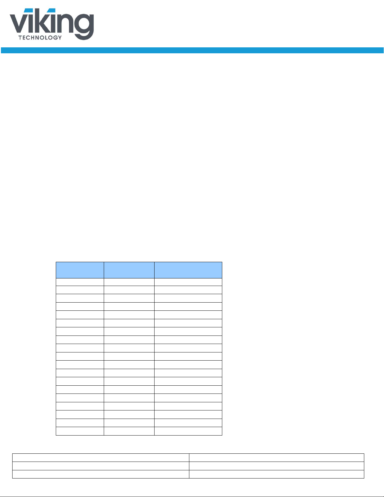
Part Number
Form Factor
Temperature
type
Capacity
Platform
Interface
VRFS11100GFCxMyz
SSD 1.8” 5.0mm
Com (0 to +70 ºC)
MLC
100GB
Enterprise
SATA 6Gb
VRFS11100GFCxMyz
SSD 1.8” 5.0mm
Com (0 to +70 ºC)
MLC
100GB
Enterprise
SATA 6Gb
VRFS11200GFCxMyz
SSD 1.8” 5.0mm
Com (0 to +70 ºC)
MLC
200GB
Enterprise
SATA 6Gb
VRFS11200GFCxMyz
SSD 1.8” 5.0mm
Com (0 to +70 ºC)
MLC
200GB
Enterprise
SATA 6Gb
VRFS11400GFCxMyz
SSD 1.8” 5.0mm
Com (0 to +70 ºC)
MLC
400GB
Enterprise
SATA 6Gb
VRFS11400GFCxMyz
SSD 1.8” 5.0mm
Com (0 to +70 ºC)
MLC
400GB
Enterprise
SATA 6Gb
VRFS11100GFCxEyz
SSD 1.8” 5.0mm
Com (0 to +70 ºC)
eMLC
100GB
Enterprise
SATA 6Gb
VRFS11200GFCxEyz
SSD 1.8” 5.0mm
Com (0 to +70 ºC)
eMLC
200GB
Enterprise
SATA 6Gb
VRFS11400GFCxEyz
SSD 1.8” 5.0mm
Com (0 to +70 ºC)
eMLC
400GB
Enterprise
SATA 6Gb
VRFS11025GFCxSyz
SSD 1.8” 5.0mm
Com (0 to +70 ºC)
SLC
25GB
Enterprise
SATA 6Gb
VRFS11050GFCxSyz
SSD 1.8” 5.0mm
Com (0 to +70 ºC)
SLC
50GB
Enterprise
SATA 6Gb
VRFS11100GFCxSyz
SSD 1.8” 5.0mm
Com (0 to +70 ºC)
SLC
100GB
Enterprise
SATA 6Gb
VRFS11025GFIxSyz8
SSD 1.8” 5.0mm
Ind (-40 to +85 ºC)
SLC
25GB
Enterprise
SATA 6Gb
VRFS11050GFIxSyz8
SSD 1.8” 5.0mm
Ind (-40 to +85 ºC)
SLC
50GB
Enterprise
SATA 6Gb
VRFS11100GFIxMyz
SSD 1.8” 5.0mm
Ind (-40 to +85 ºC)
MLC
120GB
Enterprise
SATA 6Gb
VRFS11120GFIxMyz
SSD 1.8” 5.0mm
Ind (-40 to +85 ºC)
MLC
120GB
Enterprise
SATA 6Gb
VRFS11240GFIxMyz
SSD 1.8” 5.0mm
Ind (-40 to +85 ºC)
MLC
240GB
Enterprise
SATA 6Gb
VRFS11240GKIxMyz
SSD 1.8” 5.0mm
Ind (-40 to +85 ºC)
MLC
240GB
Client
SATA 6Gb
Ordering Information: Element 1.8” SSD Family
Viking High Performance Solid-State Drive Or der ing I nformation
NAND
User
VRFS11120GKIxMyz SSD 1.8” 5.0mm Ind (-40 to +85 ºC) MLC 120GB Client SATA 6Gb
Notes:
1) Usable capacity based on a level of over-provisioning applied to wear leveling, bad sectors, index tables etc.
2) Higher capacity points may be available based on customer applicat i on. Consult your local Viking Field Application
Engineer.
3) SSD’s ship unformatted from the factory unless otherwise requested.
4) x= Lowercase character(s) for NAND capacity. Contact Viking for what “x” represents in the PN.
5) y and z = Lowercase character(s) for NAND vendor and die revisions and /or for customer specific locked BOMs
6) 1 GB = 1,000,000,000 Byte and not all of the memory can be used for data storage. Usa ble capacity
7) 1Sector = 512 Byte.
8) VRFS11025GFIRSTH config ID=25287, VRFS11050GFIRSTH config ID =25307
www.vikingtechnology.com

Manual
1/2/2014
PSFS1XXXXGXXXX
Viking Technology
Revision B7
Page 6 of 60
Viking’s solid state drives are available in Enterprise and Client versions:
Enterprise SSD – An Enterprise SSD contains hardware and firmware that
detect and manage power failures. This allows the drive to flush the controller
cache and harden data to NAND flash. No data is lost or corrupted.
Client SSD – A Client SSD does not include power failure detection or
management features. MLC NAND, as opposed to SLC NAND, can become
corrupted if power is removed during a write, also known as lower page
corruption. Therefore, a Client SSD using MLC NAND is we ll-suited in a system
that already manages power fail events, allowing for graceful SSD shutdown.
Accordingly, system support should include issuing a Standby Immediate
command to the SSD while maintaining power for at least 50ms.
If a Client drive with MLC NAND is used in a system that does not manage power
failures and shutdowns, there is a small chance of data corruption. Viking Clie n t
SSD’s take sophisticated hardware and firmware measures to prevent or mitigate
such issues making the chance of corruption very small.
If the SSD controller detects data corruption, the drive will be locked. The only
way to recover the drive is to return it to the factory for reprogramming; all data
will be lost.
www.vikingtechnology.com
Manual
1/2/2014
PSFS1XXXXGXXXX
Viking Technology
Revision B7
Page 7 of 60
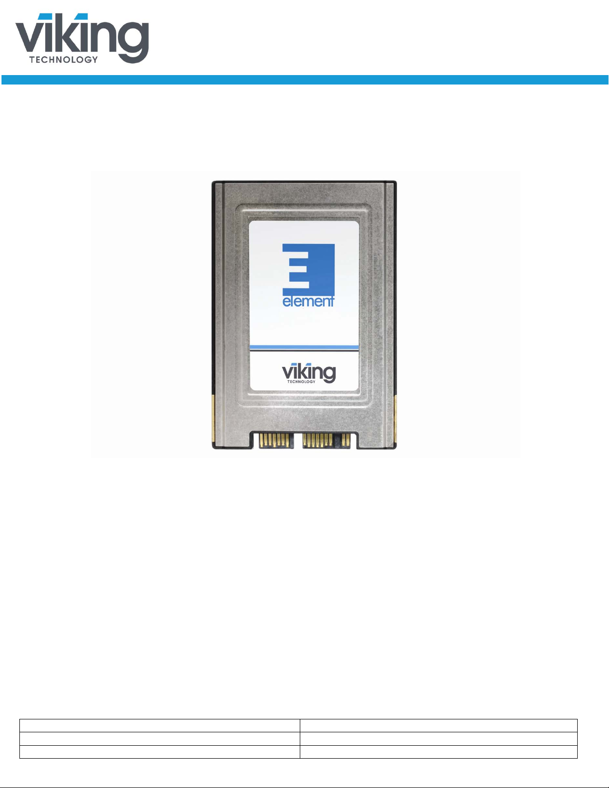
Product Picture(s)
www.vikingtechnology.com

Manual
1/2/2014
PSFS1XXXXGXXXX
Viking Technology
Revision B7
Page 8 of 60
Table of Contents
1 INTRODUCTION 11
1.1 Features 11
1.2 Block Diagram 14
1.3 SATA Interface for VRFS1xGA, VRFS1xGJ 15
1.4 SATA Interface for VRFS1xGF, VRFS1xGK, VRFS1xGM 15
2 PRODUCT SPECIFICATIONS 15
2.1 Capacity-LBA 15
2.2 Performance 16
2.3 Timing 18
2.3.1 STANDBY IMMEDIATE Command 18
2.4 Electrical Characteristics 19
2.4.1 Absolute Maximum Ratings 19
2.4.2 Supply Voltage 19
2.4.3 Supply Current 19
2.4.4 Power Consumption 19
2.5 Environmental Conditions 20
2.5.1 Temperature and Altitude 20
2.5.2 Shock and Vibration 21
2.5.3 Electromagnetic Compatibility 21
2.6 Reliability 22
2.6.1 Data, MetaData, and Firmware Code Protection 22
2.6.2 Intelligent Read Disturb Management 24
2.6.3 Intelligent Write Operation Management 24
2.7 Data Security 25
2.7.1 Secure Erase Support 26
3 MECHANICAL INFORMATION 28
3.1 Element SSD Physical Dimensions 28
3.2 Element SSD Weight 29
4 PIN AND SIGNAL DESCRIPTIONS 29
www.vikingtechnology.com

Manual
1/2/2014
PSFS1XXXXGXXXX
Viking Technology
Revision B7
Page 9 of 60
4.1 3.3V 1.8” SSD Signal and Power Description Tables 29
4.2 Hot Plug Support 30
5 COMMAND SETS 30
5.1 ATA Commands 31
5.1.1 48-Bit Address Command Set 34
5.1.2 ATA General Feature Command Set 35
5.1.3 Device Configuration Overlay Command Set 35
5.1.4 General Purpose Log Command Set 35
5.1.5 Host Protected Area Command Set 35
5.1.6 Power Management Command Set 36
5.1.7 Security Mode Feature Set 36
5.1.8 S.M.A.R.T. Support 36
5.1.9 S.M.A.R.T. Attributes 39
5.1.10 Attribute Sector 56
5.1.11 Threshold Sector 56
5.1.12 S.M.A.R.T. Command Transport (SCT) 57
5.2 SATA Commands 57
5.2.1 Native Command Queuing (NCQ) 57
6 CERTIFICATIONS AND COMPLIANCE 58
7 REFERENCES 59
8 GLOSSARY 60
Table of Tables
Table 1-1: Element SSD Features _______________________________________________ 12
Table 2-1: Capacity and LBA Count ______________________________________________ 15
Table 2-2: Maximum Sustained Read and Write: MB/sec and IOPS _____________________ 17
Table 2-3: Timing Specifications _________________________________________________ 18
Table 2-4: STANDBY IMMEDIATE Timing _________________________________________ 18
Table 2-5: Absolute Maximum Ratings for 3.3V SS D’s ________________________________ 19
Table 2-6: 3.3V Operating Voltage _______________________________________________ 19
Table 2-7: Current, 3.3V input ___________________________________________________ 19
Table 2-8: Power Consumption at 3.3V ___________________________________________ 20
Table 2-9: Temperature and Altitude Related Specifications ___________________________ 20
Table 2-10: Shock and Vibration Specifications _____________________________________ 21
Table 2-11: Electromagnetic Compatibility Specifications ______________________________ 21
Table 2-12: Reliability Specifications ______________________________________________ 22
Table 2-13: Element SSD Secure Erase Commands _________________________________ 26
Table 2-14: Military Secure Erase / Sanitize Routines ________________________________ 27
Table 3-1: Physical Dimensions _________________________________________________ 28
Table 4-1: 1.8” SSD Serial ATA Connector Pin Signal Definitions _______________________ 29
www.vikingtechnology.com

Manual
1/2/2014
PSFS1XXXXGXXXX
Viking Technology
Revision B7
Page 10 of 60
Table 4-2: 1.8” SSD Serial ATA Power Pin Definitions ________________________________ 29
Table 5-1: ATA Feature Set ____________________________________________________ 30
Table 5-2: ATA Commands _____________________________________________________ 31
Table 5-3: S.M.A.R.T. Command Set _____________________________________________ 37
Table 5-4: Supported S.M.A.R.T. EXECUTE OFF-LINE IMMEDIATE Subcommands ________ 38
Table 5-5: Baseline S.M.A.R.T. Attribute Summary __________________________________ 39
Table 5-6: Baseline S.M.A.R.T. Attribute Details _____________________________________ 43
Table 5-7: S.M.A.R.T Attribute Default Threshold Values & Clear Conditions ______________ 55
Table 5-8: S.M.A.R.T. Attribute Data Structure ______________________________________ 56
Table 5-9: S.M.A.R.T. Threshold Data Structure _____________________________________ 57
Table 6-1: Device Certifications _________________________________________________ 58
Table of Figures
Figure 1-1: High-Level Block Diagram for Client / Industrial Series _______________________ 14
Figure 1-2: High-Level Block Diagram for Enterprise Series ____________________________ 14
Figure 3-1: 1.8” SSD Dimensions ________________________________________________ 28
Figure 5-1: S.M.A.R.T. ECC and RAISE Error Summary ______________________________ 42
Figure 5-2: S.M.A.R.T. ECC and RAISE Error Summary for Industrial versions of VRFS1xGA and
VRFS1xGK _________________________________________________________________ 42
www.vikingtechnology.com

Manual
1/2/2014
PSFS1XXXXGXXXX
Viking Technology
Revision B7
Page 11 of 60
1 Introduction
1.1 Features
Viking’s rugged industrial designed SSD’s offer the highest flash storage
reliability and performance in harsh environments such as shock, vibration,
humidity, altitude, ESD, and extreme temperatures. Viking SSD’s meet JEDEC
JESD22 standards and pass numerous qualifications including MIL-STDs and
NEBS.
Viking can also provide specialized services to OEMs designing customized
hardware and systems by offering:
• Locked BOM control with customer product change notification (PCN)
• Pre-installed software, custom software imaging and ID strings
• Custom packaging and labeling
• Comprehensive supply-chain management
• Customer specified testing
• 30k volt ESD protection
• Conformal coating
• Localized Field Application Engineering for complete pre and post sale
technical support
www.vikingtechnology.com
Manual
1/2/2014
PSFS1XXXXGXXXX
Viking Technology
Revision B7
Page 12 of 60
Best in class sequential and random
Read/Write performance
Seamless SATA Revision 2.x
3Gbps)
•
Seamless SATA Revision 3.x
6Gbps)
Power hold-up circuit technology
supported for industrial temperatures
PFAIL/DHARD signaling with the
host
Support for ONFi and Toggle Mode
NAND
VRFS1xGJ
only
VRFS1xGK
only
Low Power Mode
VRFS1xGJ
only
VRFS1xGK
only
Patented architecture for SSD
longevity, reliability and data integrity
•
Supports Native Command Queuing
(NCQ) to 32 commands
•
Native support for 512 and non-512
host LBA sizes
VRFS1xGK
only
Automatic Trim Command support
•
Compatible with all major SLC,
technologies
•
Protection against catastrophic flash
page and block failures
•
AES-128 encryption in CTR mode
•
AES-256 encryption in XTS mode
VRFS1xGK
only
S.M.A.R.T. command transport
(SCT) technology
•
Superior wear-leveling algorithm
•
Intelligent flash memory block
management
•
Efficient error recovery
•
Power-throttling support
•
Customer selectable Drive Life
•
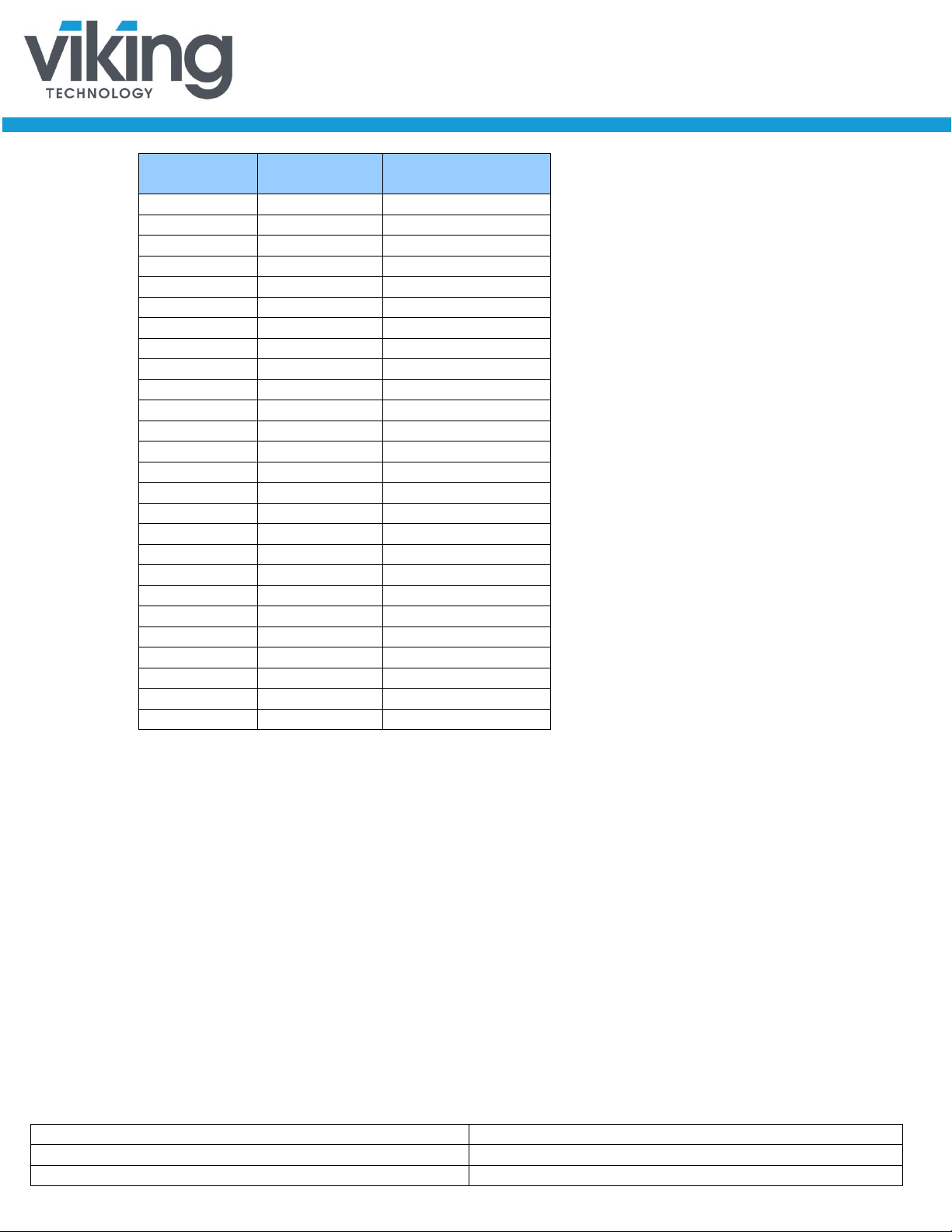
Table 1-1: Element SSD Features
The Element SSD Processor delivers the following features:
Feature
VRFS1xGA
VRFS1xGJ
VRFS1xGF
• • •
VRFS1xGK
VRFS1xGM
Industrial
Versions
interface support for SATA up to
interface support for SATA up to
ensures no data loss resulting from
an unexpected power loss and is
eMLC and MLC NAND flash
• • •
• •
• • •
• •
• •
• • •
• • •
• •
• • •
• • •
VRFS1xGK
only
management and read disturb
www.vikingtechnology.com
• • •
• •
• •
• • •
• • •
• • •
• • •
• • •
• • •
Manual
1/2/2014
PSFS1XXXXGXXXX
Viking Technology
Revision B7
Page 13 of 60
Protection (Factory setting is 3
years)
Thermal sensing energy
management
•
Stainless steel housing for
thermal management
•
RoHS and WEEE compliant
•
Feature
VRFS1xGA
VRFS1xGJ
VRFS1xGF
• • •
VRFS1xGK
VRFS1xGM
Industrial
Versions
ruggedness, low EMI/ESD, and
• • •
• • •
www.vikingtechnology.com
Manual
1/2/2014
PSFS1XXXXGXXXX
Viking Technology
Revision B7
Page 14 of 60
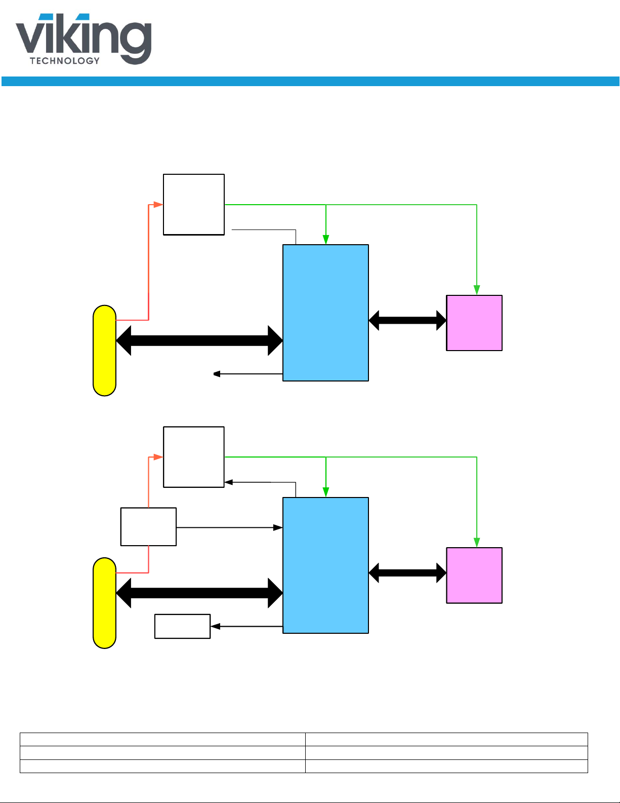
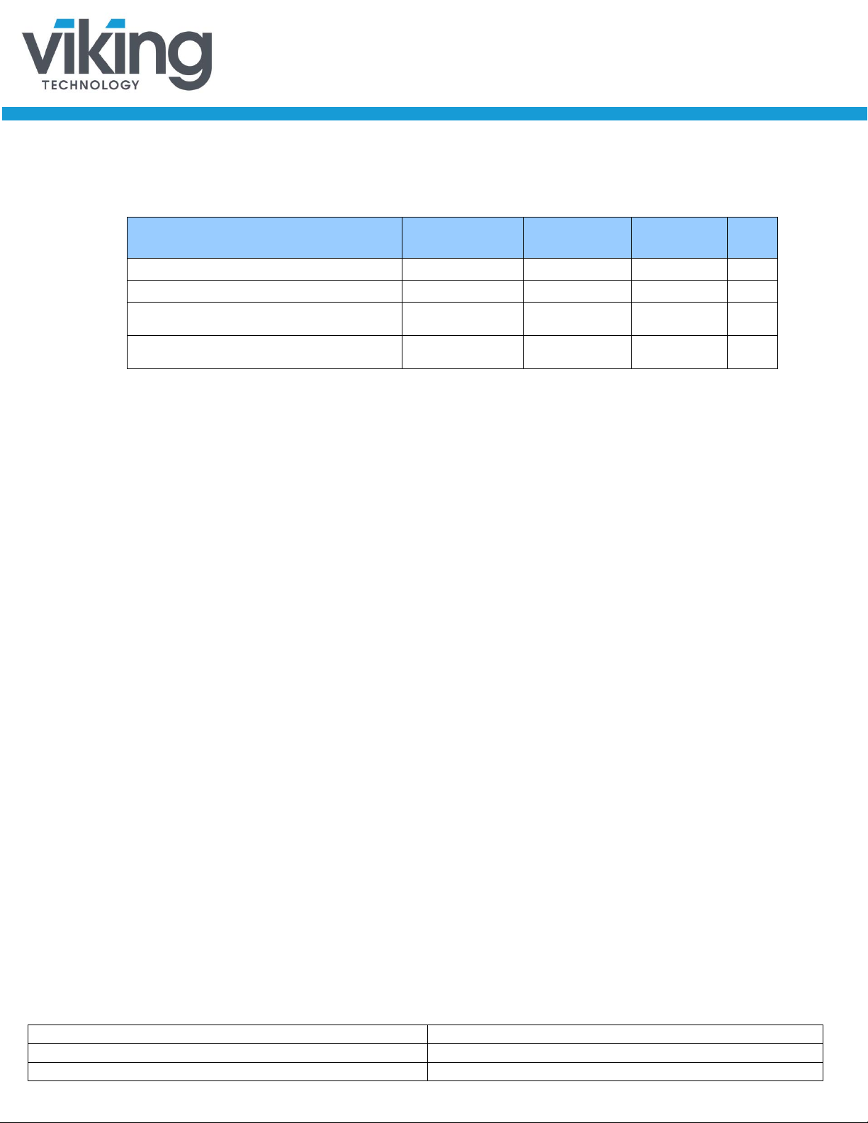
CONTROLLER
Power
Supplies
(2.85V, 1.8V,
1.0V)
uSATA Connector
SATA Interface
FLASH Interface
FLASH
Memory
3.3V
2.85V,
1.0V,
1.8V
2.85V,
1.8V
PAC
Indicator
LEDs
CONTROLLER
Power
Supplies
(2.85V, 1.8V,
1.0V)
VMon
Power_Fail
uSATA Connector
SATA Interface
FLASH Interface
FLASH
Memory
3.3V
2.85V,
1.0V,
1.8V
2.85V,
1.8V
PAC
Indicator
LEDs
Note: PAC in low
1.2 Block Diagram
Figure 1-1: High-Level Block Diagram for Client /Industrial Series
power mode
operates on
2.85V_Standby and
1.0V_Standby
Activity
Signal
Figure 1-2: High-Level Block Diagram for Enterprise Series
www.vikingtechnology.com
Manual
1/2/2014
PSFS1XXXXGXXXX
Viking Technology
Revision B7
Page 15 of 60
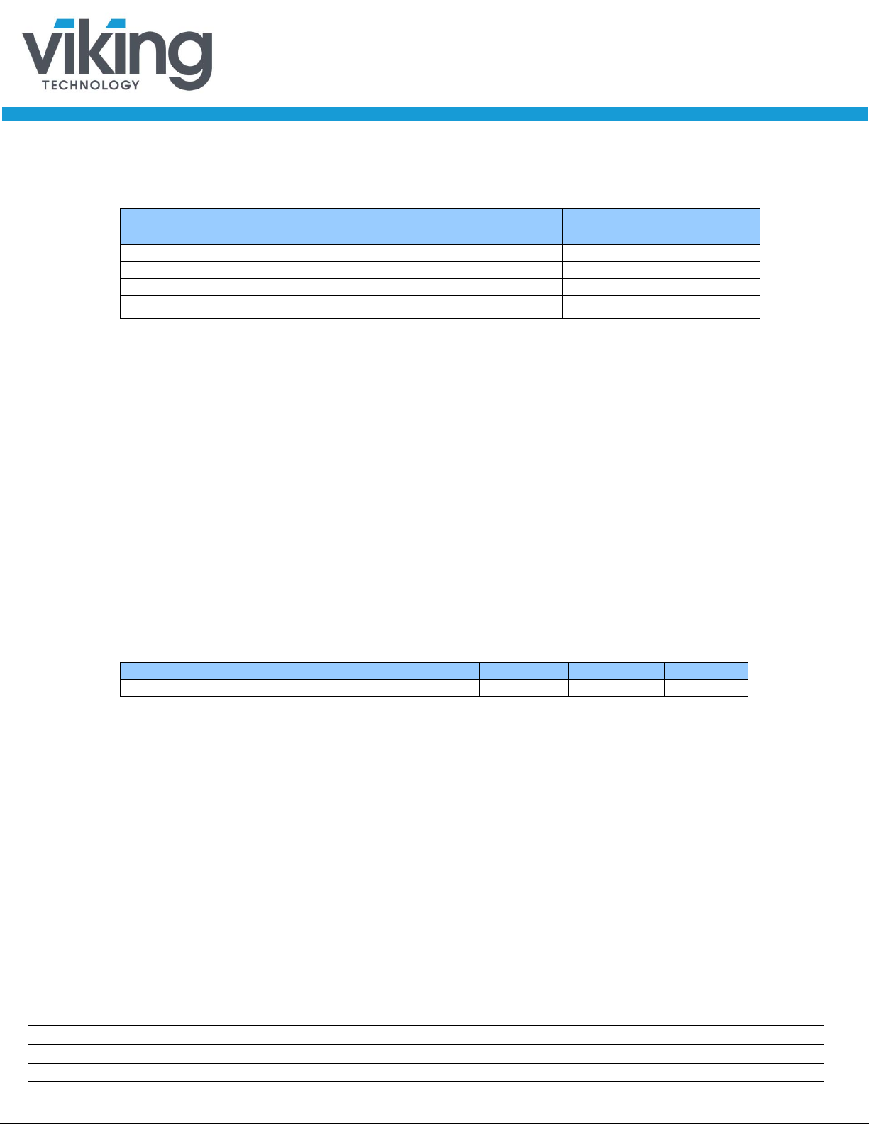
8 6 11,718,750
8
8
16
16
31,277,232
16
12
23,463,216
16
14
27,370,224
16
12.5
24,439,968
24
24
46,905,264
24
22
42,998,256
24
18.75
36,649,368
32
32
62,533,296
32
25
48,858,768
32
30
58,626,288
48
48
93,789,360
48
40
78,161,328
48
45
87,928,848
48
37.5
73,277,568
64
64
125,045,424
64
55
107,463,888
64
60
117,231,408
1.3 SATA Interface for VRFS1xGA, VRFS1xGJ
• The Serial ATA (SATA) interface is compliant with the SATA IO Serial
ATA specification, Revision 2.6 that supports SATA up to 3Gbps.
• The SATA interface connects the host computer to the SSD subsystem.
• The SATA interface runs at a maximum speed of 3 Gbps (Gigabits per
second). If the host computer is unable to negotiate a speed of 3 Gbps,
the SATA interface automatically renegotiates to a speed of 1.5 Gbps.
1.4 SATA Interface for VRFS1xGF, VR FS1 xGK, VRFS1xGM
• The Serial ATA (SATA) interface is com pliant with the SATA IO Serial
ATA specification, revision 3.x that support SATA up to 6 Gbps.
• The SATA interface connects the host computer to the SSD subsystem.
• The SATA interface runs at a maximum speed of 6.Gbps (Gigabits per
second). If the host computer is unable to negotiate a speed of 6 Gbps,
the SATA interface automatically renegotiates to a speed of 3 or 1.5 Gbps.
For a list of supported commands and other specifics, please see Chapter 5.
2 Product Specifications
2.1 Capacity-LBA
Table 2-1: Capacity and LBA Count
CAPACITY
RAW
CAPACITY
USER
512_LBA_COUNT
15,625,000
www.vikingtechnology.com
Manual
1/2/2014
PSFS1XXXXGXXXX
Viking Technology
Revision B7
Page 16 of 60
RAW
USER
64
50
97,696,368
96
80
156,301,488
96
90
175,836,528
96
96
187,557,552
96
75
146,533,968
128
120
234,441,648
128
128
250,069,680
128
121
236,395,152
128
100
195,371,568
192
160
312,581,808
192
180
351,651,888
192
192
375,093,936
192
150
293,046,768
256
240
468,862,128
256
256
500,118,192
256
251
490,350,672
256
225
439,559,568
256
200
390,721,968
384
360
703,282,608
384
384
750,166,704
384
335
654,445,008
384
300
586,072,368
512
480
937,703,088
512
512
1,000,215,216
512
450
878,977,968
512
400
781,422,768
CAPACITY
CAPACITY
512_LBA_COUNT
2.2 Performance
Maximum SSD performance can be achieved for certain workloads by:
• Initiating read and write transfers for random accesses with small block
sizes of 4k bytes to optimize IOP’s performance for applications such as
databases, OLTP etc.
• Initiating read and write transfers for sequential accesses with large blocks
(128k or larger) to optimize performance toward throughput (MBps) for
applications such as video streaming, data acquisition etc.
• Issuing transfers at starting LBA’s that align the access on 4k boundaries:
o Minimizes or eliminates internal Read-Modify-Write operations
o Align on 4k boundaries is optimal for SSD capacities up to 256 GB
o For SSD capacities greater than 256 GB, aligning on 8k boundaries
is optimal
www.vikingtechnology.com
Manual
1/2/2014
PSFS1XXXXGXXXX
Viking Technology
Revision B7
Page 17 of 60
Sequential Read, 128K block size
Sequential Write, 128K block size
Random Read, 4K block size
Up to
60,000
Random Write, 4K block size
60,000
• Avoid mixing NCQ and non-NCQ commands
Table 2-2: Maximum Sustained Read and Write: MB/sec and IOPS
Access Type
Notes:
1. Performance measured after SSD preconditi oning
2. Tested with IOmeter 08 and queue depth (QD) set to 32.
3. Write Cache enabled.
4. Random IO P S (Input/Output Operations per Second) cover the entire range of legal logical block
addresses (LBA’s). Measurements ar e performed on a full drive (all LBA’s have valid content).
5. Performance may vary by NAND type and host.
6. Refer to Application Note AN0006 for Viking S SD Benchmarking Methodology.
VRFS1xGA
VRFS1xGJ
Up to 260 Up to 500 Up to 520 MB/s
Up to 260 Up to 500 Up to 520 MB/s
Up to 30,000 Up to 60,000
Up to 30,000 Up to 20,000
VRFS1xGK
VRFS1xGM
VRFS1xGF
VRFS1xGN
Up to
Units
IOPS
IOPS
www.vikingtechnology.com
Manual
1/2/2014
PSFS1XXXXGXXXX
Viking Technology
Revision B7
Page 18 of 60
Type
Average Latency (ms)
Power On to Ready (POR)
<1
Reset to Ready
<2
Command to DRQ
<1
Time to Erase (ATA Secure Erase)
4 second (entire drive)
Power Cycle Endurance
Min
Max
Unit
STANDBY IMMEDIATE to WE completed
-
40
ms
2.3 Timing
Table 2-3: Timing Specifications
Write Cache Enabled
Notes:
1. Based on MLC NAND
2. Device measu red using IOMETER 08, Queue depth s et to 32 for NCQ
3. Sector Rea d/Write latency measured up ton 4K block size (512B/sector = 1 Block), random access
4. Sequential IOPS cover the entire range of vali d logical block addresses (LBA’s). Measurements are
performed on a full drive (all LBA’s have valid content)
2.3.1 STANDBY IMMEDIATE Command
The Power On to Ready time assumes a proper shutdown (power removal
preceded by STANDBY IMMEDIATE command. A STANDBY IMMEDIATE
before power down always performs a graceful shutdown and does not require
the use of the hold-up circuit. Note that SMART attribute 174 "Unexpected Power
Loss" records the number of non-graceful power cycle events.
The timings for when a STANDBY IMMEDIATE is issued to when it is completed
are shown in the table below.
Table 2-4: STANDBY IMMEDIATE Timing
www.vikingtechnology.com
 Loading...