

Page 1
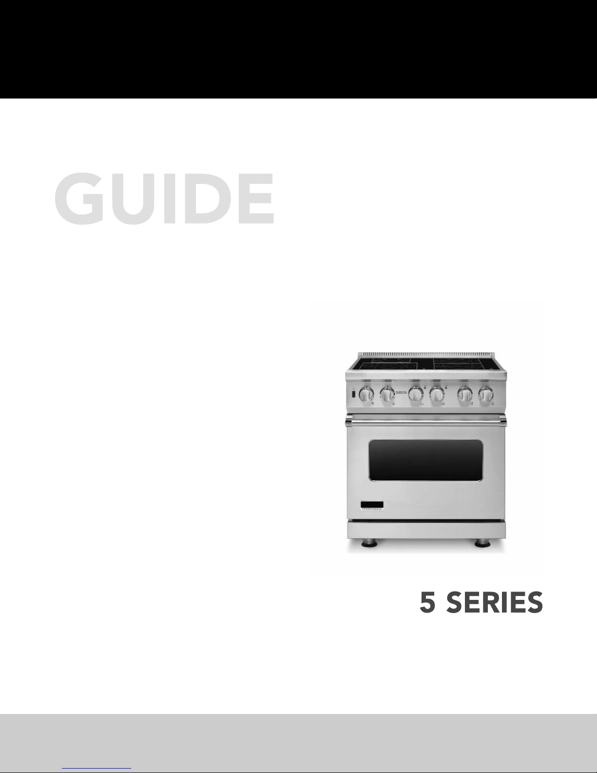
Install
Freestanding Electric and
Induction 30”W. Ranges
VESC / CVESC530
VISC530 / CVISC530
Page 2

2
Table of Contents
Warnings & Important Safety Instructions _______________________________________________3
VESC Dimensions____________________________________________________________________6
VESC Specifications__________________________________________________________________7
VISC Dimensions ____________________________________________________________________8
VISC Specifications __________________________________________________________________9
Clearance Dimensions (Proximity to Cabinets)__________________________________________10
Clearance Dimensions (Wood/Composite Overlay) _____________________________________11
Electrical Requirements _____________________________________________________________12
General Information ________________________________________________________________13
Installation_________________________________________________________________________14
Door Removal ______________________________________________________________14
Leg Installation______________________________________________________________15
Electrical Connection (3-wire) _________________________________________________16
Electrical Connection (4-wire) _________________________________________________18
Leveling/Adjustments/Alignment ______________________________________________20
Anti-tip Device Installation Wall Mount_________________________________________22
Anti-tip Device Installation Floor Mount ________________________________________23
Final Installation_____________________________________________________________24
Door Replacement and Adjustment ___________________________________________25
Final Preparation ___________________________________________________________________26
Performance Checklist ______________________________________________________________26
Service & Registration_______________________________________________________________27
Page 3
IMPORTANT
3
• Before beginning, please read these
instructions completely and carefully.
• DO NOT remove permanently affixed
labels, warnings, or plates from product.
This may void the warranty.
• All local and national codes and ordinances
must be observed. Installation must
conform with local codes or in the absence
of codes, the National Fuel Gas Code
ANSIZ233.1/NFPA-54 –latest edition.
• The installer must leave these instructions
with the consumer who should retain for
local inspector’s use and for future reference.
In Canada: Installation must be in accordance
with the current CSA C22.1 Canadian
Electrical Codes Part 1 and/or local codes.
Your safety and the safety of others is
very important.
We have provided many important safety
messages in this manual and on your
appliance. Always read and obey all
safety messages.
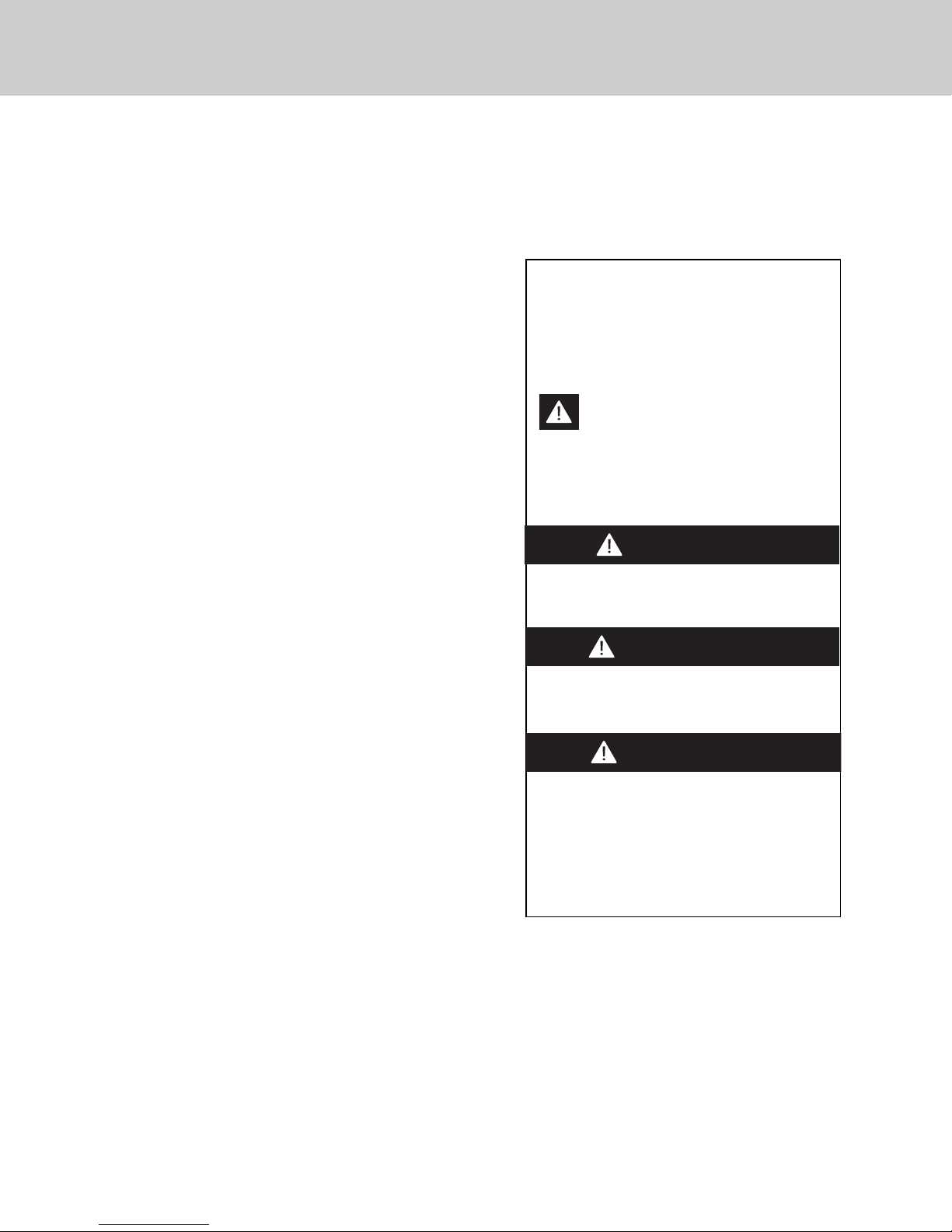
This is the safety alert symbol. This
symbol alerts you to hazards that
can kill or hurt you and others.
All safety messages will be preceded by
the safety alert symbol and the word
“DANGER,” “WARNING” or “CAUTION.”
These words mean:
Hazards or unsafe practices
which WILL result in severe personal
injury or death
DANGER
Hazards or unsafe practices
which COULD result in severe personal
injury or death
Hazards or unsafe practices which
COULD result in minor personal injury or
property damage.
All safety messages will identify the
hazard, tell you how to reduce the chance
of injury, and tell you what can happen if
the instructions are not followed.
WARNING
CAUTION
–Read and Follow!
Page 4
IMPORTANT–Please Read and Follow!
4
WARNING
To prevent possible damage to cabinets
and cabinet finishes, use only materials
and finishes that will not discolor or
delaminate and will withstand temperatures
up to 194°F (90°C). Heat resistant
adhesive must be used if the product is to
be installed in laminated cabinetry. Check
with your builder or cabinet supplier to
make sure that the materials meet these
requirements.
A GFI
shall be used if required by NFPA-70 (National Electric Code), federal/state/local laws, or
local ordinances.
• The required use of a GFI is normally related to the location of a receptacle with respect to
any significant sources of water or moisture.
• Viking Range Corporation will NOT warranty any problems resulting from GFI outlets which
are not installed properly or do not meet the requirements below.
If the use of a GFI is required
, it should be:
• Of the receptacle type (breaker type or portable type NOT recommended)
• Used with permanent wiring only (temporary or portable wiring NOT recommended)
• On a dedicated circuit (no other receptacles, switches or loads in the circuit)
• Connected to a standard breaker of appropriate size (GFI breaker of the same size NOT
recommended)
• Rated for Class A (5 mA +/- 1 mA trip current) as per UL 943 standard
• In good condition and free from any loose-fitting gaskets (if applicable in outdoor situations)
• Protected from moisture (water, steam, high humidity) as much as reasonably possible
Page 5
5
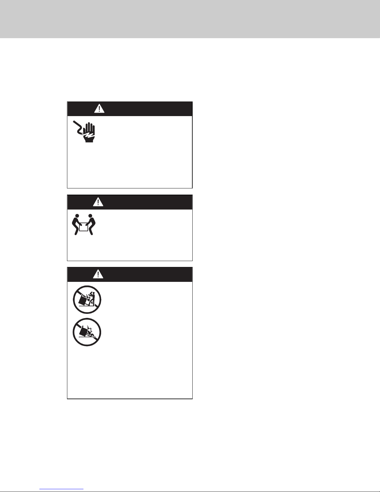
DANGER
ELECTRICAL SHOCK
HAZARD
To avoid risk of electrical shock,
personal injury or death; verify
your appliance has been properly
grounded in accordance with local codes
or in absence of codes, with the National
Electrical Code (NEC). ANSI/NFPA 70latest edition.
WARNING
MOVING HAZARD
To avoid risk of severe
personal injury; this appliance
requires two or more personnel while
handling and moving. Possible use of
appliance moving devices is recommended.
WARNING
TIPPING HAZARD
To reduce the risk of the
appliance tipping, it must be
secured by a properly installed
anti-tip bracket(s). To make sure
the bracket has been installed
properly, look behind the range
with a flashlight to verify proper
installation engaged in the rear
top left corner of the range.
• THIS RANGE CAN TIP.
• INJURIES TO PERSONS CAN RESULT.
• INSTALL ANTI-TIP DEVICE PACKED
WITH RANGE.
• SEE INSTALLATION INSTRUCTIONS.
Page 6
6
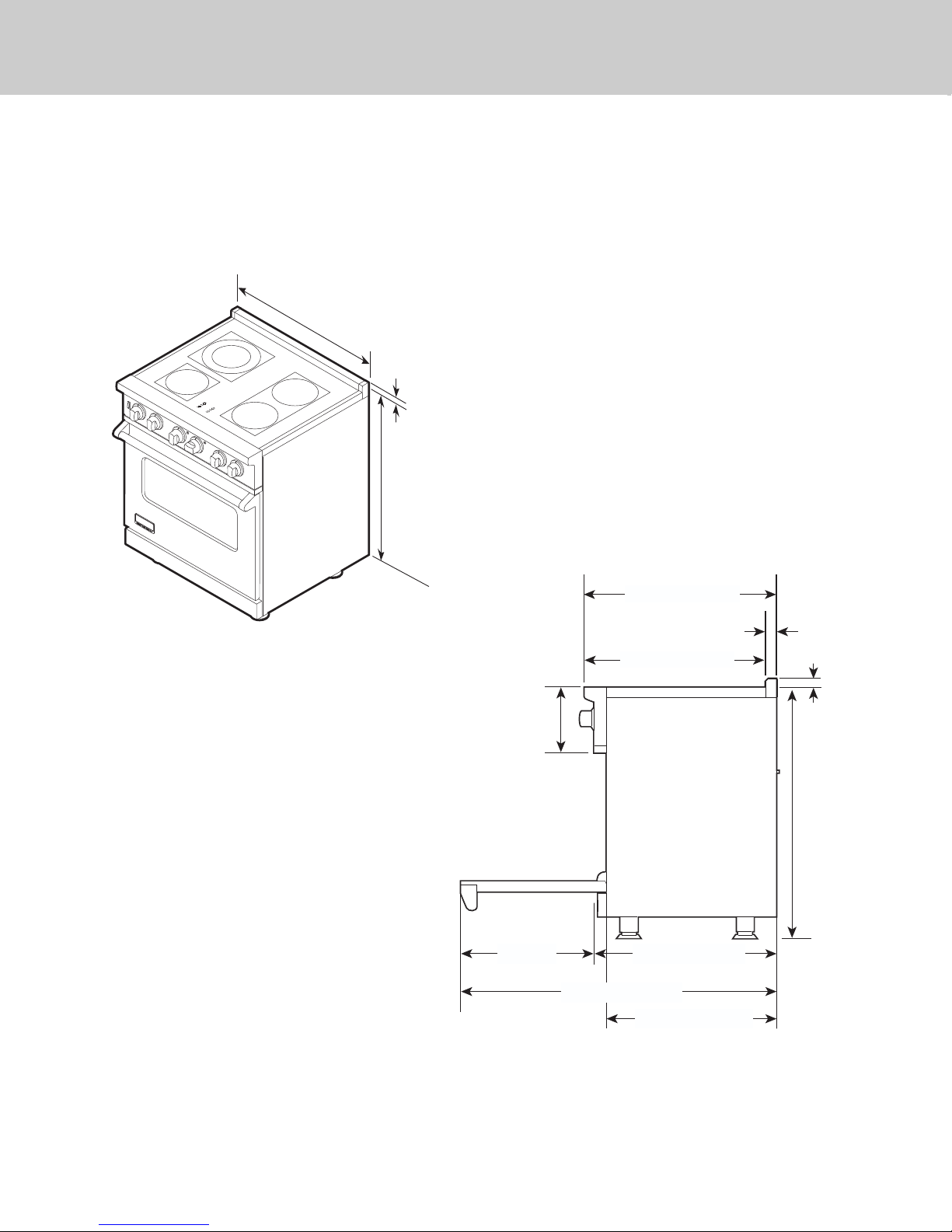
Dimensions VESC
*Note: Unit shown with standard island trim.
Electric 30” Range
29-7/8”
(75.9 cm)
1”
(2.5 cm
)*
35-7/8”
(91.1 cm) min.
to
(94.0 cm) max.
37”
28-1/16” (71.2 cm)
1-5/8”
(4.1 cm)
26-7/16” (67.2 cm)
1” (2.5 cm)
8-1/8”
(20.6 cm)
19-3/8”
(49.2 cm)
45-1/8” (114.6 cm)
35-7/8”
(91.1 cm) min.
to
37”
(94.0 cm) max.
25-3/4” (65.4 cm)
24-5/16” (61.8 cm)
Page 7
7
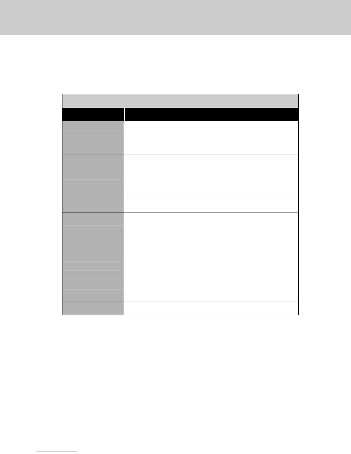
Specifications VESC
Electric 30” Range
Description
VESC530 / CVESC530
Overall width
29-7/8” (75.9 cm)
Overall height To top of glass frame
35-7/8” (91.1 cm) min.
37” (94.0 cm) max.
Legs adjust 1-1/8” (2.9 cm)
Overall depth from
rear
To end of side panel—24-5/16” (61.8 cm)
To front of door—25-3/4” (65.4 cm)
To end of landing ledge—28-1/16” (71.3 cm)
To end of door handle—28-11/16” (72.9 cm)
Additions to base
height
To top of island trim—add 1” (2.5 cm)
To top of backguard—add 8” (20.3 cm)
To top of high-shelf—add 23-1/2” (59.7 cm)
Electrical
requirements
See Electrical Requirements information.
Maximum amp usage 240V—59.0 amps
208V—51.3 amps
Surface element rating
Left front
Left rear
Right front
Bridge
Right rear
1,500 watts
2,500 watts/1,000 watts
1,800 watts
800 watts
1,800 watts
Oven interior width
25-5/16” (64.6 cm)
Oven interior height
16-1/2” (41.9 cm)
Oven interior depth
AHAM 16-13/16” (42.7 cm) Overall—19-1/2” (49.5 cm)
Oven volume Total oven capacity—4.7 cu. ft.
Measure to AHAM standards 4.1 cu. ft.
Approximate
shipping weight
426 lbs. (193.2 kg)
Minimum clearances from adjacent combustible construction
• Cooking surface and below, i.e., 36” (91.4 cm) and below
o Sides—0”
• Above cooking surface, i.e. above 36" (91.4 cm)
o Sides—6” (15.2 cm)
o Within 6” (15.2 cm) side clearance, wall cabinets no deeper than 13” (33.0 cm) must be minimum 18” (45.7 cm)
above cooking surface.
o Wall cabinets directly above product must be minimum 36” (91.4 cm) for open top burners above cooking surface.
o Rear—0” with backguard or highshelf; 0” with island trim and noncombustible rear wall; 6” (15.2 cm) with island
trim and combustible rear wall.
Page 8
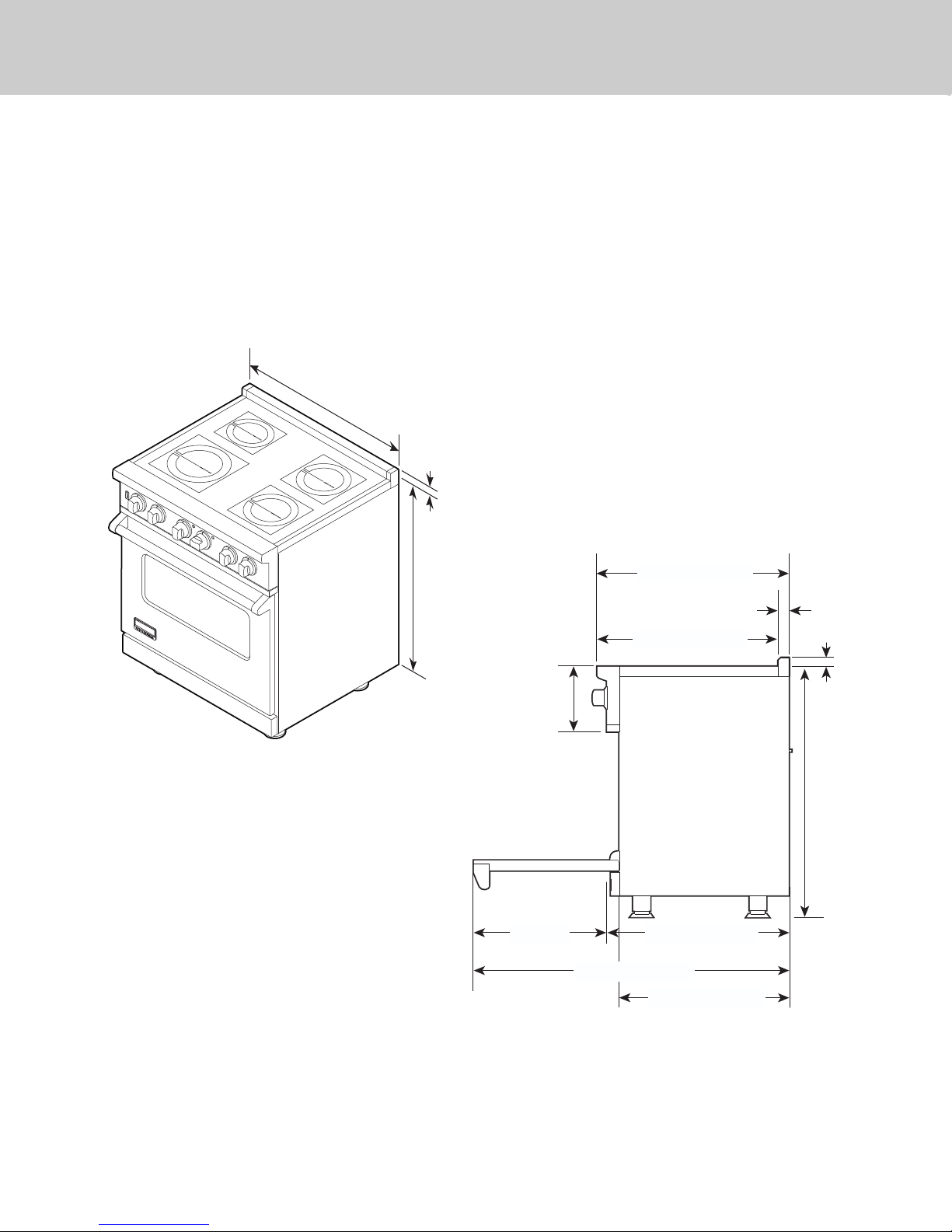
Dimensions VISC
8
Induction 30” Range
*Note: Unit shown with standard island trim.
29-7/8”
(75.9 cm)
H
O
R
T
E
A
R
F
R
H
O
N
O
T
R
T
E
A
R
F
R
O
N
T
1”
(2.5 cm)
35-7/8”
(91.1 cm) min.
to
(94.0 cm) max.
37”
28-1/16” (71.2 cm)
1-5/8”
(4.1 cm)
26-7/16” (67.2 cm)
1” (2.5 cm)
8-1/8”
(20.6 cm)
19-3/8”
(49.2 cm)
45-1/8” (114.6 cm)
35-7/8”
(91.1 cm) min.
to
37”
(94.0 cm) max.
25-3/4” (65.4 cm)
24-5/16” (61.8 cm)
Page 9
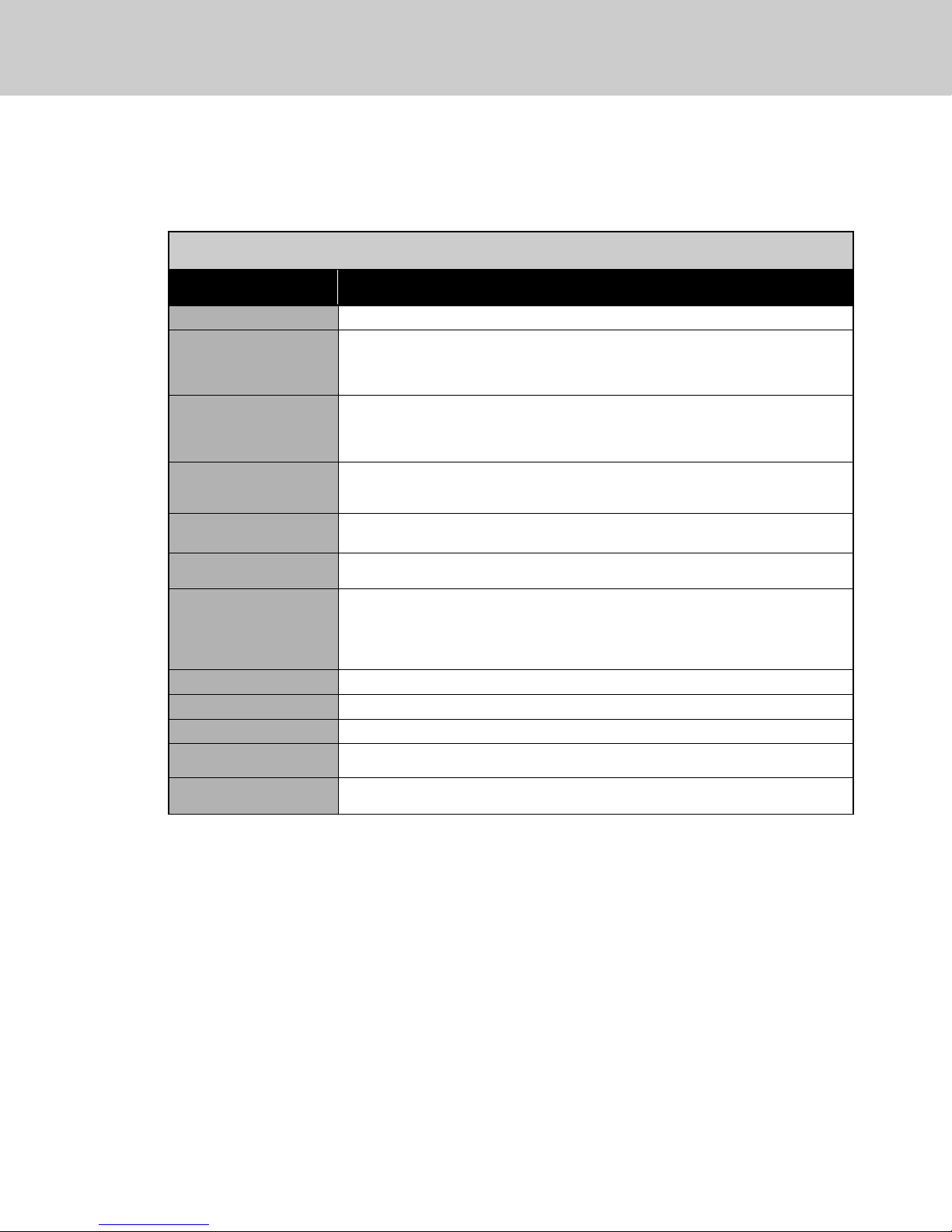
Specifications VISC
9
Electric Induction 30”W. Range
Description
VISC530 / CVISC530
Overall width
29-7/8” (75.9 cm)
Overall height To top of glass frame
35-7/8” (91.1 cm) min.
37” (94.0 cm) max.
Legs adjust 1-1/8” (2.9 cm)
Overall depth from
rear
To end of side panel—24-5/16” (61.8 cm)
To front of door—25-3/4” (65.4 cm)
To end of landing ledge—28-1/16” (71.3 cm)
To end of door handle—28-11/16” (72.9 cm)
Additions to base
height
To top of island trim—add 1” (2.5 cm)
To top of backguard—add 8” (20.3 cm)
To top of high-shelf—add 23-1/2” (59.7 cm)
Electrical
requirements
See “Electrical Requirements” section.
Maximum amp usage 240V—54.9 amps
208V—51.7 amps
Surface element rating
Left front
Left rear
Right front
Right rear
3,700 watts boost/2,300 watts
1,400 watts
1,850 watts
1,850 watts
Oven interior width
25-5/16” (64.6 cm)
Oven interior height
16-1/2” (41.9 cm)
Oven interior depth
AHAM 16-13/16” (42.7 cm) Overall—19-1/2” (49.5 cm)
Oven volume Total oven capacity—4.7 cu. ft.
Measure to AHAM standards 4.1 cu. ft.
Approximate
shipping weight
426 lbs. (193.2 kg)
Minimum clearances from adjacent combustible construction:
• Cooking surface and below, i.e., 36” (91.4 cm) and below
o Sides—0”
• Above cooking surface, i.e. above 36" (91.4 cm)
o Sides—6” (15.2 cm)
o Within 6” (15.2 cm) side clearance, wall cabinets no deeper than 13” (33.0 cm) must be minimum 18” (45.7 cm)
above cooking surface.
o Wall cabinets directly above product must be minimum 36” (91.4 cm) for open top burners above cooking surface.
o Rear—0” with backguard or highshelf; 0” with island trim and noncombustible rear wall; 6” (15.2 cm) with island
trim and combustible rear wall.
Page 10
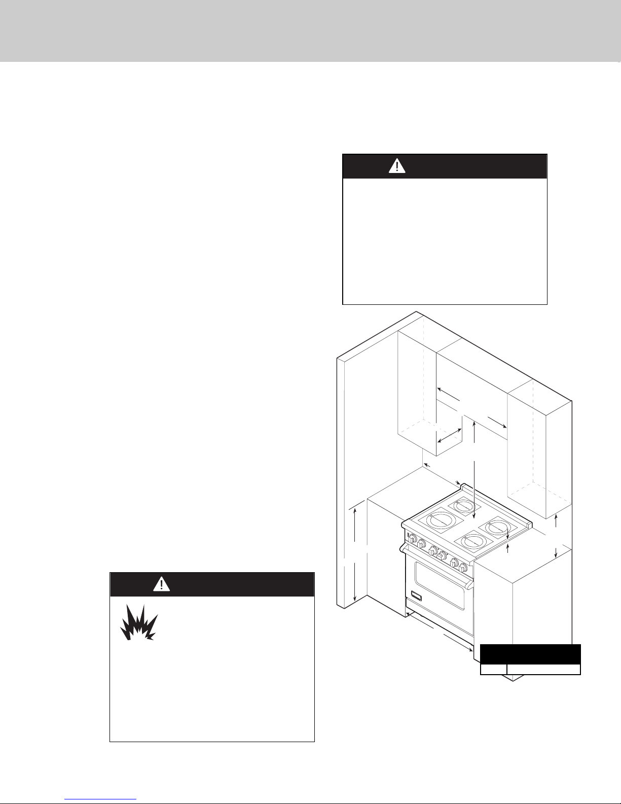
Clearance Dimensions (Proximity to Cabinets)
10
CAUTION
Burn hazard.
To avoid risk of personal injury;
the use of cabinets for storage
above the appliance may result
in a potential burn hazard. Combustible
items may ignite, metallic items may
become hot and cause burns. If a cabinet
storage is to be provided the risk can be
reduced by installing a rangehood that
projects horizontally a minimum 5”
(12.7 cm) beyond the bottom of cabinets.
CAUTION
To prevent possible damage to cabinets
and cabinet finishes, use only materials
and finishes that will not discolor or
delaminate and will withstand temperatures
up to 194°F (90°C). Heat and moisture
resistant adhesive must be used if the
product is to be installed in laminated
cabinetry. Check with your builder or
cabinet supplier to make sure that the
materials meet these requirements.
• This range may be installed directly
adjacent to existing 36” (91.4 cm) high
base cabinets.
IMPORTANT: The side trim MUST be
3/8” (.95 cm) above the adjacent base
cabinet countertop. This can be
accomplished by raising the unit using the
adjustment spindles on the legs.
• The range CANNOT be installed directly
adjacent to sidewalls, tall cabinets, tall
appliances, or other side vertical surfaces
above 36” (91.4 cm) high. There must be a
minimum of 6” (15.2 cm) sideclearance
from the range to such combustible
surfaces above the 36” (91.4 cm) counter
height.
• Within the 6” (15.2 cm) side clearance to
combustible vertical surfaces above 36”
(91.4 cm), the maximum wall cabinet
depth must be 13” (33.0 cm) and wall
cabinets within this 6” (15.2 cm) side
clearance must be 18” (45.7 cm) above the
36” (91.4 cm) high countertop.
• Wall cabinets above the range must be a
minimum of 42” (106.7 cm) above the
range cooking surface for the full width of
the range. This minimum height
requirement does not apply if a range
hood is installed over the cooking surface.
Note: Minimum clearance for back wall is 0” with
backguard or high-shelf.
Note: If a range hood is installed, wall cabinets
above the range have a different minimum
clearance height.
Range
Width
“A”
Dimension
30” 30” (76.2 cm)
29-7/8”
(75.9 cm)
13” max.
33.0 cm)
36”
91.4 cm)
(
(
6” min.
(15.2 cm)
HO
R
T
E
A
R
F
R
HO
O
N
T
R
T
E
A
R
FR
O
N
T
(opening width)
A
42” min.
(106.7 cm)
3/8”
(0.95 cm)
18” min.
(45.7 cm
)
Page 11
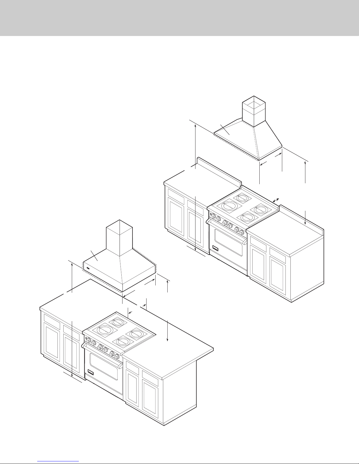
Clearance Dimensions (Wood/Composite Overlay)
11
The bottom of a standard hood should be
30” (76.2 cm) min. to 36” (91.4 cm) max.
above the countertop. This would typically
result in the bottom of the hood being
66” (167.6 cm) to 72” (182.9 cm) above the
floor. Refer to the range hood installation
instructions for additional information. These
dimensions provide for safe and efficient
operation of the hood.
H
O
T
R
E
A
R
F
R
O
N
T
H
O
T
R
E
A
R
F
R
O
N
T
H
O
T
R
E
A
R
F
R
O
N
T
H
O
T
R
E
A
R
F
R
O
N
T
66”min.
(167.6 cm)
to
72”max.
(182.9 cm)
66”min.
(167.6 cm)
to
72”max.
(182.9 cm)
24”
(61.0 cm)
or
27”
(38.6 cm)
30”
(76.2 cm)
6”
(15.2 cm)
Wood/Composite
Overlay
Wood/Composite
Overlay
30”min.
(76.2 cm)
to
36”max.
(91.4 cm)
0”
(
0 cm)
30”min.
(76.2 cm)
to
36”max.
(91.4 cm)
Wall Installation
Island Installation
Note: Minimum clearance for back wall is
0” with backguard or high-shelf.
Important: This range comes standard
with an Island Trim. There must be a
minimum of 6” (15.2 cm) clearance from
rear of range to a combustible wall.
Clearances from non-combustible
materials are not part of the ANSI Z21.1
scope and are not certified by CSA.
Clearances to non-combustible materials
must be approved by the authority having
jurisdiction.
Page 12
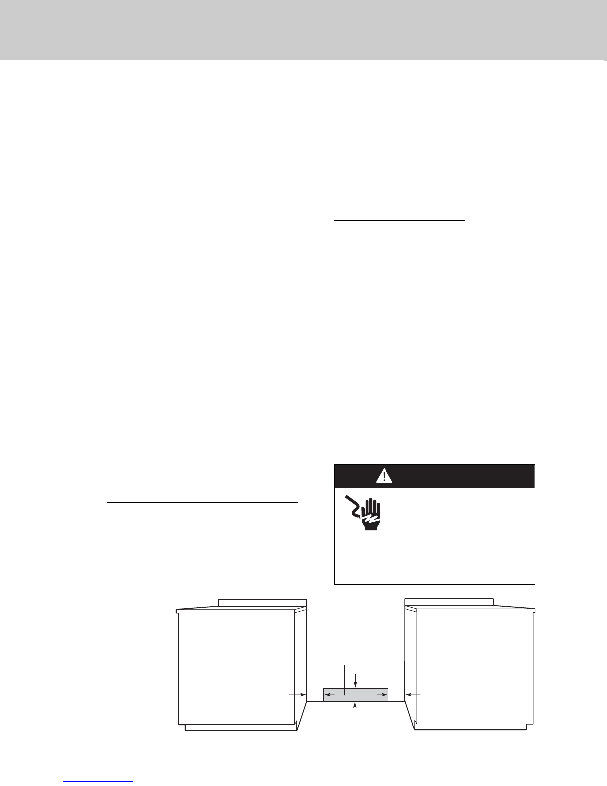
Electrical Requirements
12
Electrical
connection
in this area
4-3/8”
(11.1 cm)
6”
(15.2 cm)
6”
(15.2 cm)
WARNING
Electrical shock hazard.
To avoid the risk of electrical
shock, personal injury or death;
verify electrical power is turned
off at the breaker box until the range is
installed and ready to operate, installation
by an authorized installer only.
Induction
30” Range
Electrical Requirements
This product is manufactured with the
neutral terminal connected to the cabinet.
Use a 3-wire, agency approved, power
supply kit with closed loop terminals rated
per the National Electrical Code, ANSI/NFPA
70-latest edition (See Rating chart below). If
local codes prohibit grounding through the
neutral, use a 4-wire, agency approved,
power supply kit with closed loop terminals
rated per the National Electrical Code,
ANSI/NFPA 70-latest edition (See Rating
chart below).
RATING* Specified Rating of Power
Supply Cord Kit and Circuit Protection
120/240 Volts 120/208 Volts Amps
12.5 - 16.5 KW 9.2 - 12.5 KW 40 or 50
16.5 - 17.5 KW 12.5 - 13.5 KW 50
*The National Electric Code calculation for
Electrical Load is less than the Total
Connected Electrical Load listed on the
model/serial rating plate.
A GFI
shall be used if required by NFPA-70
(National Electric Code), federal/state/local
laws, or local ordinances.
• The required use of a GFI is normally
related to the location of a receptacle with
respect to any significant sources of water
or moisture.
• Viking Range, LLC will NOT warranty any
problems resulting from GFI outlets which
are not installed properly or do not meet
the following requirements.
If the use of a GFI is required
, it should be:
• Of the receptacle type (breaker type or
portable type NOT recommended)
• Used with permanent wiring only
(temporary or portable wiring NOT
recommended)
• On a dedicated circuit (no other
receptacles, switches or loads in the
circuit)
• Connected to a standard breaker of
appropriate size (GFI breaker of the same
size NOT recommended)
• Rated for Class A (5 mA +/- 1 mA trip
current) as per UL 943 standard
• In good condition and free from any
loose-fitting gaskets (if applicable in
outdoor situations)
• Protected from moisture (water, steam,
high humidity) as much as reasonably
possible
Page 13
13
General Information
READ AND FOLLOW ALL WARNING
AND CAUTION INFORMATION WHEN
INSTALLING THIS APPLIANCE.
• All openings in the wall behind the
appliance and in the floor under the
appliance must be sealed.
• DO NOT obstruct the flow of combustion
and ventilation air.
Moving, Handling, and Unpacking
Remove and discard all packing materials,
including cardboard and tape on the outside
and inside of the range.
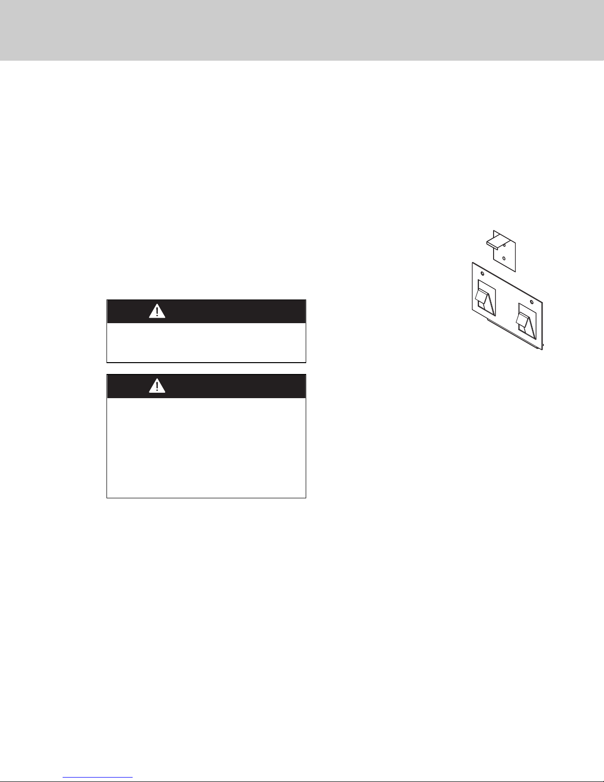
Range – Do not discard the
anti-tip metal brackets
supplied with the range. These
are the anti-tip device and
must be installed with the unit.
Refer to “Anti-tip Device
Installation”
section.
Some stainless steel parts may
have a plastic protective wrap which must be
peeled off. The interior should be washed
thoroughly
with hot, soapy water to remove film
residues and any dust or debris before being
used, then rinsed and wiped dry. Solutions
stronger than soap and water are rarely
needed.
CAUTION
Avoid any damage to oven vents. The vents
need to be unobstructed and open to provide
proper airflow for optimal oven performance.
CAUTION
The cooling fan should be operating when
the unit is in operation. If you notice the
cooling fan is not operating or you observe
unusual or excessive noise coming from the
cooling fan, contact an authorized service
center before continuing operation. Failure to
do so can result in damage to the oven or
surrounding cabinets.
Page 14
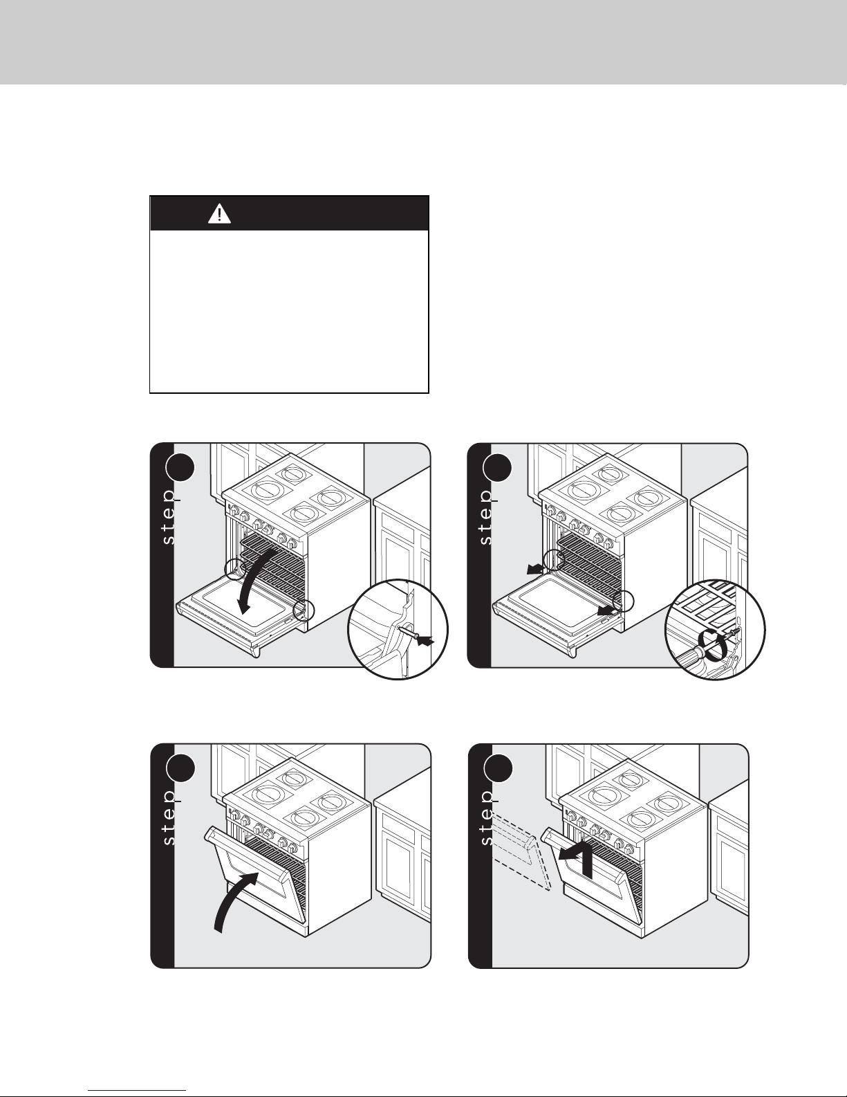
14
CAUTION
To avoid risk of personal injury or product
damages, DO NOT use the handle or
oven door to lift the oven. Remove door
before installation to ensure that it is not
used to lift the unit. DO NOT lift or carry
the door by the handle.
Removing the door must be done by your
dealer, or a qualified licensed plumber.
Door Removal
1
H
O
T
R
E
A
R
F
R
O
N
T
H
O
T
R
E
A
R
F
R
O
N
T
Open door completely. Place pins,
supplied with unit, in pin hole. For personal safety,
ONLY use pins supplied with the unit.
2
H
O
T
R
E
A
R
F
R
O
N
T
H
O
T
R
E
A
R
F
R
O
N
T
Remove hinge trim screws. Take off hinge trim. Identify
right and left hinge for future re-installation.
3
H
O
T
R
E
A
R
F
RO
N
T
H
O
T
RE
A
R
F
R
O
NT
Close until pins stop door.
4
H
O
T
R
E
A
R
F
R
O
N
T
H
O
T
R
E
A
R
F
R
O
N
T
Lift door up and out.
Installation
Page 15
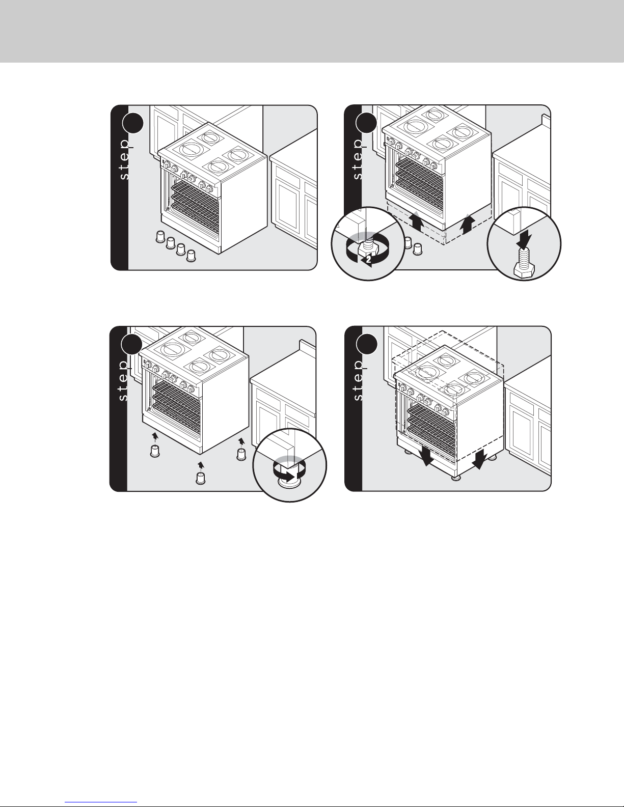
15
1
1
Legs are packed in styrofoam top pack.
Note: Legs should be installed near to where
appliance is to be used, as they are
not secure for long transit.
Note: It is strongly recommended
that a pallet or lift jack be used rather than tilting.
Raise unit about a foot.
Unscrew temporary legs from
couplings
.
Lower range gently to keep any undue strain from
legs and internal mounting hardware.
Screw legs into couplings on all
four corners.
Leg Installation
1
H
O
RE
T
A
R
F
RO
H
N
O
T
R
T
E
A
R
F
R
O
N
T
3
H
O
RE
T
A
R
F
RO
H
N
O
T
RE
T
A
R
F
R
O
N
T
2
H
O
R
T
E
A
R
F
RO
H
N
O
T
REA
T
R
F
R
O
NT
3
2
2
4
H
O
RE
T
A
R
F
R
H
O
N
O
T
RE
T
A
R
F
R
O
NT
Page 16
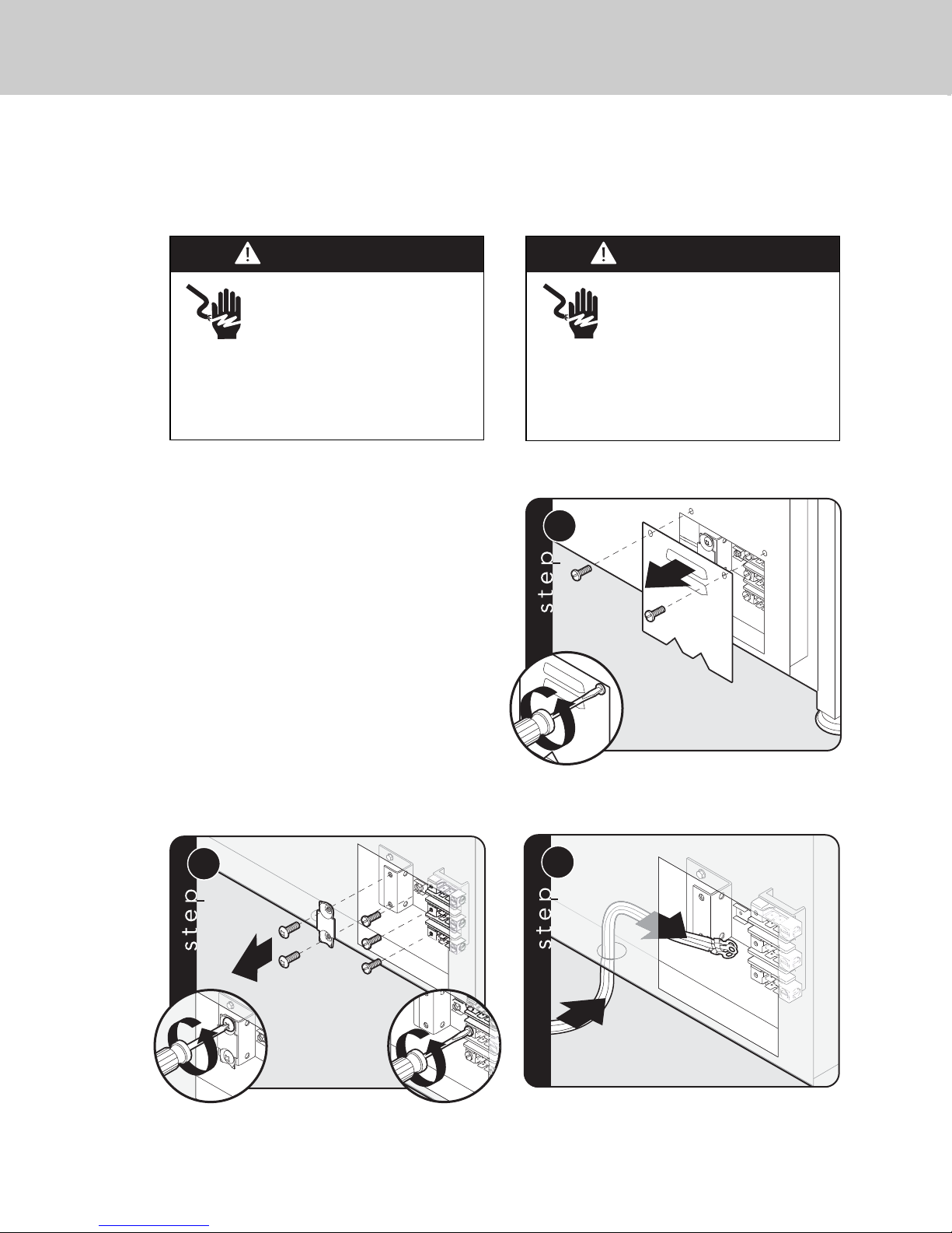
16
2
1
1
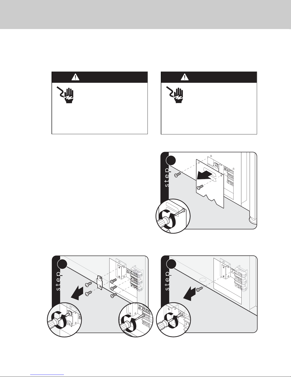
Remove access door.
Electrical Connection (3-wire)
3
2
1
2
Remove supply cord strain relief
bracket and three supply cord mounting screws
on terminal block.
WARNING
Electrical shock hazard.
To avoid risk or electrical
shock, personal injury or death;
grounding product to the frame
of the unit may or may not be permitted
through your local codes. If ground to the
frame is not permitted then a 4 conductor
power cord must be used.
WARNING
Electrical shock hazard.
To avoid risk of electrical shock,
personal injury or death; verify
your appliance has been
properly grounded in accordance with
local codes or in absence of codes, with
the National Electrical Code (NEC).
ANSI/NFPA 70-latest edition.
3
Feed supply cord up through hole in bottom
of range back.
Note: If you have a 4-wire connection, see following section for
4-wire connection instructions.
See “Electrical Requirements” information.
Where local codes do not permit grounding
through neutral, use a 4-wire power supply
cord. The cord or conduit must be secured
to the range with the strain relief bracket.
The electrical connection is made at the
terminal block, which is located behind the
access door on the back of the range.
Page 17
17
1
2
4
1
1
3
5
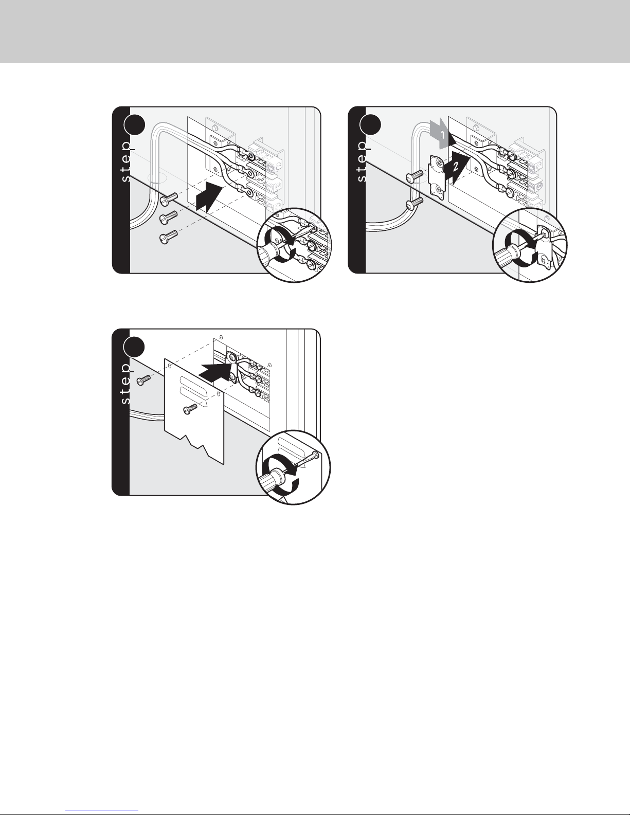
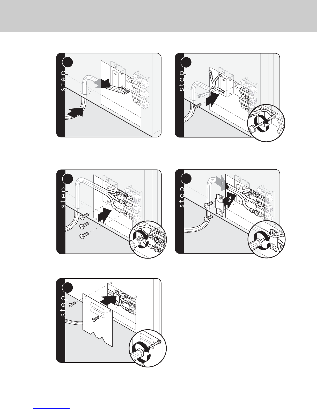
Attach line #1 (red) and line #2 (black)
leads to outside terminal. Attach neutral wire (white)
to center terminal on the terminal block.
Push supply cord toward terminal
block to relieve strain, reattach supply cord strain
relief bracket over supply cord.
1
2
6
Reattach access door.
Page 18
18
2
1
1
3
2
1
2
Remove access door.
Remove supply cord strain relief
bracket and three supply cord mounting screws
on the terminal block.
Electrical Connection (4-wire)
WARNING
Electrical shock hazard.
To avoid risk or electrical
shock, personal injury or death;
grounding product to the frame
of the unit may or may not be permitted
through your local codes. If ground to the
frame is not permitted then a 4 conductor
power cord must be used.
WARNING
Electrical shock hazard.
To avoid risk of electrical shock,
personal injury or death; verify
your appliance has been
properly grounded in accordance with
local codes or in absence of codes, with
the National Electrical Code (NEC).
ANSI/NFPA 70-latest edition.
2
1
3
Remove grounding screw. Cut-off
and discard ground strap.
See “Electrical Requirements” information.
Where local codes do not permit grounding
through neutral, use a 4-wire power supply
cord. The cord or conduit must be secured
to the range with the strain relief bracket.
The electrical connection is made at the
terminal block, which is located behind the
access door on the back of the range.
Page 19
19
4
Feed supply cord up through hole in bottom
of range back.
1
2
5
1
2
6
Attach ground lead (green)
with ground screw that was removed.
Attach line #1 (red) and line #2 (black)
leads to outside terminal. Attach neutral wire (white)
to center terminal on terminal block.
1
1
3
7
1
2
8
Push supply cord toward terminal
block to relieve strain, reattach supply cord strain
relief bracket over supply cord.
Reattach access door.
Page 20
20
1
2
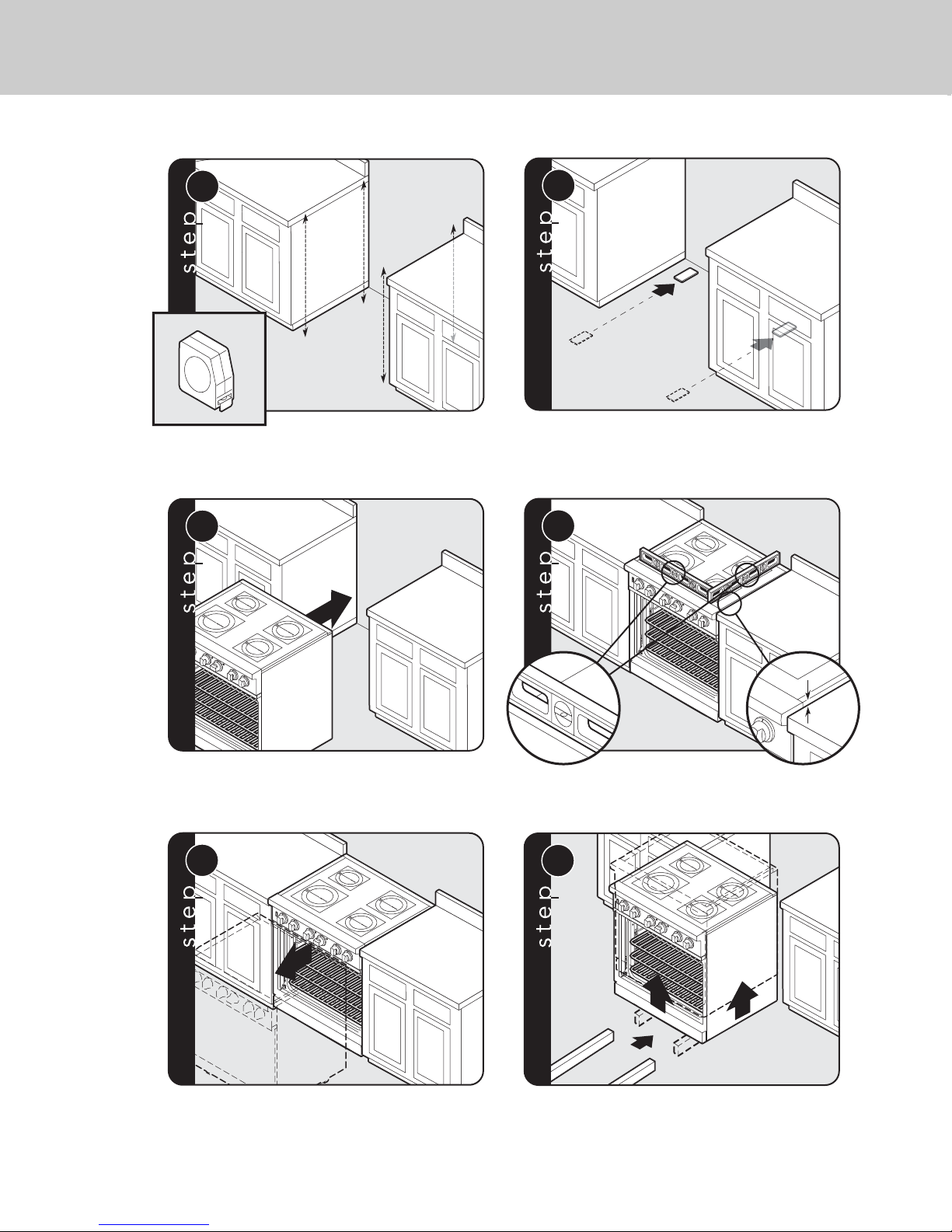
Measure the four corners in cutout area to
verify if flooring is level.
For uneven or sloped floors, level unit with
metal shims only, as the adjustment required may
exceed the thread available in the leg.
3
H
O
T
RE
A
R
F
R
O
NT
H
O
T
RE
A
R
F
RO
N
T
3/8”3/8”
(0.95 cm)(0.95
cm)
3/8”
(0.95 cm)
4
Move unit into opening.
Leveling/Adjustments/Alignment
5
H
O
T
R
E
A
R
F
R
O
NT
H
O
T
R
E
A
R
F
R
O
N
T
Check that unit is level side to
side and front to back. Side trim of the high corner
must be 3/8” (0.95 cm) above countertop.
If leveling is required, move unit out of opening.
6
1
2
1
H
O
T
R
E
A
R
F
R
O
N
T
H
O
T
R
E
A
R
F
RO
N
T
Lift unit and prop on wood blocks.
Page 21

21
7
H
O
T
R
E
A
R
F
R
O
NT
H
O
T
R
E
A
R
F
RO
N
T
Set the high corner of range so that the top of side trim is
3/8” (0.95 cm) above countertop. Level range to high corner.
Page 22
22
(A)
+1/2”
(1.3
cm)
3-5/8
”
(9.2 cm)
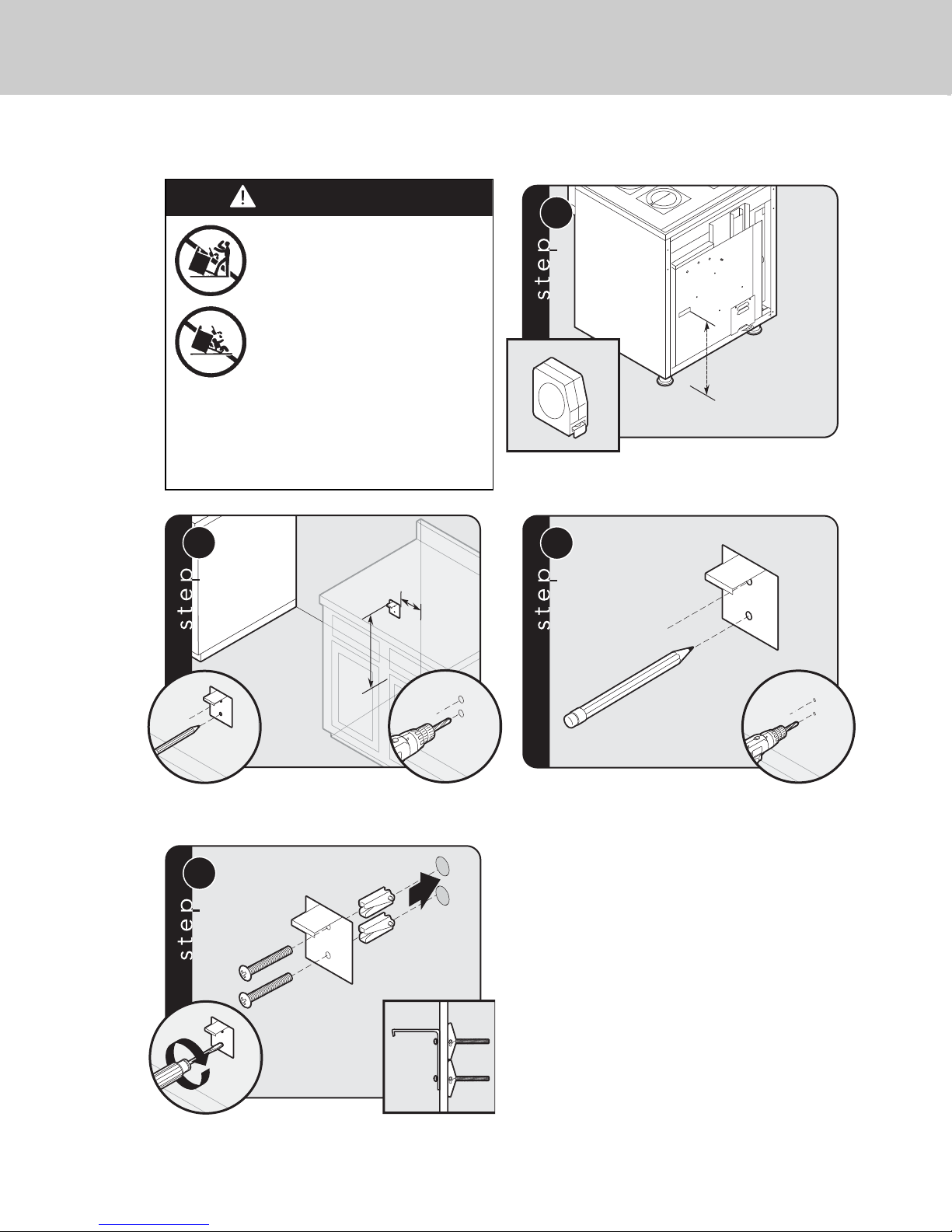
Measure from floor to bottom
of the anit-tip opening located on the back of range.
This will be measurement (A).
Locate anti-tip bracket on rear wall with the top left corner at
measurement (A) plus 1/2” (1.3 cm) from the floor and 3-5/8” (9.2 cm)
from where the right side of range (facing range) is to be located.
Mark and drill holes where bracket
will be located.
Anti-tip Device Installation - Wall Mount
WARNING
Tipping hazard.
To reduce the risk of the appliance
tipping, it must be secured by a
properly installed anti-tip bracket(s).
To make sure the bracket has been
installed properly, look behind the
range with a flashlight to verify
proper installation engaged in the
rear top left corner of the range.
• THIS RANGE CAN TIP.
• INJURIES TO PERSONS CAN RESULT.
• INSTALL ANTI-TIP DEVICE PACKED
WITH RANGE.
• SEE INSTALLATION INSTRUCTIONS.
1
2
4
Attach bracket with
mounting hardware provided.
1
(A)(A)
2
3
3
-5/8”
-5/8”
(9.2 cm)
(9.2 cm)
(A)
(A)
(1.3 cm)
(1.3 cm)
+1/2”
+1/2”
3
Page 23
23
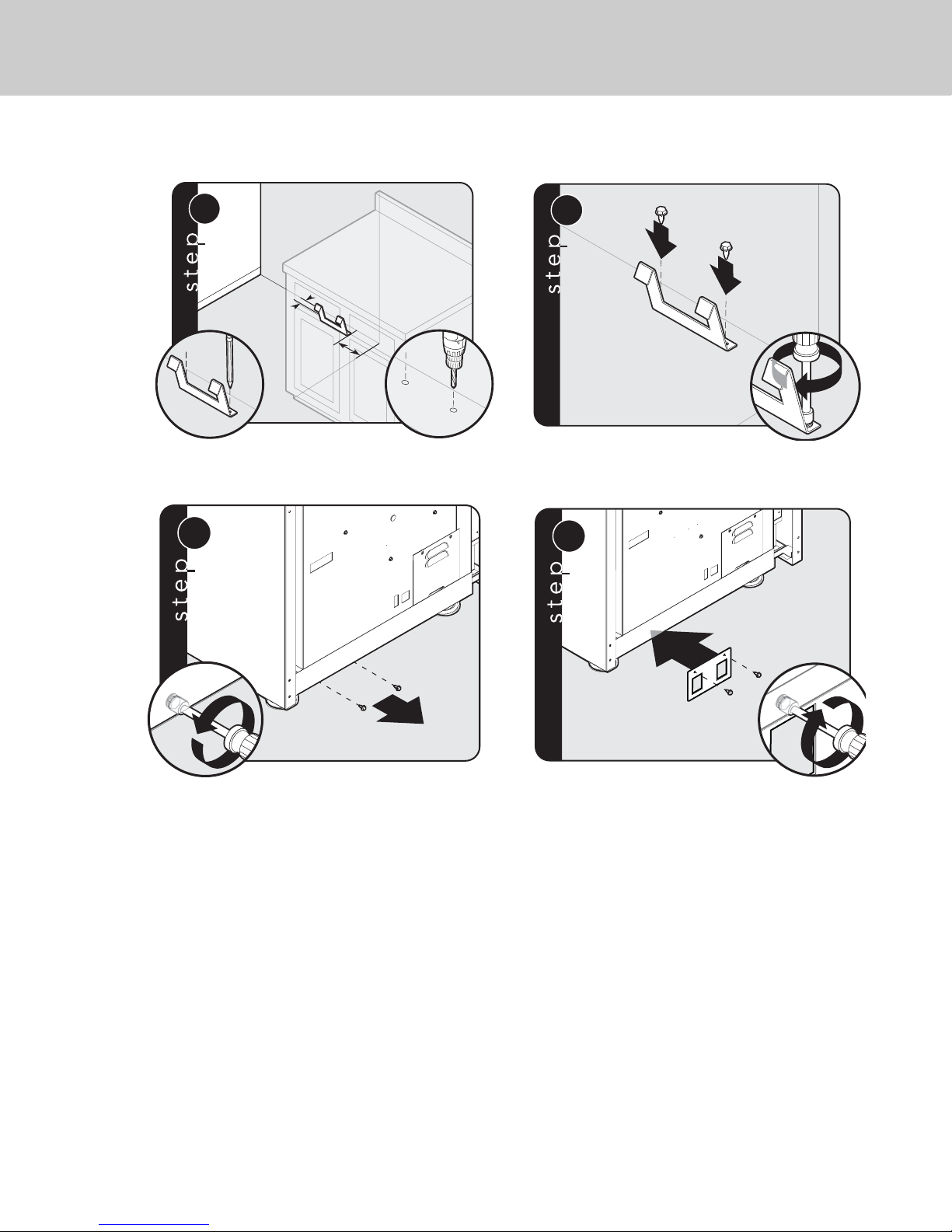
Anti-tip Device Installation - Floor Mount
8-1/2”
(21.6 cm
)
Ø
1
/8
”
(.3
2
cm)
1-1/2”
(3.8 cm)
1
1
2
2
2
1
x2
1
2
4
Locate anti-tip bracket hook on the floor 8-1/2” (21.6 cm) from side
cabinet and 1-1/2” (3.8 cm) from rear wall. Mark and
drill 1/8” (.32 cm) holes where bracket will be located.
Mount anti-tip bracket hook to floor
using screws provided.
Remove two screws from back of range.
Attach bracket to back of range using two screws.
1
1-1/2”
1-1/2”
(3.8 cm)
(3.8 cm)
8-1/2”
8-1/2”
(21.6 cm)
(21.6 cm)
Ø 1/8”
Ø 1/8”
(.32 cm)
(.32 cm)
3
Page 24
3/8”3/8”
(0.95 cm)(0.95
cm)
3/8
”
(0.95 cm)
3
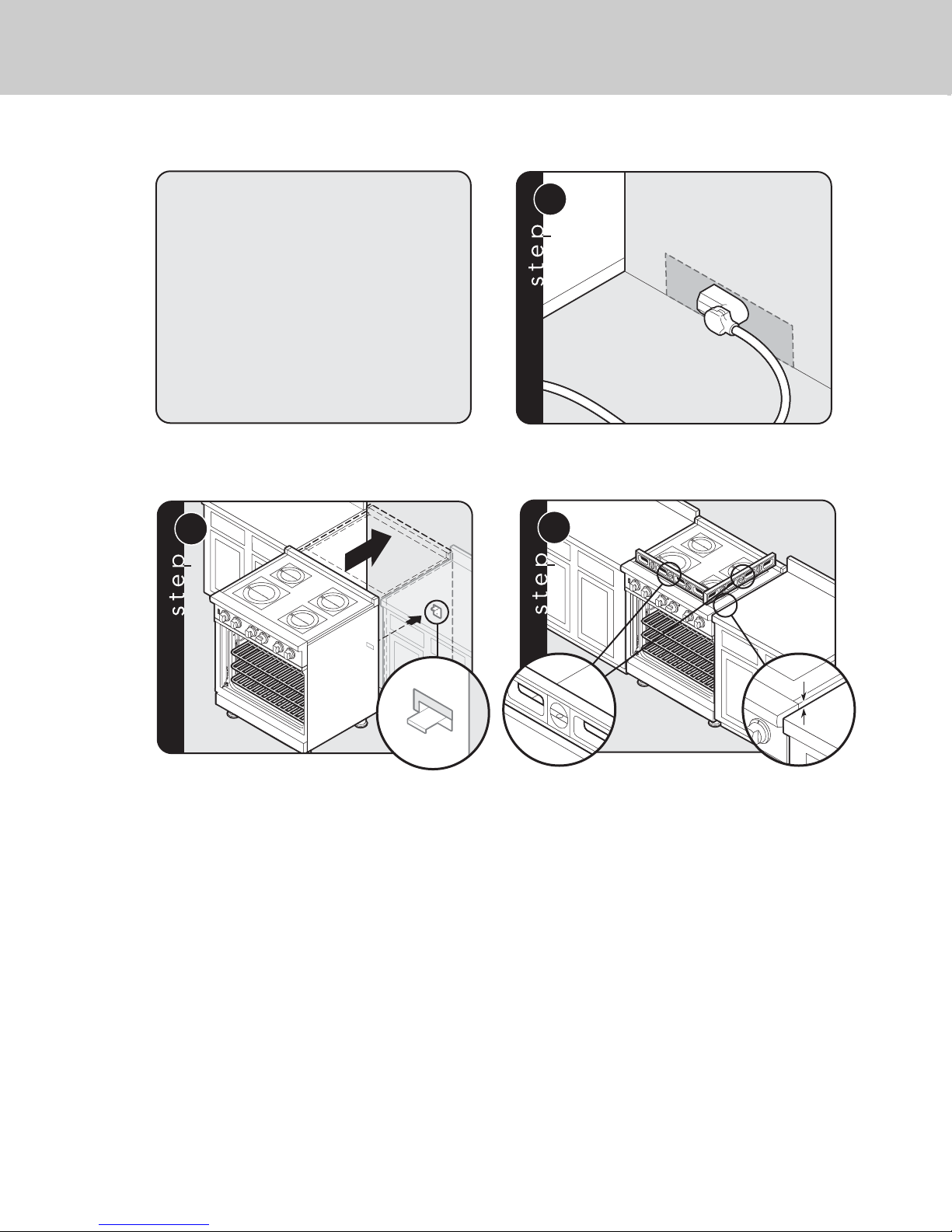
Check that unit is level side to side
and front to back. The side trim must be 3/8” (0.95 cm)
above countertop. If unit is not level repeat steps 5-7
of “Leveling/Adjustments/Alignment” section.
24
Note: Refer to range electrical
requirements section for proper
installation information.
Connect electrical in shaded area. See the “Electrical
Requirements” section for more information.
Final Installation
Slide range into place. Be sure anti-tip
bracket slides into the anti -tip opening.
2
1
H
O
R
T
E
A
R
F
R
H
O
N
O
T
R
T
E
A
R
F
R
O
N
T
Page 25
25
1
H
O
T
R
E
A
R
F
R
O
N
T
H
O
T
R
E
A
R
F
R
O
N
T
1
2
2
3
2
H
O
T
R
E
A
R
F
R
O
N
T
H
O
T
R
E
A
R
F
R
O
N
T
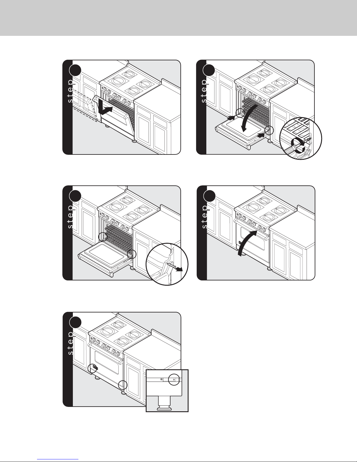
Reattach door to range.
Open door completely. Reattach hinge trim.
3
H
O
T
R
E
A
R
F
R
O
N
T
H
O
T
R
E
A
R
F
R
O
N
T
4
H
O
T
R
E
A
R
F
R
O
N
T
H
O
T
R
E
A
R
F
R
O
N
T
Remove pins from hole in hinges.
Close door.
5
H
O
T
R
E
A
R
F
R
O
N
T
H
O
T
R
E
A
R
F
R
O
N
T
If the door needs to be adjusted, loosen hinge trim screws (see step 2).
Adjust the screws located between the door and kickplate using a 5/32”
hex head allen wrench. After adjustment, tighten hinge trim screws.
Door Replacement and Adjustment
Page 26
26
Performance Checklist
A qualified installer should carry out the
following checks:
□
Check top surface elements
1. Starting with the left front element, turn
the corresponding knob to the Hi
position–Left front indicator should flash.
2. Place an induction compatible piece of
cookware onto the left front element–Left
front indicator should be solid.
3. Remove cookware and repeat steps for
other elements.
□
Check oven bake function—bake element
on full power, center and outside broil
elements at partial power.
□
Convection bake function—bake and broil
elements the same with the convection fan
on.
□
Check TruConvec™ function—TruConvec
element (behind convection fan cover) on
and convection fan on.
□ Check HI broil function–both broil
elements at full power.
□
Check LOW broil function—inner broil
element only.
□
Check convection broil function—both
broil elements at full power with convection
fan on.
□
Check self-clean function—door will lock
in approximately 30 seconds, the center
and outside broil elements will turn on and
the bake element will turn on at partial
power. Check broil elements through
window to make sure they are on, then
abort self-clean cycle to unlock door.
Final Preparation
• All stainless steel body parts should be
wiped with hot, soapy water and with a
liquid cleaner designed for this material.
If buildup occurs, DO NOT use steel wool,
abrasive cloths, cleansers, or powders!
If it is necessary to scrape stainless steel
to remove encrusted materials, soak with
hot, wet cloths to loosen the material, then
use a wool or nylon scraper. DO NOT use
a metal knife, spatula, or any other
material tool to scrape stainless steel!
Scratches are almost impossible to
remove.
NOTICE
When conducting performance test,
DO NOT run self-clean cycle for more
than 10 minutes with oven racks inside
oven. This could cause them to discolor
due to the high temperature required
for self-cleaning.
Page 27

27
Only authorized replacement parts may be used in performing service on the appliance.
All servicing should be referred to a qualified technician.
Contact Viking Range, LLC, 1-888-845-4641, for the nearest service parts distributor in your area
or write to:
VIKING RANGE, LLC
PREFERRED SERVICE
1803 Hwy 82W
Greenwood, Mississippi 38930 USA
Record the information indicated below. You will need it if service is ever
required. The model and serial number can be found by either tilting range
back or using a mirror to look underneath on the front edge of the bottom
base. A duplicate label is located on the back side of the range.
Model number
____________________________________________________________________________________
Serial number _____________________________________________________________________________________
Date of purchase __________________________________________________________________________________
Date installed ______________________________________________________________________________________
Dealer's name _____________________________________________________________________________________
Address ___________________________________________________________________________________________
These installation instructions should remain with the unit for future reference.
Service & Registration
Page 28

Viking Range, LLC
111 Front Street
Greenwood, Mississippi 38930 USA
(662) 455-1200
For product information, call 1-888-845-4641
or visit our web site at www.vikingrange.com in the US
or www.brigade.ca in Canada
058774-000 EN
(031516)
 Loading...