

Page 1
USE / INSTALLATION GUIDE
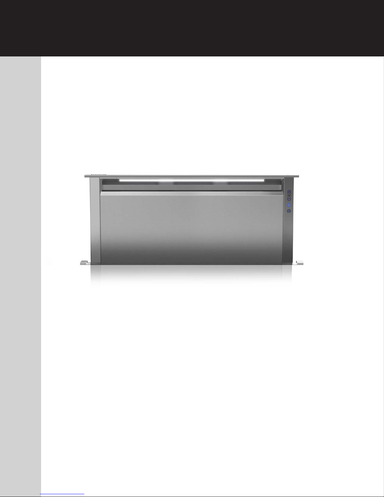
Rear Downdraft Ventilators
5 Series
Page 2
MODEL WIDTH BLOWER (purchased separately)
VDD5300/CVDD5300 30" W. VDVI600 Interior or VDVE900 Exterior
VDD5360/CVDD5360 36" W. VDVI600 Interior or VDVE900 Exterior
VDD5450/CVDD5450 45" W. VDVI600 Interior or VDVE900 Exterior, VDVE1200 Exterior
VDD5480/CVDD5480 48" W. VDVI600 Interior or VDVE900 Exterior, VDVE1200 Exterior
READ AND SAVE THESE INSTRUCTIONS
WARNING
TO REDUCE THE RISK OF FIRE, ELECTRIC SHOCK, OR INJURY
TO PERSONS, OBSERVE THE FOLLOWING:
1. Use this unit only in the manner intended by the manufacturer.
If you have questions, contact the manufacturer at the address
or telephone number in the warranty.
2. Before servicing or cleaning unit, switch power off at service
panel and lock the service disconnecting means to prevent
power from being switched on accidentally. When the service
disconnecting means cannot be locked, securely fasten a
prominent warning device, such as a tag, to the service panel.
3. Installation work and electrical wiring must be done by a
qualified person(s) in accordance with all applicable codes
and standards, including fire-rated construction codes and
standards.
4. Sufficient air is needed for proper combustion and exhausting
of gases through the flue (chimney) of fuel burning equipment
to prevent backdrafting. Follow the heating equipment
manufacturer’s guideline and safety standards such as those
published by the National Fire Protection Association (NFPA),
and the American Society for Heating, Refrigeration and
Air Conditioning Engineers (ASHRAE), and the local code
authorities.
5. When cutting or drilling into wall or ceiling, do not damage
electrical wiring and other hidden utilities.
6. Ducted fans must always be vented to the outdoors.
7. To reduce the risk of fire, use only metal ductwork.
8. Do not install this product with the activating switch directly
behind a burner or element. Minimum distance between the
switch and the edge of the burner should be 4 inches.
9. Loose-fitting or hanging clothing should never be worn when
operating this appliance. They may be ignited by burners/
elements on cooktop.
10. Children should not be left alone or unattended in the area
where this appliance is in use.
11. This unit must be grounded.
TO REDUCE THE RISK OF A RANGE TOP GREASE FIRE:
a) Never leave surface units unattended at high settings.
Boilovers cause smoking and greasy spillovers that may
ignite. Heat oils slowly on low or medium settings.
b) Always turn hood ON when cooking at high heat or when
cooking flaming foods.
c) Clean ventilating fans frequently. Grease should not be
allowed to accumulate on fan or filter.
d) Use proper pan size. Always use cookware appropriate
for the size of the surface element.
WARNING
TO REDUCE THE RISK OF INJURY TO PERSONS IN THE EVENT
OF A RANGE TOP GREASE FIRE, OBSERVE THE FOLLOWING
1. SMOTHER FLAMES with a close-fitting lid, cookie sheet, or
metal tray, then turn off the burner. BE CAREFUL TO
PREVENT BURNS. If the flames do not go out immedi-
ately, EVACUATE AND CALL THE FIRE DEPARTMENT.
2. NEVER PICK UP A FLAMING PAN - You may be burned.
3. DO NOT USE WATER, including wet dishcloths or towels - a
violent steam explosion will result.
4. Use an extinguisher ONLY if:
A. You know you have a Class ABC extinguisher, and you
already know how to operate it.
B. The fire is small and contained in the area where it
started.
C. The fire department is being called.
D. You can fight the fire with your back to an exit.
a
Based on “Kitchen Firesafety Tips” published by NFPA.
a
:
CAUTION
1. For indoor use only.
2. For general ventilating use only. Do not use to exhaust
hazardous or explosive materials and vapors.
3. To avoid motor bearing damage and noisy and/or unbalanced
impellers, keep drywall spray, construction dust, etc. off power
unit.
4. Clean filters and grease-laden surfaces frequently.
5. Do not repair or replace any part of this appliance unless
specifically recommended in this manual. All other servicing
should be done by a qualified technician.
6. Please read specification label on product for further
information and requirements.
7. To reduce the risk of fire and electric shock, install this downdraft
only with blower models shown below. Other blower models
cannot be substituted. (Blowers sold separately).
Flex Blower Model VDVI600
Exterior Blower Models VDVE900, VDVE1200
INSTALLER:
Save this manual for Electrical Inspector
and Homeowner to use.
2
Page 3
CONTENTS
These parts are included with your downdraft housing:
1 - Parts Bag containing:
2 - 2-in. Support Legs
2 - 4-in. Support Legs2 - Screws, 1/4-20 x .50 Hex Head
2 - Screws, 1/4-20 x .50 Hex Head
2 - Screws, #8-18 x .375 Phillipst
8 - Wood Screws, #10 x .50 Phillips Round Head
1 - Trim Kit
1 - Electrical Panel
2 - Support Brackets
PLANNING
Due to its flexible design, this downdraft system can be used to
exhaust airborne contaminants when cooking with a variety of gas or
electric cooking appliances - including cooktops, rangetops, slide-in
ranges and free-standing ranges.
It can be mounted in island, peninsula, or conventional wall location. The
blower (purchase separately) and electrical panel can be mounted to the
downdraft unit, inside the cabinet, or in a convenient remote location.
This unit can be easily installed following these basic steps:
V Cut out the countertop opening.
V Mount the unit in the cabinet.
V Install the blower and electrical panel.
V Connect the ductwork and electrical.
V Mount the trim/door.
V Install the cooking appliance.
Note: the high level of air flow of this appliance may effect the gas
flame on some types of gas cooktops. This is NORMAL and will cause
no harm, but can be corrected by lowering the speed of the blower.
ELECTRICAL SPECIFICATIONS
Model VDVI600 - Internal Flex:
/V!NV
Models VDVE900, VDVE1200 - Exterior
/V!NVA5L
TAKE MEASUREMENTS
1. Refer to the cooktop installation instructions for dimensions of
cooktop, countertop cut-out, and cabinet requirements. However,
it is recommended that oversized cabinets be used for easier
installation.
2. Cooktop depth can vary greatly from one to another. This may
cause the fit of these two appliances to be rather tight.
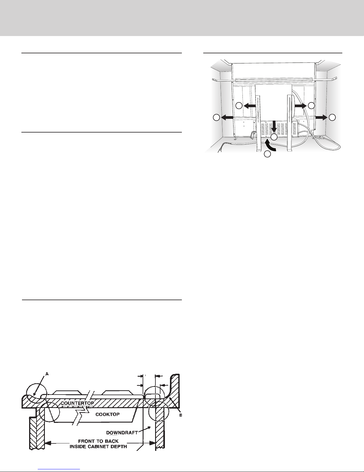
Pay special attention to the areas of potential interference highlighted
above. A countertop with (A) a raised lip and/or (B) a backsplash may not
allow enough flat countertop for a proper installation. Note that 2-3/4" of
flat countertop is required behind cooktop and that 2-1/2" is necessary
between the back edge of the cooktop and the inside of cabinet back.
2-1/2"
2-3/4"
PLAN THE DUCTWORK
HOUSING
FLEX
A
D
Remote blowers use 8" or 10" round remote discharge
*
plate instead of flex blower.
1. The downdraft blower system is designed for use with
8" round ductwork using a flex blower or 10" Round
ductwork using a remote blower. (Purchase blowers
separately.) Six (6) different discharge connections are
available - with side-to-side adjustment for accurate
alignment of ductwork:
A = 8" Round, Left Discharge out of Flex Blower
B = 8" Round, Right Discharge out of Flex Blower
C = 8" Round, Down Discharge out of Flex Blower
(Electrical Box to be mounted remotely)
D = 2" x 19¼", Left Discharge out of Housing
to Remote Blower or Flex Blower in remote
location. Use 2" x 19¼" to 8" round transition,
2" x 19¼" to 10" round transition, or 2" x 19¼"
ductwork as appropriate.
E = 2" x 19¼", Right Discharge out of Housing
to Remote Blower or Flex Blower in remote
location. Use 2" x 19¼" to 8" round transition,
2" x 19¼" to 10" round transition, or 2" x 19¼"
ductwork as appropriate.
F = 2" x 19¼", Rear Discharge out of Housing
to Remote Blower or Flex Blower in remote
location. Use 2" x 19¼" to 8" round transition,
2" x 19¼" to 10" round transition, or 2" x 19¼"
ductwork as appropriate.
2. For best performance: Choose the ducting option which
allows the shortest length of ductwork and a minimum
number of elbows and transitions. Check location of
floor joists, wall studs, electrical wiring or plumbing for
possible interference.
BLOWER
*
C
F
B
E
3
Page 4
PLAN CABINET CUTOUTS
(When using Remote Discharge Plate - Hole is
PREPARE THE DOWNDRAFT
CAUTION:
BEFORE CUTTING
HOLE IN CABINET
FOR DUCTWORK,
INSIDE
CABINET BACK
19¼” centered
2”
HOLE FOR 8” or
10” ROUND DUCT
FLUSH
7
/
6 ”
8
6 7/8"
FLUSH
2”
INSIDE
CABINET
FLOOR
COUNTERTOP
CABINET
BACK
SIDE
VIEW
INSTALLATION
CENTER LINE
HOLE
FOR
2” X 19¼”
DUCT
6”*
1½”
check for interference with
floor joists, wall studs,
electrical wiring, or plumbing.
26¾”
6”*
(*Adjustable 6” Left and 6” Right)
adjustable 6” Left and 6” Right from
Installation Center Line.)
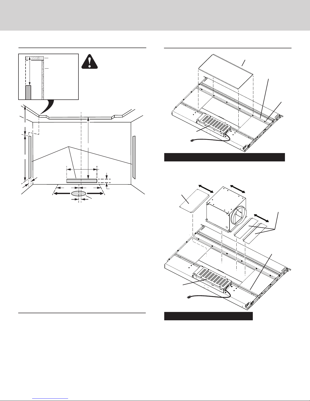
Use the dimensions in the above illustration to help plan how and
where to provide duct access through your cabinet. Generally,
1-7/8" x 19" rectangular duct will be used through left, right,
and back of cabinet - while 8" round duct will be used through
cabinet floor.
For left, right, or rear exhaust:
Allow at least 18" for transition and elbow or blower.
For left/right exhaust:
A 30" deep cabinet is recommended to align properly with
flex blower. Flex blower can be mounted to rear cabinet
wall or to a platform/frame (not provided) on the base of the
cabinet floor. (See flex blower instructions).
Cabinet depths of 24" to 30" are required - depending on the
type of cooking appliance.
PLAN THE WIRING
1. This downdraft blower using the Flex Blower (purchase
separately) draws 3.0 Amps and requires a 120 VAC, 60 Hz
circuit. If using a remote blower (purchase separately), the
system draws 6.0 Amps (max.) and requires a 120 VAC, 60
Hz circuit.
2. The unit has a 18 in. long power cord with a 3-pronged plug.
Plan to provide a grounded outlet in a location which will
allow the unit’s power cord to reach.
3. Install electrical box according to local codes.
4. The length of cable from the electrical box to the downdraft
is 20 in.
5. The length of blower (sold separately) cable to the electrical
box is 5 ft.
FRONT PANEL COVER
CLAMP
CHANNEL
Electrical panel
can be mounted
remotely.
Installations ducting through front panel opening only:
1. Place the downdraft on its back on a table or flat work surface.
2. Loosen the HEX NUTS on the CLAMP CHANNEL and remove
the FRONT PANEL COVER.
COVER
PLATE
FLEX
BLOWER
COVER PLATES
(included
with blower)
FRONT
PANEL
If blower
discharge is
down,
electrical
panel must be relocated.
See Step 6.
Installations using FLEX BLOWER only:
(Purchase Model VDVI600 Flex Blower separately.)
3. Determine its location on FRONT PANEL and whether it will
discharge to the left, right, or down.
Use a combination of COVER PLATES (3" and/or 6" wide) to
close the opening on side(s) of blower.
Slide the blower and cover plates between the LOWER
CHANNEL and the clamp channel. Tighten the hex nuts to
secure blower and panels in place.
4
(4-6) HEX
NUTS
LOWER
CHANNEL
Page 5
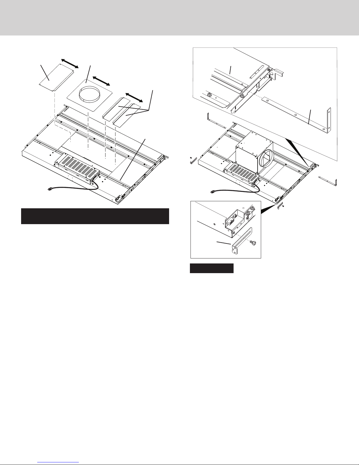
COVER PLATE
(included with
discharge plate)
8" OR 10" ROUND
REMOTE DISCHARGE
PLATE (Purchase Separatly)
COVER PLATES
(included with
discharge plate)
SLIDE
CHANNEL
UPPER
SUPPORT
BRACKET
FRONT
CHANNEL
PANEL
Installations using FLEX BLOWER (in remote location)
or REMOTE BLOWER only:
4. Use the REMOTE DISCHARGE PLATE and determine its
location on FRONT PANEL.
Use a combination of COVER PLATES (3" and/or 6" wide) to
close the opening on side(s) of remote discharge plate.
Slide the remote cover plate and cover plates between the
LOWER CHANNEL and the clamp channel. Tighten the hex
nuts to secure the plates in place.
LOWER
Flex Blower
shown
installed.
LONG OR
SHORT
SUPPORT
LEGS
HEX
SCREW
All Installations:
5. Slide UPPER SUPPORT BRACKETS into SLIDE CHANNEL at
top left and right of unit.
Attach LONG OR SHORT SUPPORT LEGS (depending upon
cabinet height) to bottom sides of unit with HEX SCREWS
provided. Do not tighten hex screws completely at this time.
5
Page 6
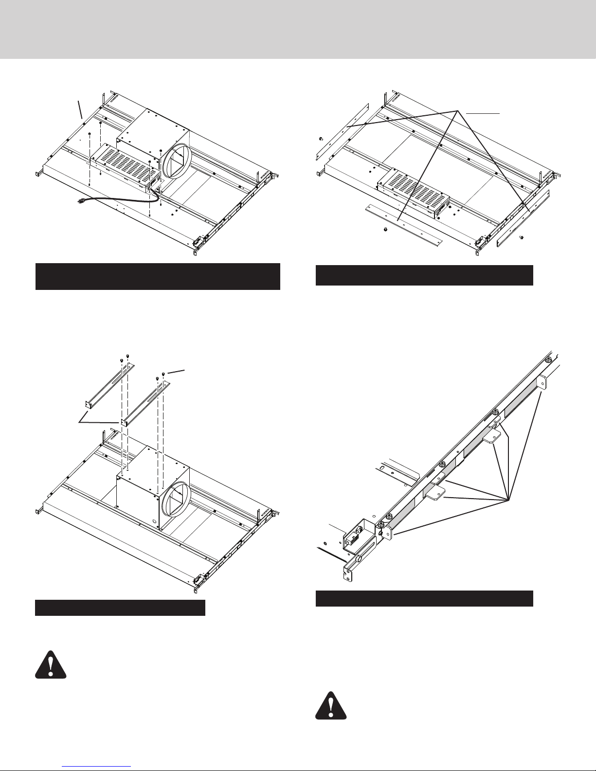
#8-32
HEX NUTS
RECTANGULAR
DISCHARGE COVERS
(Cut aluminum tape and remove
only one cover.)
This Front Panel
remains in place.
Installations where ELECTRICAL PANEL needs to be
mounted in a remote location only:
6. Remove (4) #8-32 HEX NUTS and ELECTRICAL PANEL. 5-ft.
extension cables (purchase separately) may be needed to
mount electrical panel in a remote location. Do not use more
that 2 extension cables.
(4) SCREWS
BLOWER
SUPPORT
LEGS
Installations ducting through left, right or rear only:
(Requires purchase of 1-7/8" x 19" to 8" or 10" round transition
and 1-7/8" x 19" rectangular duct cut to appropriate length.)
8. Use utility knife to cut aluminum tape and remove only one
RECTANGULAR DISCHARGE COVER.
(6) TABS
Ducting out right side of housing
shown.
Installations using FLEX BLOWER only:
7. Attach BLOWER SUPPORT LEGS with (4) SCREWS
provided.
CAUTION: If flex blower will be mounted remotely:
Do not use legs alone for support. It may be
necessary to add extra support for the flex blower.
Use mounting brackets supplied with the blower.
Installations ducting through left, right or rear only:
(Requires purchase of 1-7/8" x 19" to 8" or 10" round transition
and 1-7/8" x 19" rectangular duct cut to appropriate length.)
9. Beneath the rectangular discharge cover just removed - Use
a pliers to bend (6) TABS outward 90
0
. Use these tabs to
connect 2" x 19" rectangular ductwork or 2" x 19" to 8" or
10" round transition to housing when installing ductwork.
IMPORTANT: Regardless of blower placement/
exhaust, ensure that all seams are properly taped
- to make them secure and air-tight. This includes
6
seams/gaps between panels and/or on the blower.
Page 7
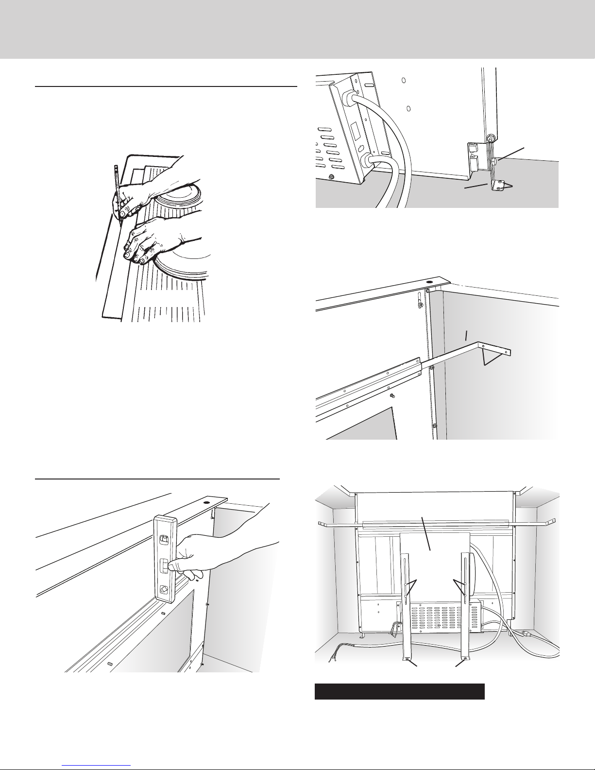
CUT COUNTERTOP OPENING
1. Lay out and cut the cooktop cut-out far enough FORWARD
so downdraft will fit behind it.
2. Set cooktop in place and slide it as far forward as possible
without exposing an gaps. Center and square it with edges
of countertop.
HEX
SCREW
(2) #10 X
.500 WOOD
SUPPORT
LEG
3. Extend SUPPORT LEGS and attach to bottom of cabinet with
(2) SCREWS through each leg. Tighten HEX SCREWS.
SCREWS
If cabinet bottom is removed:
Use blocks as spacers between floor and support
legs.
COOKTOP
Template against back
edge of cooktop.
3. Place the plastic template against the back flange of the cooktop or back edge of slide-in range countertop opening. Center
the template. Trace around template to mark the downdraft
opening.
4. Remove cooktop from countertop.
5. Cut downdraft opening. Be careful not to chip edges of countertop.
INSTALL HOUSING INTO
CABINET
UPPER
SUPPORT
BRACKET
(2) #10 X .500
WOOD SCREWS
4. Extend UPPER SUPPORT BRACKETS and attached to sides
of cabinet with (2) SCREWS through each bracket.
FLEX
BLOWER
(4) 1/4-20 X
.500
SCREWS
1. Remove cooktop.
2. Set housing into cabinet / countertop opening as far back as
possible and make sure it is level.
SCREWS
Installations using FLEX BLOWER only:
5. Loosen (4) SCREWS attaching BLOWER SUPPORT LEGS to
7
FLEX BLOWER. Extend legs and secure them to bottom of
cabinet with a SCREW through each bracket.
Page 8
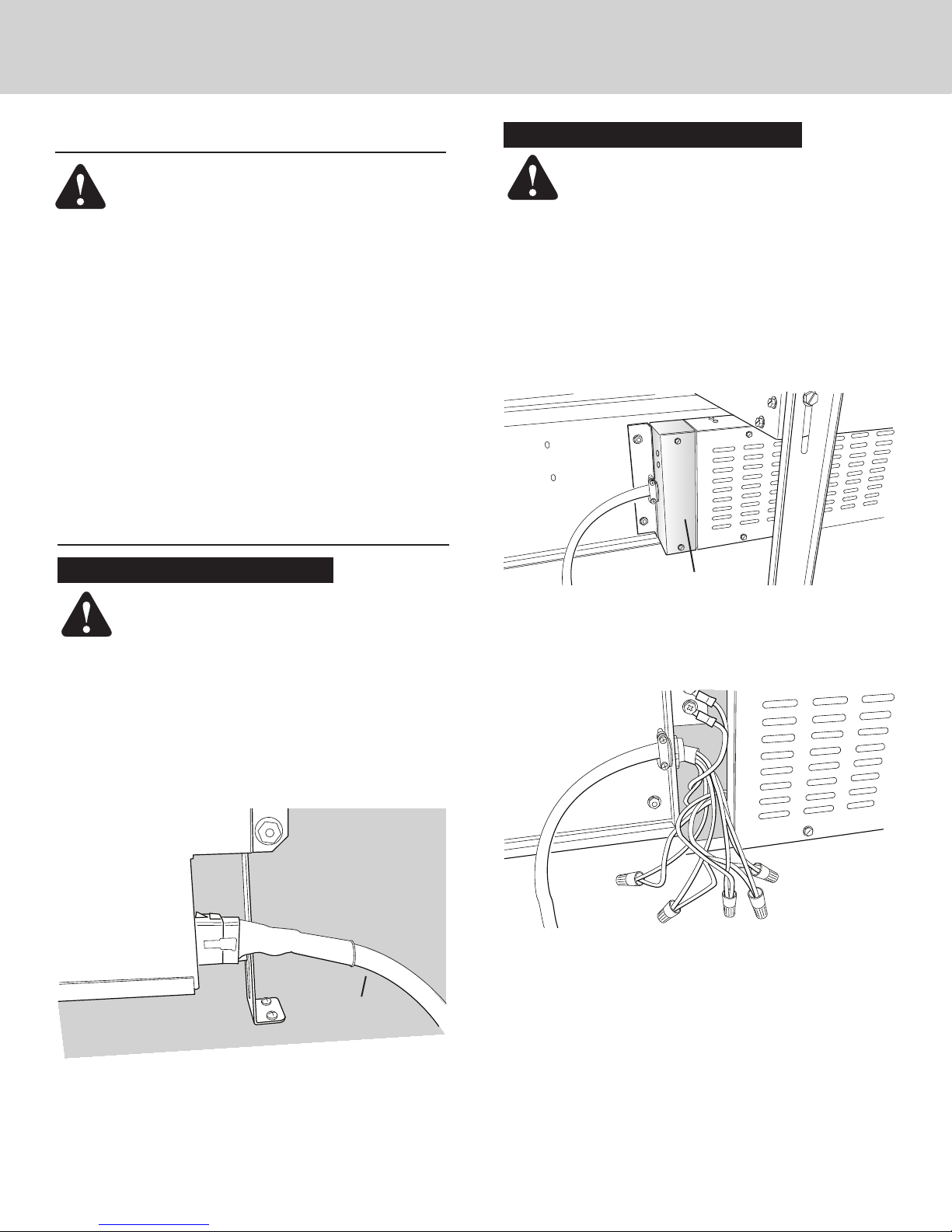
INSTALL DUCTWORK
Installations using REMOTE BLOWER only:
CAUTION: BEFORE CUTTING HOLE IN CABINET
FOR DUCTWORK, check for interference with floor
joists, wall studs, electrical wiring, or plumbing.
1. Cut hole in cabinet as well as holes in wall or floor as necessary.
2. Mount the roof or wall cap and work back towards the cabinet,
attaching all ductwork, elbows and transitions as previously
planned. Tape all ductwork connections to make them secure
and air tight.
3. Connect ductwork (and transition, if required) to down-
draft. If necessary, use (2) #8-18 x .375 phillips screws for
transition
INSTALL ELECTRICAL WIRING
Installations using FLEX BLOWER only:
CAUTION: All electrical wiring should be done by a
qualified person(s) in accordance with all applicable
codes and standards.
1. Mount a standard wiring box, with 3-pronged receptacle,
within reach of the downdraft's power cord.
2. Run appropriate power cable and connect it to receptacle.
3. Connect blower wires to wires in wiring box. Black to black,
white to white, blue to blue, orange to orange, gray to red,
and green to ground screw.
4. Replace wiring box cover.
CAUTION: All electrical wiring should be done by a
qualified person(s) in accordance with all applicable
codes and standards.
1. Mount a standard wiring box, with 3-pronged receptacle,
within reach of the downdraft's power cord.
2. Run appropriate power cable into cabinet and connect it to
electrical box and receptacle.
3. These exterior or in-line blower can be used:
Models VDVE900, VDVE1200 - Exterior
/V!NVA5L
WIRING BOX COVER
4. Run 2-wire plus ground power cable from the exterior or inline blower to wiring box on adaptor plate. Remove WIRING
BOX COVER.
RECEPTACLE
ELECTRICAL
CABINET BOTTOM
5. Plug ELECTRICAL PANEL CABLE into RECEPTACLE at
bottom/right of downdraft housing.
6. Plug the downdraft's power cord into the outlet. Make sure
that the power cord is routed away from the heat generated
by the cooktop.
PANEL CABLE
5. Connect blower wires to power cable from exterior or in-line
blower. Black to black, white to white, and green to ground
screw.
6. Replace wiring box cover.
7. Plug ELECTRICAL PANEL CABLE into RECEPTACLE at
bottom/right of downdraft housing.
8. Plug the downdraft's power cord into the outlet. Make sure
that the power cord is routed away from the heat generated
by the cooktop.
8
Page 9
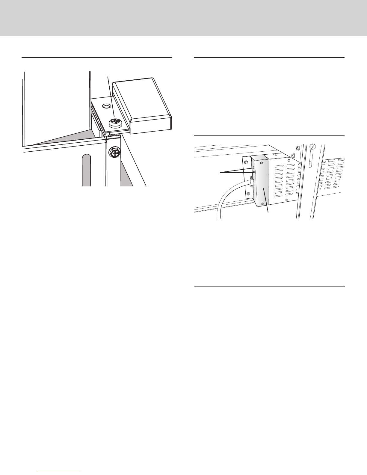
INSTALL FINISH TRIM
INSTALL COOKING APPLIANCE
SCREW
FINISH
CHIMNEY
DOWNDRAFT
HOUSING
1. Raise chimney and attach FINISH TRIM to top/left and top/
right of DOWNDRAFT HOUSING with screw provided.
TRIM
COUNTERTOP
1. Align the cooking appliance with downdraft and fasten
appliance in place following appliance instructions.
Note: Accurate alignment of cooking appliance and downdraft
is necessary to ensure that there is no interference when air vent
is raised and lowered. There should be a gap of 1/32" - 1/16"
between the back of the cooktop and the front of the downdraft
cover.
MAKE-UP AIR DAMPER (OPTIONAL)
MAKE-UP AIR
DAMPER
CONTACTS
WIRING
BOX
Connects to 2 CONTACTS on WIRING BOX.
Compatible with G6MD and G8MDdamper.
RANGE TRIM KIT (OPTIONAL)
Available for application with free-standing range - where gap
is present between back of range and downdraft.
9
Page 10
OPERATION
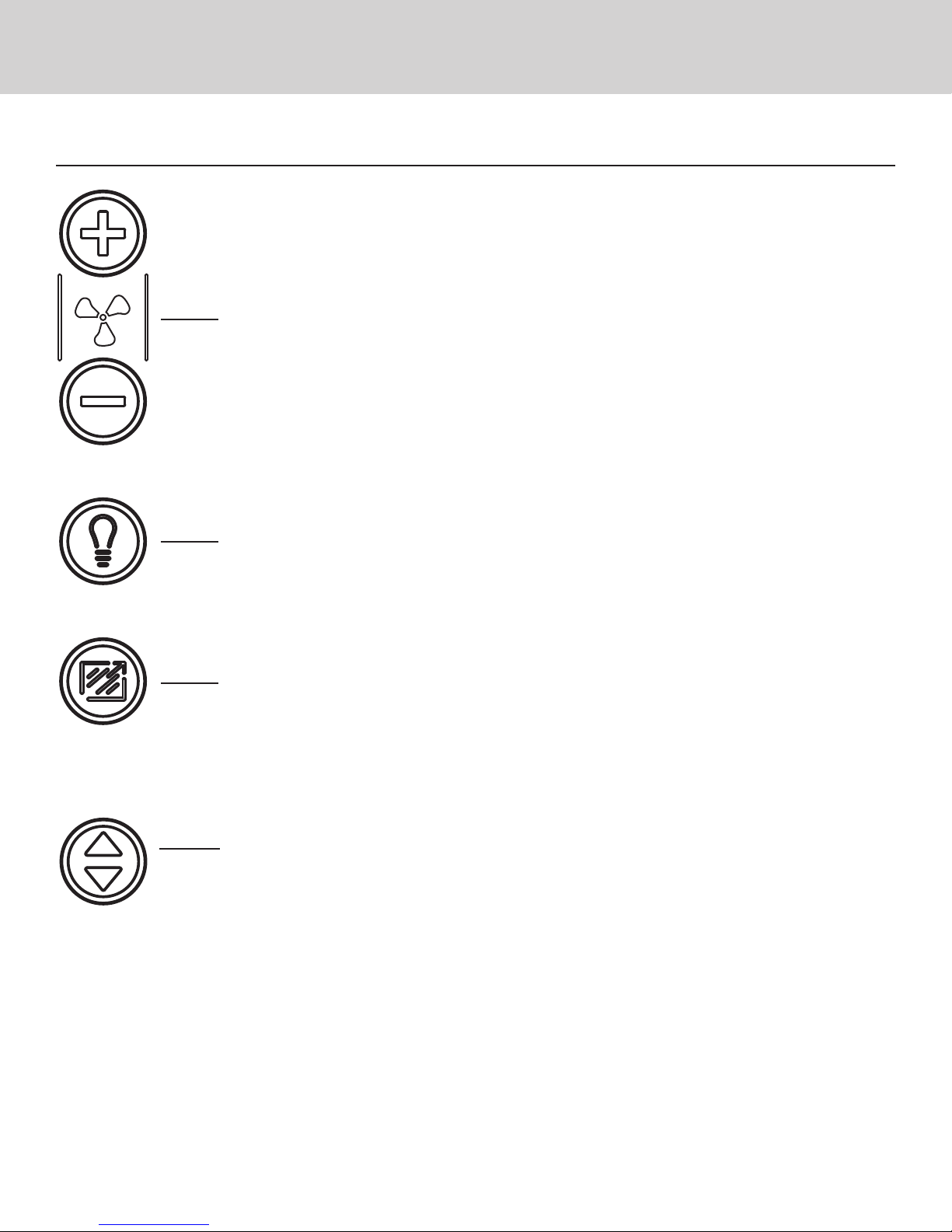
4-Speed Fan Speed Control
4-Speed Fan Speed Control
Press + button to increase fan speed.
Press - button to decrease fan speed.
After maximum speed is reached, press + button once more to
turn off fan.
2-Level Task Light
30-Hour Filter Clean Reminder
Up / Down
Button
2-Level Task Light
Press once for LOW setting.
Press 2x for HIGH setting. Icon will illuminate.
Press 3x to turn task light OFF.
30-Hour Filter Clean Reminder
After 30 hours of blower "ON" time, filter clean icon will blink
continuously.
To reset, touch and hold icon for 2 or more seconds. Indicator
will turn off.
Up / Down Button
To raise / lower chimney, touch up / down button. Any
feature that is active will shut off when chimney is retracting.
All functions will return to their previous settings when
chimney is raised.
Heat Sentry
When the operating temperature is too high, the fan speed will
increase to its highest setting to protect sensitive components.
The fan icon will blink and cannot be overridden until the
temperature reaches an acceptable level. The fan speed will
return to the previous setting and the icon will stop blinking.
10
Page 11
USE AND CARE
SERVICE INFORMATION
WARNING: Always disconnect electric power
supply before cleaning and/or servicing unit.
Always turn the downdraft blower on before you begin cooking
to establish an air flow in the kitchen. Let the blower run for a
few minutes to clean the air after you turn the cooktop off. This
will keep the whole kitchen cleaner and brighter.
Cleaning
Only authorized replacement parts may be used in performing
service on the appliance.
All servicing should be referred to a qualified technician.
Contact Viking Range, LLC, 1-888-(845-4641), for the nearest
service parts distributor in your area or write to:
VIKING RANGE, LLC
PREFERRED SERVICE
111 Front Street
Greenwood, Mississippi 38930 USA
Record the following information indicated below. You will
need it if service is ever required.
Model number __________________________________________
Serial number ___________________________________________
Date of purchase ________________________________________
Date installed ___________________________________________
Dealer’s name ___________________________________________
Address ________________________________________________
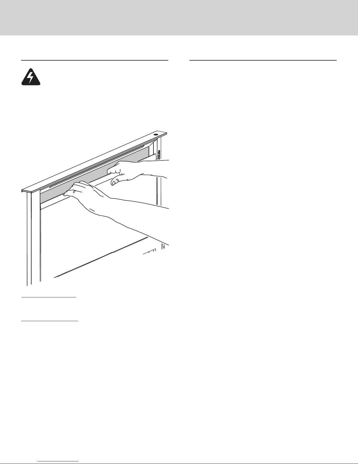
To clean grease filters: Remove front panel and take out the
(2) grease filters. Wash filters in a mild detergent solution or a
dishwasher. Replace filters before using downdraft.
To clean inside chimney: Remove filters. Pull front panel up and
out. Use a mild detergent. DO NOT USE ABRASIVE CLOTH,
STEEL WOOL PADS, OR SCOURING POWDERS. Replace front
panel and filters before using downdraft.
Servicing
It may be necessary to remove the downdraft blower system from
the cabinet in order to service components such as the blower
motor or air vent mechanism.
Disconnect power to the cooktop and remove it first. Reverse
the steps under “INSTALL HOUSING INTO CABINET” to remove
the downdraft from the cabinet.
________________________________________________________
These installation instructions should remain with the unit for
future reference.
11
Page 12

WARRANTY
DOWNDRAFT WARRANTY
Downdrafts and all of their component parts, except as detailed below*†, are warranted to be free from defective materials or workmanship in normal residential use for
a period of one (1) year from the date of original retail purchase. Viking Range, LLC, warrantor, agrees to repair or replace, at its option, any part which fails or is found
to be defective during the warranty period.
ONE YEAR FULL WARRANTY
*FULL NINETY (90) DAY COSMETIC WARRANTY: Product is warranted to be free from cosmetic defects in materials or workmanship (such as scratches on
stainless steel, paint/porcelain blemishes, etc.) for a period of ninety (90) days from the date of original retail purchase or closing date for new construction,
whichever period is longer. Any defects must be reported to the selling dealer within ninety (90) days from date of original retail purchase. Viking Range,
LLC uses high quality processes and materials available to produce all color finishes. However, slight color variation may be noticed because of the inherent
differences in painted parts and porcelain parts as well as differences in kitchen lighting, product locations, and other factors. Therefore, this warranty does
not apply to color variation attributable to such factors.
†FULL NINETY (90) DAY WARRANTY IN "RESIDENTIAL PLUS" APPLICATIONS: This full warranty applies to applications where use of the product
extends beyond normal residential use, but the warranty period for products used in such applications is ninety (90) days. Examples of applications covered
by this warranty are bed and breakfasts, fire stations, private clubs, churches, yachts, etc. Under this "Residential Plus" warranty, the product, its components
and accessories are warranted to be free from defective material or workmanship for a period of ninety (90) days from the date of original retail purchase.
This warranty excludes use of the product in all commercial locations such as restaurants, food service locations and institutional food service locations.
FIVE YEAR LIMITED WARRANTY ON VENTILATION MOTORS
Any ventilator motor which fails due to defective materials or workmanship (excluding cosmetic failures) in normal household use during the fourth through fifth year
from the date of original retail purchase will be repaired or replaced, free of charge for the part itself, with the owner paying all other costs, including labor. This does not
include ignition systems, burner bases, etc.
TERMS AND CONDITIONS
This warranty extends to the original purchaser of the product warranted hereunder and to each transferee owner of the product during the term of the warranty
and applies to products purchased and located in the United States, Mexico, and the Caribbean (excluding Cuba, Dominican Republic, and Haiti). Products must be
purchased in the country where service is requested. If the product or one of its component parts contains a defect or malfunction during the full warranty period after
a reasonable number of attempts by the warrantor to remedy the defect or malfunction, the owner is entitled to either a refund or replacement of the product or its
component part or parts. Replacement of a component part includes its free installation, except as specified under the limited warranty. Under the terms of this warranty,
service must be performed by a factory authorized Viking Range, LLC service agent or representative. Service will be provided during normal business hours, and labor
performed at overtime or premium rates shall not be covered by this warranty.
Owner shall be responsible for proper installation, providing reasonable and necessary maintenance,providing proof of purchase upon request, and making the
appliance reasonably accessible for service. The return of the Owner Registration Card is not a condition of warranty coverage. You should, however, return the Owner
Registration Card so that Viking Range, LLC can contact you should any question of safety arise which could affect you.
This warranty gives you specific legal rights, and you may also have other rights which may vary from jurisdiction to jurisdiction.
WHAT IS NOT COVERED BY THIS WARRANTY: This warranty shall not apply to damage resulting from abuse, failure to provide reasonable and necessary
maintenance, accident, delivery, negligence, natural disaster, loss of electrical power to the product for any reason, alteration, outdoor use, improper installation,
improper operation, or repair or service of the product by anyone other than an authorized Viking Range, LLC service agency or representative. This warranty does not
apply to commercial usage.
LIMITATION OF REMEDIES AND DURATION OF IMPLIED WARRANTYOWNER’S SOLE AND EXCLUSIVE REMEDY FOR A CLAIM OF ANY KIND WITH RESPECT
TO THISPRODUCT SHALL BE THE REMEDIES SET FORTH ABOVE. VIKING RANGE IS NOT RESPONSIBLE FORCONSEQUENTIAL OR INCIDENTAL DAMAGE,
INCLUDING BUT NOT LIMITED TO FOOD ORMEDICINE LOSS, DUE TO PRODUCT FAILURE, WHETHER ARISING OUT OF BREACH OF WARRANTY, BREACH OF
CONTRACT OR OTHERWISE. Some jurisdictions do not allow the exclusion or limitation of incidental or consequential damages, so the above limitation or exclusions
may not apply to you. ANY IMPLIED WARRANTIES OF MERCHANTABILITY OR FITNESS FOR A PARTICULAR PURPOSE APPLICABLE TO THIS PRODUCT ARE LIMITED
IN DURATION TO THE PERIOD OF COVERAGE OF THE APPLICABLE EXPRESS WRITTEN LIMITED WARRANTIES SET FORTH ABOVE. Some states do not allow
limitations on how long an implied warranty lasts, so the above limitation may not apply to you.
WARRANTY SERVICE
To o b t ai n w a rr a n ty se r v ic e , c on t a ct an a ut h or i ze d Vi k in g Ra n ge , LL C s e rv i c e a ge n t , o r V i ki n g R a ng e , L LC 1 11 Fr o nt S tr e et , G r ee n wo o d , M is s i ss i pp i 38 9 30 , ( 8 8 8) 84 5 -
4641. Provide model and serial number and date of original purchase or closing date for a new construction. For the name of your nearest authorized Viking Range, LLC
service agency, call Viking Range, LLC. IMPORTANT: Retain proof of original purchase to establish warranty period.
Specifications subject to change without notice.
VIKING RANGE, LLC
111 Front Street
Greenwood, Mississippi 38930 USA
(662) 455-1200
F21413A
99045252G
For more product information, call 1-888-845-4641, or visit our web site at
www.vikingrange.com in the US or brigade.ca in Canada
(070115)
 Loading...