

Page 1
VIKING RANGE CORPORATION
Please refer to Installation Instructions provided with bottom mount refrigerator/freezer for additional information.
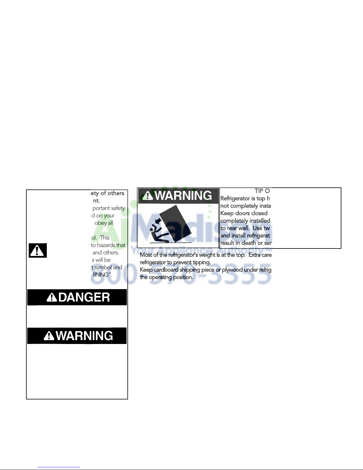
Most of the refrigerator’s weight is at the top. Extra care is needed when moving the
refrigerator to prevent tipping.
Keep cardboard shipping piece or plywood under refrigerator until it is install
ed in
the operating position.
Your safety and the safety of others
is very important.
You will be killed or seriously injur
ed if you
don’t follow instructions.
You can be killed or seriously injured if
you don’t follow inst
ructions.
TIP OVER HAZARD
Refrigerator is top heavy and tips easily when
not completely installed.
Keep doors
closed until refrigerator is
completely installed and secured with lag bolts
to rear wall. Use two
or more people to move
and install refrigerator. Failure to do so can
result in death or serious i
njury
INSTALLATION
Greenwood, Mississippi 38930 USA
111 Front Street
(662) 455-1200
INSTRUCTIONS
BUILT-IN BOTTOM MOUNT REFRIGERATOR/FREEZER
BRTGK72SS/PBRTGK72SS GRILLE KITS
(FOR PROFESSIONAL SERIES ONLY)
IMPORTANT - PLEASE READ AND FOLLOW
Make sure that incoming voltage is the same as unit rating. An electric rating plate specifying voltage, frequency, wattage,
amperage, and phase is attached to the product.
To reduce the risk of fire, electric shock, or injury to persons, installation work and electrical wiring must be done by qualified
people in accordance with all applicable codes and standards, including fire-rated construction.
The installer should leave these instructions with the consumer who should retain for local inspector’s use and for future
reference.
GENERAL INFORMATION
We have provided many important safety
messages in this manual and on your
appliance. Always read and obey all
safety messages.
This is the safety alert symbol. This
symbol alerts you to hazards that
can kill or hurt you and others.
All safety messages will be
preceded by the safety alert symbol and
the word “DANGER” or “WARNING”.
These words mean:
All safety messages will identify the
hazard, tell you how to reduce the chance
if injury, and tell you what can happen if
the instructions are not followed.
r
e
It is your responsibility to :
-comply with installation specifications and dimensions
-properly install refrigerator
-remove any moldings or decorative panels that prevent the refrigerator from
being serviced
-make sure that you have these materials, (not provided with the unit), which
are necessary for proper installation:
2 - 1/4” (6 mm) copper tubing with shutoff valve
2 - 1/4” (6mm) compression fitting
#8 x 3” (7.6 cm) wood screws (Longer screws may be required.)
BRTGK72SS - Qty 12
PBRTGK72SS - Qty 12
2 - saddle valves (do not use self-piercing valves).
n
e
-assure that floor will support refrigerator, door panels and contents,
(approximately 1200 lbs. [540 kg.])
-provide a properly grounded electrical outlet
-assure that location will permit appliance doors to open 90
o
minimum
Page 2

BASIC SPECIFICATIONS AND DIMENSIONS
DESCRIPTION BRTGK72SS PBRTGK72SS
(per unit)
VCBB363-DUAL INSTALLATION
Overall Width 72” (182.9 cm)
Overall Height from Bottom Min. 82 3/4” (210.2 cm)
Overall Depth from Rear To rear edge of side trim 22 3/16” (56.4 cm)
To front of top grille 24 11/16” (62.7 cm)
To end of handle bracket 27 1/4” (69.2 cm)
Cutout Width 71 1/2” (181.6 cm)
Cutout Height Min. 82 7/8” (210.3 cm)
Cutout Depth 24” (61.0 cm) min.
Electrical Requirements (2) - 115 volt, 60 Hz, 15 amp dedicated circuit; 3-wire cord with grounded 3-
prong plug attached to product.
Maximum Amp Usage 9.9 amps (per unit)
Inlet Water Requirements (2) - 1/4” copper tubing inlet waterline; minimum 20 psi; maximum 120 psi
Overall Interior Capacity
•Refrigerator 15.2 cu. ft. (.43 cu. meters)
•Freezer 5.1 cu. ft. (.14 cu. meters)
•Total Capacity 20.3 cu. ft. (.57 cu. meters)
Approximate Shipping Weight 575 lbs. (258.8 kg) - per unit
Max. 84 1/16” (213.5 cm)
Max. 84 1/16” (213.5 cm)
2
Page 3
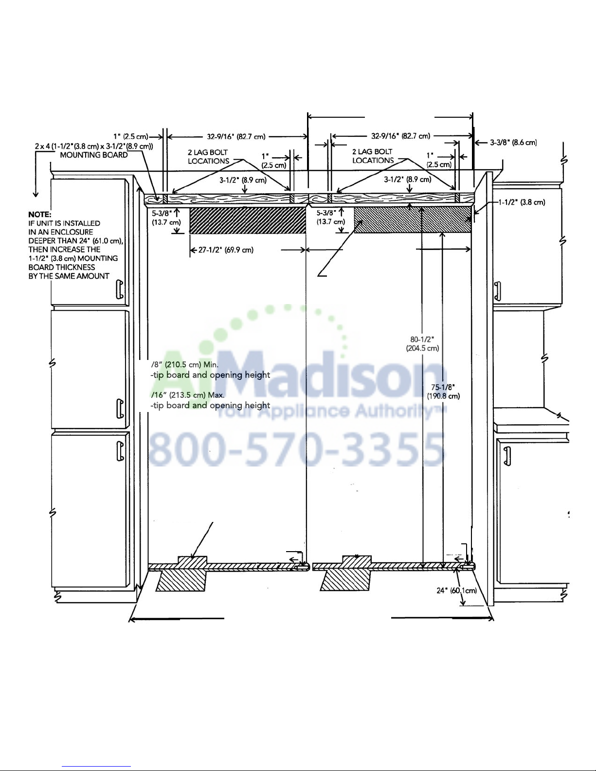
SITE PREPARATIONS AND CONSIDERATIONS
ELECTRICAL
RECEPTACLE
LOCATIONS
(SHADED AREAS)
1” (2.5 cm) TYP
FOUR (2 per unit)
82 7/8” (210.5 cm) Min.
anti-tip board and opening height
84 1/16” (213.5 cm) Max.
anti-tip board and opening height
71 1/2” (181.6 cm) FOR TWO
PROFESSIONAL STYLE 36” W.
BOTTOM MOUNT REFRIGERATORS
35 13/16” (91.5 cm)
39 3/16” (99.5 cm)
Water line
entry area
Water
line
Water
line
BRTGK72SS
PROFESSIONAL 36” W. BOTTOM MOUNT DUAL INSTALLATION,
CABINET OPENING DIMENSIONS
3
Page 4
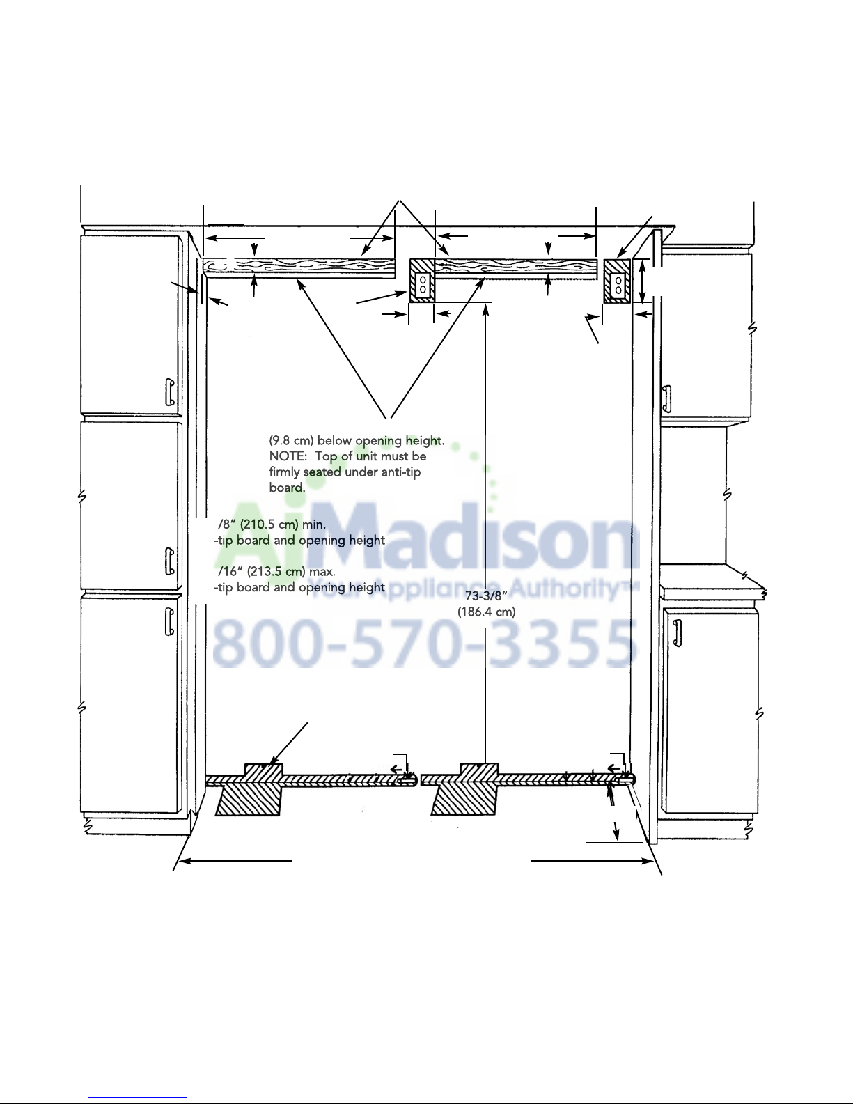
(2 per unit) 2” x 4” mounting boards (1-1/2” [3.8 cm] x 3-1/2” [8.9 cm])
NOTE: If unit is installe
d deeper than 24” (61.0 cm), then shim behind anit-tip bracket
thickness by the same amount.
29” (73.7 cm) 29” (73.7 cm)
3” (7.6 cm)
3-1/2”
(8.9 cm)
3-1/2”
(8.9 cm)
Bottom of anti-tip board is 3-7/8”
(9.8 cm) below opening height.
NOTE: Top of unit must be
firmly
seated under anti-tip
board.
6”
(15.2 cm)
6”
(15.2 cm)
9”
(22.2 cm)
Water line
entry area
82-7/8” (210.5 cm) min.
anti-tip board and opening height
84-1/16” (213.5 cm) max.
anti-tip board an
d opening height
73-3/8”
(186.4 cm)
SITE PREPARATIONS AND CONSIDERATIONS
71 1/2” (181.6 cm) FOR TWO
PROFESSIONAL STYLE 36” W.
BOTTOM MOUNT REFRIGERATORS
Water
Line
Water
Line
24” (61.0 cm)
PBRTGK72SS
PROFESSIONAL 36” W. BOTTOM MOUNT DUAL INSTALLATION,
CABINET OPENING DIMENSIONS
d
Electrical outlet
location
Electrical outlet
location
s
d
4
Page 5

Before moving the refrigerators in place, confirm the finished dimensions, electrical, and plumbing locations, minimum
door clearances, and door panel installations are accurate. (See Installation Instructions provided with refrigerators).
GRILLE ASSEMBLY/INSTALLATION
PROFESSIONAL MODEL
BRTGK72SS
(FOR PBRTGK72SS INSTALLATION - SKIP TO PAGE 9)
1. Position refrigerators in front of cutout.
2. Remove the top air grille assemblies from both of the refrigerators.
a. Remove the center grille blades by lifting up and pulling forward.
b. Remove the grille/end cap assembly by removing the four (4) screws in each black air duct.
c. Remove the black air ducts by removing the eight (8) screws on the right hinge model and the seven (7)
screws on the left hinge model. Save the air ducts for the 72” grille installation.
TOP
(4 Screws on top - 3 Screws on bottom)
TOP VIEW OF GRILLE ASSEMBLY
EXPLODED SIDE VIEW OF GRILLE ASSEMBLY
(4 Screws on top - 4 Screws on bottom)
SCREW HOLES
(15 Screws Used)
FRONT GRILLE ASSEMBLY
BLACK AIR DUCTS
5
Page 6

Left Hand
Cabinet Side Trim
Power
Switch
Showroom
Switch
3. Verify operation by plugging in
power cord. Power switch will
be shipped in the ON position
and showroom switch will be in
the ON position. (If showroom
switch is switched to the “OFF”
position, showroom mode is
engaged and power is shut off to
the compressor. This mode is for
showroom display only.)
4. Remove cabinet side trim that is mounted on the left hand side of the unit that is to be installed on the right side of
the installation. Replace this side trim with the “Z” shaped side trim and shim included in the full length grille kit.
6
Page 7

Cabinet Side Trim
(NOTE: “J” Shape)
Cabinet
Side Trim
(“Z” shape)
Anti-Tip
Lag Bolts
NOTE:
5. Remove cabinet side trim that is mounted on the right hand side of the unit that is to be installed on the left side
of the installation. Replace this side trim with the connection “J” shaped side trim and shim included in the full
length grille kit.
6. Place 1” (2.5 cm) spacer material on either left or right hand unit as shown on next page. The spacer material
should be located off the bottom of the unit and should not extend the entire height of the unit.
7. Engage the right hand unit’s left side trim into the J-shaped portion of the left side unit’s right side trim.
When leveling each refrigerator
and installing water connections, refer to
installation instructions provided with each
unit.
7
Page 8

8. Assemble air ducts to 72” grille using the supplied 15 screws removed in step 2c.
9. Remove 72” center grille blade by lifting up and pulling forward.
10. Insert air ducts and 72” grille into refrigerators. Screw air ducts into units with four screws per unit.
GRILLE ASSEMBLY
BLACK AIR DUCTS
REAR VIEW OF
GRILLE ASSEMBLY
TOP
SCREW HOLES
(16 Holes - 15 Screws)
8
Page 9

GRILLE ASSEMBLY/INSTALLATION
Before moving the refrigerators in place, confirm the finished dimensions, electrical, and plumbing locations, minimum
door clearances, and door panel installations are accurate. (See Installation Instructions provided with refrigerators).
REAR VIEW OF
GRILLE ASSEMBLY
TOP VIEW OF GRILLE ASSEMBLY
Power
Switch
Showroom
Switch
PROFESSIONAL MODEL
1. Position refrigerators in front of cutout.
2. Remove the top air grille assemblies from both of the units
a. Remove full length center grille blade by lifting up and pulling forward.
b. Remove the grille/end cap assembly by removing two (2) screws.
c. Remove grille brackets by removing four (4) screws in each grille assembly.
PBRTGK72SS
30 1/32” (76.3 cm)
3 3/8”
(8.6 cm)
3. Verify operation by plugging in
power cord. Power switch
will be shipped in the ON
position and showroom
switch will be in the ON
position. (If showroom switch
is switched to the “OFF”
position, showroom mode is
engaged and power is shut off
to the compressor. This mode
is for showroom display only.)
72” (182.9 cm)
30 7/8“ (78.4 cm)
4 7/32”
(10.7 cm)
9
Page 10

4. Remove cabinet side trim that is mounted on the left hand side of the unit that is to be installed on the right side
Cabinet Side Trim
(“Z” Shape)
Cabinet
Cabinet
Right Hand Door Unit
Left Hand Door Unit
1” (2.5 cm)
spacer
material
NOTE:
Cabinet Side Trim
(NOTE: “J” Shape)
of the installation. Replace this side trim with the “Z” shaped side trim and shim included in the full length grille
kit.
5. Remove cabinet side trim that is mounted on the right hand side of the unit that is to be installed on the left side
of the installation. Replace this side trim with the connection “J” shaped side trim and shim included in the full
length grille kit.
6. Place 1” (2.5 cm) spacer material on either left or right hand unit as shown on next page. The spacer material
should be located off the bottom of the unit and should not extend the entire height of the unit.
7. Engage the right hand unit’s left side trim into the J-shaped portion of the left side unit’s right side trim.
Double 2x4 mounting board fastened to wall at top of cabinet opening
When leveling each
refrigerator and installing water
connections, refer to installation
instructions provided with each unit.
10
Page 11

8. Assemble grille brackets to 72” grille using the 16 screws removed in step 2c.
9. Remove 72” center grille blade by lifting up and pulling forward.
10. Insert 72” grille into refrigerators. Screw 72” grille assembly into units with (4) screws removed in step 2b.
11
Page 12

111 Front Street • Greenwood, Mississippi 38930 USA • (662) 455-1200
Specifications subject to change without notice
F20083B (PS0306VR)
Viking Range Corporation
http://www.vikingrange.com
 Loading...