

Page 1
YYoouurr ssaaffeettyy aanndd tthhee ssaaffeettyy ooff ootthheerrss
iiss vveerryy iimmppoorrttaanntt..
We have provided many important safety
messages in this manual and on your
appliance. Always read and obey all
safety messages.
This is the safety alert symbol. This
symbol alerts you to hazards that
can kill or hurt you and others.
All safety messages will be
preceded by the safety alert symbol and
the word “DANGER” or “WARNING”.
These words mean:
YYoouu wwiillll bbee kkiilllleedd oorr sseerriioouussllyy iinnjjuurre
edd iiff yyoouu
ddoonn’’tt ffoollllooww iinnssttrruuccttiioonnss..
YYoouu ccaann bbee kkiilllleedd oorr sseerriioouussllyy iinnjjuurreedd iiff
yyoouu ddoonn’’tt ffoollllooww iinnssttr
ruuccttiioonnss..
All safety messages will identify the
hazard, tell you how to reduce the chance
if injury, and tell you what can happen if
the instructions are not followed.
INSTALLATION
INSTRUCTIONS
BUILT-IN BOTTOM MOUNT REFRIGERATOR/FREEZER
Retain for Future Reference
VIKING RANGE CORPORATION
111 Front Street
Greenwood, Mississippi 38930 USA
(662) 455-1200
IMPORTANT - PLEASE READ AND FOLLOW
Make sure that incoming voltage is the same as unit rating. An electric rating plate specifying voltage, frequency, wattage,
amperage, and phase is attached to the product.
To reduce the risk of fire, electric shock, or injury to persons, installation work and electrical wiring must be done by qualified
people in accordance with all applicable codes and standards, including fire-rated construction.
The installer should leave these instructions with the consumer who should retain them for local inspector’s use and for
future reference.
GENERAL INFORMATION
It is your responsibility to :
-comply with installation specifications and dimensions
-properly install unit
-remove any moldings or decorative panels that prevent the unit from being
serviced
-make sure that you have these materials (not provided with your unit),
which are necessary for proper installation:
1/4” (6 mm) copper tubing with shutoff valve
6 - #8 x 3” (7.6 cm) wood screws (Longer screws may be required.)
1 - Saddle valve (Do not use self-piercing feature of the valve)
-assure that floor will support unit, door panels and contents
(approximately 1200 pounds [540 kg])
-provide a properly grounded electrical outlet
-assure that location will permit appliance doors to open 90
o
minimum
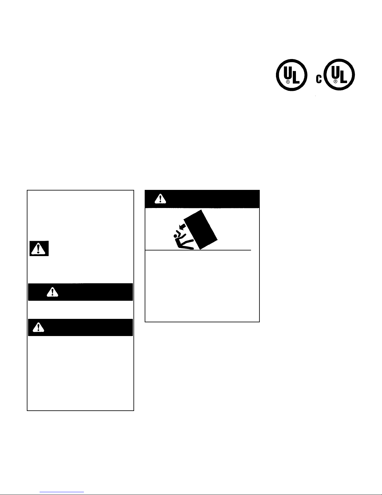
TTIIPP OOVVEERR HHAAZZAARRDD
AApppplliiaannccee iiss ttoopp hheeaavvyy aanndd ttiippss eeaassiillyy
wwhheenn nnoott ccoommpplleetteellyy iinnssttaalllleedd..
KKeeeepp ddoooorrss ccllo
osseedd uunnttiill aapppplliiaannccee iiss
ccoommpplleetteellyy iinnssttaalllleedd aanndd sseeccuurreedd ppeerr
iinnssttaallllaattiioonn iinnssttrruuccttiioonnss..
UUssee ttwwoo oorr m
moorree ppeeooppllee ttoo mmoovvee aanndd
iinnssttaallll aapppplliiaannccee.. FFaaiilluurree ttoo ddoo ssoo ccaann
rreessuulltt iinn ddeeaatthh oorr sseerriioouuss iinnjjuurryy..
MMoosstt ooff tthhee uunniitt’’ss wweeiigghhtt iiss aatt tthhee
ttoopp.. EExxttrraa ccaarree iiss nneeeeddeedd wwhheenn
mmoovviinngg tthhee uunniitt ttoo pprreevveenntt ttiippppiin
ngg..
UUssee ccaarrddbbooaarrdd sshhiippppiinngg mmaatteerriiaall oorr
ppllyywwoooodd uunnddeerr uunniitt uunnttiill iitt iiss
iinnssttaalllleedd iinn tthhee ooppeerraattiinngg ppoossi
ittiioonn ttoo
pprrootteecctt fflloooorr ssuurrffaaccee..
WARNING
DANGER
WARNING
Page 2
2
BASIC SPECIFICATIONS AND DIMENSIONS - PROFESSIONAL MODELS
DDEESSCCRRIIPPTTIIOONN VVCCBBBB336633
Overall Width 36” (91.5 cm)
Overall Height from Bottom Min. 82 3/4” (210.2 cm) to Max. 84 1/16” (213.5 cm)
Overall Depth from Rear To front edge of side trim 22 3/16” (56.4 cm)
To front of top grille 24 11/16” (62.7 cm)
To end of handle bracket 27 1/4” (69.2 cm)
Cutout Width 35 1/2” (90.2 cm)
Cutout Height 82 7/8” (210.5 cm) min.; 84 1/16” (213.5 cm) max.
Cutout Depth 24” (61.0 cm) min.
Electrical Requirements 115 volt, 60 Hz, 15 amp dedicated circuit; 3-wire cord with
grounded 3-prong plug attached to product.
Maximum Amp Usage 9.9 amps
Inlet Water 1/4” copper tubing inlet waterline;
Requirements minimum 20 psi; maximum 120 psi
Overall Interior Dimensions
•Refrigerator 15.2 cu. ft. (.43 cu. meters)
•Freezer 5.1 cu. ft. (.14 cu. meters)
•Total Capacity 20.3 cu. ft. (.57 cu. meters)
Approximate Shipping Weight 500 lbs. (227.3 kg)
BASIC SPECIFICATIONS AND DIMENSIONS - DESIGNER MODELS
DDEESSCCRRIIPPTTIIOONN DDDDBBBB336633
Overall Width 36” (91.5 cm)
Overall Height from Bottom Min. 82 3/4” (210.2 cm) to Max. 84 1/16” (213.5 cm)
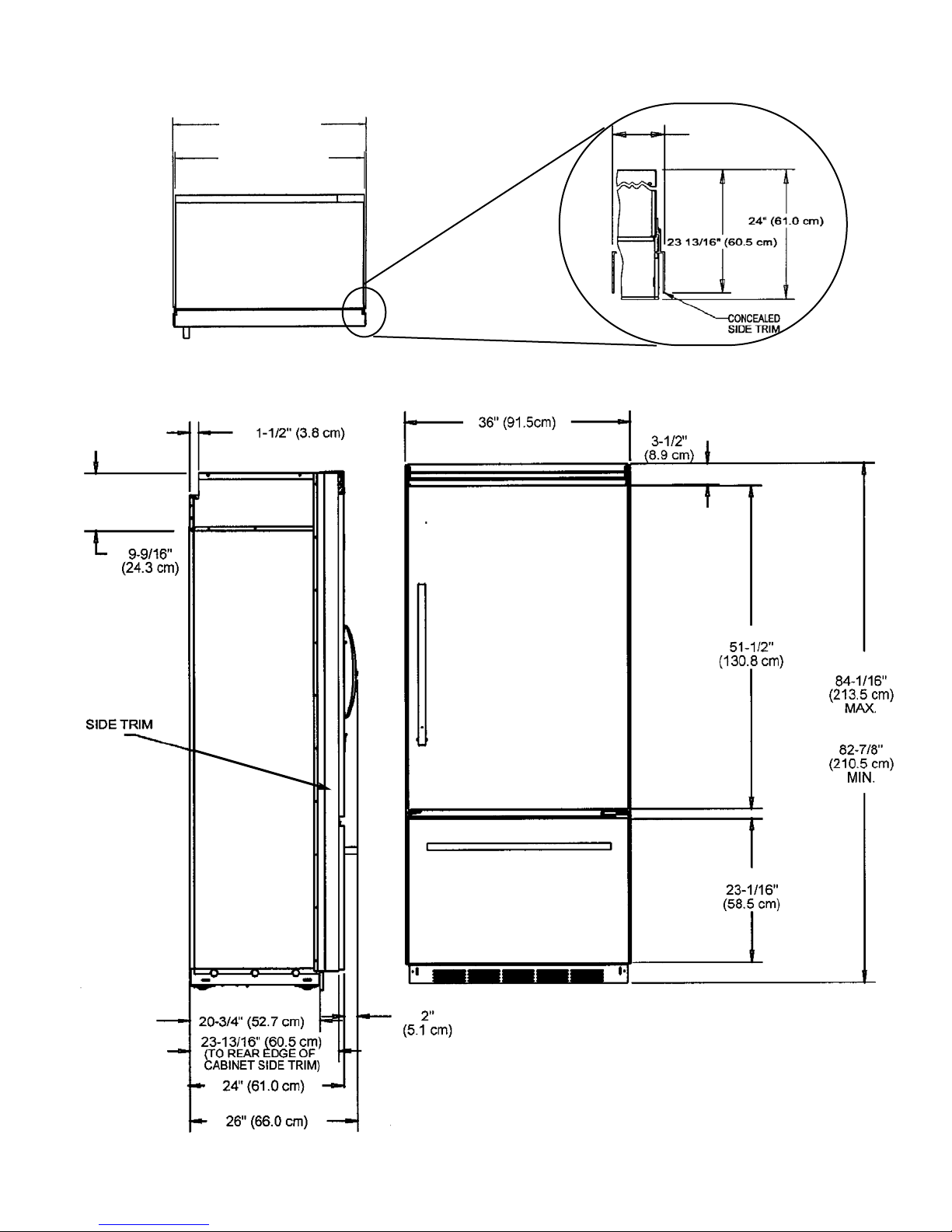
Overall Depth from Rear To rear edge of side trim 23 13/16” (60.5 cm)
To front of top grille 24” (61.0 cm)
To end of handle bracket 26” (66.0 cm)
Cutout Width 36” (91.5 cm)
Cutout Height 82 7/8” (210.5 cm) min.; 84 1/16” (213.5 cm) max.
Cutout Depth 24” (61.0 cm) min.
Electrical Requirements 115 volt, 60 Hz, 15 amp dedicated circuit; 3-wire cord with
grounded 3-prong plug attached to product.
Maximum Amp Usage 9.9 amps
Inlet Water 1/4” copper tubing inlet waterline;
Requirements minimum 20 psi; maximum 120 psi
Overall Interior Dimensions
•Refrigerator 15.2 cu. ft. (.43 cu. meters)
•Freezer 5.1 cu. ft. (.14 cu. meters)
•Total Capacity 20.3 cu. ft. (.57 cu. meters
Approximate Shipping Weight 500 lbs. (227.3 kg)
Page 3
3
BASIC SPECIFICATIONS AND DIMENSIONS - FULL OVERLAY MODELS
DDEESSCCRRIIPPTTIIOONN DDFFBBBB336633
Overall Width 36” (91.5 cm)
Overall Height from Bottom Min. 82 3/4” (210.2 cm) to Max. 84 1/16” (213.5 cm)
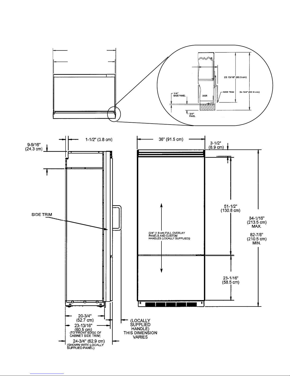
Overall Depth from Rear To rear edge of side trim 23 13/16” (60.5 cm)
To front of top grille 24 3/4” (62.9 cm)
To front edge of door trim 24” (61.0 cm)
Cutout Width 36” (91.5 cm)
Cutout Height 82 7/8” (210.5 cm) min.; 84 1/16” (213.5 cm) max.
Cutout Depth 24” (61.0 cm) min.*
Electrical Requirements 115 volt, 60 Hz, 15 amp dedicated circuit; 3-wire cord with
grounded 3-prong plug attached to product.
Maximum Amp Usage 9.9 amps
Inlet Water 1/4” copper tubing inlet waterline;
Requirements minimum 20 psi; maximum 120 psi
Overall Interior Dimensions
•Refrigerator 15.2 cu. ft. (.43 cu. meters)
•Freezer 5.1 cu. ft. (.14 cu. meters)
•Total Capacity 20.3 cu. ft. (.57 cu. meters
Approximate Shipping Weight 500 lbs. (227.3 kg)
**FFuullll oovveerrllaayy mmooddeellss ffiitt fflluusshh iinn 2255”” ((6633..55 ccmm)) ddeeeepp ccaabbiinneett ooppeenniinnggss.. TThheeyy ccaann bbee iinnssttaalllleedd iinn ssttaannddaarrdd 2244”” ((6611..00 ccmm))
ddeeeepp ooppeenniinnggss.. TThhee ddoooorr ffaacceess aanndd ttoopp ggrriillllee wwiillll pprroottrruuddee 33//44”” ((11..99 ccmm)) iinnttoo t
thhee rroooomm..
Page 4
4
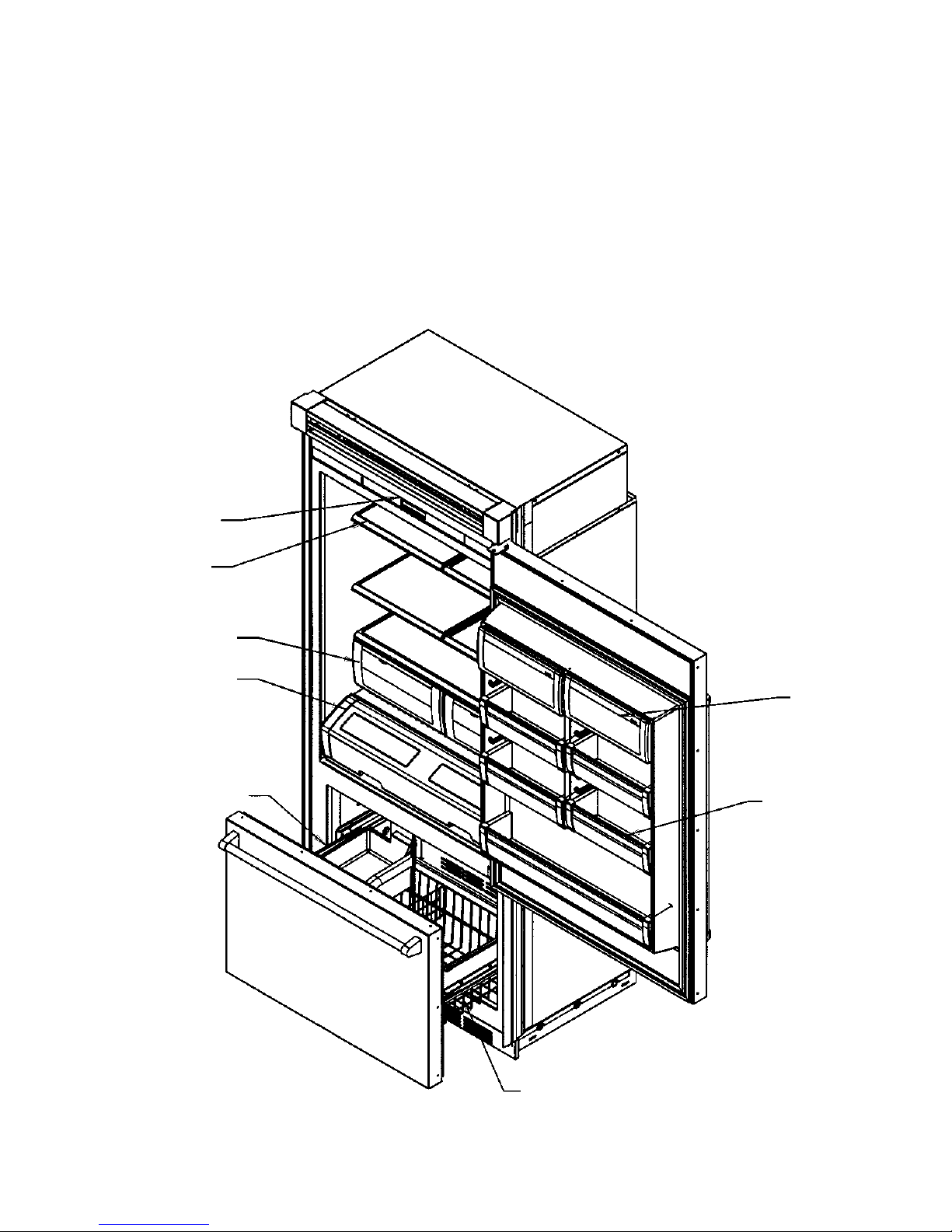
FEATURES OF YOUR REFRIGERATOR
1. Electronic Controls
2. Spillproof Shelves (5)
3. Moisture Control Produce Drawers (2)
4. Meat Savor
TM
/Produce Drawer (1)
5. Ice Bucket (1)
6. Dairy Compartments (2)
7. Door Bins (5)
8. Wire Freezer Baskets (2)
77
66
88
55
44
33
22
11
Page 5
5
SITE PREPARATIONS AND CONSIDERATIONS
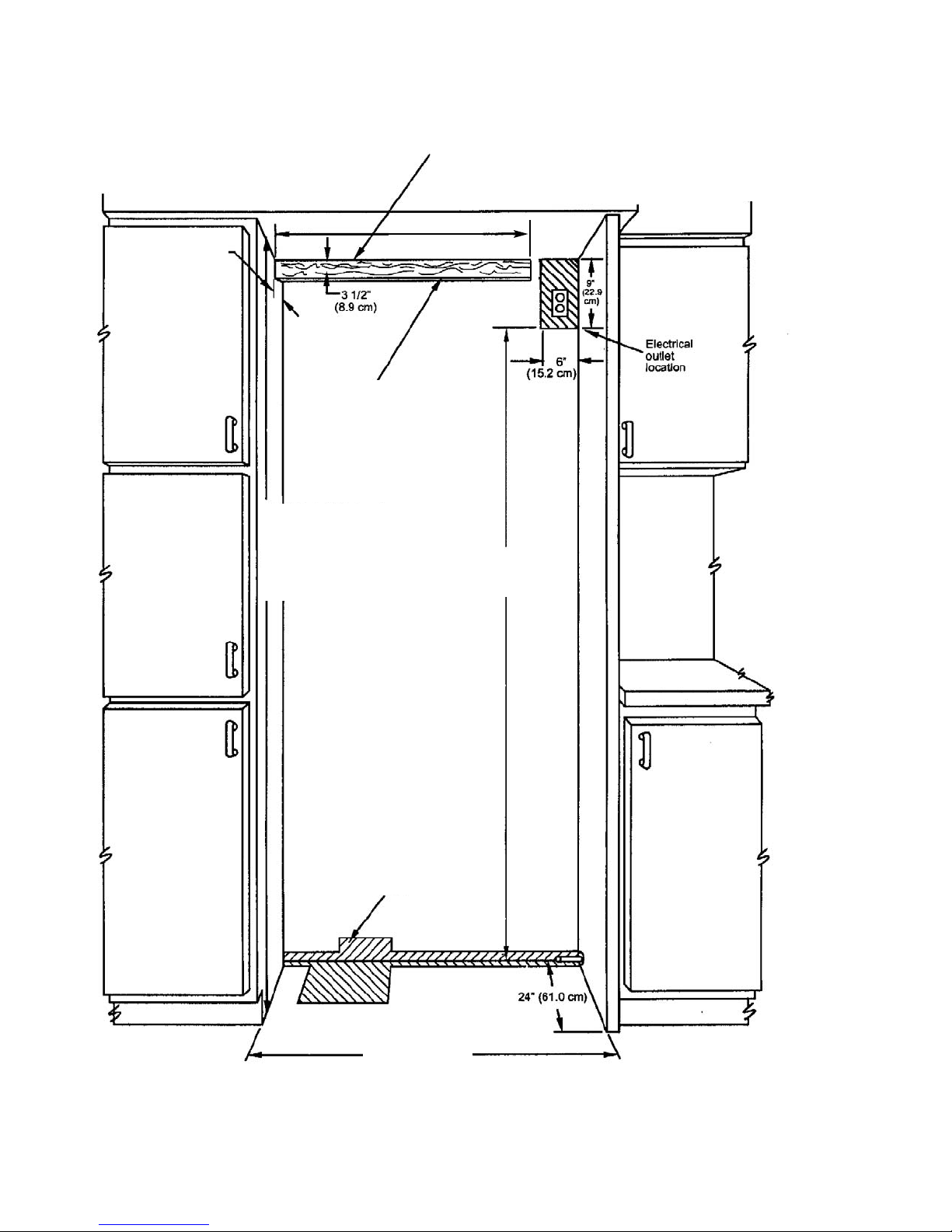
PROFESSIONAL MODEL BOTTOM MOUNT REFRIGERATOR/FREEZER
CABINET OPENING DIMENSIONS
((22)) 22””xx44”” MMoouunnttiinngg bbooaarrdd
((11 11//22”” [[33..88 ccmm]] xx 33 11//22”” [[88..99 ccmm]]))
NNoottee:: IIff uunniitt iiss iinnssttaalllleedd ddeeeeppeerr tthhaan
n 2244”” ((6611..00 ccmm)),, tthheenn sshhiimm bbeehhiinndd tthhee
aannttii--ttiipp bbrraacckkeett tthhiicckknneessss bbyy tthhee ssaammee aammoouunntt..
33””
((77..66 ccmm))
3355--11//22”” ((9900..22 ccmm))
2299””
((7733..77 ccmm))
7733 33//88””
((118866..44 ccmm))
8822 77//88”” ((221100..55 ccmm)) mmiinn..
aannttii--ttiipp bbooaarrdd aanndd ooppeenniinngg hheeiigghhtt
8844 11//1166”” ((221133..55)) mmaaxx..
aannttii--ttiipp bbooaarrdd aanndd o
oppeenniinngg hheeiigghhtt
BBoottttoomm ooff aannttii--ttiipp bbooaarrdd iiss
33 77//88”” ((99..88 ccmm)) bbeellooww ooppeenniinngg
hheeiigghhtt..
NNOOTTEE:: TToopp ooff uunniitt mmuusstt bbee ffiirrmmllyy
s
seeaatteedd uunnddeerr aannttii--ttiipp bbooaarrdd..
WWaatteerr lliinnee eennttrryy aarreeaa
((AAllll FFrreeeezzeerr oonnllyy))
Page 6
6
SITE PREPARATIONS AND CONSIDERATIONS
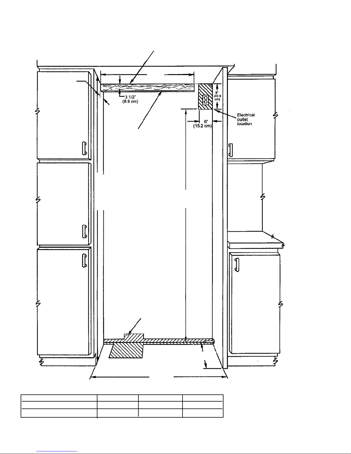
DESIGNER/FULL OVERLAY MODEL BOTTOM MOUNT REFRIGERATOR/FREEZER
CABINET OPENING DIMENSIONS
((11)) 22””xx44”” MMoouunnttiinngg bbooaarrdd ((11 11//22”” [[33..88 ccmm]] xx 33 11//22”” [[88..99 ccmm]]))
NNoottee:: IIff uunniitt iiss iinnssttaalllleedd ddeeeeppeerr tthhaan
n 2244”” ((6611..00 ccmm)),, tthheenn sshhiimm bbeehhiinndd aannttII--ttiipp
bbrraacckkeett tthhiicckknneessss bbyy tthhee ssaammee aammoouunntt
BB
AA BB CC**
36” W. Designer 29” (73.7 cm) 36” (91.5 cm) 24” (61.0 cm)
36” W. Full Overlay 29” (73.7 cm) 36” (91.5 cm) 25” (63.5 cm)
AA
CC**
*Full overlay models fit flush in 25”
(63.5 cm) deep cabinet openings. They
can be installed in standard 24” (61.0
cm) deep openings. The door faces
and top grille will protrude 3/4” (1.9 cm)
into the room.
11--11//22””
((33..88 ccmm))
7733 33//88””
((118866..44 ccmm))
8822 77//88”” ((221100..55 ccmm)) mmiinn..
aannttii--ttiipp bbooaarrdd aanndd ooppeenniinngg hheeiigghhtt
8844 11//1166”” ((221133..55)) mmaaxx..
aannttii--ttiipp bbooaarrdd aanndd o
oppeenniinngg hheeiigghhtt
BBoottttoomm ooff aannttii--ttiipp bbooaarrdd iiss
33 77//88”” ((99..88 ccmm)) bbeellooww ooppeenniinngg
hheeiigghhtt..
NNOOTTEE:: TToopp ooff uunniitt mmuusstt bbee ffiirrmmllyy
s
seeaatteedd uunnddeerr aannttii--ttiipp bbooaarrdd..
WWaatteerr lliinnee eennttrryy aarreeaa
((AAllll FFrreeeezzeerr oonnllyy))
Page 7
7
WATER SUPPLY REQUIREMENTS
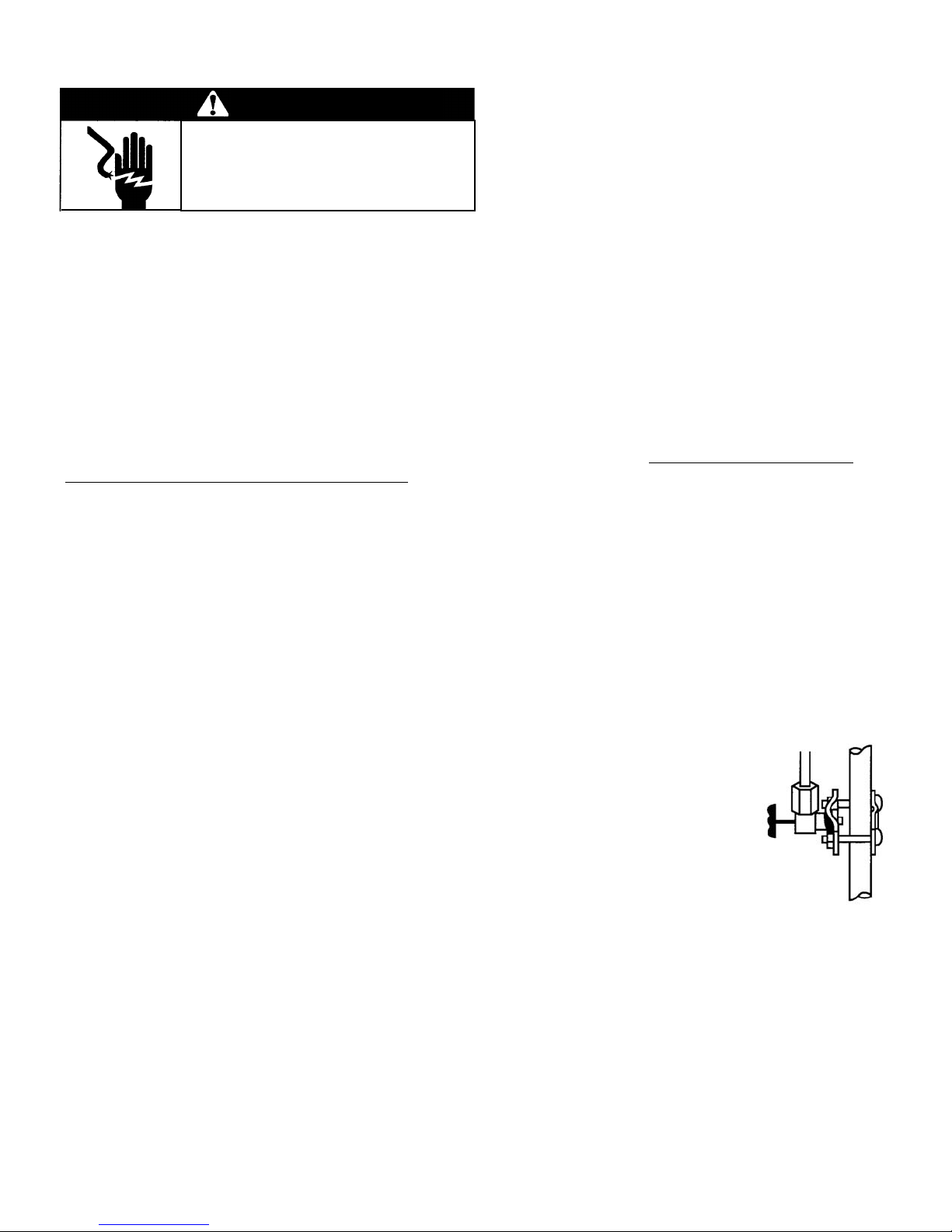
EELLEECCTTRRIICCAALL SSHHOOCCKK HHAAZZAARRDD
SSoommee wwaatteerr mmaayy rreemmaaiinn iinn lliinnee.. EElleeccttrriicc
ddrriillll mmuusstt bbee ggrroouunnddeedd ttoo pprreevveenntt sseevveerree oorr
lleetthhaall sshhoocckk iiff wwaatteerr iiss iinn lliinnee aanndd eenntteerrss ddrriillll
dduurriinngg uussee..
UUssee oonnllyy 11//44”” ((66 mmmm)) ccooppppeerr ttuubbiinngg ffoorr wwaatteerr lliinnee.. DDoo
NNoott iinnssttaallll ccooppppeerr ttuubbiinngg iinn aarreeaa wwhheerree tteemmppeer
raattuurreess
ddrroopp bbeellooww 3355
oo
FF ((11..77ooCC)).. BBeeffoorree aattttaacchhiinngg ccooppppeerr ttuubbiinngg
ttoo rreeffrriiggeerraattoorr,, fflluusshh aatt lleeaasstt 22 qquuaarrttss ((11..99 LL)) ooff wwaatteerr
tthhrroouuggh
h tthhee ccooppppeerr ttuubbiinngg aanndd iinnttoo aa bbuucckkeett ttoo rreemmoovvee
aannyy ppaarrttiicclleess iinn tthhee wwaatteerr lliinnee..
••VViikkiinngg RRaannggee CCoorrppoorraattiioonn iiss nnoott rreessppoonnssiibbllee ffoorr pprrooppeerrttyy ddaammaaggee dduuee ttoo iimmpprrooppeerr iinnssttaallllaattiioonn oorr wwaatteerr ccoonnnneeccttiioonn..
•Connect 1/4” (6mm) flexible copper tubing to household plumbing in compliance with local codes and ordinances.
•Length of copper tubing must reach from water supply connection to refrigerator connection with an additional length
to facilitate moving the refrigerator out of enclosure for cleaning or service. Tubing should be soft instead of rigid and
ends should be free of burrs.
•Copper tubing route must be above 35oF (1.7oC) to prevent water line from freezing.
••DDoo nnoott uussee ppllaassttiicc wwaatteerr lliinneess..
••DDoo nnoott uussee tthhee sseellff--ppiieerrcciinngg ffeeaattuurree ooff aa ssa
addddllee vvaallvvee..
The hole made by the piercing lance is too small for the water
flow rate required by the ice maker. To use a saddle valve, follow the instructions below located under “To rough in
water line” on how to pre-drill a 3/16” (4.5 mm) diameter hole.
•If saddle valve is not used, place a separate shut-off valve in an easily accessible location between water supply and
refrigerator. Do not locate shut-off valve behind refrigerator.
•The installation of Viking refrigerators with an reverse osmosis system is acceptable
aass lloonngg aass tthhee wwaatteerr pprreessssuurree
rreemmaaiinnss wwiitthhiinn tthhee aalllloowwaabbllee PPSSII aass ssttaatteedd bbeellooww..
It is important to note that with many reverse osmosis systems, the
pressure starts off high, but then it decreases as the water level of the reverse osmosis storage area drops. This must
be considered when checking the water pressure coming into the unit.
•Connect a vertical or horizontal 1/2” (1.2 cm) to 1 1/4” (3.2 cm) COLD water line near refrigerator area.
•Run water line through the floor, back, or side wall. Tubing should lay flat on floor underneath refrigertor. Clamp
tubing to wall or floor.
•Water pressure must be greater than 20 psi and less than 120 psi.
To rough in water line:
1. Turn OFF main water supply. Turn ON nearest faucet long enough to clear line of water.
2.VVertical cold water line: Use grounded electric drill or hand drill to drill 3/16” (4.5 mm) hole
in an easily accessible location in water line.
Horizontal cold water line: Use grounded electric drill or hand drill to drill 3/16” (4.5 mm)
hole in the TOP of the water line. This will keep sediment from collecting in valve.
3. Position washer over hole in water line. Turn saddle valve handle clockwise to expose
piercing lance a maximum of 3/16” (4.5 mm). Align piercing lance over hole in water line.
Place both halves of saddle valve bracket against water line. Turn saddle valve handle
clockwise until piercing lance enters hole in water line and is firmly seated. The saddle valve
is now in the closed position. Tighten packing nut. Evenly and firmly tighten bracket screws
so washer will make a water-tight connection. Do not overtighten screws: copper tubing
could be crushed.
4. Check that both ends of copper tubing are cut square. Slide compression nut and sleeve onto copper tubing.
Insert end of copper tubing completely into valve outlet. Tighten compression nut to outlet with adjustable
wrench. Do not overtighten.
5. Turn on main water supply. Check for leaks. Turn saddle valve handle counterclockwise and run 2 (1.9 L) quarts of
water through copper tubing and into a bucket. Turn saddle valve clockwise to shut off water to copper tubing.
6. Route copper tubing to All Freezer area.
7. Leave an additional length of copper tubing coil to facilitate moving the All Freezer out of enclosure for cleaning
or service.
8. See page 37 for water connection instructions.
WARNING
Page 8
8
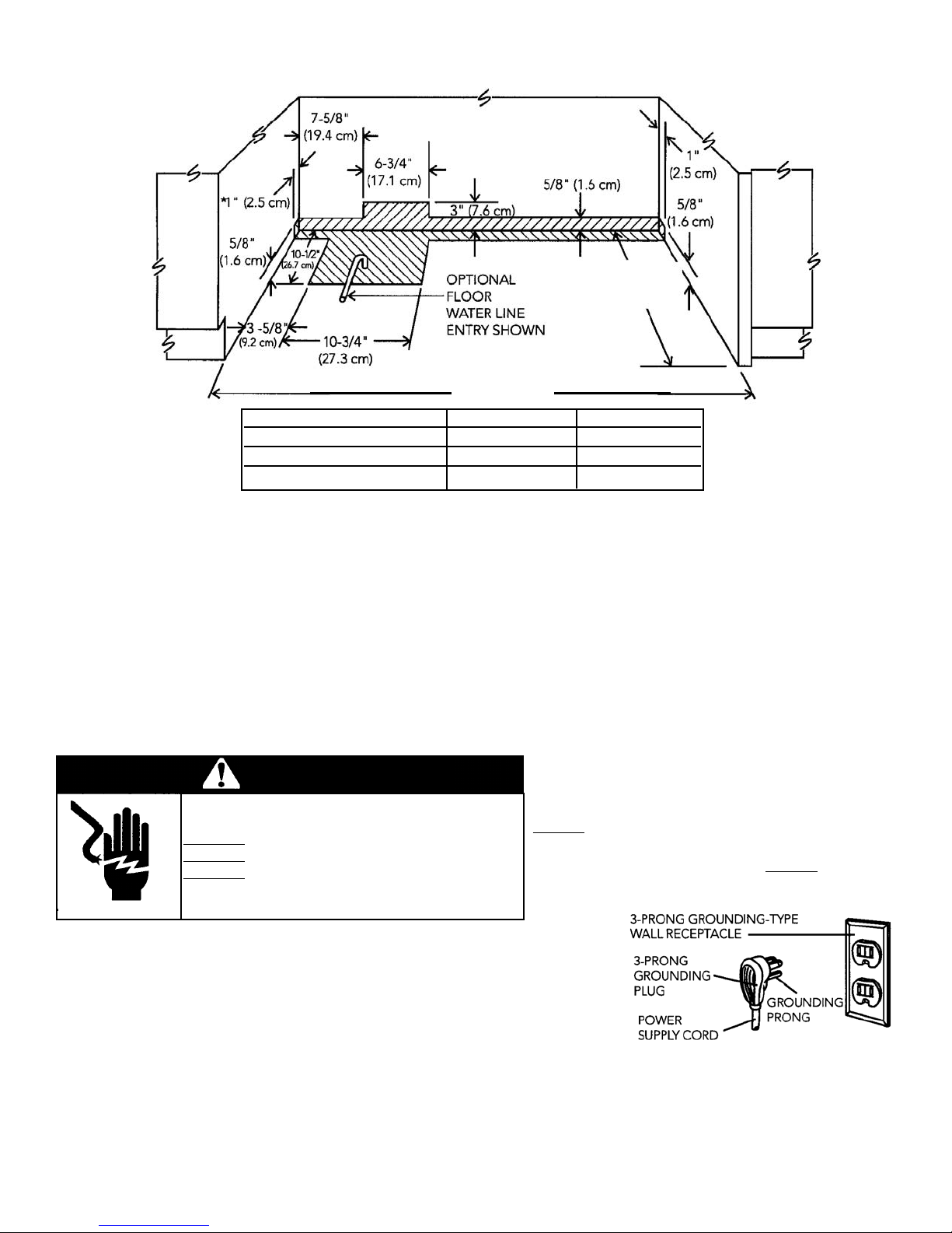
Plumbing Dimensions
AA BB
36” W. Professional 35 1/2” (90.2 cm) 24” (61.0 cm)
36” W. Designer 36” (91.5 cm) 24” (61.0 cm)
36” W. Full Overlay 36” (91.5 cm) 25” (63.5 cm)
BB
AA
**NNoottee:: MMuusstt bbee
uunnddeerr 11”” ((22..55 ccmm))
ffrroomm bbaacckk wwaallll
AREA REQUIREMENTS
VVeerriiffyy tthhee ffoolllloowwiinngg::
•Unit can fit into residence and can be moved around corners and through doorways.
•Floors can support unit’s weight plus food weight (approximately 1200 pounds [540 kg] total).
•Rear wall is solid and is able to support two (2) horizontally mounted 2X4s (included) bolted to 2 wall studs. The 2X4
board bolt heads must be flush with 2X4 to prevent obstruction.
•Remove anything attached to rear or side walls that can obstruct unit installation.
•Cutout dimensions are accurate.
•Electrical outlet is in correct location.
•Water line is in correct location.
ELECTRICAL REQUIREMENTS
IItt iiss tthhee ccuussttoommeerr’’ss rreessppoonnssiibbiilliittyy ttoo::
•contact a qualified electrical installer.
•assure that the electrical installation is adequate and in conformance with the
National Electrical Code, ANSI/NFPA 70-latest edition or Canadian Electrical
Code C22.1-1998 and C22.2 No. 0-M91 (or latest edition), and all local codes
and ordinances. (115 volt, 60-Hz, 15 amp, fused, electrical supply is required.
It is required that a separate circuit serving only this appliance be provided.
This appliance is equipped with a power supply cord having a 3-prong grounding plug. To minimize possible shock
hazard, the cord must be plugged into a mating 3-prong, grounding-type wall receptacle. Do not use an extension
cord.)
IIff ccooddeess ppeerrmmiitt aa sseeppaarraattee ggrroouunnddiinngg wwiirree ttoo bbee
uusseedd,, iitt iiss rreeccoommmmeennddeedd tthhaatt aa qquuaalliiffiieedd eelleeccttrriicciiaan
n
ddeetteerrmmiinnee tthhaatt tthhee ggrroouunnddiinngg ppaatthh iiss aaddeeqquuaattee..
DDoo NNoott
ggrroouunndd ttoo aa ggaass ppiippee.. CChheecckk wwiitthh aa
qquuaalliiffiieedd eelleeccttrriicciiaann iiff yyoouu aarree nnoott ssuurree tthhee
aapppplliiaannccee iiss pprrooppeer
rllyy ggrroouunnddeedd.. DDoo NNoott hhaavvee aa
ffuussee iinn tthhee nneeuuttrraall oorr ggrroouunnddiinngg cciirrccuuiitt..
EELLEECCTTRRIICCAALL SSHHOOCCKK HHAAZZAARRDD
PPlluugg iinnttoo aa ggrroouunnddeedd 33--pprroonngg oouuttlleett..
DDOO NNOOTT rreemmoovvee ggrroouunndd pplluugg..
DDOO NNOOTT uussee aann aaddaapptteerr..
DDOO NNOOTT
uussee aann eexxtteennssiioonn ccoorrdd..
FFaaiilluurree ttoo ffoollllooww tthheessee iinnssttrruuccttiioonnss ccoouulldd rreessuulltt iinn
ffiirree oorr eelleeccttrriiccaall sshhoocckk.
.
WARNING
Page 9
9
Anti-Tip Requirements
The anti-tip boards should be fastened
into position prior to moving the unit into
the opening.
Note: Additional mounting boards may
be required if the unit does not touch
the back wall of the enclosure. To
prevent unit from tipping forward, it
must be secured in place with a solid
soffit or wood block.
TTIIPP OOVVEERR HHAAZZAARRDD
AApppplliiaannccee iiss ttoopp hheeaavvyy aanndd ttiippss eeaassiillyy wwhheenn nnoott
ccoommpplleetteellyy iinnssttaalllleedd..
KKeeeepp ddoooorrss ccllo
osseedd uunnttiill aapppplliiaannccee iiss ccoommpplleetteellyy
iinnssttaalllleedd aanndd sseeccuurreedd ppeerr iinnssttaallllaattiioonn iinnssttrruuccttiioonnss..
UUssee ttwwoo oorr m
moorree ppeeooppllee ttoo mmoovvee aanndd iinnssttaallll
aapppplliiaannccee.. FFaaiilluurree ttoo ddoo ssoo ccaann rreessuulltt iinn ddeeaatthh oorr
sseerriioouuss iinnjjuurryy..
WARNING
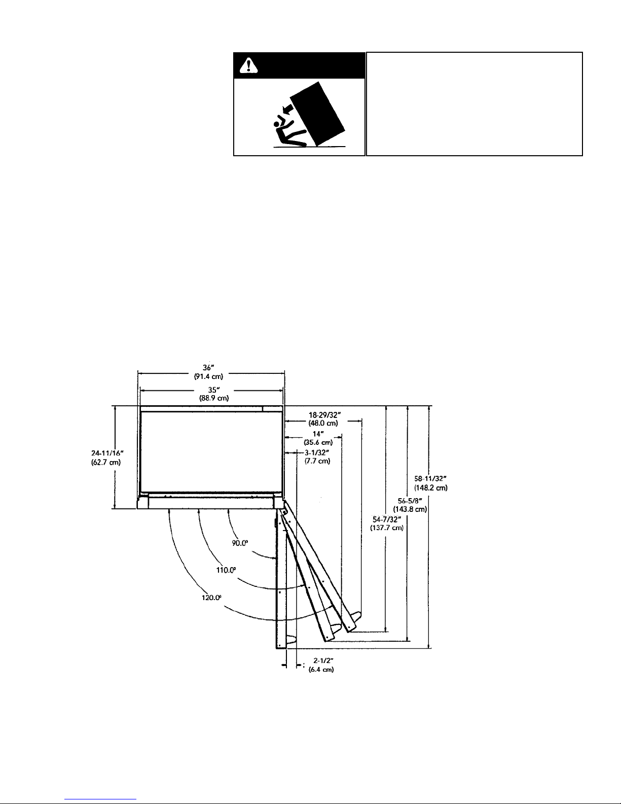
DOOR SWING CONSIDERATIONS
PROFESSIONAL MODEL
Page 10
10
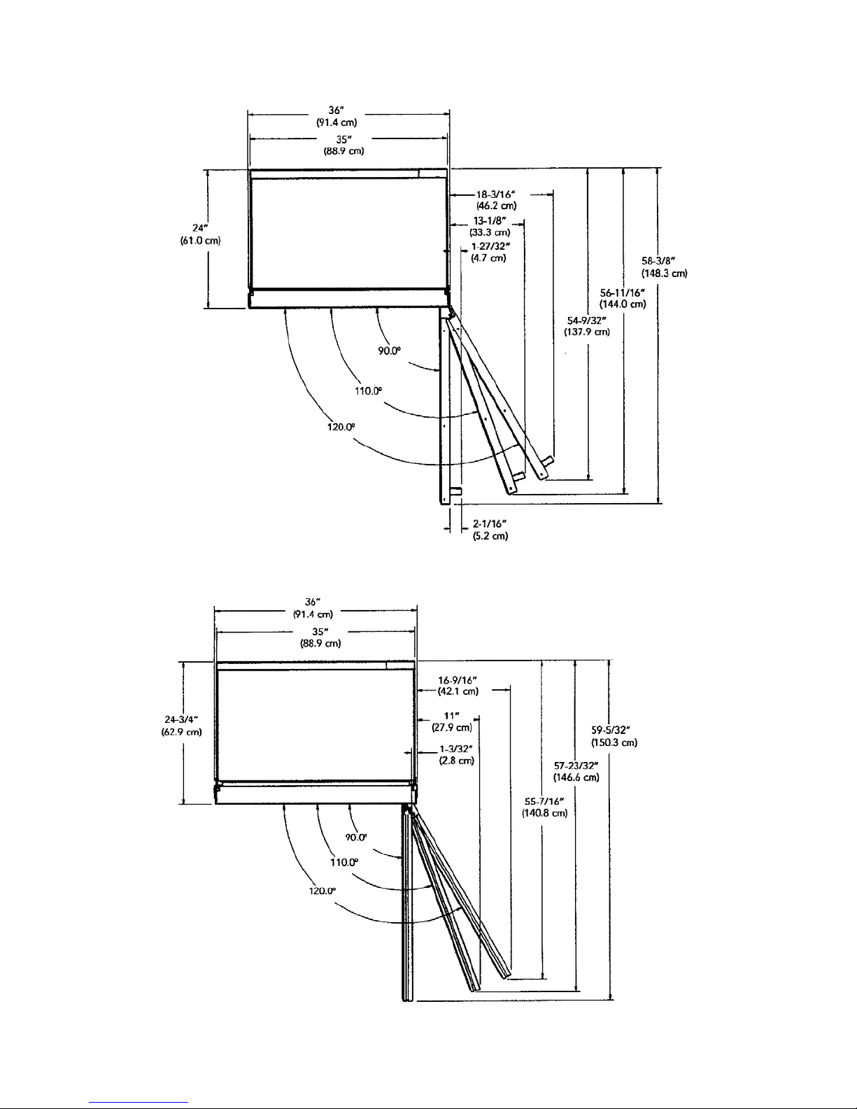
DOOR SWING CONSIDERATIONS
DESIGNER MODEL
FULL OVERLAY MODEL
Page 11

11
TIPPING CONSIDERATIONS
PROFESSIONAL MODELS
DESIGNER AND FULL OVERLAY MODELS
82-5/8”
(209.9 cm)
86-1/16”
(218.6 cm)
Page 12
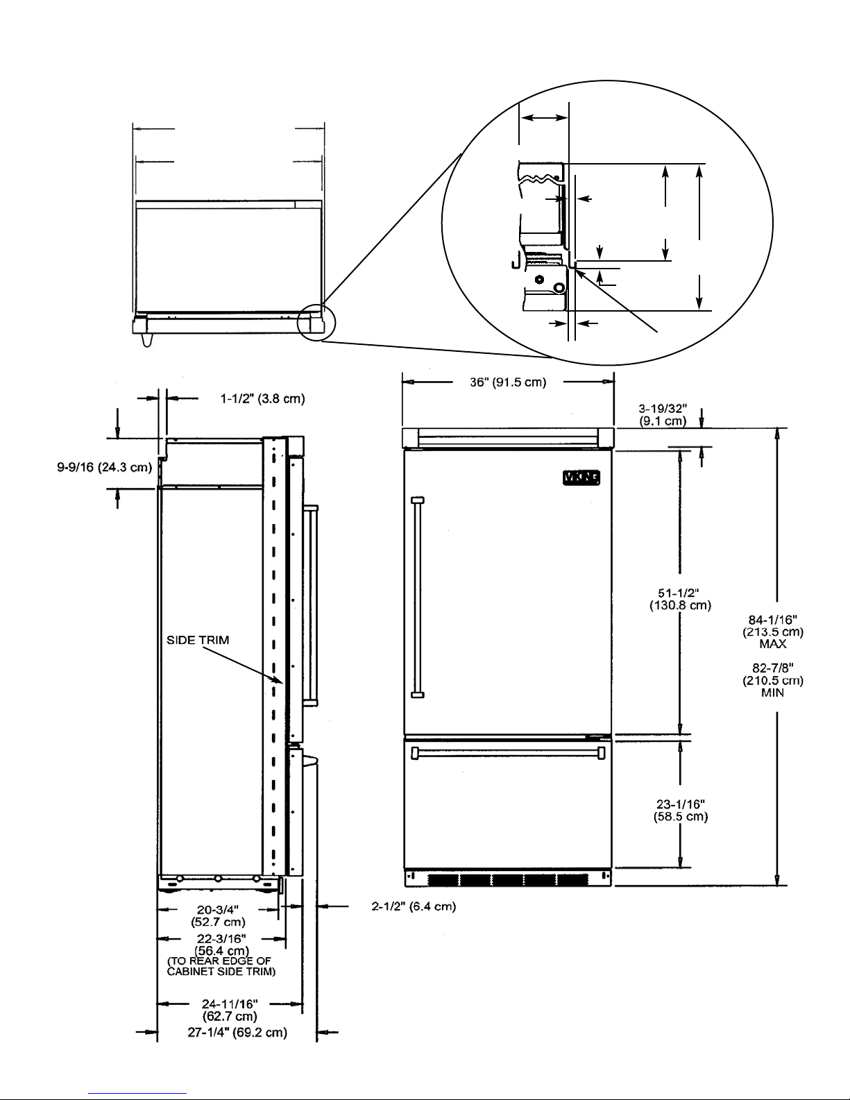
BOTTOM MOUNT REFRIGERATOR OVERALL DIMENSIONS
PROFESSIONAL MODEL
SS
SS
SS
35-1/2”
(90.2 cm)
22 3/16”
(56.4 cm)
24 3/4”
(62.9 cm)
5/16”
(0.8 cm)
9/32”
(0.7 cm)
11/32”
(0.9 cm)
DDOOOORR
Side Trim
TTOOPP
35-1/2” (90.2 cm)
35” (88.9 cm)
SSIIDDEE
FFRROONNTT
12
Page 13
13
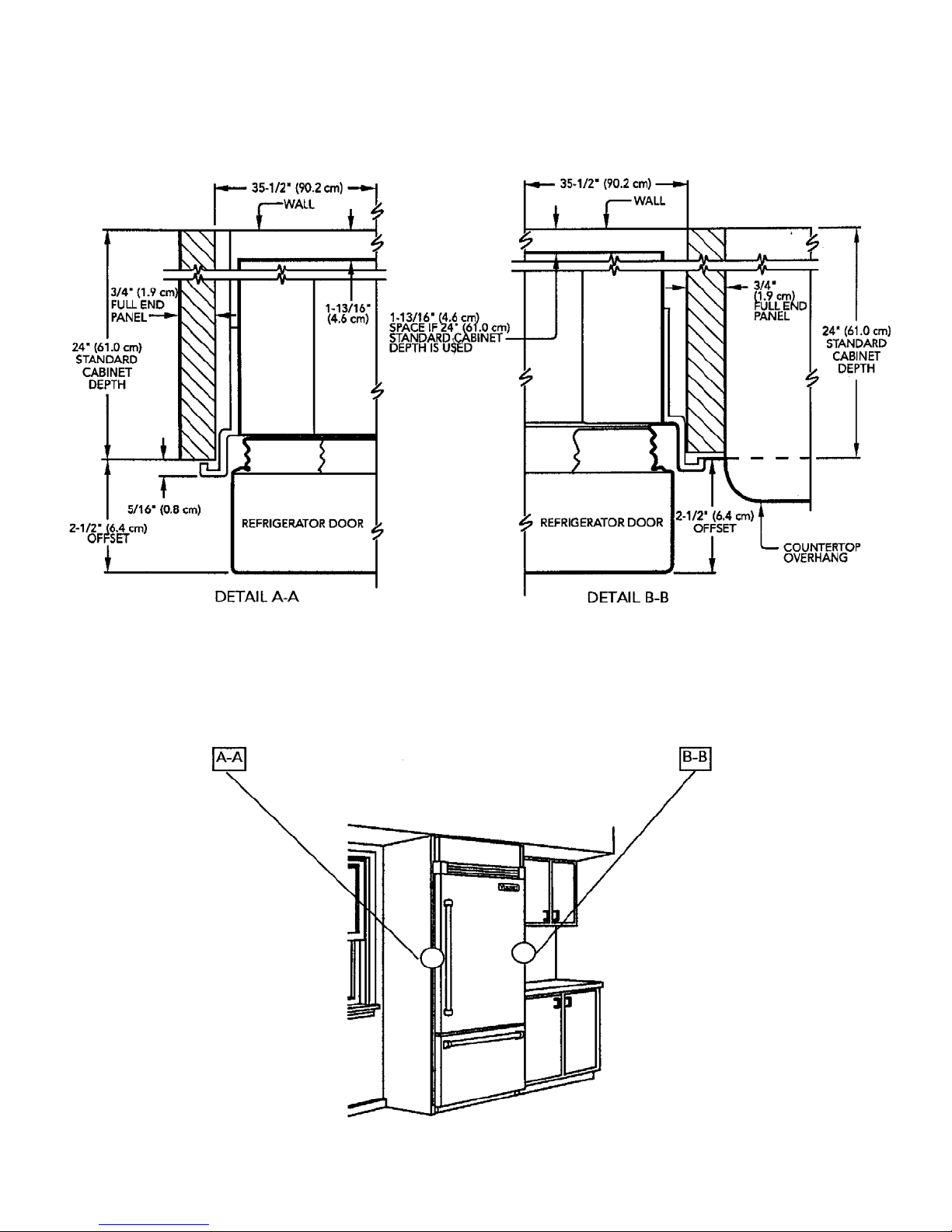
CABINET INFORMATION - PROFESSIONAL MODELS
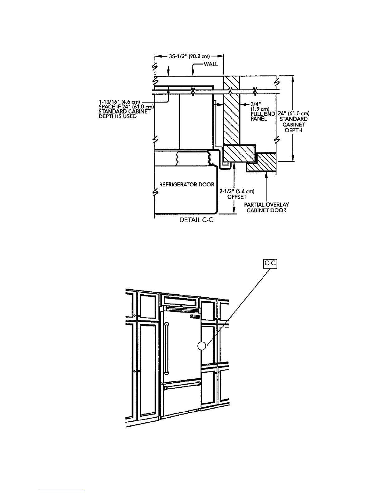
Professional models fit “semi-flush” in standard 24” (61.0 cm) deep cabinet openings. The door face protrudes 2-1/2”
(6.4 cm) from the cabinet face. The handle protrudes an additional 2-1/2” (6.4 cm) into the room
Page 14
14
CABINET INFORMATION - PROFESSIONAL MODELS (Cont’d)
Page 15
15
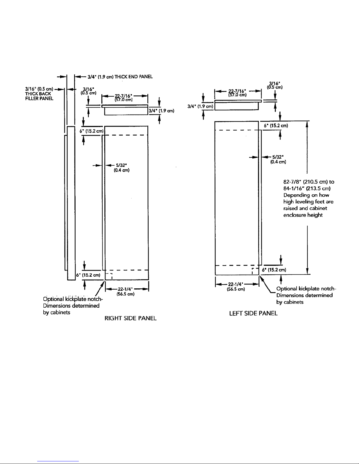
CUSTOM SIDE PANEL DIMENSIONS - PROFESSIONAL MODELS
FOR 3/4" (1.9 cm) SIDE PANELS
Page 16
16
BOTTOM MOUNT REFRIGERATOR OVERALL DIMENSIONS
DESIGNER MODELS
TTOOPP
SSIIDDEE
36” (91.5 cm)
DDOOOORR
FFRROONNTT
36” (91.5 cm)
35” (88.9 cm)
Page 17
17
CABINET AND PANEL INFORMATION - DESIGNER MODELS
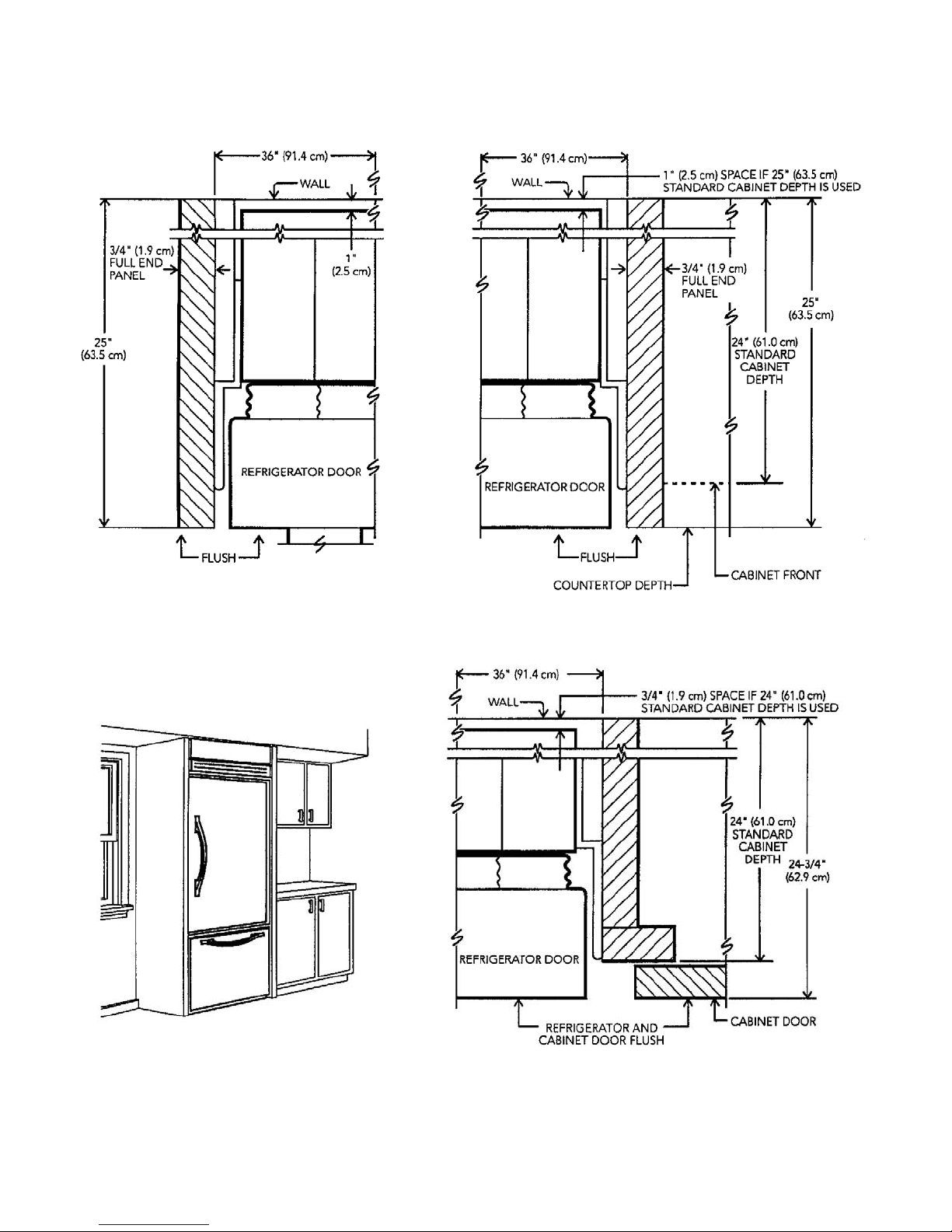
Designer models fit flush in standard 24” (61.0 cm) deep cabinet openings with no protrusion into the room except 2”
(5.1 cm) curved handle depth
Page 18
18
CABINET AND PANEL INFORMATION - FULL OVERLAY MODELS
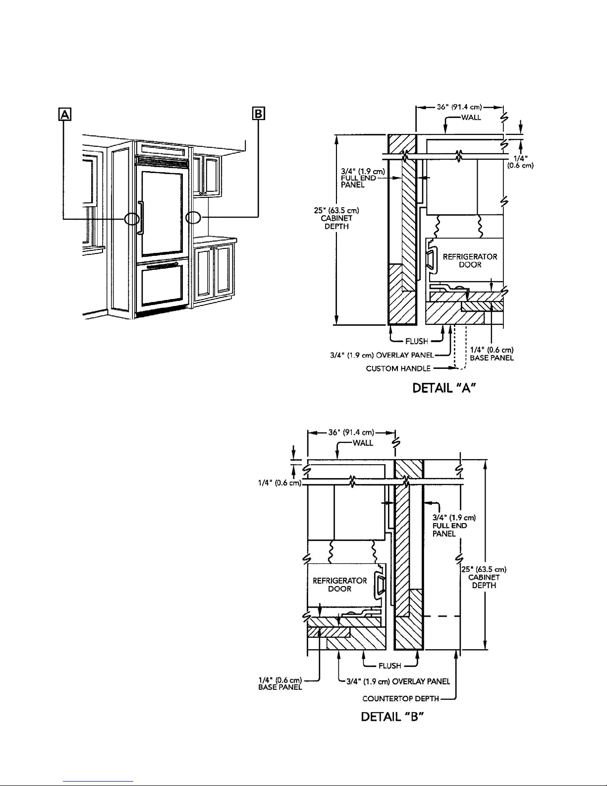
Full overlay models, (with 3/4” [1.9 cm], thick panels and custom handles locally supplied), fit flush in 25” (63.5 cm) deep (countertop
depth) cabinet openings with no protrusion into room except custom handles
TTOOPP
36” (91.5 cm)
36” (91.5 cm)
35” (88.9 cm)
Page 19
19
CABINET AND PANEL INFORMATION - FULL OVERLAY MODELS
Full overlay models, (with 3/4” [1.9 cm], thick panels and custom handles locally supplied), fit flush in 25” (63.5 cm) deep (countertop
depth) cabinet openings with no protrusion into room except custom handles
Page 20
20
CABINET AND PANEL INFORMATION - FULL OVERLAY MODELS (Cont’d)
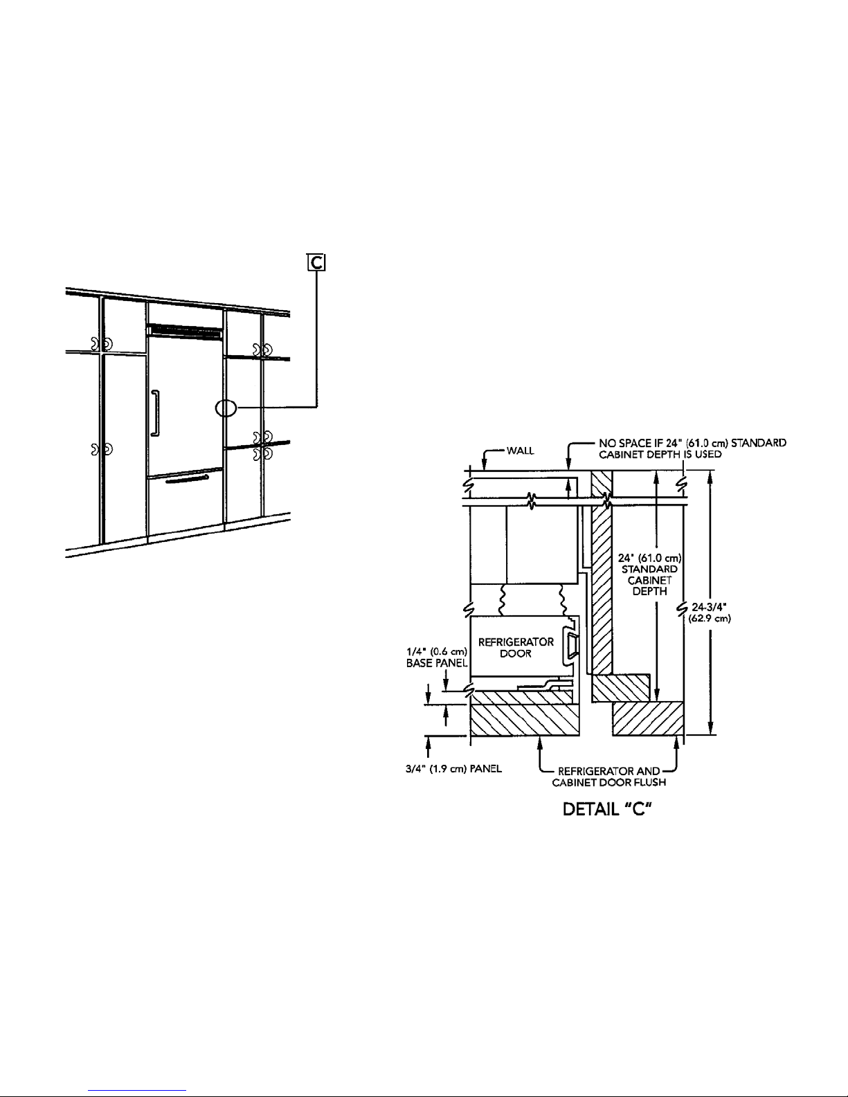
Full overlay models can be installed in standard 24” (61.0 cm) deep openings. However, the door faces and top ventilation grille
will protrude 3/4” (1.9 cm) into the room. This is ideal for alignment with full overlay cabinet doors.
Page 21
21
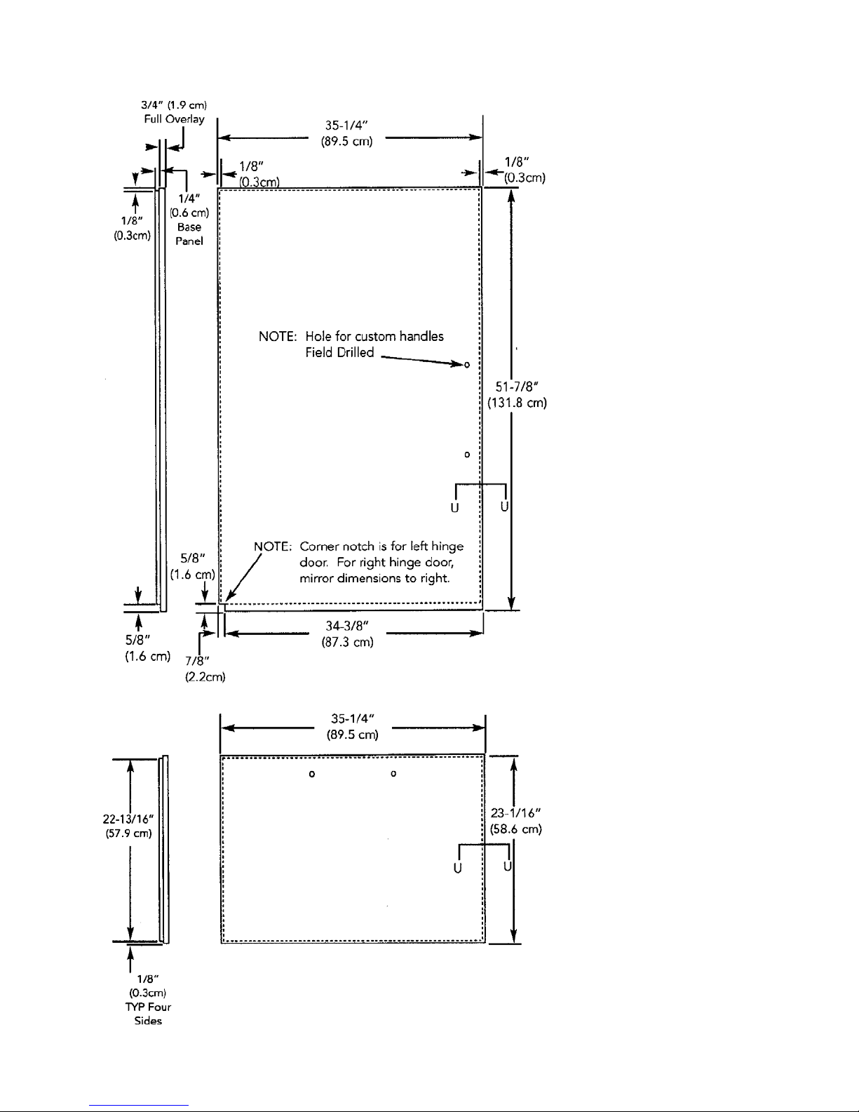
CUSTOM PANEL DIMENSIONS
Page 22
22
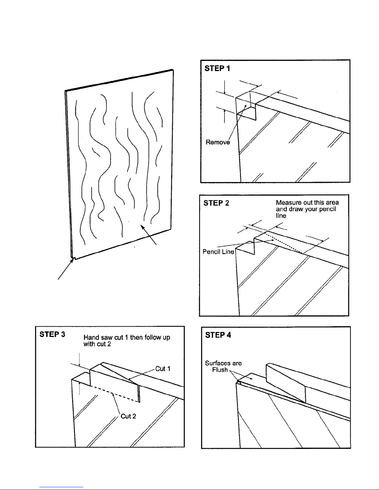
CUSTOM PANEL HINGE CUTOUT DETAIL
NOTE: Steps below show panel upside down and notched for a left hinge application. Overview of door and notch
location can be seen in Figure A.
For a right hinge door, mirror
dimensions to the right
Notch for left hinge
door
Figure A
Front side of 3/4”
(1.9 cm) panel
7/8”
(2.2 cm)
5/8”
(1.6 cm)
BBaacckkssiiddee ooff
33//44”” ((11..99 ccmm)) ppaanneell wwiitthhoouutt tthhee
11//44”” ((00..66 ccmm))
bbaassee ppaanneell
1/8”
(0.3 cm)
2” (5.1 cm)
FFiinnaall vviieeww sshhoowwnn wwiitthh 11//44”” ((00..66 ccmm))
bbaassee ppaanneell aaddddeedd
5/8” (1.6 cm)
Page 23

23
DOOR PANEL INSTALLATION
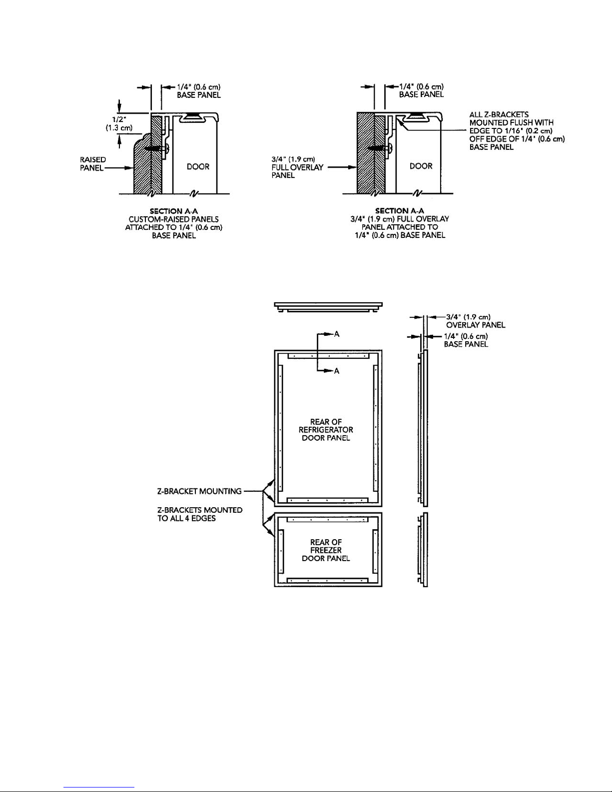
Panels must not weigh more than 50 pounds per door. Refer to “Custom Panel Dimensions” on page 21 for detailed
panel instructions.
Refrigerator Door
1. Remove cabinet side trim with a phillips screwdriver.
2. Remove handle-side door trim with a phillips screwdriver.
3. Install “Z” brackets (see page 24 for details).
4. Align panel in door trim and push evenly. For smoother installation, apply liquid soap to door trim and “Z”
brackets.
5. Install handle-side door trim with screws. Install door trim inserts (supplied) on all four sides of door by starting in
one corner and pushing the strip in place.
6. Install cabinet side trim
Freezer Door
1. Remove handle-side door trim with a phillips screwdriver.
2. Install “Z” brackets (see page 24 for details).
3. Align panel in door trim and push evenly. For smoother installation, apply liquid soap to door trim and “Z” brackets.
4. Install handle-side door trim with screws. Install door trim inserts (supplied) on all four sides of door by starting in
one corner and pushing the strip in place.
Page 24
24
“Z” BRACKET INSTALLATION
Page 25
25
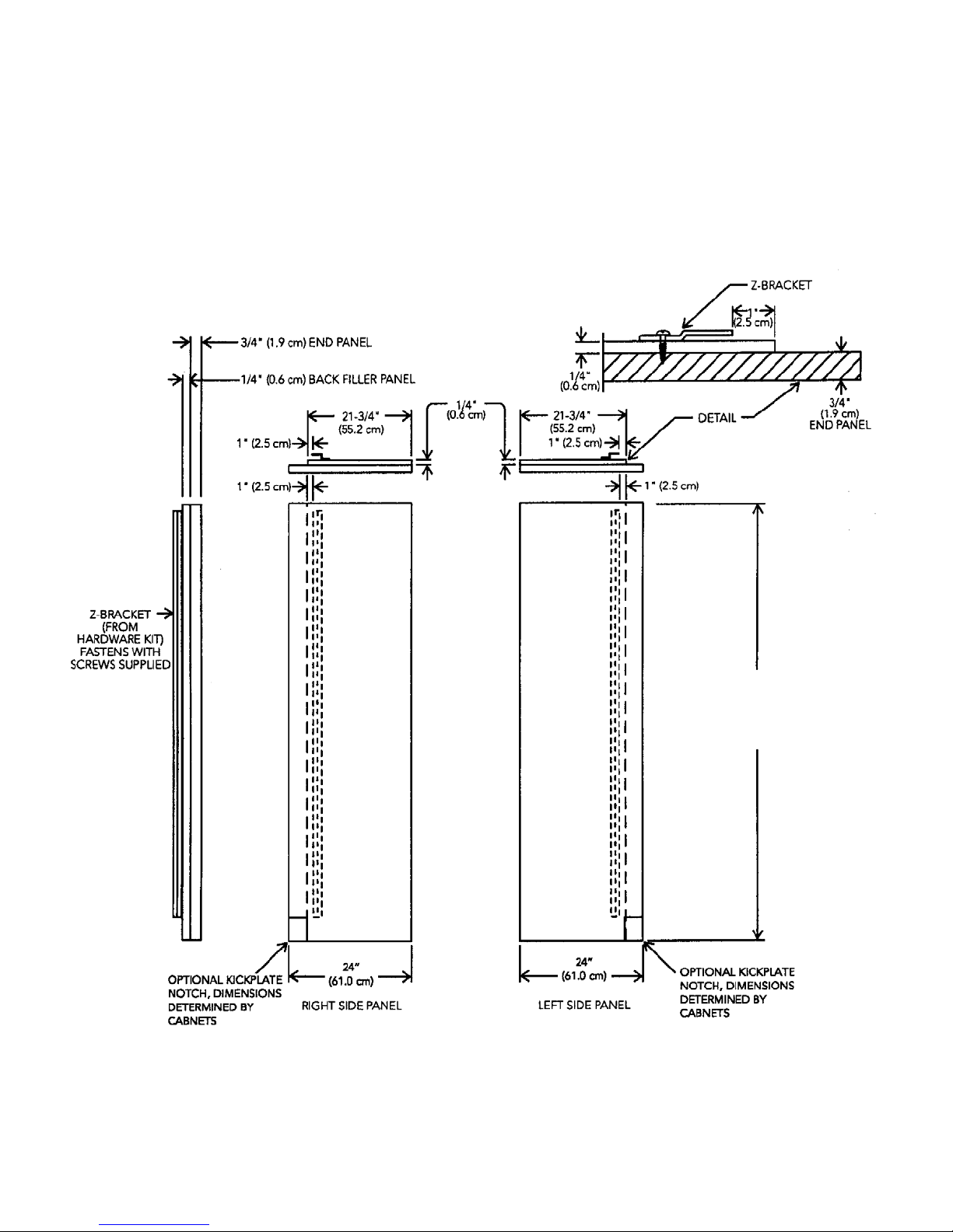
CUSTOM SIDE PANEL DIMENSIONS
DESIGNER/FULL OVERLAY MODELS
FFOORR 33//44”” ((11..99 ccmm)) SSIIDDEE PPAANNEELLSS
NNOOTTEE:: AAddddiinngg aa 33//44”” ((11..99 ccmm)) ssiiddee ppaanneell aaddddss aann aaddddiittiioonnaall 33//44”” ((11..99
ccmm)) ttoo tthhee oovveerraallll wwiiddtthh ooff tthhee pprroodduucctt ffoorr eeaacchh
ssiiddee ppaanneell uusseedd..
NNOOTTEE:: RReeqquuiirreess ssiiddee ppaanneell hhaarrddwwaar
ree kkiitt ((KKiitt MMooddeell NNuummbbeerr -- SSPPHHKKDDSS))
8822--77//88”” ((221100..55 ccmm)) ttoo 8844--11//1166”” (( 221133..55 ccmm))
DDEEPPEENNDDIINNGG OONN HHOOWW HHIIGGHH LLEEVVEELLIINNGG
FFEEEETT AARREE RRAAIISSEEDD,, AANNDD CCAABBIIN
NEETT
EENNCCLLOOSSUURREE HHEEIIGGHHTT
Page 26
26
CUSTOM FINISHING OPTIONS
Door Clearances
All installations must allow for the refrigerator and freezer door to open a minimum of 90o.
•For side wall or corner installation, allow for a standard 3” (7.6 cm) cabinet filler to assure doors open to 90
o
. If a
custom handle is used a wider filler may be necessary.
•Panel thickness must not exceed 1” (2.5 cm) on hinge side. Thicker panels will interfere with door swing and
clearance.
•Panels must not exceed 50 pounds per door.
Door Panel Requirements
Verify panel sizes, handle clearances, and placement before beginning installation. See “Custom Panel Dimensions” on
page 21.
•In some instances, raised panels may require a handle recess (see page 10).
•Panels thicker than 1” (2.5 cm) require special consideration with door swings and clearances (see page 9-10).
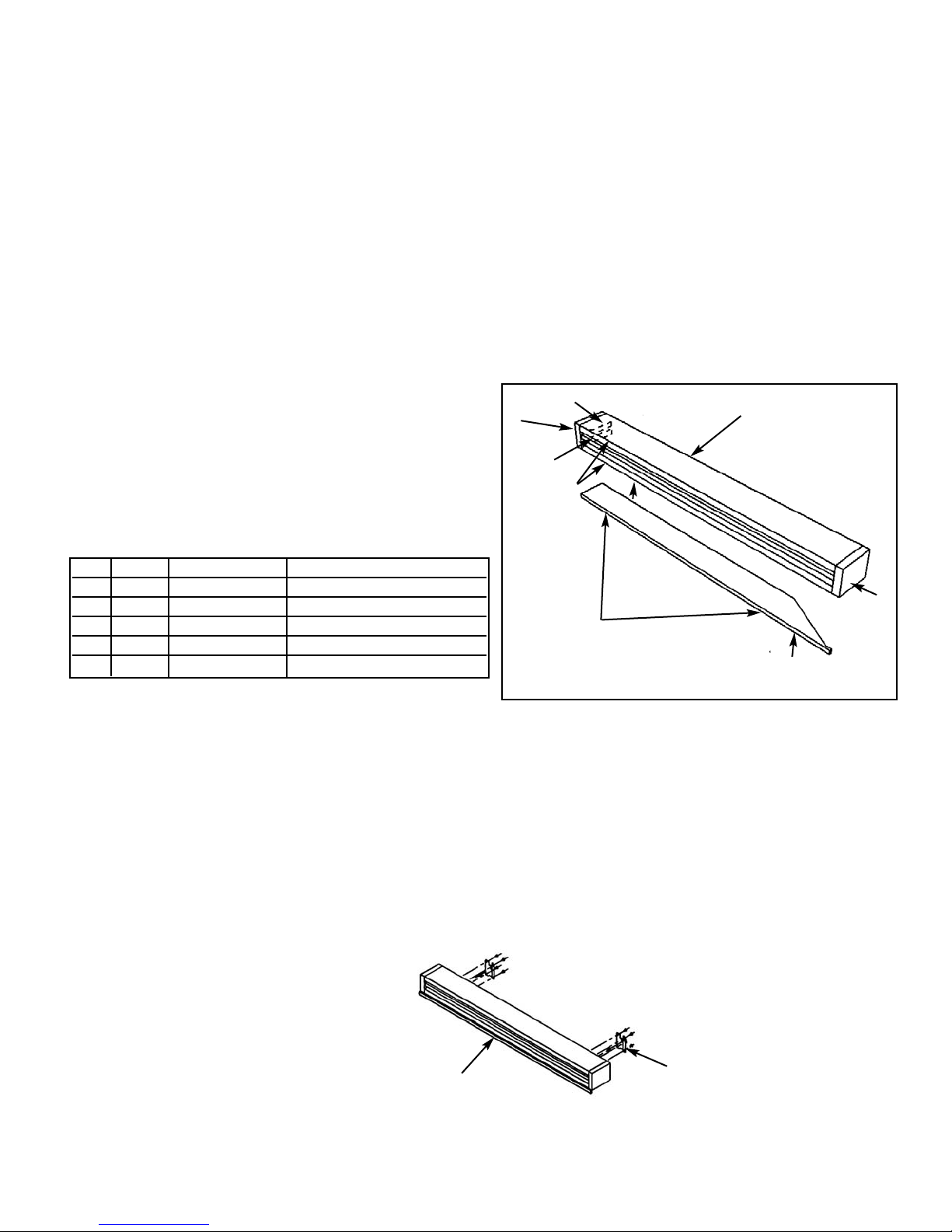
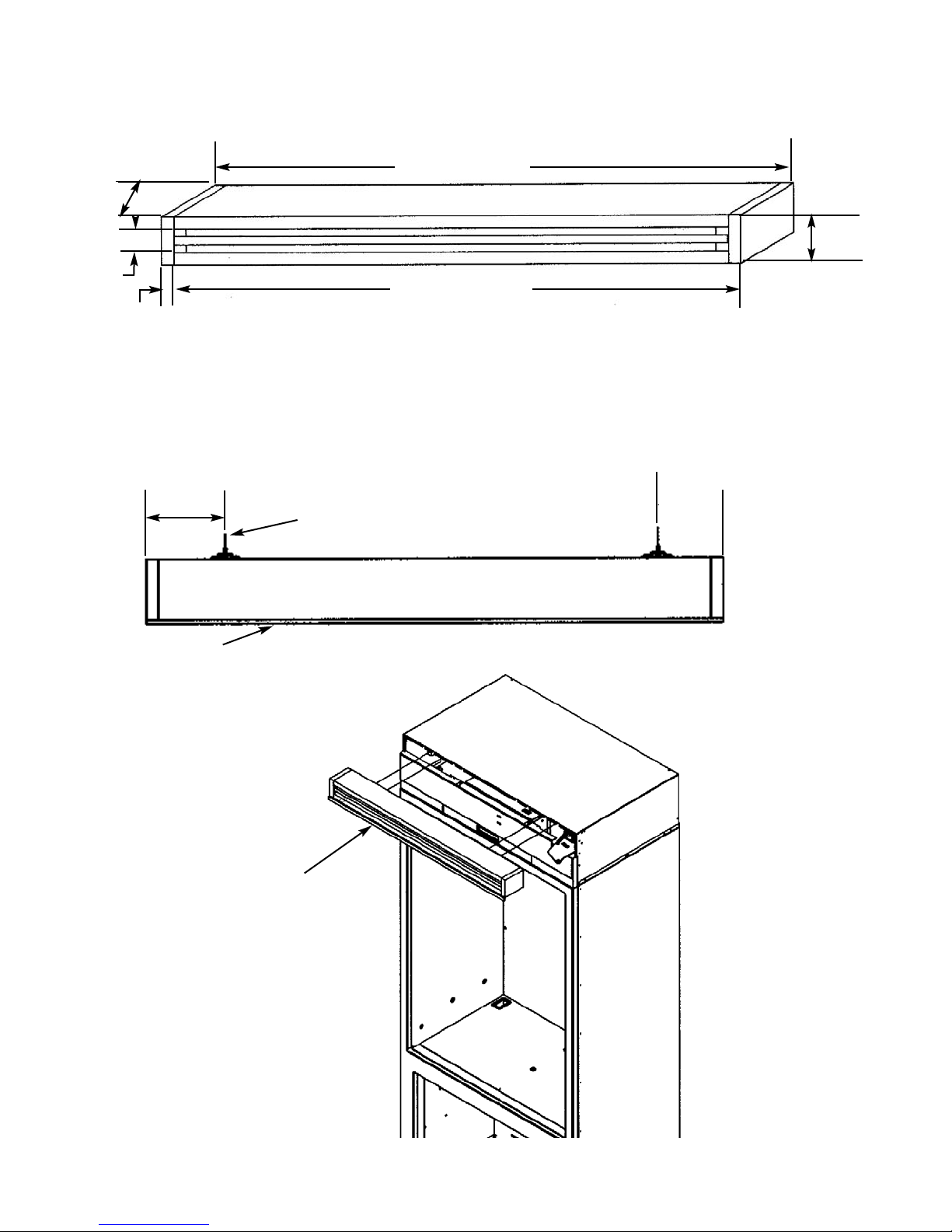
Custom Air Grille Panel (Optional)
A louvered aluminum air grille is supplied with the
refrigerator. For custom wood grille application see
template in “Custom Air Grille Panel Dimensions” on pages
31-32.
Right hinge application:
Item Qty Description Size
A 2 End 3”x 3-3/4” x 3/4”
B 2 Top & Bottom See page 28
C 2 Insert End 1-1/2” x 2-3/4” x 3/4”
D 1 Hinge Cover See page 29
E 1 Insert See page 29
IInnssttaallll wwoooodd ggrriillllee bbyy ccoommpplleettiinngg tthhee ffoolllloowwiinngg::
1. Remove air grille center blade.
2. Remove (2) 1/4” (.6 cm) screws with a magnetic extended screwdriver at least 8” (20.3 cm) long.
3. Pull air grille assembly forward.
4. Remove (2) mounting brackets from the air grille assembly.
5. Using (8) screws removed from the mounting brackets, attach mounting brackets to the custom wood grille using
predrilled pilot holes. (See page 27 for proper alignment of custom air grille to mounting brackets and pilot hole
placement.)
6. Replace air grille assembly by reversing Step 2.
C
A
E
B
A
D
Optional 1/2” (1.3 cm) hinge cover
is fastened to bottom of wood
grille. (Hinge cover will protrude
9/32” [0.7 cm] from wood grille.)
Wood grille is made
of 3” (7.6 cm) filler
stock.
Screws
BracketCustom air grille front
Page 27
27
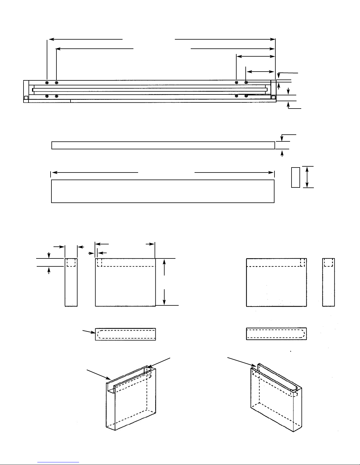
OPTIONAL CUSTOM AIR GRILLE DIMENSIONS
OPTIONAL CUSTOM AIR GRILLE DUCT LIP EDGE LOCATIONS
FFRROONNTT VVIIEEWW
35-1/2” (90.2 cm)
34” (86.4 cm)
3/4” (1.9 cm) TYP
1 1/2”
(3.8 cm)
3”
(7.6 cm)
3 3/4”
(9.5 cm)
TOP OF CUSTOM AIR GRILLE
Bracket
Custom Air Grille
4 7/8”
(12.3 cm)
4”
(10.2 cm)
Front of Air Grille
Page 28
28
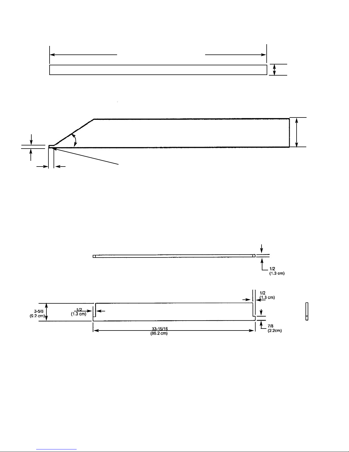
REAR VIEW DIMENSIONS
TOP AND BOTTOM VIEW DIMENSIONS
ENDS DIMENSIONS
32-3/16” (81.8 cm)
34” (86.4 cm)
30-27/32” (78.3 cm)
5-17/32”
(14.0 cm)
4-11/64”
(10.6 cm)
3/8” (0.95 cm)
1/2” (1.3 cm)
3/4” (1.9 cm)
3 3/4”
(9.5 cm)
TOP VIEW
RIGHT VIEW
LEFT FRONT VIEW
1/2”
(1.3 cm)
3/4”(1.9 cm)
3 3/4”(9.5 cm)
1/8”(0.3 cm)
3”
(7.6 cm)
Bottom View
R1/4”
Route a 1/2” (1.3cm) wide by 1/2” (1.3 cm) deep slot
centered in bottom of end panel over hinge point.
Bottom of end panel
RIGHT FRONT VIEW
(dimensions mirrored from left front view)
BOTTOM VIEW
Page 29
29
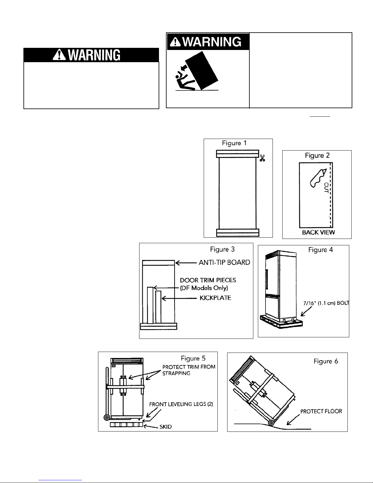
HINGE COVER DIMENSIONS
1/2” (1.3 cm)
3-1/8”
(7.9 cm)
1/4” (0.6 cm)
26
o
23/32”
(1.8 cm)
Hinge cover protrudes 9/32” (0.7 cm) beyond wood grille
35-1/2 (90.2 cm)
INSERT DIMENSIONS
TOP VIEW
FRONT VIEW
Right View
Page 30
30
MMoosstt ooff tthhee uunniitt’’ss wweeiigghhtt iiss aatt tthhee ttoopp.. EExxttrraa ccaarree iiss nneeeeddeedd wwhheenn mmoovviinngg tthhee uunniitt ttoo pprreevveenntt ttiippppiinngg.. DDoo NNoott
rreemmoovvee pprrootteeccttiivvee ffiillmm uunnttiill uunniitt iiss iinn ooppeerraattiinngg ppoossiittiioonn.. AAllll ffoouurr lleevveelliinngg lleeggss mmuusstt ccoonnttaacctt tthhee fflloooorr ttoo ssuuppppoorrtt aanndd
ssttaabbiilliizzee tthhee ffuullll wweeiigghhtt.. DDoo nnoott ddrroopp uunniitt..
1. Remove exterior shipping materials prior to moving unit into
home. Remove top and bottom strap (see Figure 1).
2. Remove top cap (see Figure 1).
3. Cut carton rear approximately 1/4” (0.6 cm) to 1” (2.5 cm)
from right corner (see Figure 2) with a utility knife extended
1/4” (0.6 cm). Remove carton and exterior packaging. Save
cardboard shipping material to protect floor surface when
installing unit. Do not remove nylon cord from power cord.
Remove anti-tip board, kickplate and door trim pieces (DF
models) from rear of unit
(see Figure 3).
4. Remove shipping brackets from skid
by removing 4 bolts (2 each side) with
a 1/2” socket head screwdriver (see
Figure 4).
•Tilting unit is not required to remove
shipping brackets.
5. Slip cart between unit and skid.
Remove unit from skid. Use excess
packaging to protect decorative trim.
Verify that leveling legs are up (0”
adjustment) (see
Figure 5).
6. To avoid floor damage,
use protective material
(see Figure 6).
UUssee ttwwoo oorr mmoorree ppeeooppllee ttoo mmoovvee aanndd iinnssttaallll
uunniitt.. FFaaiilluurree ttoo ffoollllooww tthhiiss iinnssttrruuccttiioonn ccaann rreessuulltt
iinn b
baacckk oorr ootthheerr iinnjjuurryy.. TToo aavvooiidd ppeerrssoonnaall iinnjjuurryy,,
wweeaarr gglloovveess wwhheenn ppeerrffoorrmmiinngg aannyy iinnssttaallllaattiioonn
pprroocceeddu
urree aanndd wweeaarr eeyyee pprrootteeccttiioonn wwhheenn
ccuuttttiinngg mmeettaall ssttrraappss..
TTIIPP OOVVEERR HHAAZZAARRDD
AApppplliiaannccee iiss ttoopp hheeaavvyy aanndd ttiippss eeaassiillyy
wwhheenn nnoott ccoommpplleetteellyy iinnssttaalllleedd.. KKeeeepp
ddoooorrss ccllo
osseedd uunnttiill aapppplliiaannccee iiss
ccoommpplleetteellyy iinnssttaalllleedd aanndd sseeccuurreedd ppeerr
iinnssttaallllaattiioonn iinnssttrruuccttiioonnss.. UUssee ttwwoo oorr
m
moorree ppeeooppllee ttoo mmoovvee aanndd iinnssttaallll
aapppplliiaannccee.. FFaaiilluurree ttoo ddoo ssoo ccaann rreessuulltt
iinn ddeeaatthh oorr sseerriioouuss iinnjjuurryy..
UNIT INSTALLATION
Page 31
31
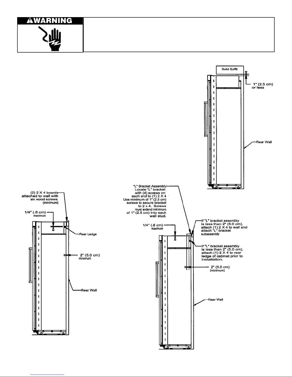
SECURING THE UNIT (3 OPTIONS)
OPTION 1
If a solid soffit is 1” (2.5 cm) or less above the unit, anti-tip boards are not required.
OPTION 2
If a solid soffit is not available or soffit is more than 1” (2.5 cm) above unit, center
wood boards on rear wall 1/4” (.6 cm) maximum above unit. Attach wood boards to
wall studs with six of the provided wood screws, making sure that screws are engaged
in wall studs 1 1/2” (3.8 cm) minimum.
OPTION 3
Create “L” bracket assembly by securing “L” brackets to each end of (1) 2x4 with
provided screws (Item A). If 2x4 does not extend 2” (5.0 cm) beyond rear ledge,
attach (1) 2x4 to wall (Item B), attach (1) 2x4 to rear ledge of cabinet (Item C) and
attach “L” bracket assembly to 2x4 mounted on wall (Item A).
EElleeccttrriiccaall SShhoocckk HHaazzaarrdd
DDiissccoonnnneecctt ppoowweerr aatt bbrreeaakkeerr oorr ttuurrnn ppoowweerr ddiissccoonnnneecctt sswwiittcchh ttoo OOFFFF ppoossiittiioonn
bbeeffoorree
ppeerrffoorrmmiinngg aannyy iinnssttaallllaattiioonn pprroocceedduurree.. FFaaiilluurree ttoo ddoo ssoo ccaann rreessuulltt iinn ddeeaatthh oorr eelleeccttrriiccaall
ssh
hoocckk..
(ITEM B)
OPTION 2
OPTION 3
(ITEM A)
(ITEM C)
OPTION 1
Page 32
32
UNIT INSTALLATION (Cont’d)
Before moving the unit in place, confirm the finished dimensions, electrical location, minimum door and shelf
clearances, and door panel instructions.
1. Position unit in front of cutout.
2. Remove the top air grille assembly.
a. Remove the center grille louver by lifting up and pulling forward.
b. Remove the grille/end cap assembly by removing two (2) screws.
3. Verify operation by plugging power cord in receptacle.
PPoowweerr sswwiittcchh wwiillll bbee sshhiippppeedd iinn tthhee ““OONN”” ppoossiittiioonn aanndd
sshhoowwrroooomm sswwiittcchh wwiillll bbee iinn tthhee ““OONN”” ppoossi
ittiioonn..
(If showroom switch is switched to the “OFF” position, showroom
mode is engaged and power is shut-off to the compressor. This mode is for showroom display only).
PPoowweerr
SSwwiittcchh
SShhoowwrroooomm
SSwwiittcchh
4. Roll unit into cutout to within 3” (7.6 cm) of being flush with cabinets. To avoid kitchen cabinet damage, place
cardboard between cabinets and unit. Push cardboard back with unit and remove cardboard when unit are in place.
Remove power cord slack by pulling nylon cord straight out while pushing unit completely into place. Power and
nylon cord will rest along unit side.
NNOOTTEE:: WWhheenn mmoovviinngg tthhee uunniitt iinnttoo ppoossiittiioonn,, bbee ccaarreeffuull nnoott ttoo ccrriimmpp,, kkiinnkk oorr
ccrruusshh tthhee ccooppppeerr wwaatteer
r ssuuppppllyy lliinnee..
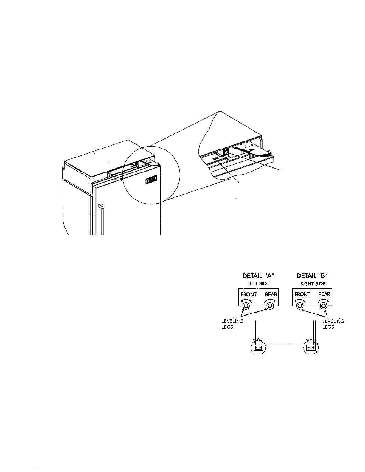
5. Lift the unit off the rollers, adjust to desired height and level unit
by using a 5/16” hex head wrench. (Refer to Figure at the right)
a) To raise (clockwise)/lower (counterclockwise) right side
rear, rotate the right side rear hex rod.
b) To raise (clockwise)/lower (counterclockwise) the left side
rear, rotate the left side rear hex rod.
c) To raise (clockwise)/lower (counterclockwise) the right
side front, rotate the right side front hex rod.
d) To raise (clockwise)/lower (counterclockwise) the left side
front, rotate the left side front hex rod.
NNOOTTEE:: DDOO NNOOTT uussee aann eelleeccttrriicc ddrriivviinngg ddeevviiccee.. OOvveerrttiigghhtteenniinngg ccaann
ccaauussee ddaamma
aggee..
6. To secure unit, raise unit until compartment cover is firmly seated under the soffit or anti-tip boards. Refer to
“Securing the Unit” section on page 31 for more information.
7. Open door. Display should flash. Press Display On pad. There is a 6 minute delay before the unit starts. Verify the
position of the power on/off and showroom switch if there is no power to unit.
VVIIEEWW SSHHOOWWNN WWIITTHH KKIICCKKPPLLAATTEE RREEMMOOVVEEDD
Page 33
33
WATER CONNECTION
•Refer to water supply requirement section for preliminary installation and site preparation (see page7 ).
••DDoo nnoott uussee ppllaassttiicc wwaatteerr lliinneess bbeettwweeeenn rreeffrriiggeerraattoorr aanndd ssuuppppllyy.. PPllaassttiicc wwaatteerr lliinneess ccaann ffaaiill dduuee
ttoo ffaattiigguuee oovveerr ttiimmee
aanndd ccaauussee eexxtteennssiivvee ddaammaaggee ttoo pprroodduucctt aanndd tthhee hhoommee..
••UUssee oonnllyy 11//44"" ccooppppeerr ttuubbiin
ngg ffoorr wwaatteerr lliinnee..
•The installation of Viking refrigerator with an reverse osmosis system is acceptable
aass lloonngg aass tthhee wwaatteerr pprreessssuurree
rreemmaaiinnss wwiitthhiinn tthhee aalllloowwaabbllee PPSSII aass ssttaatteedd oonn ppaaggee 77..
It is important to note that with many reverse osmosis systems,
the pressure starts off high, but then it decreases as the water level of the reverse osmosis storage area drops. This
must be considered when checking the water pressure coming into the unit.
The 1/4" brass compression union is located in the literature packet.
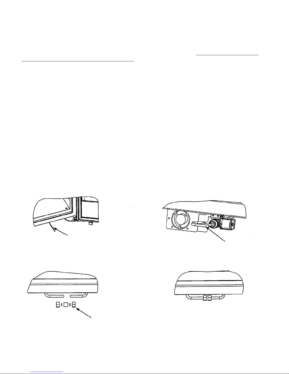
1. Pull copper supply tubing from plumbing forward from underneath unit (see Figure A).
2. Flush air and impurities from water line by turning on water supply and running two (2) quarts (1.9 L) of water into a
bucket.
3. Bend the open end of the supply tube to point toward the open end of the Water Valve Tube (see Figure B). Note:
The Water Valve Tube is designed to flex or bend as necessary to line up with the supply tube, so union can be
connected easily.
4. Remove brass nuts and ferrules from union and slide onto open ends of Water Valve Tube and supply tubing (see
Figure C).
5. Connect nuts on copper tubing to union (see Figure D). Be sure both nuts are fully seated in union before tightening
nuts. Do Not over tighten.
6. Turn on water supply to unit and check for leaks.
7. Turn off water supply to unit and correct any leaks. Repeat this process until no leaks exist.
8. Completely turn on water supply to unit.
9. Verify drain pan is installed and aligned. Drain pan must be pushed past and over initial stopping point.
Figure A
Figure B
Copper tubing
Water valve tube
Figure D
Figure C
Brass nuts and
ferrules
Page 34
34
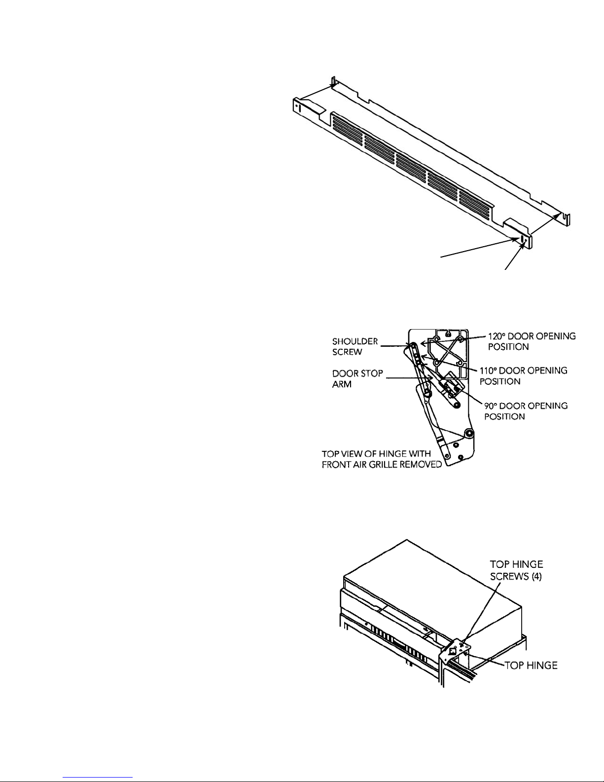
Align the holes on both ends of the louvered panel
with the holes in the base of the unit.
Adjust the kickplate to the desired height and fasten
in place by tightening the screws in the slot. Attach
the kickplate to the unit on each side with the two
black phillips head screws provided.
Attach to unit with
screws
(on both ends)
Slots for
adjustments (on
both ends)
KICKPLATE INSTALLATION
DOOR STOP ADJUSTMENT
1. Remove center grille louver from the top air grille
assembly.
2. Remove top air grille by removing (2) 1/4” screws with an
8” (20.3 cm) long magnetic 1/4” (.6 cm) nut driver. Pull
assembly forward.
3. Open refrigerator door so door stop arm and shoulder
screw are accessible. Shoulder screws should be in 110
o
door opening position.
4. Remove shoulder screw and place shoulder screw in the
90
o
or 120odoor opening position.
5. Replace top air grille assembly.
HINGE ADJUSTMENT
Verify proper door alignment. Only the top hinge is adjustable.
1. Remove the center grille louver from the top air grille
assembly.
2. Remove top air grille by removing (2) 1/4” screws with an 8”
(20.3 cm) long magnetic 1/4” (.6 cm) nut driver. Pull
assembly forward.
3. Loosen the (4) top hinge screws.
4. Align refrigerator door by lifting.
5. Tighten screws.
6. Replace top air grille assembly
Page 35
35
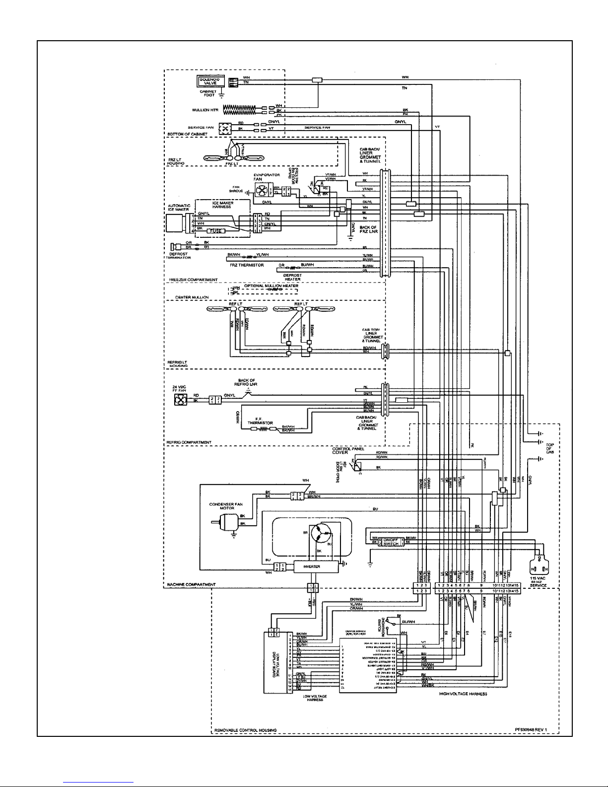
WIRING DIAGRAM
BUILT-IN 36” W. BOTTOM MOUNT REFRIGERATOR/FREEZER
WWAARRNNIINNGG::
EELLEECCTTRRIICCAALL
GGRROOUUNNDDIINNGG
IINNSSTTRRUUCCTTIIOONNSS
This appliance is equipped
with a three prong
grounding plug for your
protection against shock
hazard and should be
plugged directly into a
properly grounded three
prong receptacle. DO
NOT CUT OR REMOVE
THE GROUNDING PRONG
FROM THIS PLUG.
RREEFFEERR OONNLLYY TTOO
FFEEAATTUURREESS WWHHIICCHH AARREE
EEQQUUIIPPPPEEDD WWIITTHH TTHHIISS
UUNNIITT..
Page 36

VIKING RANGE CORPORATION
111 Front Street • Greenwood, Mississippi 38930 USA • (662) 455-1200
Specifications subject to change without notice
F20353
(PS0705VR)
 Loading...