

Viking Range VCFB304, VCRB304, VCFB364, VCRB364, DDFB304 Installation Instructions Manual
...
IiNSTALLATION
STRUCTIONS
BUILT-IN ALL REFRIGERATOR/ALL FREEZER
Retain for Future Reference
IMPORTANT - PLEASE READ AND FOLLOW
VIKING RANGE CORPORATION
111 Front Street
Greenwood, Mississippi 38930 USA
(662) 455-1200
Make sure that incoming voltage isthe same as unit rating. An electric rating plate specifying voltage, frequency, wattage,
amperage, and phase isattached to the product.
To reduce the risk of fire, electric shock, or injury to persons, installation work and electrical wiring must be done by qualified
people in accordance with all applicable codes and standards, including fire-rated construction.
The installer should leave these instructions with the consumer who should retain them for local inspector's use and for
future reference.
GENERAL INFORMATION
Your safety and the safety of others
is very important.
We haveprovided many important safety
messagesin this manual and on your
appliance. Always read and obey all
safety messages.
This isthe safety alertsymbol. This
symbol alertsyou to hazardsthat
cankillor hurt you and others.
All safety messageswill be
preceded,by the sa!ety,alertsymbol and
the word DANGERor 'WARNING .
Thesewordsmean:
be killed or seriouslyinjured ifyou
don't follow instructions.
You can be killedor seriouslyinjured if
roudon t follow instructions.
Nilsafetymessageswill identify the
hazard,tell you how to reducethe chance
ifinjury,and tell you what can happen if
the instructionsare not followed.
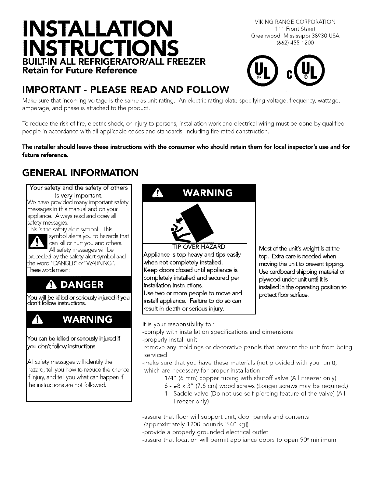
TIP OVER HAZARD
Appliance is top heavyand tips easily
when not completely installed.
Keep doors closed until appliance is
completely installed and secured per
installation instructions.
Use two or more people to move and
install appliance. Failure to do so can
result in death or serious injury.
Most of the unit'sweight isatthe
top. Extracareisneeded when
moving the unit to prevent lipping.
Usecardboard shipping material or
plywood under unit until it is
installedinthe operating pesil_onto
protect floor surface.
It is your responsibility to :
-comply with installation specifications and dimensions
-properly install unit
-remove any moldings or decorative panels that prevent the unit from being
serviced
-make sure that you have these materials (not provided with your unit),
which are necessary for proper installation:
1/4" (6 mm) copper tubing with shutoff valve (All Freezer only)
6 - #8 x 3" (7.6 cm) wood screws (Longer screws may be required.)
1 - Saddle valve (Do not use self-piercing feature of the valve) (All
Freezer only)
-assure that floor will support unit, door panels and contents
(approximately 1200 pounds [540 kg])
-provide a properly grounded electrical outlet
-assure that location will permit appliance doors to open ?0°minimum
BASIC SPECIFICATIONS AND DIMENSIONS - PROFESSIONAL MODELS
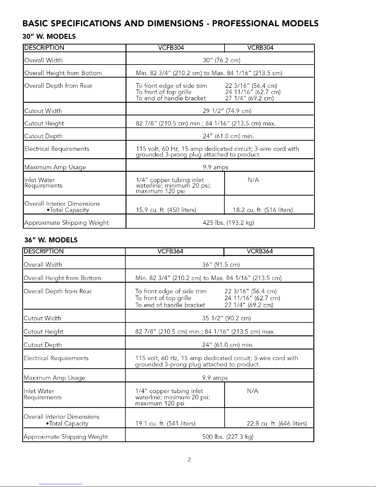
30" W. MODELS
DESCRIPTION
Overall Width
Overall Height from Bottom
Overall Depth from Rear
Cutout Width
Cutout Height
Cutout Depth
Electrical Requirements
VCFB304 VCRB304
30" (76.2 em)
Min. 82 3/4" (210.2 em) to Max. 84 1/16" (213.5 cm)
To front edge of side trim 22 3/16" (56.4 cm)
To front of top grille 24 11/16" (62.7 cm)
To end of handle bracket 27 1/4" (69.2 em)
29 1/2" (74.9 em)
82 7/8" (210.5 cm) min.; 84 1/16" (213.5 cm) max.
24" (61.0 em) min.
11S volt 60 Hz, 1S amp dedicated circuit; 3-wire cord with
grounded 3-prong p ug attached to product.
9.9 am )s
1/4" copper tubing inlet N/A
waterline; minimum 20 psi;
maximum 120 psi
Maximum Amp Usage
Inlet Water
Requirements
Overall Interior Dimensions
•Total Capacity 15.9 cu. ft. (450 liters) 18.2 cu. ft. (516 liters)
Approximate Shipping Weight 425 Ibs. (193.2 kg)
36" W. MODELS
DESCRIPTION VCFB364 VCRB364
Overall Width 36" (91.S cm)
Overall Height from Bottom Min. 82 3/4" (210.2 em) to Max. 84 1/16" (213.5 cm)
Overall Depth from Rear To front edge of side trim 22 3/16" (56.4 cm)
To front of top grille 24 11/16" (62.7 cm)
To end of handle bracket 27 1/4" (69.2 cm)
Cutout Width 35 1/2" (90.2 cm)
Cutout Height 82 7/8" (210.5 cm) min.; 84 1/16" (213.5 cm) max.
Cutout Depth 24" (61.O cm) min.
Electrical Requirements 11S volt, 60 Hz, 1S amp dedicated circuit; 3-wire cord with
grounded 3-prong plug attached to product.
Maximum Amp Usage 9.9 amps
Inlet Water 1/4" copper tubing inlet N/A
Requirements waterline; minimum 20 psi;
maximum 120 psi
Overall Interior Dimensions
•Total Capacity 19.1 cu. ft. (541 liters) 22.8 cu. ft. (646 liters)
Approximate Shipping Weight S00 Ibs. (227.3 kg)
BASIC SPECIFICATIONS AND DIMENSIONS - PROFESSIONAL MODELS
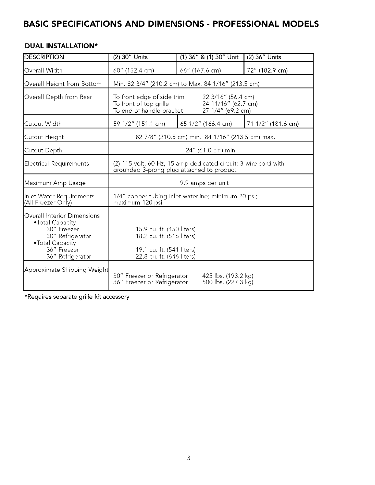
DUAL INSTALLATION*
DESCRIPTION
Overall Width
Overall Height from Bottom
Overall Depth from Rear
Cutout Width
Cutout Height
Cutout Depth
Electrical Requirements
Maximum Amp Usage
Inlet Water Requirements
',All Freezer Only)
Overall Interior Dimensions
°Total Capacity
30" Freezer
30" Refrigerator
°Total Capacity
36" Freezer
36" Refrigerator
Approximate Shipping Weigh1
(2) 30" Units (1) 36" & (1) 30" Unit (2) 36" Units
60" (152.4 cm) 66" (167.6 cm) 72" (182.9 em)
Min. 82 3/4" (210.2 cm) to Max. 84 1/16" (213.5 cm)
To front edge of side trim 22 3/16" (56.4 em)
To front of top grille 24 11/16" (62.7 cm)
To end of handle bracket 27 1/4" (69.2 em)
59 1/2" (151.1 em) 65 1/2" (166.4 cm) 71 1/2" (181.6 cm)
82 7/8" (210.5 cm) min.; 84 1/16" (213.5 cm) max.
24" (61.Ocm) min.
(2) 115 volt, 60 Hz, 15 amp dedicated circuit; 3-wire cord with
grounded 3-prong plug attached to product.
9.9 amps per unit
1/4" copper tubing inlet waterline; minimum 20 psi;
maximum 120 psi
15.9 cu. ft. (450 liters)
18.2 cu. ft. (516 liters)
19.1 cu. ft. (541 liters)
22.8 cu. ft. (646 liters)
30" Freezer or Refrigerator
36" Freezer or Refrigerator
425 Ibs. (193.2 kg)
500 Ibs. (227.3 kg)
*Requires separate grille kit accessory
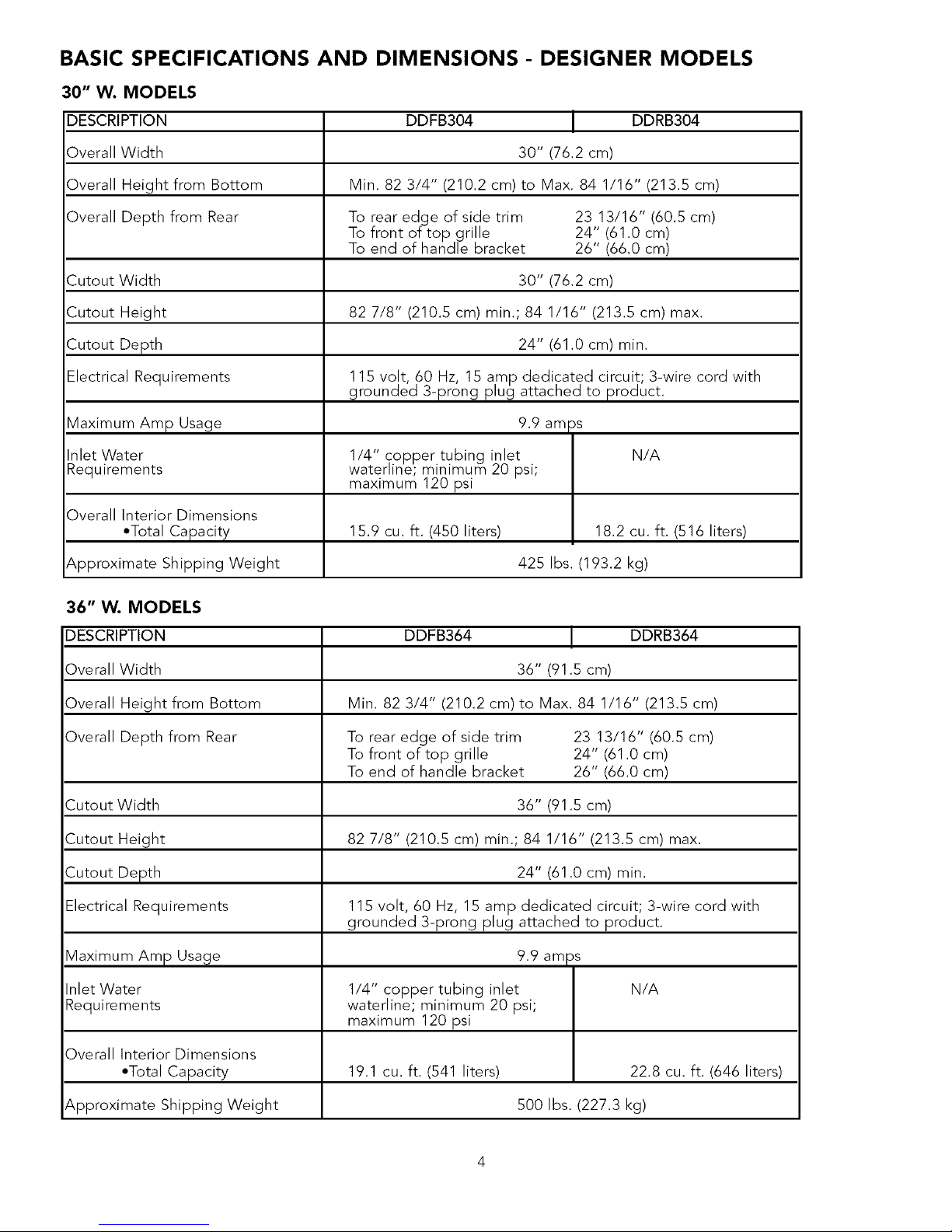
BASIC SPECIFICATIONS AND DIMENSIONS - DESIGNER MODELS
30" W. MODELS
DESCRIPTION
Overall Width
Overall Height from Bottom
Overall Depth from Rear
Cutout Width
Cutout Height
Cutout Depth
Electrical Requirements
Maximum Amp Usage
Inlet Water
Requirements
Overall Interior Dimensions
*Total Capacity
Approximate Shipping Weight
DDFB304 DDRB304
30" (76.2 cm)
Min. 82 3/4" (210.2 cm) to Max. 84 1/16" (213.5 cm)
To rear edge of side trim 23 13/16" (60.5 cm)
To front of top grille 24" (61.0 cm)
To end of handle bracket 26" (66.0 cm)
30" (76.2 cm)
82 7/8" (210.5 cm) min.; 84 1/16" (213.5 cm) max.
24" (61.0 cm) min.
115 volt 60 Hz, 15 amp dedicated circuit; 3-wire cord with
grounded 3-prong p ug attached to product.
9.9 am _s
1/4" copper tubing inlet N/A
waterline; minimum 20 psi;
maximum 120 psi
15.9 cu. ft. (450 liters) 18.2 cu. ft. (516 liters)
425 Ibs. (193.2 kg)
36" W. MODELS
DESCRIPTION
Overall Width
Overall Height from Bottom
Overall Depth from Rear
Cutout Width
Cutout Height
Cutout Depth
Electrical Requirements
Maximum Amp Usage
Inlet Water
Requirements
Overall Interior Dimensions
•Total Capacity
Approximate Shipping Weight
DDFB364 I DDRB364
36" (91 5 cm)
Min 82 3/4" (210.2 cm) to Max 84 1/16" (213.5 cm)
To rear edge of side trim 23 13/16" (60.5 cm)
To front of top grille 24" (61 0 cm)
To end of handle bracket 26" (66.0 cm)
36" (91.5 cm)
82 7/8" (210.5 cm) min.; 84 1/16" (213.5 cm) max.
24" (61.0 cm) min.
115 volt, 60 Hz, 15 amp dedicated circuit; 3-wire cord with
grounded 3-prong plug attached to product.
9.9 am )s
1/4" copper tubing inlet N/A
waterline; minimum 20 psi;
maximum 120 psi
19.1 cu. ft. (541 liters) 22.8 cu. ft. (646 liters)
500 Ibs. (227.3 kg)
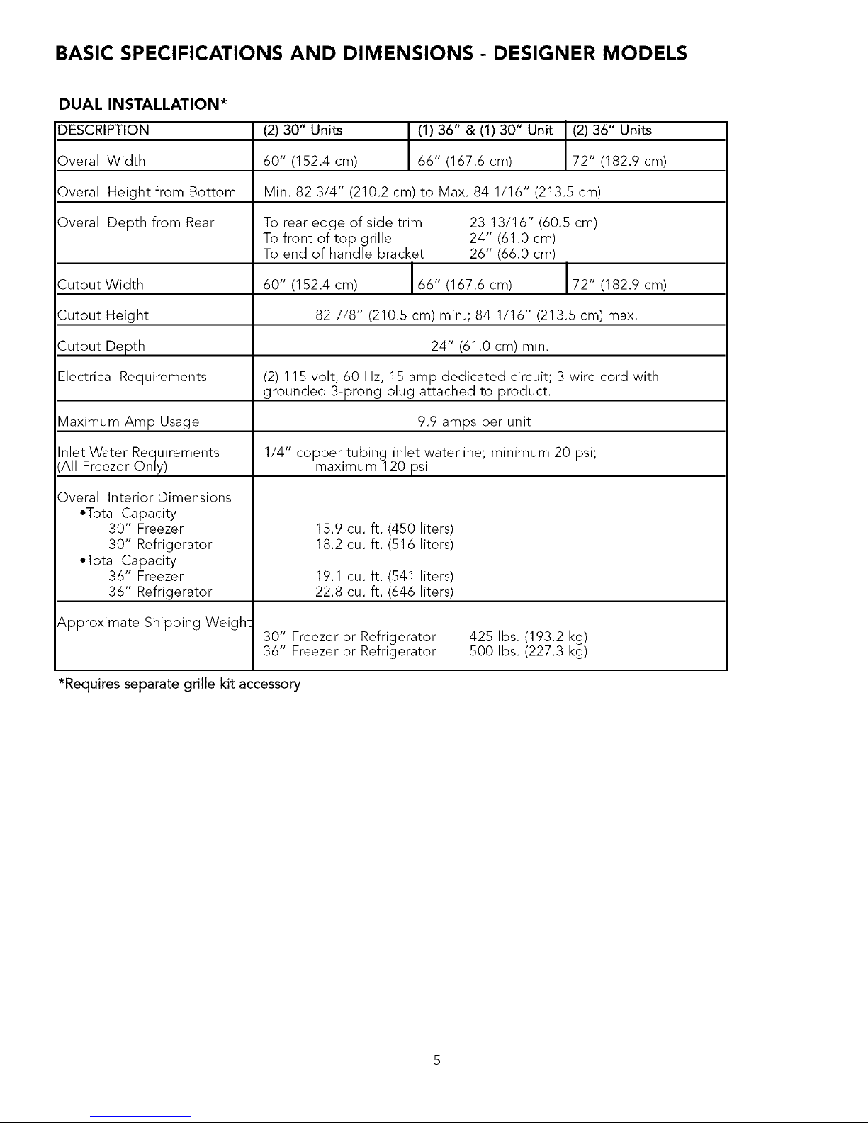
BASIC SPECIFICATIONS AND DIMENSIONS - DESIGNER MODELS
DUAL INSTALLATION*
DESCRIPTION
Overall Width
Overall Height from Bottom
Overall Depth from Rear
Cutout Width
Cutout Height
Cutout Depth
Electrical Requirements
Maximum Amp Usage
Inlet Water Requirements
(All Freezer Only)
Overall Interior Dimensions
•Total Capacity
30" Freezer
30" Refrigerator
•Total Capacity
36" Freezer
36" Refrigerator
Approximate Shipping Weight
(2) 30" Units (1)36" & (1) 30" Unit (2) 36" Units
60" (152.4 cm) 66" (167.6 cm) 72" (182.9 cm)
Min. 82 3/4" (210.2 cm) to Max. 84 1/16" (213.5 cm)
To rear edge of side trim 23 13/16" (60.5 cm)
To front of top grille 24" (61.0 cm)
To end of handle bracket 26" (66.0 cm)
60" (152.4 cm) 66" (167.6 cm) 72" (182.9 cm)
82 7/8" (210.5 cm) min.; 84 1/16" (213.5 cm) max.
24" (61.O cm) min.
(2) 115 volt, 60 Hz, 15 amp dedicated circuit; 3-wire cord with
grounded 3-prong plug attached to product.
9.9 amps per unit
1/4" copper tubing inlet waterline; minimum 20 psi;
maximum 120 psi
15.9 cu. ft. (450 liters)
18.2 cu. ft. (516 liters)
19.1 cu. ft. (541 liters)
22.8 cu. ft. (646 liters)
30" Freezer or Refrigerator
36" Freezer or Refrigerator
425 Ibs. (193.2 kg)
500 Ibs. (227.3 kg)
*Requires separate grille kit accessory
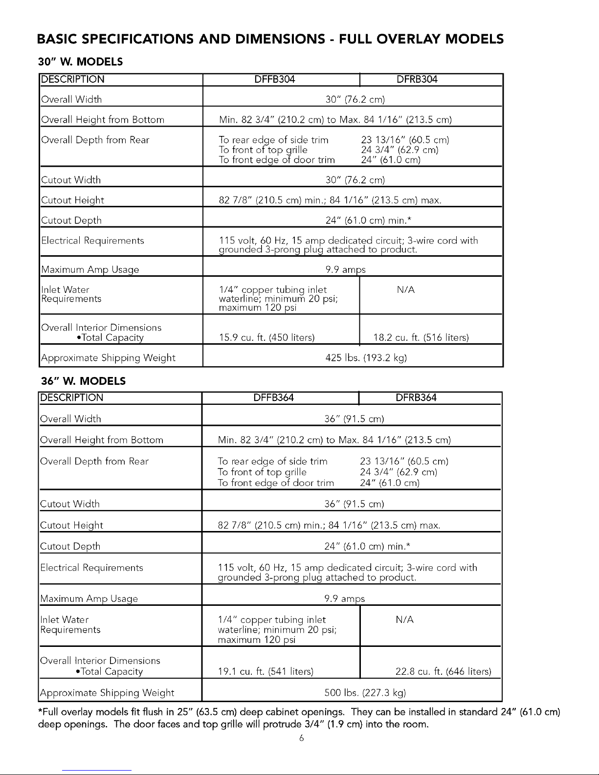
BASIC SPECIFICATIONS AND DIMENSIONS - FULL OVERLAY MODELS
30" W. MODELS
DESCRIPTION
Overall Width
Overall Height from Bottom
Overall Depth from Rear
Cutout Width
Cutout Height
Cutout Depth
Electrical Requirements
DFFB304 DFRB304
30" (76.2 cm)
Min. 82 3/4" (210.2 cm)to Max. 84 1/16" (213.5 cm)
To rear edge of side trim 23 13/16" (60.5 cm)
To front of top grille 24 3/4" (62.9 em)
To front edge of door trim 24" (61.0 cm)
30" (76.2 cm)
82 7/8" (210.5 cm) min.; 84 1/16" (213.5 cm) max.
24" (61.0 em) min.*
115 volt, 60 Hz, 15 amp dedicated circuit 3-wire cord with
grounded 3-prong pug attached to product.
9.9am )s
1/4" copper tubing inlet N/A
waterline; minimum 20 psi;
maximum 120 psi
Maximum Amp Usage
Inlet Water
Requirements
Overall Interior Dimensions
•Total Capacity 15.9 eu. ft. (450 liters) 18.2 cu. ft. (516 liters)
Approximate Shipping Weight 425 Ibs. (193.2 kg)
36" W. MODELS
DESCRIPTION DFFB364 DFRB364
Overall Width 36" (91.5 cm)
Overall Height from Bottom Min. 82 3/4" (210.2 em) to Max. 84 1/16" (213.5 cm)
Overall Depth from Rear To rear edge of side trim 23 13/16" (60.5 cm)
To front of top grille 24 3/4" (62.9 cm)
To front edge of door trim 24" (61.0 cm)
Cutout Width 36" (91.5 cm)
Cutout Height 82 7/8" (210.5 cm) min.; 84 1/16" (213.5 cm) max.
Cutout Depth 24" (61.0 cm) min.*
Electrical Requirements 115 volt, 60 Hz, 15 amp dedicated circuit; 3-wire cord with
grounded 3-prong plug attached to product.
Maximum Amp Usage 9.9 amps
Inlet Water 1/4" copper tubing inlet N/A
Requirements waterline; minimum 20 psi;
maximum 120 psi
Overall Interior Dimensions
•Total Capacity 19.1 eu. ft. (541 liters) 22.8 cu. ft. (646 liters)
Approximate Shipping Weight 500 Ibs. (227.3 kg)
*Full overlay models fit flush in 25" (63.5 cm) deep cabinet openings. They can be installed in standard 24" (61.0 cm)
deep openings. The door faces and top grille will protrude 3/4" (1.9 cm) into the room.
6
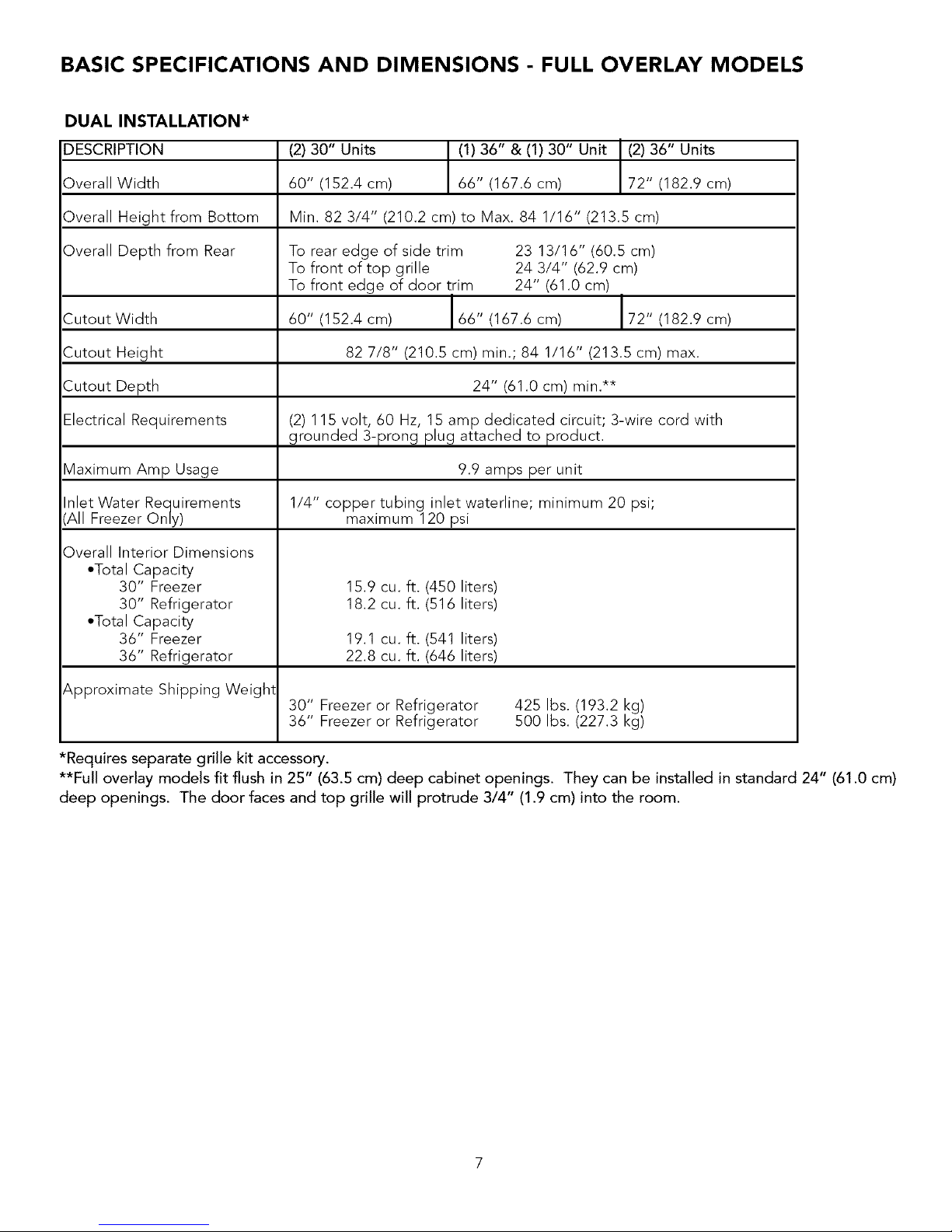
BASIC SPECIFICATIONS AND DIMENSIONS - FULL OVERLAY MODELS
DUAL INSTALLATION*
DESCRIPTION
Overall Width
Overall Height from Bottom
Overall Depth from Rear
Cutout Width
Cutout Height
Cutout Depth
Electrical Requirements
Maximum Amp Usage
Inlet Water Requirements
(All Freezer Only)
Overall Interior Dimensions
*Total Capacity
30" Freezer
30" Refrigerator
*Total Capacity
36" Freezer
36" Refrigerator
Approximate Shipping Weight
(2) 30" Units (1)36" & (1) 30" Unit (2) 36" Units
60" (152.4 em) 66" (167.6 cm) 72" (182.9 cm)
Min. 82 3/4" (210.2 cm) to Max. 84 1/16" (213.5 cm)
To rear edge of side trim 23 13/16" (60.5 cm)
To front of top grille 24 3/4" (62.9 cm)
To front edge of door trim 24" (61.0 cm)
60" (152.4 em) 66" (167.6 cm) 72" (182.9 cm)
82 7/8" (210.5 cm) min.; 84 1/16" (213.5 cm) max.
24" (61.O em) min.**
(2) 115 volt, 60 Hz, 15 amp dedicated circuit; 3-wire cord with
grounded 3-prong plug attached to product.
9.9 amps per unit
1/4" copper tubing inlet waterline; minimum 20 psi;
maximum 120 psi
15.9 cu. ft. (450 liters)
18.2 eu. ft. (516 liters)
19.1 cu. ft. (541 liters)
22.8 cu. ft. (646 liters)
30" Freezer or Refrigerator
36" Freezer or Refrigerator
425 Ibs. (193.2 kg)
500 Ibs. (227.3 kg)
*Requires separate grille kit accessory.
**Full overlay models fit flush in 25" (63.5 cm) deep cabinet openings. They can be installed in standard 24" (61.0 cm)
deep openings. The door faces and top grille will protrude 3/4" (1.9 cm) into the room.
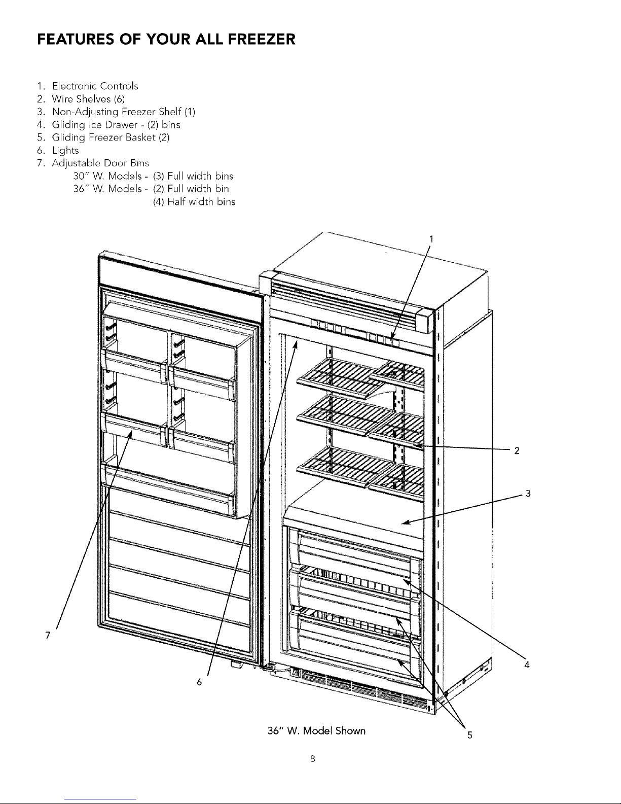
FEATURES OF YOUR ALL FREEZER
1. Electronic Controls
2. Wire Shelves (6)
3. Non-Adjusting Freezer Shelf (1)
4. Gliding Ice Drawer - (2) bins
5. Gliding Freezer Basket (2)
6. Lights
7. Adjustable Door Bins
30" W. Models - (3) Full width bins
36" W. Models - (2) Full width bin
(4) Half width bins
36" W. Model Shown
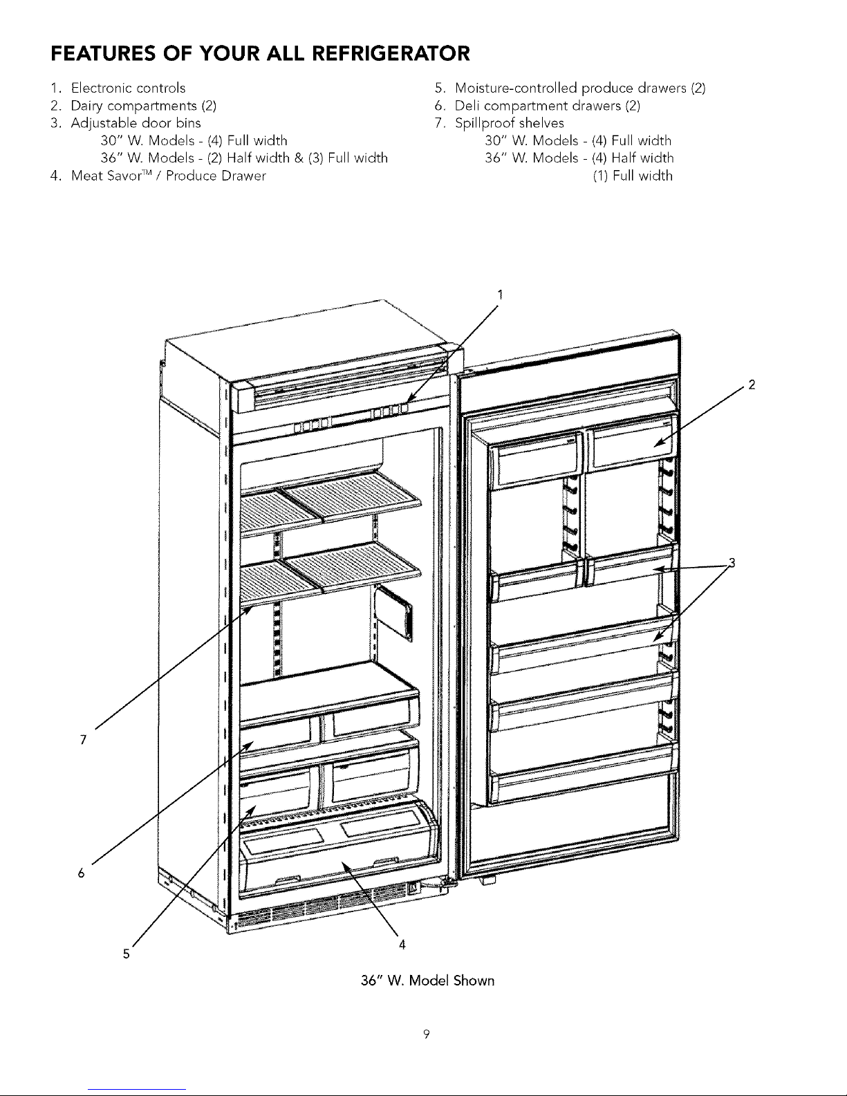
FEATURES OF YOUR ALL REFRIGERATOR
1. Electronic controls
2. Dairy compartments (2)
3. Adjustable door bins
30" W. Models - (4) Full width
36" W. Models - (2) Half width & (3) Full width
4. Meat SavorTM / Produce Drawer
,
6.
7.
Moisture-controlled produce drawers (2)
Deli compartment drawers (2)
Spillproof shelves
30" W. Models - (4) Full width
36" W. Models - (4) Half width
(1) Full width
4
36" W. Model Shown

SITE PREPARATIONS AND CONSIDERATIONS
PROFESSIONAL MODEL ALL REFRIGERATOR/ALL FREEZER
CABINET OPENING DIMENSIONS
i
t
(7.6 cm)
(2) 2"x4" Mounting board
/(1 1/2" [3.8 cm] x 3 1/2" [8.9 cm])
J Note: If unit is installed deeper than 24" (61.0 cm), then shim behind the
anti-tip bracket thickness by the same amount.
I / I <_
I Bottom of anti-tip boardLs 1 I I I
_m/below opening I I I I
I height. I I JIM
_lt m.L_stbe firmly I J Jill
I seated underanti-tip b°ard" I I r
Z
82 7/8" (210.5 cm)min. I I /
841,1_,,_213._)max. 73_,8" E II
anti-tip board and opening height (186.4 cm) I t__ _ "--'_---2 {
Water line entry area
(All Freezer only)
30" W. Professional
36" W. Professional
A B
23" (58.4 cm) 29 1/2" (74.9 cm)
29" (73.7 cm) 35 1/2" (90.2 cm)
10
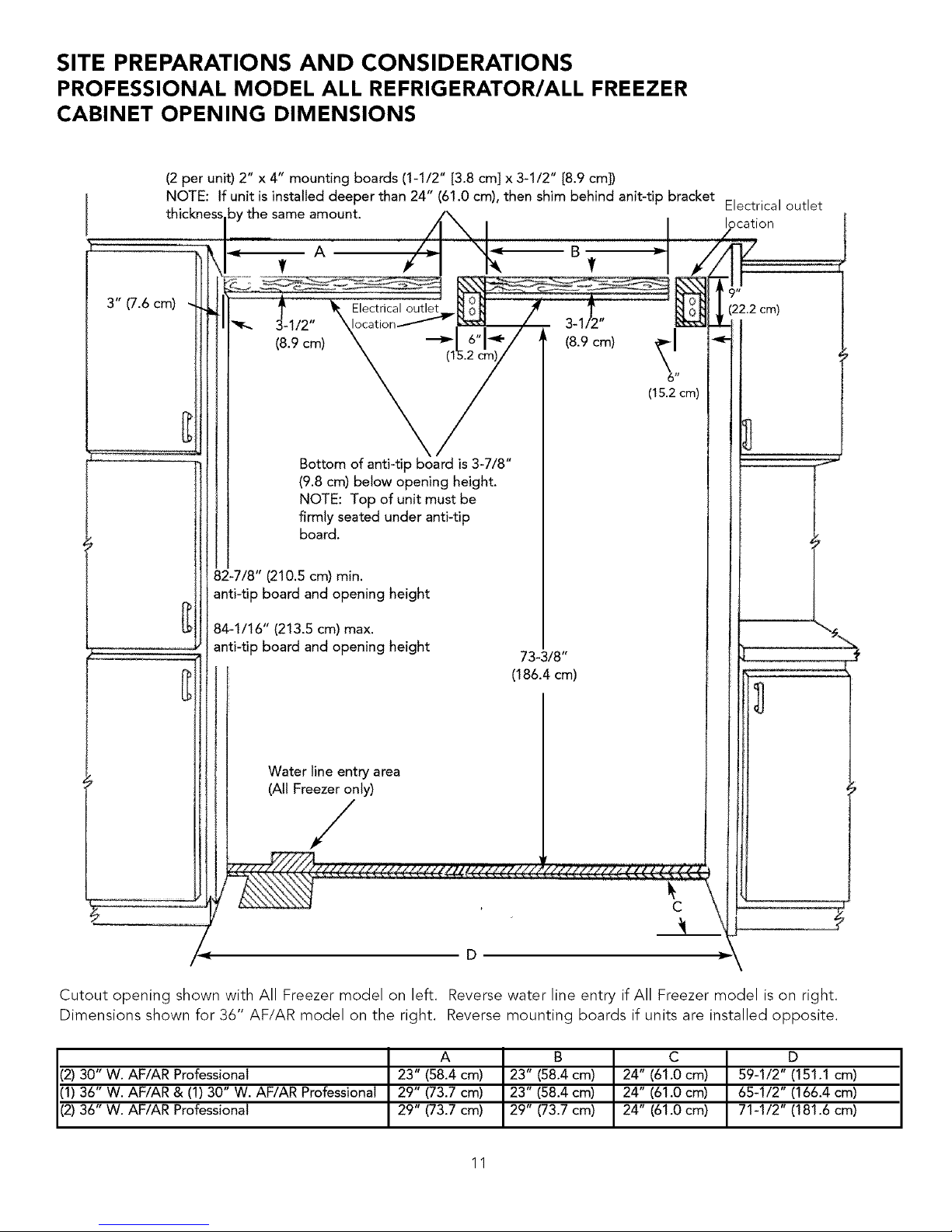
SITE PREPARATIONS AND CONSIDERATIONS
PROFESSIONAL MODEL ALL REFRIGERATOR/ALL FREEZER
CABINET OPENING DIMENSIONS
(2 per unit) 2" x 4" mounting boards (1-1/2" [3.8 cm] x 3-1/2" [8.9 cm])
NOTE: If unit is installed deeper than 24" (61.0 cm), then shim behind anit-tip bracket
by the same amount.
3" (7.6cm)
Electricaloutlet
(8.9 cm)
(1
Bottom of anti-ti F is 3-7/8"
(9.8 cm) below opening height.
NOTE: Top of unit must be
firmly seated under anti-tip
board.
82-7/8" (210.5 cm) min.
anti-tip board and opening height
(213.5 cm) max.
anti-tip board and opening height
Water line entry area
(All Freezer only)
/
(8.9 cm) _61,'
(15.2cm)
73-3/8"
(186.4 cm)
Electrical outlet
)cation
9 II
(22.2cm)
D
Cutout opening shown with All Freezer model on left. Reverse water line entry if All Freezer model is on right.
Dimensions shown for 36" AF/AR model on the right. Reverse mounting boards if units are installed opposite.
A B C D
(2) 30" W. AF/AR Professional 23" (58.4 cm) 23" (58.4 cm) 24" (61.0 cm) 59-1/2" (151.1 cm)
(1) 36" W. AF/AR & (1) 30" W. AF/AR Professional 29" (73.7 cm) 23" (58.4 cm) 24" (61.0 cm) 65-1/2" (166.4 cm)
(2) 36" W. AF/AR Professional 29" (73.7 cm) 29" (73.7 cm) 24" (61.0 cm) 71-1/2" (181.6 cm)
11
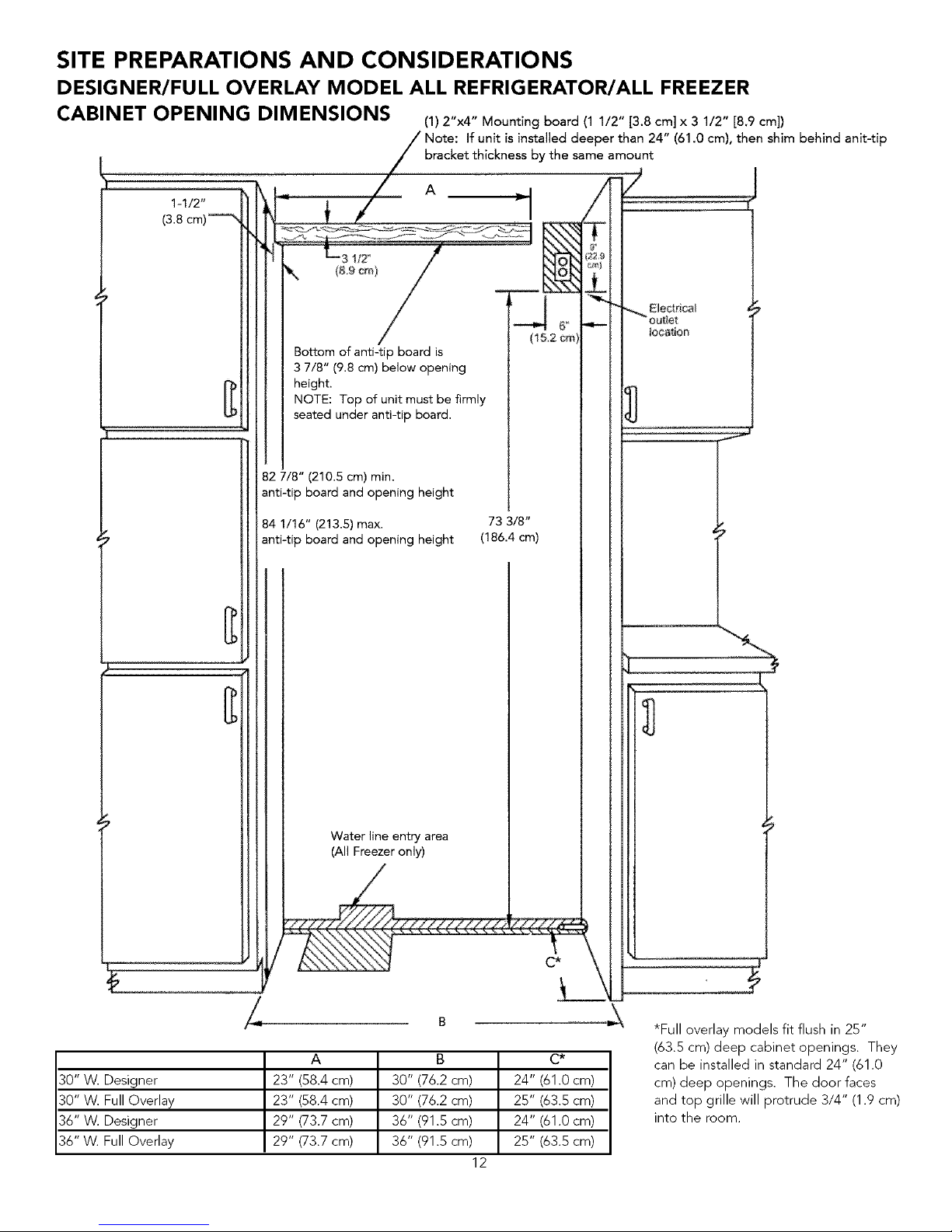
SITE PREPARATIONS AND CONSIDERATIONS
DESIGNER/FULL OVERLAY MODEL ALL REFRIGERATOR/ALL FREEZER
CABINET OPENING DIM ENSIONS (1) 2"x4" Mounting board (1 1/2" [3.8 cm] x 3 1/2" [8.9 cm])
Note: If unit is installed deeper than 24" (61.0 cm), then shim behind anit-tip
bracket thickness by the same amount
Bottom of anti-tip board is
3 7/8" (9.8 cm) below opening
height.
NOTE: Top of unit must be firmly
seated under anti-tip board.
82 7/8" (210.5 cm) min.
anti-tip board and opening height
84 1/16" (213.5) max. 73 3/8"
anti-tip board and opening height (186.4 cm)
Water line entry area
(All Freezer only)
A B C*
30" W. Designer 23" (58.4 cm) 30" (76.2 cm) 24" (61.0 cm)
30" W. Full Overlay 23" (58.4 cm) 30" (7&2 cm) 25" (63.5 cm)
36" W. Designer 29" (73.7 cm) 36" (91.5 cm) 24" (61.0 cm)
36" W. Full Overlay 29" (73.7 cm) 36" (91.5 cm) 25" (63.5 cm)
12
loca#on
*Full overlay models fit flush in 2B"
(63.5 cm) deep cabinet openings. They
can be installed in standard 24" (61.0
cm) deep openings. The door faces
and top grille will protrude 3/4" (1.9 cm)
into the room.
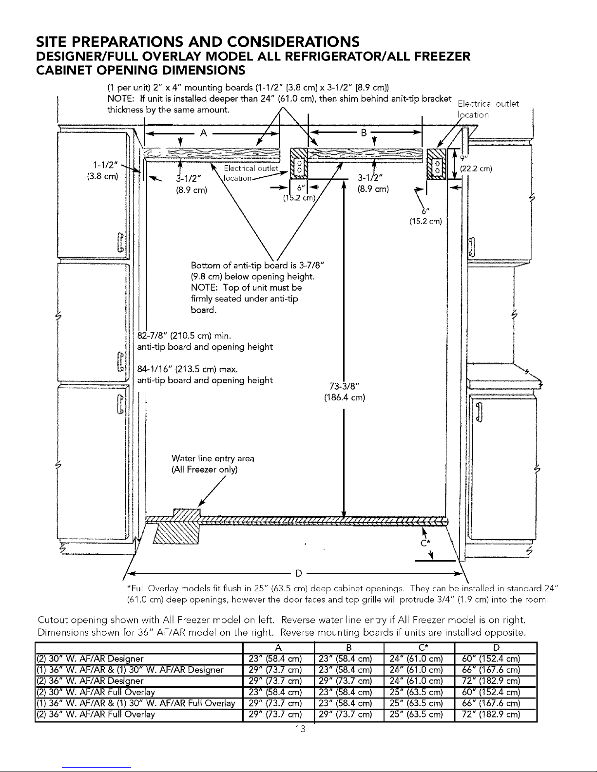
SITE PREPARATIONS AND CONSIDERATIONS
DESIGNER/FULL OVERLAY MODEL ALL REFRIGERATOR/ALL FREEZER
CABINET OPENING DIMENSIONS
(1 per unit) 2" x 4" mounting boards (1-1/2" [3.8 cm] x 3-1/2" [8.9 cm])
NOTE: If unit is installed deeper than 24" (61.0 cm), then shim behind anit-tip bracket Electrical outlet
thickness by the same amount, location
I
A
(3.8cm)
Electrical outlet
(8.9 cm)
(.
\/
Bottom of anti-tip board is 3-7/8"
(9.8 cm) below opening height.
NOTE: Top of unit must be
firmly seated under anti-tip
board.
9 II
(22.2 cm)
82-7/8" (210.5 cm) min.
anti-tip board and opening height
84-1/16" (213.5 cm) max.
anti-tip board and opening height
73-3/8"
(186.4cm)
Water line entry area
(All Freezer only)
/
C*
D
*Full Overlay models fit flush in 25" (63.5 cm) deep cabinet openings. They can be installed in standard 24"
(61.0 cm) deep openings, however the door faces and top grille will protrude 3/4" (1.9 cm) into the room.
Cutout opening shown with All Freezer model on left. Reverse water line entry if All Freezer model is on right.
Dimensions shown for 36" AF/AR model on the right. Reverse mounting boards if units are installed opposite.
A B C* D
(2) 30" W. AF/AR Designer 23" (58.4 cm) 24" (61.0 cm) 60" (152.4 cm)
(1) 36" W. AF/AR & (1) 30" W. AF/AR Designer 23" (58.4 cm) 24" (61.0 cm) 66" (167.6 cm)
(2) 36" W. AF/AR Designer 29" (73.7 cm) 24" (61.0 cm) 72" (182.9 cm)
(2) 30" W. AF/AR Full Overlay 23" (58.4 cm) 25" (63.5 cm) 60" (152.4 cm)
(1) 36" W. AF/AR & (1) 30" W. AF/AR Full Overlay 23" (58.4 cm) 25" (63.5 cm) 66" (167.6 cm)
(2) 36" W. AF/AR Full Overlay 29" (73.7 cm) 25" (63.5 cm) 72" (182.9 cm)
23" (58.4 cm)
29" (73.7 cm)
29" (73.7 cm)
23" (58.4 cm)
29" (73.7 cm)
29" (73.7 cm)
13

WATER SUPPLY REQUIREMENTS - ALL FREEZER MODELS ONLY
Use only 1/4" (6 mm) copper tubing for water line. Do
Not install copper tubing in area where temperatures
J I!l_e SomeELECTRICAL SHOCKHAZARDwatermay remain in line. Electric J dr°p bel°w 3S°F (1"7°C)" Bef°re attaching c°pper tubing
drill must be grounded to prevent severe or to All Freezer, flush at least 2 quarts (1.9 L) of water
lethal shock if water is in line and enters drill through the copper tubing and into a bucket to remove
during use. any particles in the water line.
•Viking Range Corporation is not responsible for property damage due to improper installation or water connection.
•Connect 1/4" (emm) flexible copper tubing to household plumbing in compliance with local codes and ordinances.
•Length of copper tubing must reach from water supply connection to All Freezer connection with an additional length
to facilitate moving the All Freezer out of enclosure for cleaning or service. Tubing should be soft instead of rigid and
ends should be free of burrs.
•Copper tubing route must be above 35°F (1.7°C) to prevent water line from freezing.
•Do not use plastic water lines.
•Do not use the self-piercing feature of a saddle valve. The hole made by the piercing lance is too small for the water
flow rate required by the ice maker. To use a saddle valve, follow the instructions below located under "To rough in
water line" on how to pre-drill a 3/16" (4.5 mm) diameter hole.
•if saddle valve is not used, place a separate shut-off valve in an easily accessible location between water supply and
All Freezer. Do not locate shut-off valve behind All Freezer.
•The installation of Viking All Freezers with an reverse osmosis system is acceptable as long as the water pressure
remains within the allowable PSIas stated below. It is important to note that with many reverse osmosis systems, the
pressure starts off high, but then it decreases as the water level of the reverse osmosis storage area drops. This must
be considered when checking the water pressure coming into the unit.
•Connect a vertical or horizontal 1/2" (1.2 cm) to 1 1/4" (3.2 cm) COLD water line near All Freezer area.
•Run water line through the floor, back, or side wall. Tubing should lay flat on floor underneath All Freezer. Clamp
tubing to wall or floor.
•Water pressure must be greater than 20 psi and less than 120 psi.
To rough in water line:
1. Turn OFF main water supply. Turn ON nearest faucet long enough to clear line of water.
2. Vertical cold water line: Use grounded electric drill or hand drill to drill 3/16" (4.5 mm) hole
in an easily accessible location in water line.
Horizontal cold water line: Use grounded electric drill or hand drill to drill 3/16" (4.5 mm)
hole in the TOP of the water line. This will keep sediment from collecting in valve.
3. Position washer over hole in water line. Turn saddle valve handle clockwise to expose
piercing lance a maximum of 3/16" (4.5 mm). Align piercing lance over hole in water line.
Place both halves of saddle valve bracket against water line. Turn saddle valve handle
clockwise until piercing lance enters hole in water line and is firmly seated. The saddle valve
is now in the closed position. Tighten packing nut. Evenly and firmly tighten bracket screws
so washer will make a water-tight connection. Do not overtighten screws: copper tubing
could be crushed.
4. Check that both ends of copper tubing are cut square. Slide compression nut and sleeve onto copper tubing.
Insert end of copper tubing completely into valve outlet. Tighten compression nut to outlet with adjustable wrench.
Do not overtighten.
5. Turn on main water supply. Check for leaks. Turn saddle valve handle counterclockwise and run 2 (1.9 L) quarts of
water through copper tubing and into a bucket. Turn saddle valve clockwise to shut off water to copper tubing.
6. Route copper tubing to All Freezer area.
7. Leave an additional length of copper tubing coil to facilitate moving the All Freezer out of enclosure for cleaning or
service.
8. See page 37 for water connection instructions.
14

Plumbing Dimensions
*Note: Must be
under 1" (2.5 cm)
from back wall
A B
30" W. Professional 29 1/2" (74.9 cm) 24" (61.0 cm)
38" W. Professional 35 1/2" (90.2 cm) 24" (61.0 cm)
30" W. Designer 30" (76.2 cm) 24" (81.0 cm)
36" W. Designer 36" (91.5 cm) 24" (81.0 cm)
30" W. Full Overlay 30" (76.2 cm) 25" (63.5 cm)
36" W. Full Overlay 36" (91.5 cm) 28" (63.5 cm)
\
Shown
A
Dual Installation
with All Freezer on Left Side. If All Freezer is on Right Side, reverse dimensions
A B
',2)30" W. AF/AR Professional 59 1/2" (151.1 cm) 24" (61.0 cm)
',1)35" W. AF/AR & (1)30" W. AF/AR Professional 65 1/2" (166.4 cm) 24" (61.0 cm)
',2)35" W. AF/AR Professional 71 1/2" (181.6 cm) 24" (61.0 cm)
',2)30" W. AF/AR Designer 60" (152.4 cm) 24" (61.0 cm)
11)38" W. AF/AR & (1)30" W. AF/AR Designer &&"(167.6 cm) 24" (61.0 cm)
12)35" W. AF/AR Designer 72" (182.9 cm) 24" (61.0 cm)
12)30" W. AF/AR Full Overlay 60" (152.4 cm) 2B" (63.5 cm)
11)38" W. AF/AR & (1)30" W. AF/AR Full Overlay 66" (187.6 cm) 2B" (63.5 cm)
12)35" W. AF/AR Full Overlay 72" (182.9 cm) 2B" (63.5 cm)
15

AREA REQUIREMENTS
Verify the following:
• Unit can fit into residence and can be moved around corners and through doorways.
• Floors can support unit's weight plus food weight (approximately 1200 pounds [540 kg] total).
• Rear wall is solid and is able to support two (2) horizontally mounted 2X4s (included) bolted to 2 wall studs.
board bolt heads must be flush with 2X4 to prevent obstruction.
• Remove anything attached to rear or side walls that can obstruct unit installation.
• Cutout dimensions are accurate.
• Electrical outlet is in correct location.
• Water line is in correct location (All Freezer only).
The 2X4
ELECTRICAL REQUIREMENTS
l!_0 ! ELECTRICAL SHOCK HAZARD
Plug into a grounded 3-prong outlet.
DO NOT remove ground plug.
DO NOT use an adapter.
DO NOT use an extension cord.
Failure to follow these instructions could result in
fire or electrical shock.
If codes permit a separate grounding wire to be
used, it is recommended that a qualified electrician
determine that the grounding path is adequate.
Do Not ground to a gas pipe. Check with a
qualified electrician if you are not sure the
appliance is properly grounded. Do Not have a
fuse in the neutral or grounding circuit.
It is the customer's responsibility to:
•contact a qualified electrical installer.
•assure that the electrical installation is adequate and in conformance with the
National Electrical Code, ANSI/NFPA 70-latest edition or Canadian Electrical
Code C22.1-1998 and C22.2 No. 0-M91 (or latest edition), and all local
codes and ordinances. (115 volt, 60-Hz, 15 amp, fused, electrical supply is
required. It is required that a separate circuit serving only this appliance be
provided. This appliance is equipped with a power supply cord having a 3-
prong grounding plug. To minimize possible shock hazard, the cord must be
plugged into a mating 3-prong, grounding-type wall receptacle. Do not use
an extension cord.)
3-PRONG GROUNDING TYPE
WALL RECEPTACLE
3-PRONG
Anti-Tip Requirements
The anti-tip boards should be fastened
into position prior to moving the unit into
the openin 9.
Note: Additional mounting boards may
be required if the unit does not touch
the back wall of the enclosure. To
prevent unit from tipping forward, it
must be secured in place with a solid
soffit or wood block.
TIP OVER HAZARD
Appliance istop heavy and tips easily when not
o_ llcompletely installed.
Keep doors closed until appliance is completely
installed and secured per installation instructions.
Use two or more people to move and install
appliance. Failure to do so can result in death or
serious injury.
16

DOOR SWING CONSIDERATIONS
30" W. PROFESSIONAL MODEL
30"
-_ (76.2 cm)
29"
(73.7 cm)
24-11/16"
(62.7cm)
110.0°
X
120.0 o
.....................................l...............
_;- (40.2 cm) .......
11-7/8"
(30.2 cm)
o3-1/32"
(7.7 cm)
5
52-3/8"
(133.0 cm)
(129.5 cm)
L
2-1/2"
(6.4 cm)
30" W. DESIGNER MODEL
24"
(61.0 cm)
30"
(76.2 cm)
29"
(73.7 cm)
90.0 o
110.0 °
120.0°
15-3/32"
..... (38.3 cm)
10-31/32"
(27.9 cm) _
.1-27/32" I
(4 7 cm)
52-11/32"
(132.9 cm)
5i"
(129.5 cm)
2-1/16"
(5.2 cm)
17

DOOR SWING CONSIDERATIONS
30" W. FULL OVERLAY MODEL
24-314"
(62.9 cm)
30"
...........................(76.2 cm)
29"
(73.7 cm)
|
110.0°
120.0°
13-7/16"
cTn)
8-27/32"
(22.8 crn) /
I-3/32"
(2.8 cm)
53-3/32"
(134.9 crn)
$1-31/32"
(132.0 cm)
S0-5/32"
(127.4 cm)
36" W. PROFESSIONAL MODEL
24-11/16"
(62.7 cm)
36"
(91.4 cm)
35"
(88.9 cm)
90.0 o
110.00
120.0°
]
...........
58-11/32"
(148.2 cm)
56-5/8"
(143.8 cm)
54-7/32"
* \%\ (137.7 cm)
2-1/2"
(6.4 cm)
18

DOOR SWING CONSIDERATIONS
36" W. DESIGNER MODEL
36"
(91.4 cm)
35"
(88.9 cm)
24 _
(61.0 cm)
90.00
\
110.00
\
120.00
36" W. FULL OVERLAY MODEL
_-- 18-3/16"
(46.2 cm)
13-1/8"
....(33.3 cm) _'_
1-27/32"
(4.7 cm)
58-3/8"
(148.3 cm)
i-L 2-1116"
(5.2 cm)
56-11/16"
(144.0 cm)
54-9132"
(137.9 cm)
24-3/4"
(62.9 cm)
36"
...............................................(91.4 cm)
35"
(88.9 cm)
59-5/32"
(150.3 cm)
57-23/32"
(146.6 cm)
19

TIPPING CONSIDERATIONS
30" and 36" W. PROFESSIONAL MODELS
/
/
/
/
/
/
/
/
/
/
/
111-1/16"
(282.1 cm) -._ 24-I1/16" _.oj
(62.7 cm)
-L 11/2.,(3.8 cm)
3-25/32"
(9.6 cm)
86-11/32"
(219.3 cm)
82-3/4"
(210.2 cm)
3-19/32"
(9.1 cm)
82-3/4"
(210.2 cm)
4\
\
C
\
\
\
A B C
30" W. 117W/8" 30" 87-7/8"
(299.4 cm) (76.2 cm) (223.2 cm)
36" W. 126-1/4" 36" 90q/4"
(320.7 cm) (91.5 cm) (229.2 cm)
30" AND 36" W. DESIGNER AND FULL OVERLAY MODELS
/
/
/
/
/
/
109-5/16"
(277.7 cm)
"1_3_25/32 ,,
(9.6 cm)
82-5/8"
(209.9 cm)
82-1/16"
(208.4cm)
24"
(61.0 cm)
3-1/2"
(8.9 cm)
A B C
30" W. 117-7/8" 30" 87-7/8"
(299.4 cm) (76.2 cm) (223.2 cm)
36" W. 126-1/4" 36" 90q/4"
(320.7 cm) (91.5 cm) (229.2 cm)
20
A
\
82-3/4"
(210.2 cm)

ALL REFRIGERATOR/ALL FREEZER OVERALL DIMENSIONS
PROFESSIONAL MODEL
TOP
SIDE
I-1/2 _[(Sacra) 1}-
9o9/!6" (24.3cm)
Z
20-3/4"
(52_7cm)
22-3/16"
(5&4era)
24_!!/16 '_
(62.7cm)
2%1/4'
(69 2cm)
9/32" l
,(0.7 cm)
22 3/16"
(56.4 cm)
t 243/4,,
(62.9 cm)
5/16"
(0.8cm)
(0.8 cm)
FRONT
349/32" (&lcm)
82W/8"
(210.5cm)
Min.
to
_-1116"
(213 5cm)
Max.
75_15/16"
(192.9¢m)
A B C
30" W 29-1/2"(74.9 cm) 29"(73.7 cm) 30" (76.2 cm)
36" W 35-1/2"(90.2 cm) 35" (88.9 cm) 36"(91.5 cm)
21

CABINET INFORMATION - PROFESSIONAL MODELS
Professional models fit "semi-flush" in standard 24" (61.0 cm) deep cabinet openings. The door face protrudes 2-1/2"
(6.4 cm) from the cabinet face. The handle protrudes an additional 2-1/2" (6.4 cm)into the room
A
_/4" (1.9 cmi
FULLEND
PANEL_
DETAIL B_B
COUNTE£TOP
OVERHANG
30"W
36"W
A
29-1/2" (74.9 cm)
35-1/2" (90.2 cm)
22

CABINET INFORMATION - PROFESSIONAL MODELS (Cont'd)
%13/t;6" (4.6,
SPACE IF 24
STANDARD
DEPTH IS USED
!4" (61.0 cm)
STANDARD
CABINET
DEPTH
D_AIL CoC
PARTIAL OVE RL,_Y
_BINET DOOR
A
30" W 29-1/2" (74.9 cm)
36" W 35-1/2" (90.2 cm)
23

CUSTOM SIDE PANEL DIMENSIONS - PROFESSIONAL MODELS
FOR 3/4" (1.9 cm) SIDE PANELS
3/16 _(0,5 cml
THICK BACK
FILLERPANEL
-,.Jl
3/4" (1_9cm) THICK END PANEL
3[I6"
(g'Slcm) t_,f,__ 22_7/16_
t I 13/4 " (i 9 cm!
5132"
(0,4cm)
Optional kickptate notch-
Dimensions determined
by cabinets
S° (152cm) " "_
(56.5 cm)
RIGHT SIDE PANEL
(_/_6 _
5 ¢m)
o7116"
6_(15,2 cm)
(0.4 cm)
82-7/8" (210.5cm) to
84-1/16" (213.5 cm)
Depending on how
high leveling feet are
raised and cabinet
enclosure height
6" (15.2 cm)
|
--221,4 -4Xt
(56_5crn) "\Optional kicKplate notch-
Dimensions determined
by cabinets
LEFT SIDE PANEL
24

ALL REFRIGERATOR/ALL FREEZER OVERALL DIMENSIONS
DESIGNER MODELS
TOP
30"W
36"W
A
B
A
30"(76.2 cm)
36"(91.5 cm)
B
29"(73.7 cm)
35" (88.9 cm)
23 13/16_
SIDE
! lf2"(38cm) -
I
9o9/16" (24,3cm)
t
20-3/4"
(52.7cm)
....... 23_13/16'*
(60.5cm)
24_
(61,0cm)
(66.0cm)
FRONT
t
3-1/2" (8.9cm)
82o718"
(210.5cm)
Min.
to
84-I116"
(213,5cm)
Max.
75-15/i6"
(192,9cm)
_A _
._mmmm_
25

CABINET AND PANEL INFORMATION - DESIGNER MODELS
Designer models fit flush in standard 24" (61.0 cm) deep cabinet openings with no protrusion into the room except 2"
(5.1 cm) curved handle depth
F--
DOOR
DOOR
A
1_(2.5¢m) SPACEIF 25" (635 cm}
STANDARD CABINET DEPTH ,SUSED
/d_ 3/4_ (1<9cm)
,// FULL END
¢63,5_ml
4_(61.0cm)
STANDARD
CABINF
DEPTH
// L
//
//
Z/
J TL
| CABINET FRONt
COUNTERTOP DEPTH-'_
///J
//
A
30" W 30"(76.2 cm)
36" W 36"(91.5 cm)
A
(1.9cm) SPACEIF 24" (6i .0 cm)
STANDARD CAbiNET DEPTH ISUSED
i;
26

ALL REFRIGERATOR/ALL FREEZER OVERALL DIMENSIONS
FULL OVERLAY MODELS
A
TOP
B
SIDE
(LOCALLY SUPPUED HANDLE)
THIS DIMENSION VARIES
i I
9-5/32"
(23 3cm)
t
r
20-3i4"
(52.7cm)
_-- 23_13/16"
(60.5cm}
24_3f4" --
(62 9cm)
(LOCALLY SUPPLIED PANEL)
A B
30"W 30"(76.2 cm) 29"(73.7 cm)
36" W 36"(91.5 cm) 35"(88.9 cm)
FRONT
, k A
3-1/2" (&9cm)
82-7/8"
(210.5cm)
Min,
to
84-1/16"
(213,5cm)
Max,
75-15/16"
(192.9cm)
27

CABINET AND PANEL INFORMATION - FULL OVERLAY MODELS
Full overlay models, (with 3/4" [1.9 cm], thick panels and custome handles locally supplied), fit flush in 25" (63.5 cm) deep (countertop
depth) cabinet openings with no protrusion into room except custom handles
A A
PANEL
25" (63_5 crn}
CABb_ET
DEPTH
3/4" (1.9 era)
i DOOR
OVERLAYPANED-_J } / " (06 m}
BASEPANEL
CUSTOMHAND_ _-;
DETAIL "A"
114"(06 era)
BASEPANEL
A
30" W 30"(76.2 crn)
36" W 36"(91.5 crn)
FLUSH
COUNTERTOPDEPTH
DETAIL "B"
CABINET
DEPTH
28

CABINET AND PANEL INFORMATION - FULL OVERLAY MODELS
(CONTINUED)
Full overlay models can be installed in standard 24" (61.0 cm) deep openings. However,the door facesand top ventilation grille
will protrude 3/4" (1.9 cm)into the room. Thisis ideal for alignment with full overlay cabinet doors.
WA _ NO SPAC£_iF 24_`(610 _m) STANDA_
I | _[,/"A STANOARD |
I I 1 IVA CAB_N_r /
9 ( _ Ig't 243)4"
I' ' (629 _m}
_E PA ......
X
!
3/4" _I, _) A3',IEL %,-,, NEFRIGERATONANI)
_N_ DOOR FLUSH
DI_TAILC
29

CUSTOM DOOR PANEL DIMENSIONS - FULL OVERLAY MODELS
30" W. MODELS
I_ 3/4" (I_9era)FU_ OVERLAY PANEL
-_ _IJ4 °_o6_m!_,sEPA.EL
_ 1.1!s ,,_u[_:_=,............,ii
, [
112" : ',
Illch :
: !
751/4"
I 11! : ::
i i
//1t ' '
t !11 : :
1 I t
i i:
_ 29 114"
118" {0.3 a11) (74.3 cm)
TYP Four Sides
1/4" (0.6 cm)
Base Panel
3/4" (1.9 cm)
Full Overlay
Panel
1/8" (0.3 cm)--_- I_-_ t
SECTION A-A
SHOWN AS MOUNTED ON DOOR
NO SCALE
36" W. MODELS
_ 3/4." (1,9 cm) PJLL OVERLAY PANEL
,,_ _1/4 (0,6 cm) BASE PANEL
_-_m_ 1 ,"_""_"-'222"::" ._.uL.._,,,,,,,,,,
11t751,'2:
II I{191.8cm ,
75 1
_,9,,om,II! A ! A
I i
i t
t I
t I
J
i I
t i
'_ 35 1t4"
1/8" (03 cm) (89,5 _)
TYP Four Sides
DOOR
1/4" (0.6 cm)
Base Panel
3/4" (1.9 cm)
Full Overlay
Panel
1/8" (0.3 cm),=_- I_ t
SECTION A-A
SHOWN AS MOUNTED ON DOOR
NO SCALE
30

DOOR PANEL INSTALLATION
FULL OVERLAY MODELS
1. Remove cabinet side trim with a phillips
screwdriver.
2. Remove handle-side door trim with a phillips
screwdriver.
3. Install "Z" brackets (see below for details).
4. Align panel in door trim and push evenly. For
smoother installation, apply liquid soap to door
trim and "Z" brackets.
5. Install handle-side door trim with screws. Install
door trim inserts (supplied) on top and both sides
of door by starting in one corner and pushing the
strip in place.
6. Install cabinet trim.
!....... _WALL
S/4" (1,9 cm) OVERLAYPANEL--
t/4 _{06 era) BASEPANEL
"Z" BRACKET INSTALLATION - FULL OVERLAY MODELS
1/4 _ {0,6 cm)
BASEPANEL
DOOR
,L_q I F
1/2_'
(t,3cm)
ALL Z-BRACKETS
MOUNTED FLUSHW_TH
(0.2cm)
OFF EDGE OF 1,/4_(06 cm}
BASEPANEL
3/4_ (1.9 ¢m)
FULLOVERLAY
PANEL
RAISED
PANI
-- DOOR TRIM
NSER_ (MOUNT!NG
SCREWS LOCATED
Bg_HiND)
SECTION A-A
CUSTOM-RAiSED PANELS
ATfACNED TO 1/4" (0,6cm)
BASEPANEL
Z-BRACKET MOUNTING _'_
Z-BRACKET MOUNTED TO |
ALL 4 EDGES k_
REAR OF
ALL FREEZER OR
ALL REFRIGERATOR
DOOR PANEL
SECTION A-A
3/4_ (19 cm} FULLOVERLAY
PANELATTACHED TO
1/4'_(06 cm) BASEPANEL
3/4" (1.9 cm) Overlay Panel
1/4" (0.6 cm) Base Panel
31

CUSTOM SIDE PANEL DIMENSIONS
DESIGNER/FULL OVERLAY MODELS
FOR 3/4" (1.9 cm) SIDE PANELS
NOTE: Adding a 314" (I .9 cm) side panel adds an additional 314"(I .9 cm) to the overall width of the product for each
side panel used.
NOTE: Requires side panel hardware kit (Kit Model Number - SPHKDS)
RACKET
÷
3/4 _ (1 9 cm} END PANEL
Z BRACKEZ _t_
(FROM Ill I I
HARDWAREKIT_IIIII
/
OPTIONAL KICKPLATE
NOTCH, DIMENSIONS
DETERMINED BY
CAB NETS
--I14 _ (06 cm} BACK FILLER PANEL
21_3/4_ _ ['---(0._cm)'--" 1
/ Css,2cm)/ | 1 I"
_a
_J
24"
(61.0_m)---'->
R_GHTSIDEPANEL
I
!!
|
24"
LEF SIDEPANEL
3/4**
82-7/8" (210.5 cm) to 84-1/16" ( 213.5 cm)
DEPENDING ON HOW HIGH LEVELING
FEET ARE RAISED, AND CABINET
ENCLOSURE HEIGHT
_%"N'- O PTIO NAL KICKPLATE
NOTCH, DIMENSIONS
DETERMINED BY
CABNETS
32

UNIT INSTALLATION
Use two or more peop e to move
unit. Failure to follow this instruction can result
in back or other injury. To avoid personal injury,
wear gloves when performing any installation
procedure and wear eye protection when
cutting metal straps.
TIP OVER HAZARD
Appliance istop heavy and tips easily
when not completely installed. Keep
doors closed until appliance is
completely installed and secured per
installation instructions. Use two or
more people to move and install
appliance. Failure to do so can result
in death or serious injury.
Most of the unit's weight is at the top. Extra care Is needed when moving the unit to prevent tipping. Do Not
remove protective film until unit is in operating position. All four leveling legs must contact the floor to support and
stabilize the full weight. Do not drop unit.
1, Remove exterior shipping materials prior to moving unit into
home. Remove top and bottom strap (see Figure 1),
2. Remove top cap (see Figure 1).
3. Cut carton rear approximately 1/4" (0.6 cm) to 1" (2.5 cm)
from right corner (see Figure 2) with a utility knife extended
1/4" (0.6 cm). Remove carton and exterior packaging. Save
cardboard shipping material to protect floor surface when
installing unit. Do not remove nylon cord from power cord.
Remove anti-tip board, kiekplate and door trim pieces (DF
models) from rear of unit
(see Figure 3),
4. Remove shipping brackets from skid
by removing 4 bolts (2 each side) with
a 1/2" socket head screwdriver (see
Figure 4).
*Tilting unit is not required to remove
shipping brackets.
5. Slip cart between unit and skid.
Remove unit from skid. Use excess
packaging to protect decorative trim.
Verify that leveling legs are up (0"
adjustment) (see
Figure 5).
6. To avoid floor damage,
use protective material
(see Figure 6).
BACK VtEW
I II II II II II
Figure 1
Figure 3
ANTI-TiP BOARD
DOOR TRIM PIECES
-(DF Models Only)
KICKPLATE
Figure 5
PROTECT TR_M FROM
FRONTLEVELINGLEGS(2)
Y
SKID
Figure 2
I
i
|
I
I
1
|
|
!
i
BACK VIEW
Figure 4
7/16" (11 cm) BOLT
Figure 6
PROTECT FLOOR
33

Electrical Shock Hazard
Disconnect power at breaker or turn power disconnect switch to OFF position before
performing any installation procedure. Failure to do so can result in death or electrical
shock.
OPTION 1
SECURING THE UNIT (3 OPTIONS)
OPTION 1
If a solid soffit is 1" (2.5 cm) or less above the unit, anti-tip boards are not required.
OPTION 2
If a solid soffit is not available or soffit is more than 1" (2.5 cm) above unit, center
wood boards on rear wall 1/4" (.6 cm) maximum above unit. Attach wood boards to
wall studs with six of the provided wood screws, making sure that screws are engaged
in wall studs 1 1/2" (3.8 cm) minimum.
OPTION 3
Create "L" bracket assembly by securing "L" brackets to each end of (1) 2x4 with
provided screws (Item A). If 2x4 does not extend 2" (5.0 cm) beyond rear ledge,
attach (1) 2x4 to wall (Item B), attach (1) 2x4 to rear ledge of cabinet (Item C) and
attach "L" bracket assembly to 2x4 mounted on wall (Item A).
OPTION 2
OPTION 3
Solid Se_
(ITEM C)
o_ lese
!_,--Rear Wa|l
34
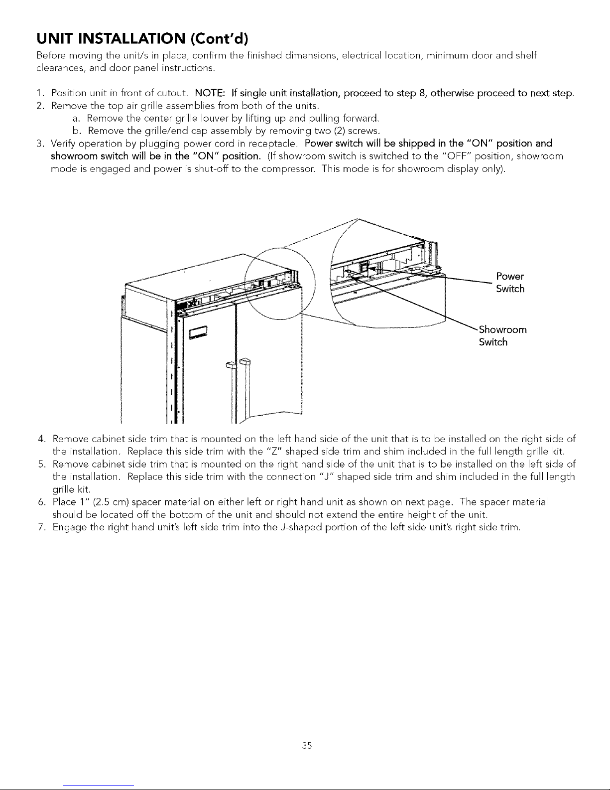
UNIT INSTALLATION (Cont'd)
Before moving the unit/s in place, confirm the finished dimensions, electrical location, minimum door and shelf
clearances, and door panel instructions.
1. Position unit in front of cutout. NOTE: If single unit installation, proceed to step 8, otherwise proceed to next step.
2. Remove the top air grille assemblies from both of the units.
a. Remove the center grille louver by lifting up and pulling forward.
b. Remove the grille/end cap assembly by removing two (2) screws.
3. Verify operation by plugging power cord in receptacle. Power switch will be shipped in the "ON" position and
showroom switch will be in the "ON" position. (If showroom switch is switched to the "OFF" position, showroom
mode is engaged and power is shut-off to the compressor. This mode is for showroom display only).
Power
Switch
-Showroom
Switch
4. Remove cabinet side trim that is mounted on the left hand side of the unit that is to be installed on the right side of
the installation. Replace this side trim with the "Z" shaped side trim and shim included in the full length grille kit.
5. Remove cabinet side trim that is mounted on the right hand side of the unit that is to be installed on the left side of
the installation. Replace this side trim with the connection "J" shaped side trim and shim included in the full length
grille kit.
6. Place 1" (2.5 cm) spacer material on either left or right hand unit as shown on next page. The spacer material
should be located off the bottom of the unit and should not extend the entire height of the unit.
7. Engage the right hand unit's left side trim into the J-shaped portion of the left side unit's right side trim.
35
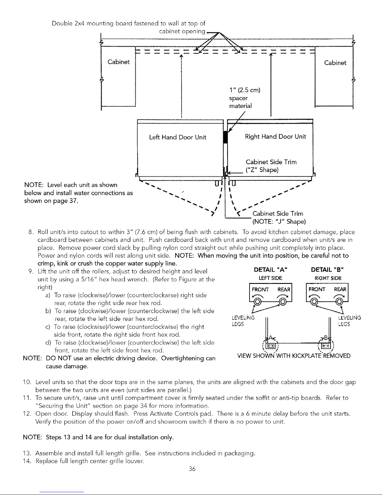
Double 2x4 mounting board fastened to wall at top of
cabinet op
Cabinet
1" (2.5 cm)
spacer
material
Cabinet
NOTE: Level each unit as shown
below and install water connections as
shown on page 37.
Left Hand Door Unit
i1
7
iT Right Hand Door Unit
Cabinet Side Trim
e--- ("Z" Shape)
! U 4,"
s
i s
Cabinet Side Trim
(NOTE: "J" Shape)
8. Roll unit/s into cutout to within 3" (7.6 cm) of being flush with cabinets. To avoid kitchen cabinet damage, place
cardboard between cabinets and unit. Push cardboard back with unit and remove cardboard when unit/s are in
place. Remove power cord slack by pulling nylon cord straight out while pushing unit completely into place.
Power and nylon cords will rest along unit side. NOTE: When moving the unit into position, be careful not to
crimp, kink or crush the copper water supply line.
9. Lift the unit off the rollers, adjust to desired height and level
unit by using a 5/16" hex head wrench. (Refer to Figure at the
right)
a) To raise (clockwise)/Iower (counterclockwise) right side
rear, rotate the right side rear hex rod.
b) To raise (clockwise#lower (counterclockwise) the left side
rear, rotate the left side rear hex rod.
c) To raise (clockwise)/Iower (counterclockwise) the right
side front, rotate the right side front hex rod.
d) To raise (clockwise)/Iower (counterclockwise) the left side
front, rotate the left side front hex rod.
NOTE: DO NOT use an electric driving device. Overtightening can
cause damage.
DETAIL "A" DETAIL "B"
LEFT SIDE RII3HT SIDE
[FRONT REARl IFRONT REAR
LEVELING LEVELING
LEGS _A_ !?BI LEGS
VIEW SHOWN'WITH KICKPLATEREMOVED
10. Level units so that the door tops are in the same planes, the units are aligned with the cabinets and the door gap
between the two units are even (unit sides are parallel.)
11. To secure unit/s, raise unit until compartment cover is firmly seated under the soffit or anti-tip boards. Refer to
"Securing the Unit" section on page 34 for more information.
12. Open door. Display should flash. Press Activate Controls pad. There is a 6 minute delay before the unit starts.
Verify the position of the power on/off and showroom switch if there is no power to unit.
NOTE: Steps 13 and 14 are for dual installation only.
13. Assemble and install full length grille. See instructions included in packaging.
14. Replace full length center grille louver.
36

WATER CONNECTION - ALL FREEZER MODELS
*Refer to water supply requirement section for preliminary installation and site preparation (see pages 10-14).
_Do not use plastic water lines between All Freezer and supply. Plastic water lines can fail due to fatigue over time and
cause extensive damage to product and the home.
_Use only 1/4" copper tubing for water line.
*The installation of Viking All Freezers with an reverse osmosis system is acceptable as long as the water pressure
remains within the allowable PSI as stated on page 14. It is important to note that with many reverse osmosis
systems, the pressure starts off high, but then it decreases as the water level of the reverse osmosis storage area
drops. This must be considered when checking the water pressure coming into the unit.
The 1/4" brass compression union is located in the literature packet.
1. Pull copper supply tubing from plumbing forward from underneath unit (see Figure A).
2. Flush air and impurities from water line by turning on water supply and running two (2) quarts (1.9 L) of water into a
bucket.
3. Bend the open end of the supply tube to point toward the open end of the Water Valve Tube (see Figure B). Note:
The Water Valve Tube is designed to flex or bend as necessary to line up with the supply tube, so union can be
connected easily.
4. Remove brass nuts and ferrules from union and slide onto open ends of Water Valve Tube and supply tubing (see
Figure C).
5. Connect nuts on copper tubing to union (see Figure D). Be sure both nuts are fully seated in union before tightening
nuts. Do Not over tighten.
6. Turn on water supply to unit and check for leaks.
7. Turn off water supply to unit and correct any leaks. Repeat this process until no leaks exist.
8. Completely turn on water supply to unit.
9. Verify drain pan is installed and aligned. Drain pan must be pushed past and over initial stopping point.
Figure A
Copper tubing
Figure B
Water valve tube
\
Figure C "Brass nuts and
ferrules
Figure D
37

KICKPLATE INSTALLATION
Align the holes on both ends of the Iouvered panel
with the holes in the base of the unit.
Adjust the kickplate to the desired height and fasten
in place by tightening the screws in the slot. Attach
the kickplate to the unit on each side with the two
black phillips head screws provided.
Slots for
adjustments (on
both ends)
Attach to unit with
screws
(on both ends)
DOOR STOP ADJUSTMENT
1. Using a 3/16" allen wrench, remove door stop pin located in bottom hinge.
2. The pin is factory set 110°. For 120° swing, move the pin to the utmost forward stop hole.
pin to the utmost rear stop hole.
For 90 ° swing, move the
HINGE ADJUSTMENT
1. Using a 3/16" allen wrench, remove the door stop pin located in bottom hinge.
2. Using the height adjustment shim as a wrenching device, rotate the height adjustment bushing counterclockwise to
raise or clockwise to lower the location of the door.
3. When proper adjustment is reached align shim with door stop pin holes and replace door stop pin. Firmly tighten
pin in place.
Door stop
pin
120° 90°
position aosition
38

WIRING DIAGRAM
BUILT-IN 30" W. ALL FREEZER
f
WARNING:
ELECTRICAL
GROUNDING
INSTRUCTIONS
This appliance is
equipped with a
three prong
grounding plug for
your protection
against shock
hazard and should
be plugged directly
into a properly
grounded three
prong receptacle.
DO NOT CUT OR
REMOVE THE
GROUNDING
PRONG FROM
THIS PLUG.
REFER ONLY TO
FEATURES WHICH
ARE EQUIPPED
WITH THIS UNIT.
++
MACHINE COMPARTMENT
TOP WALL
I
R{GHT MOB&
39

WARNING:
ELECTRICAL
GROUNDING
INSTRUCTIONS
This appliance is
equipped with a three
prong grounding plug
for your protection
against shock hazard
and should be
plugged directly into
a properly grounded
three prong
receptacle. DO NOT
CUT OR REMOVE
THE GROUNDING
PRONG FROM THIS
PLUG.
REFERONLY TO
FEATURES WHICH
ARE EQUIPPED WITH
THIS UNIT.
WIRING DIAGRAM
BUILT-IN 30" W. ALL REFRIGERATOR
REMOVABLE CONTROL
_ow VO_TA__,_RNESS
HGH VOLTAGE HARNESS
L
MACHINE COMPARTMENT
TOP WALL_
REFRIG COMP_TME_NT
BOSOM OF CA_|NET
40

WIRING DIAGRAM
BUILT-IN 36" W. ALL FREEZER
WARNING:
ELECTRICAL
GROUNDING
INSTRUCTIONS
This appliance is
equipped with a
three pron 9
groundin9 plug
for your
orotection against
shock hazard and
should be
olugged directly
into a properly
9rounded three
oron 9 receptacle.
DO NOT CUT OR
REMOVETHE
GROUNDING
PRONG FROM
THIS PLUG.
REFER ONLY TO
FEATURES
WHICH ARE
EQUIPPED WITH
THIS UNIT.
r
MACHtNE COMPARTMENT
REFRJGCOMPARTM_4T
BOTTOM OF CABINET
o
<
5
z
<
41

WARNING:
ELECTRICAL
GROUNDING
INSTRUCTIONS
This appliance is
equipped with a
three prong
grounding plug for
your protection
against shock
hazard and should
be plugged directly
into a properly
grounded three
prong receptacle.
DO NOT CUT OR
REMOVE THE
GROUNDING
PRONG FROM THIS
PLUG.
REFER ONLY TO
FEATURES WHICH
ARE EQUIPPED
WITH THIS UNIT.
l-
WIRING DIAGRAM
BUILT-IN 36" W. ALL REFRIGERATOR
N_GH VOLTAG£ HARN£SS RKMOV_BLE CONTROL 8_,,_,, VOLTAGE HARN£SS
I
1
!!
MACHINE COMPARTMENT
F20324
VIKING RANGE CORPORATION
111 Front Street • Greenwood, Mississippi 38930 USA • (662) 455-1200
Specifications subject to change without notice
For more product information, call 1-888-VIKING1 (845-4641), or visit our web site at http://www.vikingrange.com
(PS1004VR)
 Loading...