

Page 1
Installation
GUIDE
5 SERIES
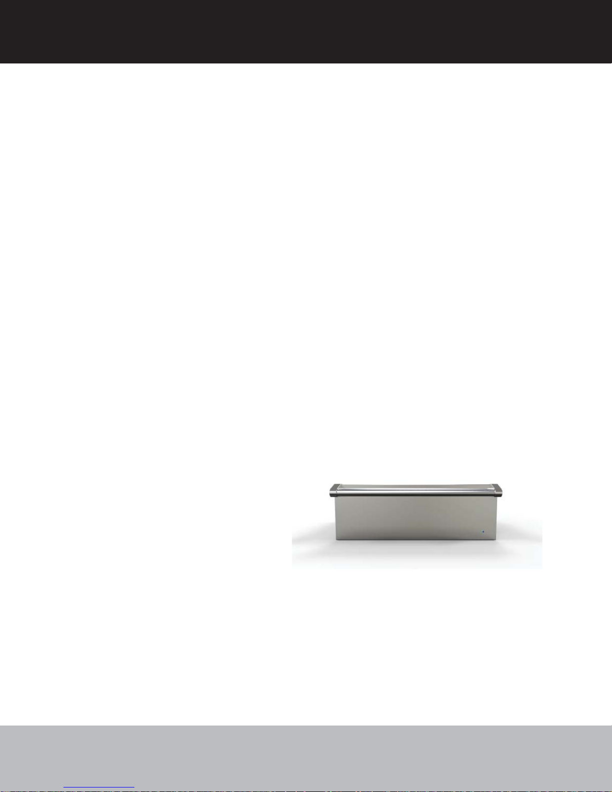
Warming Drawer
VWD527 / CVWD527
VWD530 / CVWD530
1
Page 2
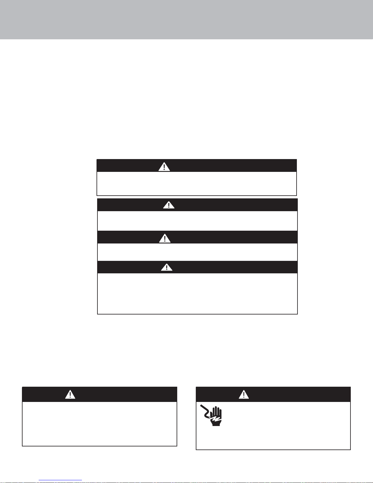
Table of Contents
Important Safety Instructions __________________________________________________________________________ 2
Dimensions _________________________________________________________________________________________ 3
Speci cations _______________________________________________________________________________________ 4
Cutout Dimensions___________________________________________________________________________________ 4
Electrical Requirements _______________________________________________________________________________ 5
General Information __________________________________________________________________________________ 5
Installation _________________________________________________________________________________________ 6
Final Preparation ____________________________________________________________________________________ 7
Service & Registration ________________________________________________________________________________ 7
Important Safety Instructions– Read and Follow!
Before beginning, please read these instructions completely and carefully.
WARNING
If the information in this manual is not followed exactly, a re or explosion
may result causing property damage, personal injury or death.
DANGER
Hazards or unsafe practices which WILL result in
severe personal injury or death
WARNING
Hazards or unsafe practices which COULD result in death or severe
personal injury
CAUTION
Hazards or unsafe practices which COULD result in minor personal
injury.
All safety messages will identify the hazard, tell you how
to reduce the chance of injury, and tell you what can happen if
the instructions are not followed.
• DO NOT remove permanently a xed labels, warnings, or plates from product. This may void the warranty.
• All local and national codes and ordinances must be observed. Installation must conform with local codes, or in the absence
of codes, the National Electrical Code, ANSI/NFPA-70 – latest edition.
• The installer must leave these instructions with the consumer who should retain for local inspector’s use and for future reference.
In Canada: Installation must be in accordance with the current CSA C22.1 Canadian Electrical Codes Part 1 and/or local codes.
WARNING
To reduce the risk of re, electric shock, or injury to
persons, installation work and electrical wiring must
be done by quali ed people in accordance with all
applicable codes and standards, including re-rated
conditions.
WARNING
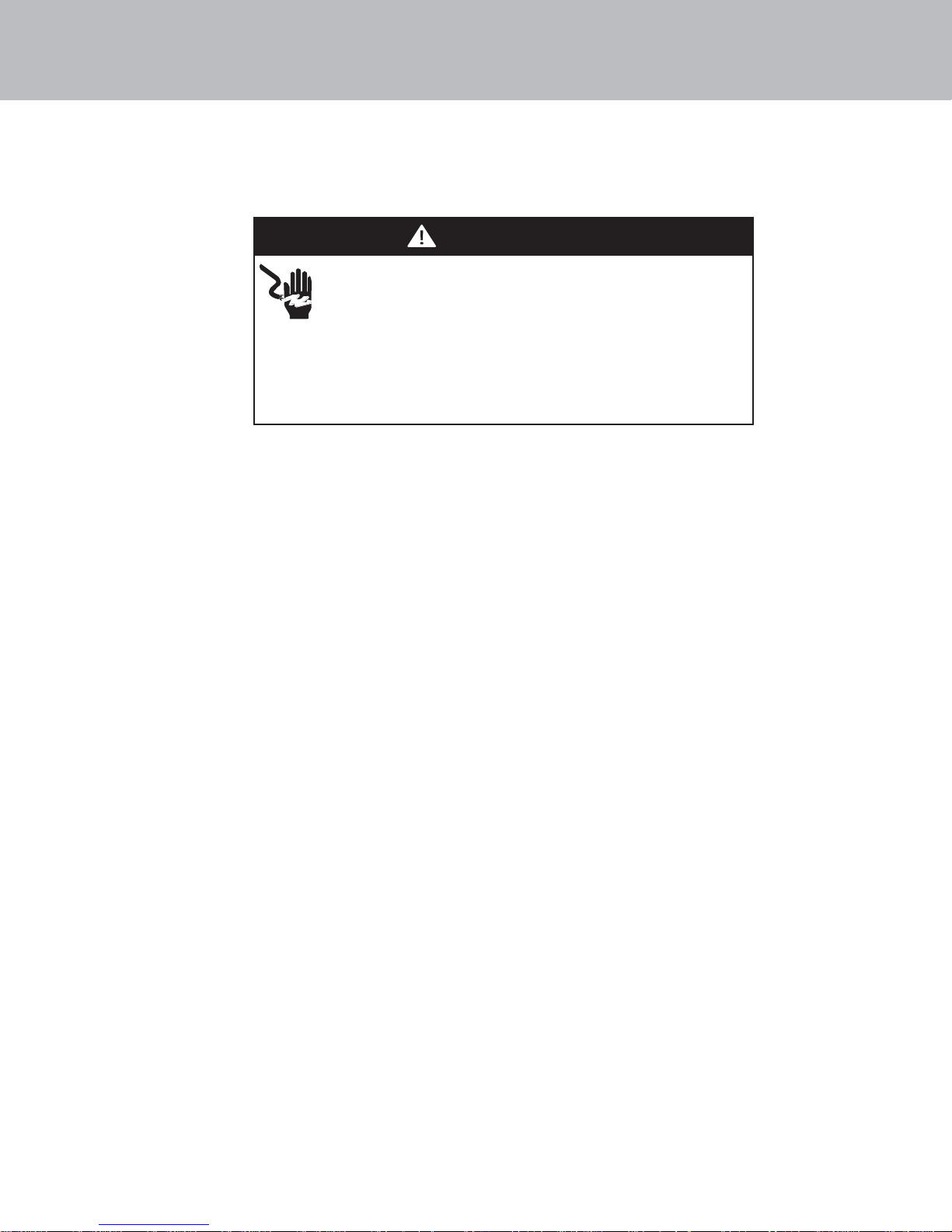
ELECTRICAL SHOCK HAZARD
This appliance is equipped with a 3-prong power
cord with a grounding plug for your protection
against shock hazard and should be plugged
directly into a properly grounded receptacle.
Only use power cord supplied with the unit.
2
Page 3
Dimensions
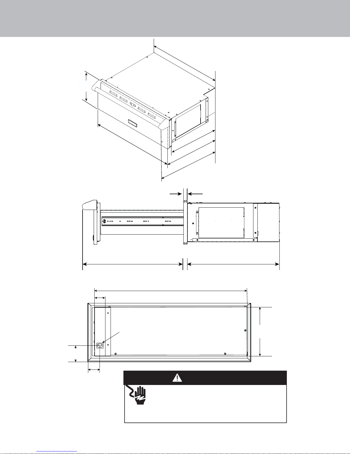
Side View
10-1/4”
(26.0 cm)
VWD527 22-3/4” (57.8 cm)
VWD530 25-3/4” (65.4 cm)
VWD527 26-1/2” (67.3 cm)
VWD530 29-1/2” (74.9 cm)
21-1/4”
(54.0 cm)
22-3/4”
(57.8 cm)
25-1/2”
(64.7 cm)
1-1/2”
(3.8 cm)
Rear View
2” (5.1 cm)
2-1/2”
(6.4 cm)
1-3/4”
(4.4 cm)
25-1/2”
(64.8 cm)
120 VAC Electrical
Connection
VWD527 24-3/4” (62.9 cm)
VWD530 27-3/4” (70.5 cm)
21-1/4”
(54.0 cm)
(22.9 cm)
WARNING
ELECTRICAL SHOCK HAZARD
This appliance is equipped with a 3-prong power cord
with a grounding plug for your protection against shock
hazard and should be plugged directly into a properly grounded
receptacle. Only use power cord supplied with the unit.
9”
3
Page 4
Speci cations
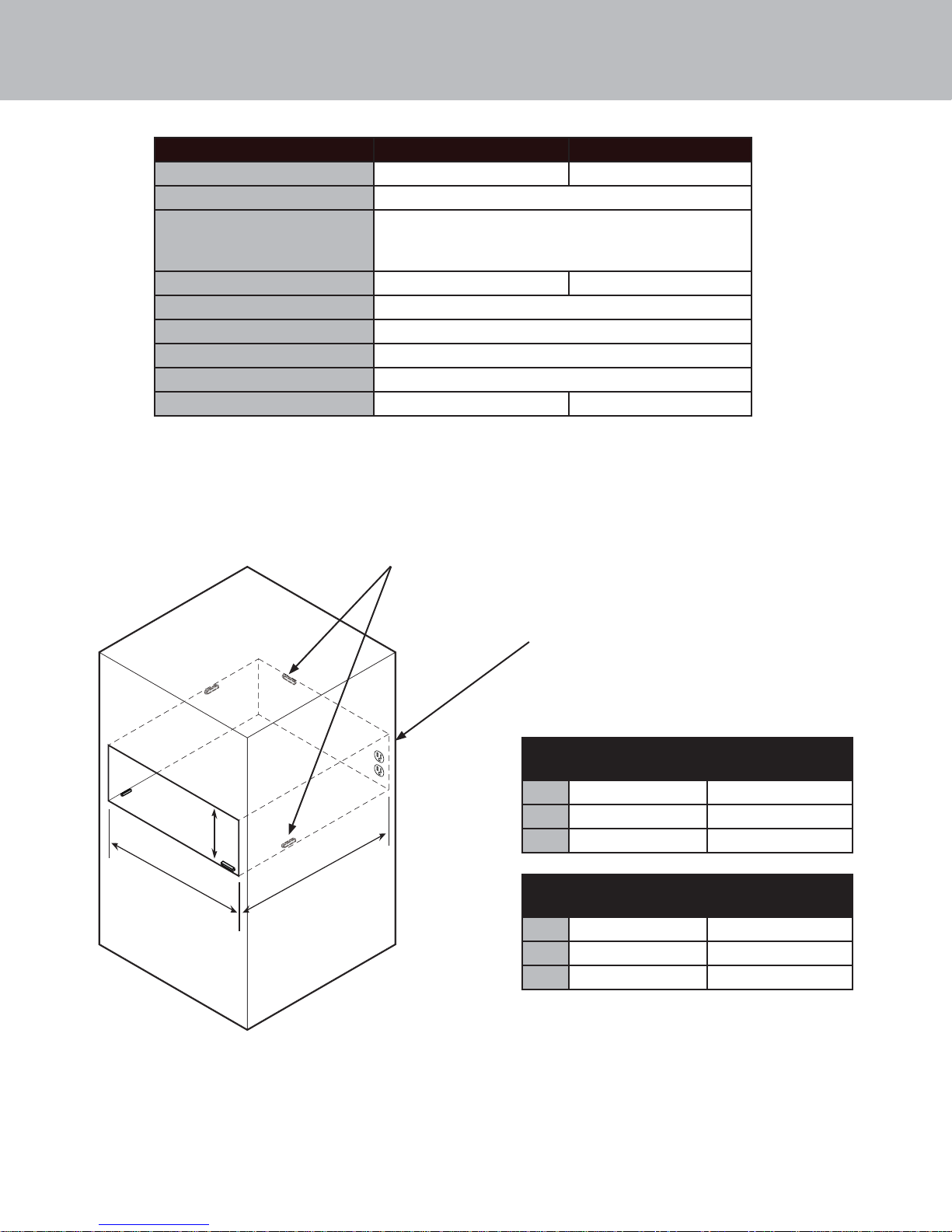
Description VWD527 VWD530
Overall width 26-1/2” (67.3 cm) 29-1/2” (74.9 cm)
Overall height 10-1/4” (26.0 cm)
Overall depth
To end of handle
With drawer fully extended
Interior width 19-1/8” (48.6 cm 22-1/8” (56.1 cm)
Interior height 5-1/2” (14.0 cm)
Interior depth 20-1/4” (51.4 cm)
Electrical requirement 120V/15 amp power cord included with the unit
Max Amp Usage 4.08 Amps
Approx. shipping wt. 80 lb. (36 kg) 90 lb. (40.5 kg.)
Cutout Dimensions
25-1/2” (64.8 cm)
48-1/4” (122.6 cm)
Spacers can be placed anywhere inside
the cutout as needed to make sure
unit is level and does not tilt.
Electrical receptacle can be located any
where on back cutout. Preferred location is
the rear right so that excess cord can lie in
space behind control panel.
DIM Standard Mount
VWD527
A 23-1/2” (59.7 cm) 24-7/8” (63.2 cm)
C
B
A
* When installing in a ush mount application, spacers may be
required to ensure unit remains level and does not tilt forward
when opened. Spacers can be placed on top or bottom - front or
rear of cabinet. Location and size will vary based on installation
and cutout. Outer cabinet edges need to be nished.
B
C 9-1/4” (23.5 cm) 10-1/2” (26.7 cm)
DIM Standard Mount
A 23-1/2” (59.7 cm) 24-7/8” (63.2 cm)
B
C 9-1/4” (23.5 cm) 10-1/2” (26.7 cm)
25-1/4” (64.1 cm) 26-3/4” (67.9 cm)
VWD530
28-1/4” (71.7 cm) 29-3/4” (75.6 cm)
Flush Mount*
VWD527
Flush Mount*
VWD530
4
Page 5
Electrical Requirments
-Check your national and local codes regarding this unit.
-Use 120V/15 amp power cord included with the unit.
Electrical Connection
This appliance is equipped with a 3-prong power cord with
a grounding plug for your protection against shock hazard
and should be plugged directly into a properly grounded
receptacle. Do not cut or remove the grounding prong from
this plug. Unit must be grounded in accordance with local
codes or with the National Electrical Code ANSI/NFPA 70, or the
Canadian Electrical Code, CSA C22.
General Information
WARNING
ELECTRICAL SHOCK HAZARD
• When installing this unit directly below other units, only install with Viking Range, LLC built-in products.
•Remove warming drawer carefully from carton. Remove all loose packaging and accessories.
• It is the responsibility of the installer to comply with local codes. If no local codes are applicable, wire in accordance
with the National Electrical Code, ANSI/NFPA-70 – latest edition.
• Line disconnect switch, circuit breaker, GFI (for outdoor models) or plug/ receptacle of power cord connection should be readily
accessible to the operator.
•Ground unit per applicable electrical codes.
•Any installation not matching the speci cations discussed in these instructions will void the manufacturer’s warranty.
READ AND FOLLOW ALL WARNING AND CAUTION INFORMATION WHEN INSTALLING THIS APPLIANCE.
Moving, Handling and Unpacking
Remove and discard all packing materials, including cardboard and tape on the outside and inside of the warming drawer.
Some stainless steel parts may have a plastic protective wrap which must be peeled o . The interior should be washed thoroughly
with hot, soapy water to remove lm residues and any dust or debris before being used, then rinsed and wiped dry. Solutions
stronger than soap and water are rarely needed.
5
Page 6
Installation
2
1
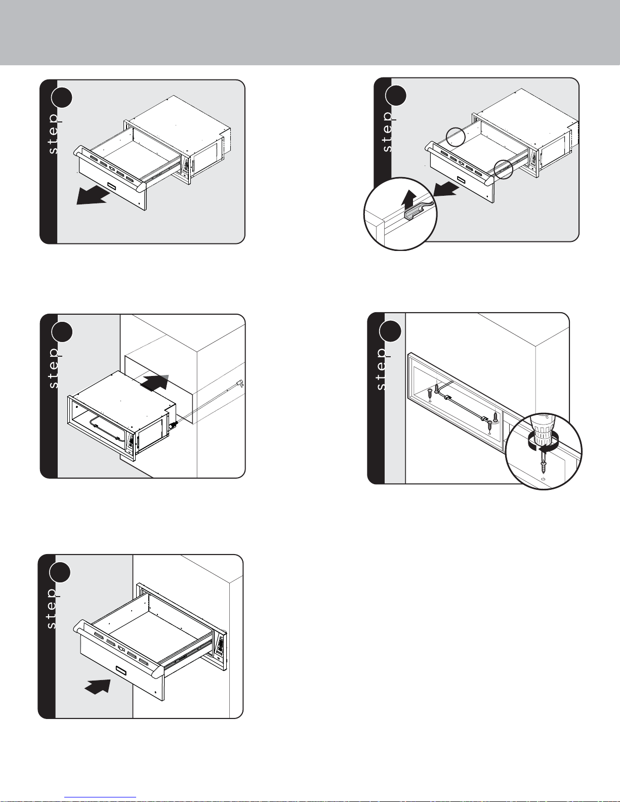
Pull out warming drawer pan until fully extended
3
2
1
Slide nger along right and left side until you reach the
hand latches (located approximately in the center of the
rail). Pull up on on the left side latch and push down
on the right side latch at the same time. Pull out the
drawer pan.
4
Attach cord to the back of the control panel and plug
into receptacle in cutout. Slide warming drawer cavity
into the cabinet opening. To avoid an electrical shock
hazard, make sure you only use the cord provided
with the unit.
5
Replace warming drawer pan assembly.
x4
Secure the warming drawer to the cutout using the
four mounting screws which are provided.
6
Page 7

Final Preparation
All stainless steel body parts should be wiped with hot, soapy water and with a liquid cleaner designed for this material.
If buildup occurs, DO NOT use steel wool, abrasive cloths, cleansers, or powders! If it is necessary to scrape stainless steel
to remove encrusted materials, soak with hot, wet cloths to loosen the material, then use a wool or nylon scraper. DO NOT use a
metal knife, spatula, or any other material tool to scrape stainless steel! Scratches are almost impossible to remove.
Service Information
If service is required, call your authorized service agency.
Have the following information readily available.
• Model number
• Serial number
• Date purchased
• Name of dealer from whom purchased
Clearly describe the problem that you are having. If you are unable to obtain the name of an authorized service agency, or if you
continue to have service problems, contact Viking Range, LLC at1-888-845-4641, or write to:
Viking Range, LLC
PREFERRED SERVICE
111 Front Street
Greenwood, Mississippi 38930 USA
Record the information indicated below. You will need it if service is ever required. The model and serial number for your warming
drawer Rating/Serial plate is located on the left, rear side.
Model no. _________________________________________Serial no. __________________________________________
Date of purchase ___________________________________Date Installed ______________________________________
Dealer’s name ________________________________________________________________________________________
Address _____________________________________________________________________________________________
____________________________________________________________________________________________________
If service requires installation of parts, use only authorized parts to insure protection under the warranty.
7
Page 8

or visit our website at vikingrange.com in the US
062390-000 EN (043017)
Viking Range, LLC
111 Front Street
Greenwood, Mississippi 38930 USA
(662) 455-1200
For product information, call 1-888-845-4641
or brigade.ca in Canada
 Loading...