

Viking Range 30” W, 48” W, 36” W Installation Instructions Manual
INSTALLATION
INSTRUCTIONS
DUAL FUEL RANGES
VIKING RANGE CORPORATION
111 Front Street
Greenwood, Mississippi 38930 USA
(662) 455-1200
IMPORTANT - PLEASE READ AND FOLLOW
•Before beginning, please read these instructions completely and carefully.
•Do not remove permanently affixed labels, warnings, or plates from the product. This may void the warranty.
•Please observe all local and national codes and ordinances.
•Please ensure that this product is properly grounded.
•The installer should leave these instructions with the consumer who should retain for local inspector’s use and for future
reference.
Installation must conform with local codes or in the absence of codes, the National Fuel Gas Code ANSI Z223.1-latest
edition. IN CANADA: Installation must be in accordance with the current CAN/CGA B149.1 & 2 Gas Installation codes
and/or local codes. Electrical installation must be in accordance with the current CSA C22.1 Canadian Electrical Codes
Part 1 and/or local codes.
In Massachusetts: All gas products must be installed by a “Massachusetts” licensed plumber or gasfitter. A “T” type
handle manual valve must be installed in the gas supply line to the appliance.
1. Do not store or use gasoline or other flammable vapors
and liquids in the vicinity of this or any other appliance.
2. WHAT TO DO IF YOU SMELL GAS:
•Do not try to light any appliance.
•Do not touch any electrical switch; do not use any
phone in your building.
•Immediately call your gas supplier from a neighbor’s
phone.
•Follow the gas supplier’s instructions.
•If you cannot reach your gas supplier, call the fire
department.
3. Installation and service must be performed by a
qualified installer, service agency, or the gas supplier.
WARNING
If not installed, operated and maintained in
accordance with the manufacturer’s instructions, this
product could expose you to substances in fuel or
from fuel combustion which can cause death or
serious illness and which are known to cause
cancer, birth defects, or other reproductive harm.
WARNING: IF THE INFORMATION IN
THIS MANUAL IS NOT FOLLOWED
EXACTLY, A FIRE OR EXPLOSION MAY
RESULT CAUSING PROPERTY DAMAGE,
PERSONAL INJURY, OR DEATH.
For example, benzene is a chemical which is
part of the gas supplied to the cooking
product. It is consumed in the flame during
combustion. However exposure to a small
amount of benzene is possible if a gas leak
occurs. Formaldehyde and soot are byproducts of incomplete combustion. Properly
adjusted burners with a bluish rather than
yellow flame will minimize incomplete
combustion.
WARNING!
•This range can tip.
•Injury to persons could result.
•Install anti-tip device packed with range.
•See Installation Instructions
WARNING
Frame grounded to neutral of appliance through a link. If local codes do not permit grounding through the neutral, the
3-conductor cord or cable assembly must be replaced by a 4-conductor cord or cable assembly. See manufacturer’s
instructions.
2
Specifications - Dual Fuel 30”, 36” W. and 48” W. Ranges
Minimum clearances from adjacent combustible construction
•Cooking surface and below (36” [91.4 cm ] and below)
•Sides - 0”
•Rear - 0” with backguard or high shelf; 0” with island trim and non-combustible rear wall; 6” (15.2 cm) with island trim and combustible rear wall.
•Top grate support - 36” (91.4 cm)
•Above cooking surface (above 36” [91.4 cm])
•Sides - 6” (15.2 cm)
•Within 6” (15.2 cm) side clearance, wall cabinets no deeper than 13” (33.0 cm) must be minimum 18” (45.7 cm) above cooking surface.
•Wall cabinets directly above product must be minimum 36” (91.4 cm) above cooking surface
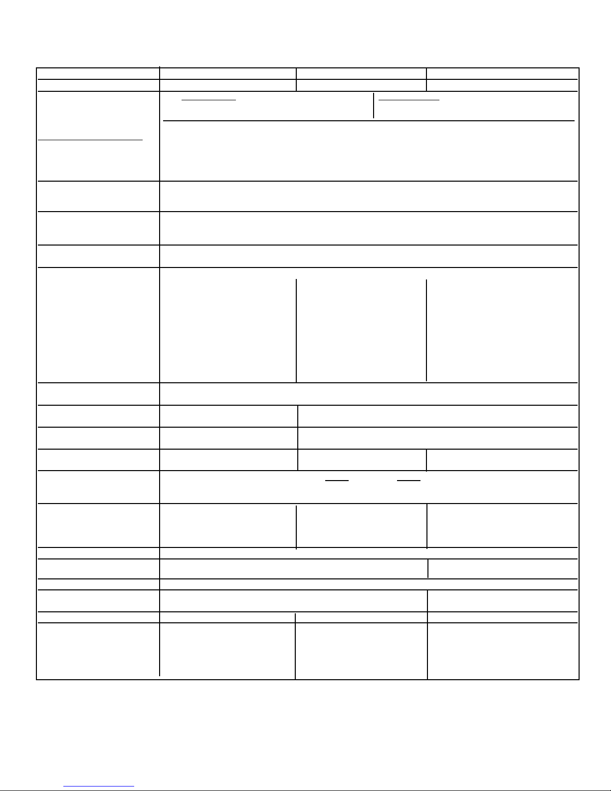
Description 30” W. Models 36” W. Models 48” W. Models
Overall width
29 7/8” (75.9 cm) 35 7/8” (91.1 cm) 47 7/8” (121.6 cm)
Overall height Open Burner Sealed Burner
To top of grate support - Min. 35 7/8” (91.1 cm) To top of burner grate - Min. 37 3/8 “ (94.9 cm)
Max. 37 5/8” (95.6 cm) Max. 39 1/8” (99.4 cm)
Legs adjust 1 3/4” (4.5 cm)
Additions to Base Height
To top of island trim - add 1 1/4” (3.2 cm)
To top of 6” backguard - add 6” (15.2 cm)
To top of 10” backguard - add 10” (25.4 cm)
To top of high shelf - add 23 1/2” (59.7 cm)
Overall depth from rear To end of side panel - 24 5/16” (61.8 cm)
To end of control panel - 26 1/4” (66.7 cm)
To end of knobs - 27 3/4” (70.5 cm)
Electrical requirements 240-208/120 VAC, 60 Hz electrical connection box on product, connect with locally supplied
3-wire, flexible cord or “pigtail” rated 40 amp 125-250 VAC minimum. Cord must be agency
approved for use with household electric ranges.
Gas reguirements Shipped natural gas standard; field convert to LP/Propane with standard convertible regulator;
accepts standard residential 1/2” (1.3 cm) ID gas service line.
Maximum amp usage 240V-6098 watts; 25.4 amps 6B-240V-6634 watts; 27.6 amps 6G- 240V-8914 watts; 37.1 amps
208V-4757 watts; 22.9 amps 208V-5163 watts; 24.8 amps 208V-6994 watts; 33.6 amps
4G-240V-7462 watts; 31.1 amps 6Q- 240V-8050 watts; 33.5 amps
208V-5880 wattts; 28.3 amps 208V-6245 watts; 30.0 amps
4Q-240V-6634 watts; 27.6 amps 4GQ-240V-8914 watts; 37.1 amps
208V-5163 watts; 24.8 amps 208V-6994 watts; 33.6 amps
4G- 240V-8878watts; 37.0 amps
208V-6963 watts; 33.5 amps
4Q- 240V-8050 watts; 33.5 amps
208V-6994 watts; 30.0 amps
4K - 240V-8914 watts; 37.1 amps
208V-6994 watts; 33.6 amps
Surface burner rating 15,000 BTU Nat./ 13,500 BTU LP/Propane
(4.4 kW Nat. / 4.0 kW LP)
Griddle burner rating N/A 15,000 BTU Nat./ 13,500 BTU LP/Propane
(4.4 kW Nat. / 4.0 kW LP)
Grill burner rating
N/A 12” - 1@ 18,000 BTU Nat.(5.3 kW)/16,00 BTU LP/Propane (4.7 kW)
24” - 2@ 15,000 BTU Nat.(4.4 kW)/13,500 BTU LP/Propane (4.0 kW)
Preheat rating 240V - 6000 watts 240V - 6460 watts 240V -6000 watts
208V - 4530 watts 208V - 4850 watts 208V - 4530 watts
Broil rating 240V 208V
Maxi Broil 8 Pass 3000 watts 2250 watts
Mini Broil 4 Pass 1250 watts 940 watts
Bake rating (partial power 240V - 2935 watts 240V - 3440 watts Right - 240V - 2935 watts
from broil element) 208V - 2247 watts 208V - 2620 watts 208V - 2247 watts
Left - 240V - 1932 watts
208V - 1494 watts
Convection cook rating 240V - 2200 watts 208V - 1650 watts
Oven Interior width
23” (58.4 cm) 29” (73.7 cm) Right - 23” (58.4 cm)
Left - 12 1/8” (30.8 cm)
Oven Interior height 16 1/8” (41.0 cm)
Oven Interior depth 15 3/8” (39.1 cm) Right - 15 3/8” (39.1 cm
Left - 17 1/4” (43.8 cm)
Oven Interior overall size 3.3 cu. ft. 4.2 cu. ft. Right - 3.3 cu. ft. Left - 2.1 cu. ft
Approximate Shipping wt. 424 lbs. (190.8 kg) 6B - 465 lb. (209.3 kg) 6G - 624 lb. (280.8 kg)
4Q - 470 lb. (211.5 kg) 6Q - 620 lb. (279.0 kg)
4G - 475 lb. (213.8 kg) 4GQ - 629 lb. (283.1 kg)
4G- 635 lb. (285.8 kg)
4Q- 625 lb. (281.3 kg)

3
GENERAL INFORMATION
1. WARNING: The use of cabinets for storage above the appliance may result in a potential burn hazard.
Combustible items may ignite, metallic items may become hot and cause burns. If a cabinet storage is to be
provided the risk can be reduced by installing a rangehood that projects horizontally a minimum of 5” (12.7 cm)
beyond the bottom of the cabinets.
2. WARNING: This appliance shall not be used for space heating. This information is based on safety considerations.
3. All openings in the wall behind the appliance and in the floor under the appliance shall be sealed.
4. Keep appliance area clear and free from combustible materials, gasoline, and other flammable vapors.
5. Do not obstruct the flow of combustion and ventilation air.
6. Disconnect the electrical supply to the appliance before servicing.
7. When removing oven for cleaning and/or service;
A. Shut off gas at main supply
B. Disconnect AC power supply
C. Disconnect gas line to the inlet pipe.
D. Carefully remove the range by pulling outward. CAUTION: Range is heavy; use care in handling.
8. Electrical Requirement
Listed on Specification sheet. Electrical installation should comply with national and local codes.
9. Gas Manifold Pressure
Natural gas - 5.0” W.C.P.
LP/Propane - 10.0” W.C.P.
10. Flexible Connection
If the unit is to be installed with flexible couplings and/or quick disconnect fittings, the installer must use a flexible
connector approved by national and local codes.
11. The misuse of oven doors (e.g. stepping, sitting, or leaning on them) can result in potential hazards and/or injuries.
WARNING!!
ELECTRICAL GROUNDING INSTRUCTIONS
This appliance must be electrically grounded in accordance with local codes or, in the absence of codes, with the
National Electrical Code, ANSI/NFPA 70-latest edition. Installation should be made by a licensed electrician.
FOR PERSONAL SAFETY, THIS APPLIANCE MUST BE PROPERLY GROUNDED
Burner Caps
1. Burner caps are packed in styrofoam top pack with the grates and burner bowls.
2. Remove grates. Remove burner cap and place one on top of burners. Place grate on grate support.
Legs
1. Legs are packed in styrofoam top pack.
2. Legs should be installed near to where the appliance is to be used, as they are not secure for long transit. After
unpacking the range, raise it about a foot to remove the bottom shipping skid. Keep the unit raised to permit the legs
to be screwed into our couplings and lower it gently to keep any undue strain from the legs and internal mounting
hardware. It is strongly recommended that a pallet or lift jack be used rather than tilting.
Back Trim Accessories
Assembly and installation instructions are included with all back trim accessories.
4
Important: Leveling/Adjustments/Alignment
Closely follow the procedures below to ensure proper performance and appearance of the range.
1. If the floor is smooth and level, level the unit with the
screw thread of the legs. Set the high corner of the
range so that the the top of the side trim is 3/8” (.95cm)
above the countertop, and level the range to the high
corner.
2. If the floor is uneven or has a decided slope, level the
unit with metal shims, as the adjustment required may
exceed the thread available in the leg.
3. After the range is properly leveled, the drip tray handle
may be aligned by loosening the screws and adjusting
the handle horizontally within the limits provided by the
slotted screw holes.
4. Alevel should be placed across the top of the range and
the unit leveled both front-to-back and side-to-side. If it
is not level, burner combustion may be erratic, liquid, or
semi-liquid batters will cook at an angle, and the unit
may not function efficiently.
A. Right Side
Front / Back
Adjustable Legs
B. Left Side
Front / Back
Adjustable Legs
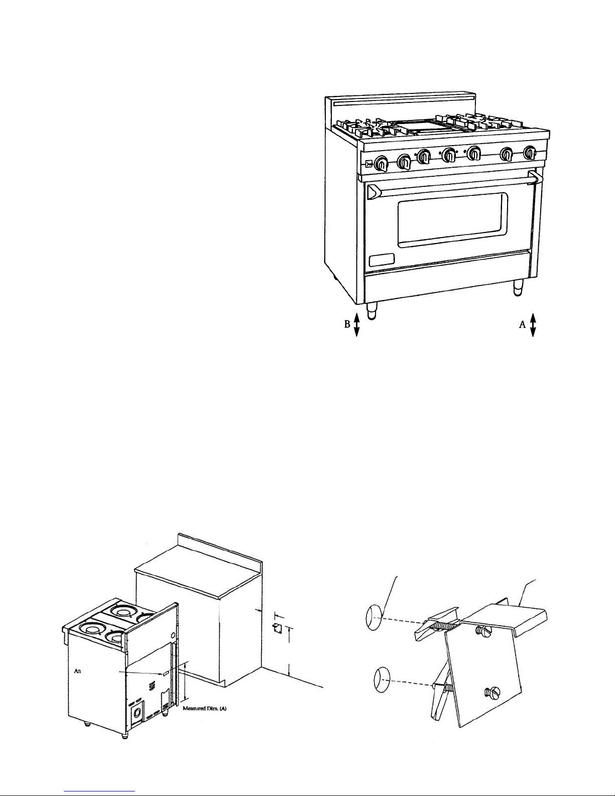
Stability Device Installation Instructions
1. The anti-tip bracket is to be attached to the rear wall as shown. The dimension for the bracket location from the floor
is to be determined after the range legs have been adjsuted to the proper installation height shown in the installation
instructions and the range has been leveled.
2. Measure from the floor to the bottom of the anit-tip opening located on the back of the range.
3. Locate the anti-tip bracket on the wall with the top left corner at the measured dimension (A) plus 1/2” (1.3 cm) from
the floor and 5 5/8” (14.3 cm) from where the left side of the range (facing range) is to be located.
4. Slide range into place. Be sure the anit-tip bracket slides into the anit-tip opening.
Anti-tip
Opening
5 5/8”
(14.3 cm)
Measured Dim. (A)
+ 1/2” (1.3 cm)
Mounting Holes
Anti-tip
Bracket
5
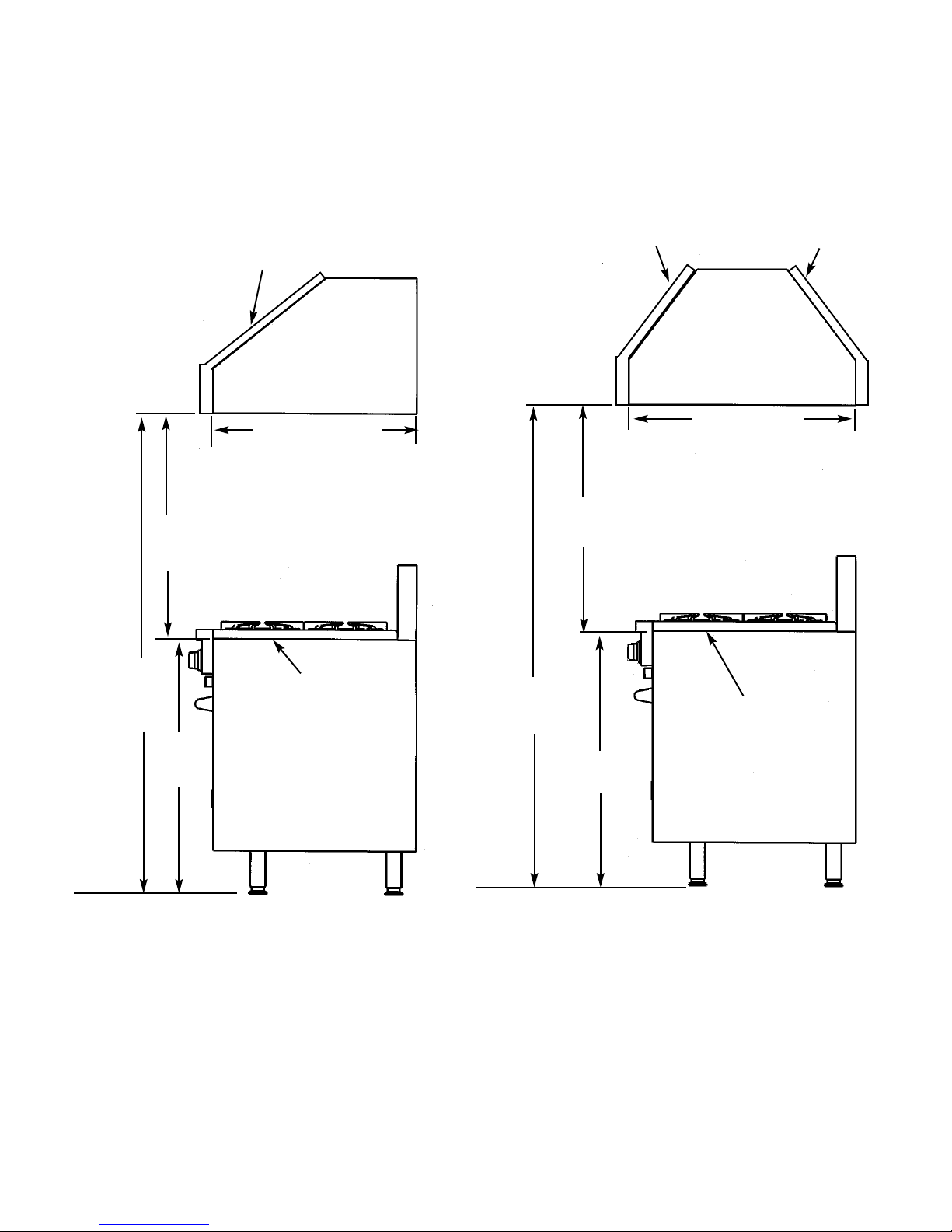
WOOD/COMPOSITE OVERLAY INSTALLATION
The bottom of a standard hood should be 30” (76.2 cm) min to 36” (91.4 cm) max. above the countertop. This
would typically result in the bottom of the hood being 66” (167.6 cm) to 72” (182.9 cm) above the floor. Refer to the
rangehood installation instructions for additional information. These dimensions provide for safe and efficient operation
of the hood.
30” (76.2 cm) min
36” (91.4 cm) max
66” - 72”
(167.6 cm -
182.9 cm)
30” (76.2 cm) min
36” (91.4 cm) max
66” - 72”
(167.6 cm -
182.9 cm)
36”
(91.4 cm)
ISLAND INSTALLATION
WALL INSTALLATION
36”
(91.4 cm)
Metal Hood
Metal Hood
Wood/Composite Overlay
Wood/Composite Overlay
Countertop
Countertop
24” (61.0 cm)
or
27” (38.6 cm)
30” (76.2 cm)
6
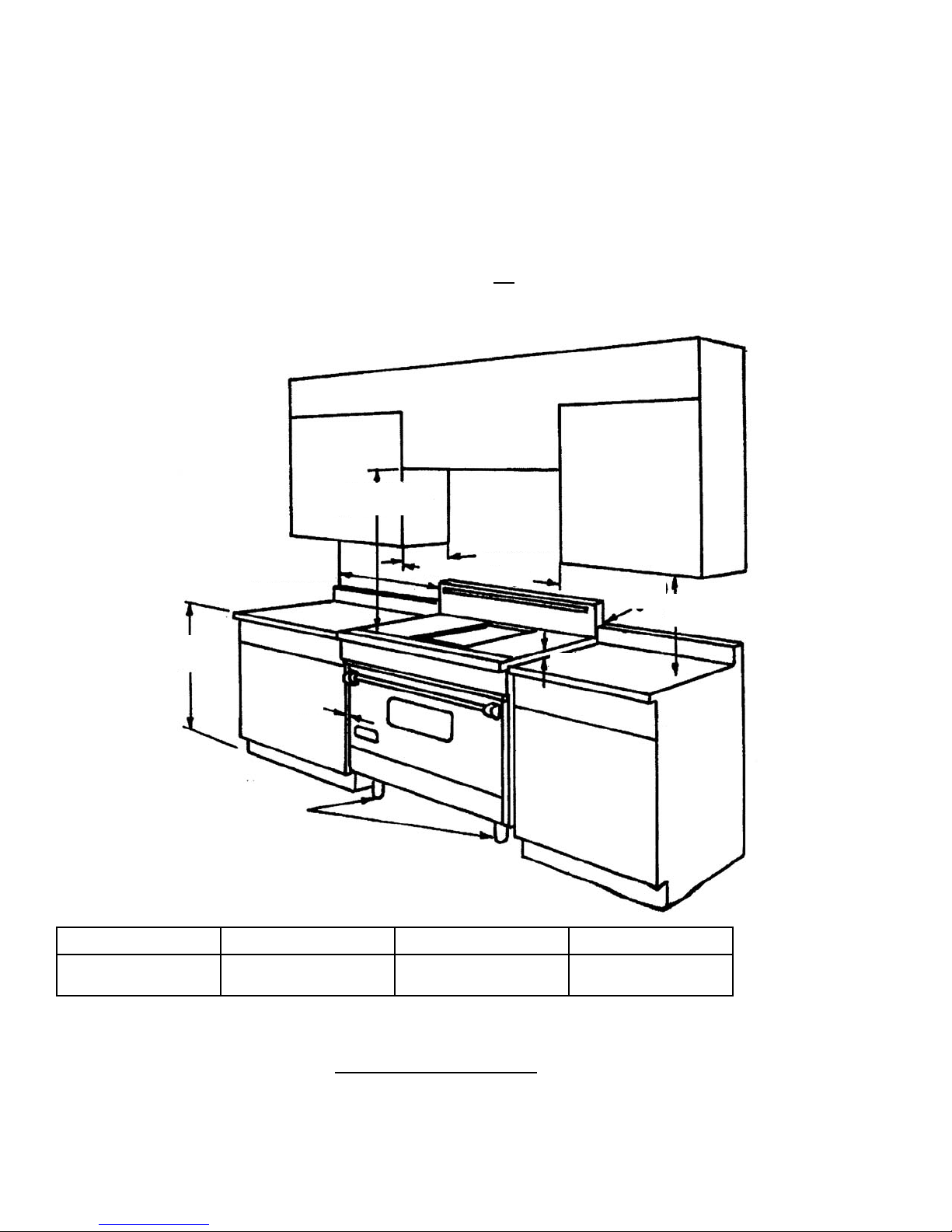
Proximity to Side Cabinet Installation
1. This range may be installed directly adjacent to existing 36” (91.4 cm) high base cabinets. IMPORTANT: The side
trim MUST be 3/8” (.95 cm) above the adjacent base cabinet countertop. This may be accomplished by raising the
unit using the adjustment spindles on the legs.
2. The range CANNOT be installed directly adjacent to sidewalls, tall cabinets, tall appliances, or other side vertical
surfaces above 36” (91.4 cm) high. There must be a minimum of 6” (15.2 cm) side clearance from the range to such
combustible surfaces above the 36” (91.4 cm) counter height.
3. Within the 6” (15.2 cm) side clearance to combustible vertical surfaces above 36” (91.4 cm) , the maximum wall
cabinet depth must be 13” (33.0 cm) and wall cabinets within this 6” (15.2 cm) side clearance must be 18” (45.7 cm)
above the 36” (91.4 cm) high countertop.
4. Wall cabinets above the range must be a minimum of 42” (106.7 cm) above the range cooking surface for the full
width of the range. This minimum height requirement does not
apply if a rangehood is installed over the cooking
surface.
*Overall Width
30” W. Models
29 7/8” (75.9 cm)
36” W. Models
35 7/8” (91.1 cm)
48” W. Models
47 7/8” (121.6 cm)
Electrical Requirements
Check your national and local codes regarding this unit. This range requires 3 wires, 240-208/120 VAC/60 Hz. See
next section for grounding instructions. It should be fused separately. CAUTION: Be sure the electrical power is off
from the breaker box to the junction box until the range is installed and ready to operate. The junction box should be
located as shown in the drawing and connected to a suitable ground.
Width of Range
42” Minimum
(106.7 cm)
13” Minimum
(33.0 cm)
6” Minimum
(15.2 cm)
0” (0.0 cm)
0”
(0.0 cm)
18” Minimum
(45.7 cm)
3/8” (.95 cm)
36”
(91.4 cm)
Adjustment
Spindles
 Loading...