

Viking pump H224A-CHC1, 224A-CHC2 Series, HL224A-CHC2, K224A-CHC1, K224A-CHC2 Technical & Service Manual
...
VISIT VIKINGPUMP.COM FOR PDF OF CURRENT TSM ISSUE & TO VIEW REPAIR VIDEOS
TECHNICAL SERVICE MANUAL
INSTALLATION, OPERATION & MAINTENANCE
CHOCOLATE PUMP: CAST IRON
SERIES: 224A-CHC1, 224A-CHC2
SIZES: H, HL, K, KK, LQ, LL, LS, Q, QS
TABLE OF CONTENTS
Model Number Chart ..................................................................1
Introduction ................................................................................1
Safety Information & Instructions ............................................... 2
Special Information ....................................................................3
Rotation ..................................................................................3
Circulation Lines ..................................................................... 3
Jacketed Ports ........................................................................ 3
EC1935 Certication ..............................................................3
Maintenance ...............................................................................3
Lubrication .............................................................................. 3
Cleaning Pump ....................................................................... 3
Storage ................................................................................... 3
Suggested Repair Tools ......................................................... 3
Removal: O-Ring Seal Bushing ................................................. 5
Installation: O-Ring Seal Bushing .............................................. 5
Pump Disassembly ....................................................................6
Pump Assembly .........................................................................7
Thrust Bearing Adjustment ........................................................ 8
Installation: Hardened Iron Idler Bushing ..................................9
Spacer Coupling Lengths ..........................................................9
APPENDIX (Formerly TSM 000) ........................................................9
General Installation Notes ..........................................................9
Foundation ............................................................................... 11
Component & Unit Lifting Features ......................................... 11
Alignment .................................................................................12
Piping .......................................................................................13
Start Up ....................................................................................14
Troubleshooting .......................................................................14
Vacuum Gauge - Suction Port .............................................14
Pressure Gauge - Discharge Port ........................................ 15
Rapid Wear .............................................................................16
Preventative Maintenance .......................................................16
Do’s & Don’ts ...........................................................................17
Operation .............................................................................. 17
Maintenance ......................................................................... 17
Declaration of Conformity ........................................................18
TSM 1462
Page 1 of 18
Issue A
MODEL NUMBER CHART
JACKETED O-RING SEAL BUSHING
GROOVED CASING STANDARD CASING
H224A-CHC1 H224A-CHC2
HL224A-CHC1 HL224A-CHC2
K224A-CHC1 K224A-CHC2
KK224A-CHC1 KK224A-CHC2
LQ224A-CHC1 LQ224A-CHC2
LL224A-CHC1 LL224A-CHC2
LS224A-CHC1 LS224A-CHC2
Q224A-CHC1 Q224A-CHC2
QS224A-CHC1 QS224A-CHC2
INTRODUCTION
The illustrations used in this manual are for identication
purposes only and cannot be used for ordering parts.
Obtain a parts list from a Viking Pump representative. Always
give a complete name of part, part number and material with
the model number and serial number of pump when ordering
repair parts. The unmounted pump or pump unit model
number and serial number are on the nameplate. This manual
only applies to the pump models specied in the "Model
Number Chart" on page 1. Pump specications and
recommendations are listed in AD-23, which is available at
vikingpump.com.
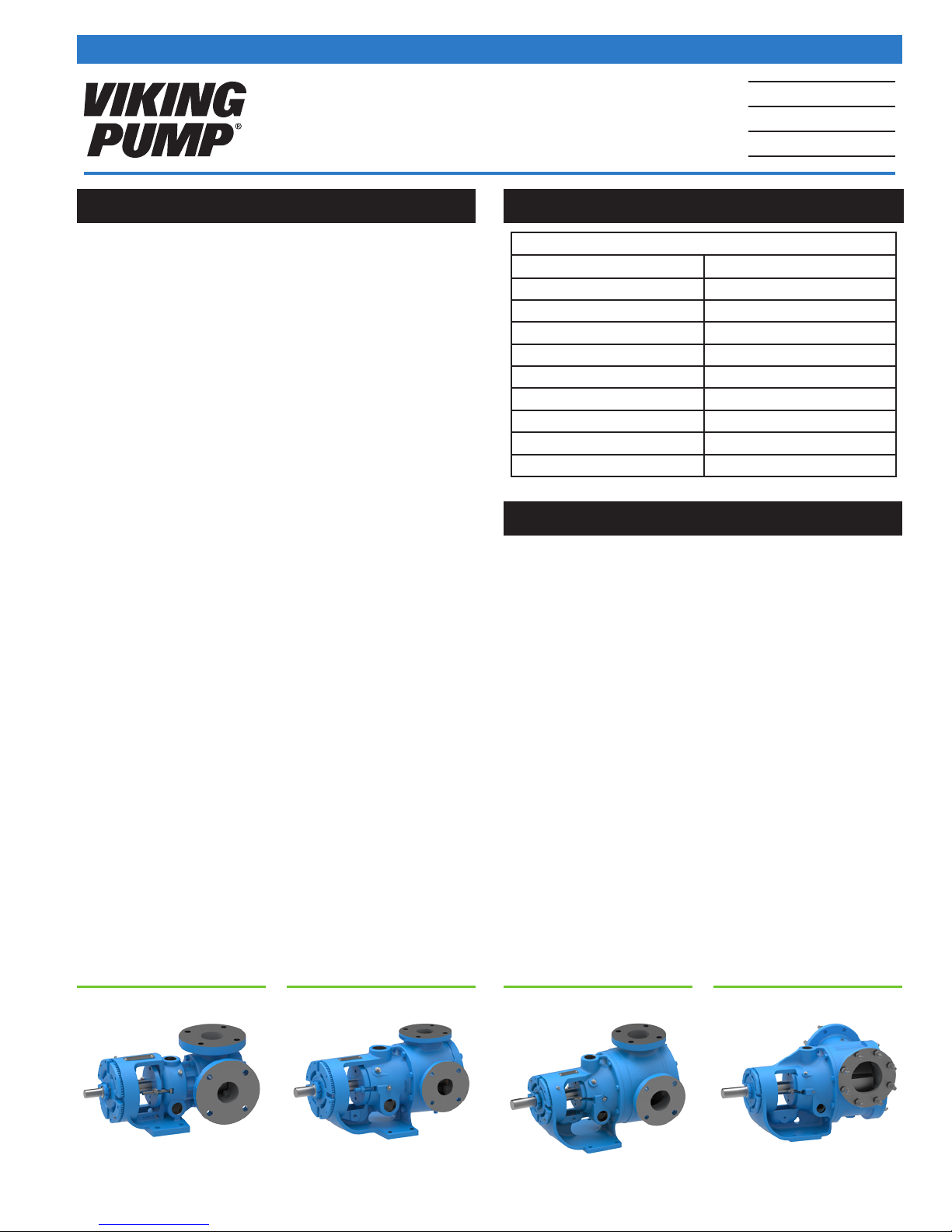
Viking Pump® 224A-CHC1 & 224A-CHC2 Pump Series
designed specically for handling chocolate and related
confectionary processes. Viking Chocolate Series Pumps
are suitable for low hazard foods like chocolate according to
each facility’s HACCP plan. They are not a hygienic design
according to 3A or FDA, and are not suitable for services
requiring CIP or COP.
FIGURE 1: HL FIGURE 3: LSFIGURE 2: K FIGURE 4: QS
Viking Pump, Inc. • A Unit of IDEX Corporation • Cedar Falls, IA ©2018

SAFETY INFORMATION & INSTRUCTIONS
IMPROPER INSTALLATION, OPERATION OR MAINTENANCE
OF PUMP MAY CAUSE SERIOUS INJURY OR DEATH AND/OR
RESULT IN DAMAGE TO PUMP AND/OR OTHER EQUIPMENT.
VIKING’S WARRANTY DOES NOT COVER FAILURE DUE TO
IMPROPER INSTALLATION, OPERATION OR MAINTENANCE.
THE FOLLOWING SAFETY INSTRUCTIONS MUST BE FOLLOWED AND ADHERED TO AT ALL TIMES.
DANGER = FAILURE TO FOLLOW THE INDICATED
⚠
INSTRUCTION MAY RESULT IN SERIOUS INJURY
OR DEATH.
⚠
DANGER
BEFORE opening any liquid chamber (pumping chamber,
reservoir, relief valve adjusting cap tting, etc.) be sure that:
• Any pressure in the chamber has been completely vented
through the suction or discharge lines or other appropriate
openings or connections.
• The pump drive system means (motor, turbine, engine,
etc.) has been “locked out” or otherwise been made nonoperational so that it cannot be started while work is being
done on the pump.
• You know what material the pump has been handling,
have obtained a material safety data sheet (MSDS) for
the material, and understand and follow all precautions
appropriate for the safe handling of the material.
THIS INFORMATION MUST BE FULLY READ BEFORE
BEGINNING INSTALLATION, OPERATION OR MAINTENANCE
OF PUMP AND MUST BE KEPT WITH PUMP. PUMP MUST BE
INSTALLED, OPERATED AND MAINTAINED ONLY BY SUITABLY
TRAINED AND QUALIFIED PERSONS.
WARNING = IN ADDITION TO SERIOUS INJURY OR DEATH,
⚠
FAILURE TO FOLLOW THE INDICATED INSTRUCTION MAY
CAUSE DAMAGE TO PUMP AND/OR OTHER EQUIPMENT
⚠
WARNING
INSTALL pressure gauges/sensors next to the pump suction
and discharge connections to monitor pressures.
⚠
WARNING
USE extreme caution when lifting the pump. Suitable lifting
devices should be used when appropriate. Lifting eyes
installed on the pump must be used only to lift the pump, not
the pump with drive and/or base plate. If the pump is mounted
on a base plate, the base plate must be used for all lifting
purposes. If slings are used for lifting, they must be safely and
securely attached. For weight of the pump alone (which does
not include the drive and/or base plate) refer to the Viking
Pump product catalog.
⚠
DANGER
BEFORE operating the pump, be sure all drive guards are in
place.
⚠
DANGER
DO NOT operate pump if the suction or discharge piping is
not connected.
⚠
DANGER
DO NOT place ngers into the pumping chamber or its
connection ports or into any part of the drive train if there is
any possibility of the pump shafts being rotated.
⚠
WARNING
DO NOT exceed the pumps rated pressure, speed, and
temperature, or change the system/duty parameters from
those the pump was originally supplied, without conrming its
suitability for the new service.
⚠
WARNING
BEFORE operating the pump, be sure that:
• It is clean and free from debris
• All valves in the suction and discharge pipelines are fully
opened.
• All piping connected to the pump is fully supported and
correctly aligned with the pump.
• Pump rotation is correct for the desired direction of ow.
⚠
DANGER
DO NOT attempt to dismantle a pressure relief valve that has
not had the spring pressure relieved or is mounted on a pump
that is operating.
⚠
DANGER
AVOID contact with hot areas of the pump and/or drive.
Certain operating conditions, temperature control devices
(jackets, heat-tracing, etc.), improper installation, improper
operation, and improper maintenance can all cause high
temperatures on the pump and/or drive.
⚠
WARNING
THE PUMP must be provided with pressure protection. This
may be provided through a relief valve mounted directly on
the pump, an in-line pressure relief valve, a torque limiting
device, or a rupture disk. If pump rotation may be reversed
during operation, pressure protection must be provided on
both sides of pump. Relief valve adjusting screw caps must
always point towards suction side of the pump. If pump
rotation is reversed, position of the relief valve must be
changed. Pressure relief valves cannot be used to control
pump ow or regulate discharge pressure. For additional
information, refer to Appendix, General Installation Notes,
item 5 on Pressure Protection or contact your Viking Pump
representative for Engineering Service Bulletin ESB-31.
⚠
WARNING
THE PUMP must be installed in a manner that allows safe
access for routine maintenance and for inspection during
operation to check for leakage and monitor pump operation.
TSM 1462 | Issue A | Page 2 of 18
Viking Pump, Inc. • A Unit of IDEX Corporation • Cedar Falls, IA ©2018

SPECIAL INFORMATION
MAINTENANCE
ROTATION
Viking pumps operate equally well in a clockwise or
counter-clockwise rotation. Some constructions may require
modications, consult Viking Pump representative if unsure.
Shaft rotation determines which port is suction and which is
discharge. Suction port is where pumping elements (gear
teeth) come out of mesh.
If pump rotation is reversed during operation, pressure
protection must be provided on both sides of pump.
Relief valve adjusting screw cap must always point towards
suction side of pump. If pump rotation is reversed, remove
pressure relief valve and turn end for end.
CIRCULATION LINES
This equipment (not utilized on all pumps) must be connected
properly. Packed pumps typically have a ush line from
packing chamber to discharge port. Mechanical seal
pumps typically have a suckback line from seal chamber to
suction port. If pump rotation is reversed, be sure circulation
connections are connected to the suction or discharge port as
noted above to avoid excessive leakage or damage to pump.
If pump is handling heated product, be sure circulation line is
insulated to assure continued ow.
JACKETED PORTS
Jackets are utilized to heat (or cool) the pump and liquid in the
pump prior to startup. Not all pumps have ports for jacketing.
Jacketing port locations vary by model.
EC1935 CERTIFICATION
EC1935/2004 is a European standard covering
materials that come into contact with foods.
It requires that food contact materials may not
transfer substances to foods in quantities which represent a
health risk to people, lead to an unacceptable change in the
composition of the food, or adversely aect the organoleptic
properties of the food. Viking 224A-CHC1 and -CHC2 pumps
comply with this standard, and the EC1935 cup and fork logo
is visible on the pump nameplate.
See back page for Declaration of Conformity.
These pumps are designed for long, trouble-free service life
under a wide variety of application conditions with a minimum
of maintenance. The points listed below will help provide long
service life.
LUBRICATION
External lubrication must be applied slowly with a hand gun
to the bearing houseing lubrication tting every 500 hours
of operation with food grade grease, NLGI # 2. Contact your
Viking Pump representative with specic lubrication questions
or to obtain a copy of Engineering Service Bulletin ESB-515.
The O-Ring Seal Bushing used in the 224A-CHC1 &
224A-CHC2 pumps require external food grade grease
lubrication applied slowly with a grease gun every two weeks
of operation. Approximate grease capacity is 1.5 oz. on H-LS
and 3 oz. on the Q and QS.
CLEANING PUMP
Keep pump as clean as possible. This will facilitate inspection,
adjustment and repair work and help prevent overlooking a
dirt covered grease tting.
STORAGE
If pump is to be stored, or not used for six months or more,
pump must be drained and a light coat of non-detergent light
food grade oil must be applied to all internal pump parts.
Lubricate ttings and apply food grade grease to pump shaft
extension. Viking suggests rotating pump shaft by hand one
complete revolution every 30 days to circulate the oil. Tighten
all pump assembly bolts before putting pump in service after
being stored.
SUGGESTED REPAIR TOOLS
The following tools must be available to properly repair these
pumps. These tools are in addition to standard mechanics’ tools
such as open-end wrenches, pliers, screwdrivers, etc. Most of
the items can be obtained from an industrial supply house.
1. Soft Headed hammer
2. Allen wrenches (some mechanical seals and set collars)
3. O-Ring seal bushing installation sleeve
2-751-002-730 for 1.125 inch seal; H-HL pumps
2-751-003-730 for 1.4375 inch seal; K-LL pumps
2-751-005-630 for 2.4375 inch seal; Q-QS pumps
No sleeve needed for LS pumps
4. Bearing locknut spanner wrench
Source: #471 J. H. Williams & Co. or equal; H-LL pumps
Source: #472 J. H. Williams & Co. or equal; LS-QS pumps
5. Spanner wrench, adjustable pin type for use on bearing
housing
Source: #482 J. H. Williams & Co. or equal; H-QS pumps
Supplied with pump; N-RS pumps
6. Brass or hardwood bar
7. Arbor press
Viking Pump, Inc. • A Unit of IDEX Corporation • Cedar Falls, IA ©2018
TSM 1462 | Issue A | Page 3 of 18
Contact your Viking stocking distributor for available seal and rebuild kits
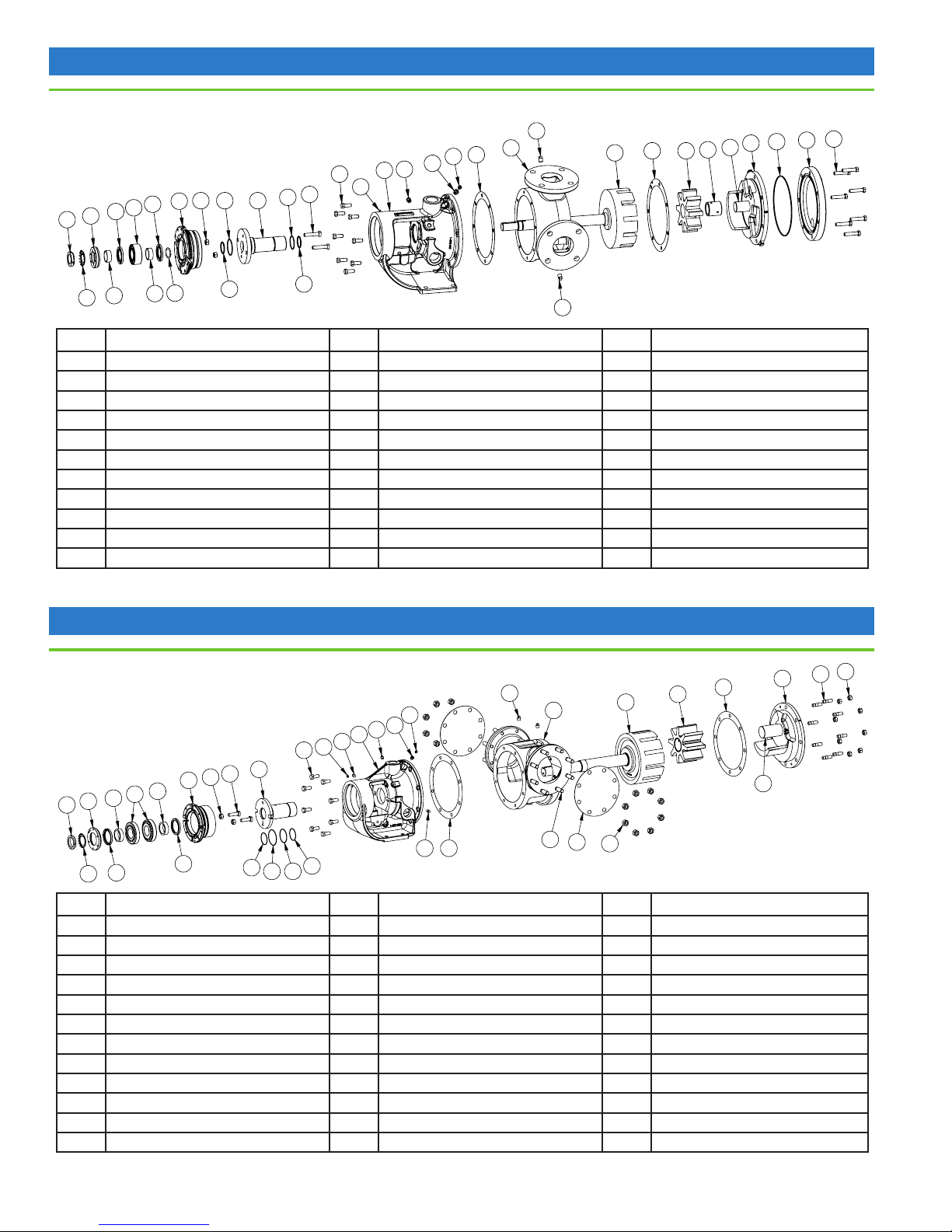
FIGURE 5: EXPLODED VIEW (H, HL, K, KK, LQ, LL, LS SIZES)
30
31
29
26
26A
12B
27
28
17
16
18B
7
6
5
3
1
18C
19
12
35 37
36
38
41
40
39
43
42
8511
4
2
18A
18A
30
ITEM NAME OF PART ITEM NAME OF PART ITEM NAME OF PART
1 Locknut 16 O-Ring Seal Bushing Nut 30 Pipe Plug
2 Lockwasher 17 O-Ring Seal Bushing Capscrew 31 Casing
3 End Cap for Bearing Housing 18A Dynamic O-Ring 35 Head Gasket
4 Bearing Spacer Collar (Outer) 18B Inner Static O-Ring 36 Rotor and Shaft Assembly
5 Lip Seal for Bearing Housing 18C Outer Static O-Ring 37 Idler and Bushing Assembly
6 Ball Bearing 19 O-Ring Seal Bushing 38 Bushing (part of 37)
7 Bearing Housing 26 Pressure Relief Fitting 39 Idler Pin (part of 40)
8 Bearing Spacer Collar (Inner) 26A Reducer Bushing (Not H, HL) 40 Head and Idler Pin Assembly
11 Half Round Ring (Not H, HL) 27 Bracket 41 Jacketed Head Plate Gasket
12 Grease Fitting 28 Capscrew for Bracket 42 Jacketed Head Plate
12B Grease Fitting 29 Bracket Gasket 43 Head Capscrews
Contact your Viking stocking distributor for available seal and rebuild kits
FIGURE 6: EXPLODED VIEW (Q, QS SIZES)
30
26
26A
12B
27
30A
12
28
19
17
16
7
8
6
4
3
1
31
36
35
37
40
39
44
43
5
2
5
18A
18C
18B
18A
ITEM NAME OF PART ITEM NAME OF PART ITEM NAME OF PART
1 Locknut 18A Dynamic O-Ring 34 Pipe Flange Gasket
2 Lockwasher 18B Inner Static O-Ring 35 Head Gasket
3 End Cap for Bearing Housing 18C Outer Static O-Ring 36 Rotor and Shaft Assembly
4 Bearing Spacer Collar (Outer) 19 O-Ring Seal Bushing 37 Idler and Bushing Assembly
5 Lip Seal for Bearing Housing 26 Pressure Relief Fitting 39 Idler Pin (part of 40)
6 Ball Bearing 26A Reducer Bushing 40 Head and Idler Pin Assembly
7 Bearing Housing 27 Bracket 41 Jacketed Head Plate Gasket (not shown)
8 Bearing Spacer Collar (Inner) 28 Capscrew for Bracket 42 Jacketed Head Plate (not shown)
12 Grease Fitting 29 Bracket Gasket 43 Head Capscrews
12B Grease Fitting 30 Pipe Plug 44 Nut for Head
16 O-Ring Seal Bushing Nut 30A Pipe Plug 51 Stud for Flanges
17 O-Ring Seal Bushing Capscrew 31 Casing 52 Nut for Flanges
TSM 1462 | Issue A | Page 4 of 18
51
34
30A
29
52
Viking Pump, Inc. • A Unit of IDEX Corporation • Cedar Falls, IA ©2018

⚠
DANGER !
Before opening any Viking pump liquid chamber
(pumping chamber, reservoir, relief valve adjusting cap
tting, etc.) Be sure:
1. That any pressure in the chamber has been
completely vented through the suction or discharge
lines or other appropriate openings or connections.
2. That the driving means (motor, turbine, engine, etc.)
has been “locked out” or made non-operational so that
it cannot be started while work is being done on pump.
3. That you know what liquid the pump has been handling
and the precautions necessary to safely handle the
liquid. Obtain a material safety data sheet (MSDS) for
the liquid to be sure these precautions are understood.
Failure to follow above listed precautionary measures
may result in serious injury or death.
3. Remove the pair of half round rings (K, KK, L, LQ, LL, and
LS sizes only) under the inner spacer collar from the shaft.
4. Loosen the gland nuts securing the O-Ring Seal Bushing
into the bracket and remove the T-bolts.
5. Thread the jack bolts into the tapped holes at the 6 and 12
o’clock position on the face of the O-Ring Seal Bushing.
Remove the OSB through the bearing housing opening.
6. Clean as much old grease and product out of the area
between the pump bracket bore and shaft as possible,
taking care not to nick the finished surfaces.
If the pump is to be disassembled further, refer to "Pump
Disassembly" on page 6.
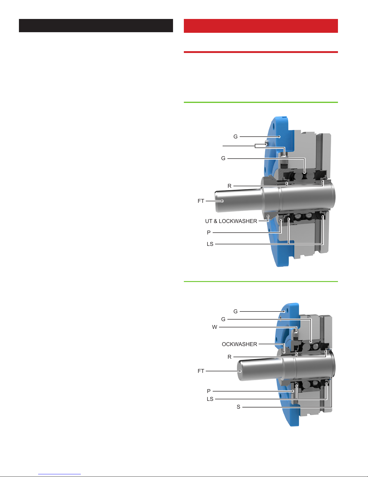
INSTALLATION: O-RING SEAL
BUSHING
FIGURE 7:
Tapered Installation Sleeve
NOTE: Coat rotor shaft, tapered installation
sleeve and inner diameter of O-ring seal bushing
with P-80® or equivalent before assembly.
Shaft
FIGURE 8:
REMOVAL: O-RING SEAL
BUSHING
The O-Ring Seal Bushing (OSB) was specially designed to
that it could be removed and the food grade O-Rings replaced
with minimal pump disassembly.
1. Insert length of hardwood or brass through port opening
between rotor teeth to keep shaft from turning. Bend up
tang of lockwasher and with a spanner wrench, remove
locknut and lockwasher from shaft.
2. Loosen two set screws in the face of the bearing housing
and remove the bearing housing assembly from the
bracket. In order to remove the bearing housing and
O-Ring Seal Bushing with the pump in place, Viking
recommends using Spacer Couplings with at least a 4.75”
gap for the H/HL size pumps, 6.25” gap for the K-LL size
pumps, and a 7.75” gap for the Q/QS size pumps.
1. Lubricate the O-Rings and OSB thoroughly with food
grade O-Ring lubricant or grease.
2. Install the inner dynamic O-Rings and the outer static
O-Rings in the O-Ring grooves in the OSB.
3. Leaving the Rotor Shaft out of the pump, install the O-Ring
Seal Bushing into the bracket. Make sure the gland dimple
is downward. This positions the lubrication groove at the
opposite end in the 6 o’clock position.
4. You will encounter resistance as the first outer static
O-Ring enters the bushing bore area in the bracket. Rotate
the OSB as needed, but do not hammer it or damage to
the O-Rings may occur.
5. Once the OSB is far enough into the bracket bore, you can
use the gland bolts to gently pull the OSB the rest of the
way into the bracket bore.
6. Tighten both nuts on the gland bolts completely.
7. NOTE: Burrs left on the shaft can damage the inner
dynamic O-Rings in the O-Ring Seal Bushing during
installation. Inspect the shaft for burrs and remove any
found with a fine grade of emery cloth.
8. Place tapered seal installation sleeve on shaft (H, HL, K,
KK, LQ, LL, Q, and QS, no sleeve required for LS size).
Coat the rotor shaft & installation sleeve with a generous
amount of food grade grease.
9. Carefully insert the rotor shaft into the pump casing.
Prevent the shaft keyway or threads from contacting the
inner dynamic O-Rings. The shaft threads and keyway
may be taped to ensure the O-Rings aren’t nicked by the
shaft edges.
10. Remove the seal installation sleeve.
11. Reinstall the head with idler gear, using a new head
gasket. Ensure that the crescent is opposite the sealing
area between the ports.
12. Place pair of half round rings in groove on shaft (K, KK,
LQ, LL, and LS sizes only) and turn bearing housing
assembly into bracket.
13. Put lockwasher and locknut on shaft. Tighten locknut and
bend one tang of lockwasher into slot of locknut.
14. Adjust pump end clearance, refer to "Thrust Bearing
Adjustment" on page 8.
Viking Pump, Inc. • A Unit of IDEX Corporation • Cedar Falls, IA ©2018
TSM 1462 | Issue A | Page 5 of 18
PUMP DISASSEMBLY
⚠
CAUTION !
1. Mark head and casing before disassembly to insure proper
reassembly. The idler pin, which is offset in pump head,
must be positioned toward and equal distance between
port connections to allow for proper flow of liquid through
the pump.
Remove nuts and capscrews from head. The use of a
hoist to support head will facilitate its removal
Avoid damaging head gasket. Back head slightly away
from casing. Do not allow idler to fall from idler pin. To
prevent this, tilt top of head back when removing. Remove
head from pump. If a hoist is not available, cribbing or
blocking can be used to support head. This will eliminate
having to lift head into position when reassembling pump.
The pump has jacketed head plate; it will separate from
head when it is removed. The gasket between head and
jacket head plate must be totally removed. Use new
gasket when assembling pump.
2. Remove head gasket, idler and bushing assembly.
3. Insert a length of hardwood or brass through port opening
between rotor teeth or lock coupling end of shaft to keep
shaft from turning. Bend up tang of lockwasher and with
a spanner wrench; remove locknut and lockwasher from
shaft. Remove length of hardwood or brass from port
opening.
4. Loosen the two setscrews in the face of the bearing
housing and remove the bearing housing assembly from
the bracket. See "Figure 9" on page 6.
5. Remove pair of half round rings under the inner spacer
collar from the shaft for K, KK, LQ, LL, LS sizes only.
6. Remove pipe plug from drain hole in casing or bracket,
breaking vacuum behind rotor.
NOTE: Refer to "Removal: O-Ring Seal Bushing" on page
5.
7. Carefully remove rotor and shaft and examine for shaft
and rotor wear. Excessive wear at the O-Ring locations
may require replacement of the rotor shaft to ensure a
good seal.
8. Loosen two radial setscrews in flange of bearing housing
and with a spanner wrench remove the outer end cap with
lipseal and outer bearing spacer collar.
9. Remove the double row ball bearing, (2 tapered roller
bearings on Q, QS, N, R, RS sizes), lipseal and inner
bearing spacer collar from the bearing housing.
10. Clean all parts thoroughly and examine for wear and
damage. Check lipseals, bearings, bushings, and idler
pin and replace if necessary. Check all other parts for
nicks, burrs, excessive wear and replace if necessary.
Consult applicable Inspection Reports, available from
your distributor. Wash bearings in clean solvent. Blow out
bearings with compressed air. Do not allow bearings to spin;
turn them slowly by hand. Spinning bearings will damage
bearing components. Make sure bearings are clean, then
lubricate with light oil and check for roughness. Roughness
can be determined by turning outer race by hand.
Do not intermix inner and outer races of tapered roller
bearing (Q, QS, N, R, RS sizes)
11. Casing can be checked for wear or damage while
mounted on bracket.
12. Inspect bracket bushing for wear and remove if damaged
or worn.
FIGURE 9: BEARING HOUSING ASSEMBLY (H, HL)
BEARING HOUSING
SETSCREWS
BALL BEARING
SPACER COLLAR
SHAFT
LOCKNUT & LOCKWASHER
END CAP
LIP SEALS
FIGURE 10: BEARING HOUSING ASSEMBLY
(K, KK, LQ, LL, LS)
BEARING HOUSING
BALL BEARING
SETSCREW
LOCKNUT & LOCKWASHER
SPACER COLLAR
SHAFT
END CAP
LIP SEALS
HALF ROUND RINGS
TSM 1462 | Issue A | Page 6 of 18
Viking Pump, Inc. • A Unit of IDEX Corporation • Cedar Falls, IA ©2018
 Loading...