

Page 1

Electronic copies of the most current TSM issue can be found on the Viking Pump website at www.vikingpump.com
TECHNICAL SERVICE MANUAL
GENERAL PURPOSE HUB MOUNTED PUMPS
CONTENTS
Introduction . . . . . . . . . . . . . . . . . . . . . . . 1
Special Information . . . . . . . . . . . . . . . . . . . 1
Pressure Relief Valves . . . . . . . . . . . . . . . . . 2
Maintenance . . . . . . . . . . . . . . . . . . . . . . 2
Disassembly . . . . . . . . . . . . . . . . . . . . . . 2
Installing Casing Bushing . . . . . . . . . . . . . . . . 4
Assembly . . . . . . . . . . . . . . . . . . . . . . . . 4
Pressure Adjustment . . . . . . . . . . . . . . . . . . 5
Special Pump Designs . . . . . . . . . . . . . . . . . 5
INTRODUCTION
The illustrations used in this maintenance bulletin are for
identification purposes only and should not be used for
ordering parts. Secure a parts list from the factory or a
Viking representative. Always give complete name of part,
part number and material with the model and serial number
of the pump when ordering repair parts.
SECTION TSM 320.1
PAGE 1 OF 7
SERIES 56 AND 456
ISSUE F
SIZES C - F - FH
FIGURE 1
SERIES 56M AND 456M PUMP
(3 GPM Size Shown)
Packed Or Mechanical Seal Type.
Valve On Casing - Clockwise Rotation
SPECIAL INFORMATION
UNMOUNTED PUMP UNITS
PACKED MECH. SEAL
C56 C456
F56 F456
FH56 FH456
This manual deals exclusively with Pump Models C, F,
FH56M and C, F, FH456M General Purpose Pumps. Refer
to Figures 1, 2, 4, and 7 for general configuration and
nomenclature used in this bulletin.
All pumps can be furnished with either a mechanical seal or
packing. Packed pumps are furnished with suitable packing
for the liquid pumped. A seal pump can be changed to a
packed pump by removing the mechanical seal and inserting
the packing spring, inner packing gland, packing and outer
packing gland. The mechanical seal pump is dimensionally
interchangeable with the packed pump.
Units are designated by the
unmounted pump model
numbers followed by a letter
indicating drive style.
M = Motor Mounted Unit
DANGER !
Before opening any Viking pump liquid
chamber (pumping chamber, reservoir,
relief valve adjusting cap fitting, etc.)
Be sure:
1. That any pressure in the chamber has
been completely vented through the
suction or discharge lines or other
appropriate openings or connections.
2. That the driving means (motor,
turbine, engine, etc.) has been “locked
out” or made non-operational so that
it cannot be started while work is
being done on pump.
3. That you know what liquid the
pump has been handling and the
precautions necessary to safely
handle the liquid. Obtain a material
safety data sheet (MSDS) for the
liquid to be sure these precautions
are understood.
Failure to follow above listed
precautionary measures may result in
serious injury or death.
NOTE: SERIES 56 PACKED PUMPS DISCONTINUED AS OF 1Q16.
VIKING PUMP, INC. • A Unit of IDEX Corporation • Cedar Falls, IA 50613 USA
Page 2
SAFETY INFORMATION AND INSTRUCTIONS
IMPROPER INSTALLATION, OPERATION OR MAINTENANCE OF PUMP MAY CAUSE SERIOUS INJURY
OR DEATH AND/OR RESULT IN DAMAGE TO PUMP AND/OR OTHER EQUIPMENT. VIKING’S WARRANTY
DOES NOT COVER FAILURE DUE TO IMPROPER INSTALLATION, OPERATION OR MAINTENANCE.
THIS INFORMATION MUST BE FULLY READ BEFORE BEGINNING INSTALLATION, OPERATION OR
MAINTENANCE OF PUMP AND MUST BE KEPT WITH PUMP. PUMP MUST BE INSTALLED, OPERATED
AND MAINTAINED ONLY BY SUITABLY TRAINED AND QUALIFIED PERSONS.
THE FOLLOWING SAFETY INSTRUCTIONS MUST BE FOLLOWED AND ADHERED TO AT ALL TIMES.
Symbol
Legend :
!
!
!
!
!
WARNING
!
WARNING
Danger - Failure to follow the indicated
instruction may result in serious injury
!
or death.
BEFORE opening any liquid chamber (pumping
chamber, reservoir, relief valve adjusting cap fitting,
etc.) be sure that :
● Any pressure in the chamber has been completely
vented through the suction or discharge lines or
other appropriate openings or connections.
● The pump drive system means (motor, turbine,
engine, etc.) has been “locked out” or otherwise
been made non-operational so that it cannot be
started while work is being done on the pump.
● You know what material the pump has been
handling, have obtained a material safety data
sheet (MSDS) for the material, and understand
and follow all precautions appropriate for the safe
handling of the material.
BEFORE operating the pump, be sure all drive guards
are in place.
DO NOT operate pump if the suction or discharge
piping is not connected.
DO NOT place fingers into the pumping chamber or
its connection ports or into any part of the drive train
if there is any possibility of the pump shafts being
rotated.
DO NOT exceed the pumps rated pressure, speed, and
temperature, or change the system/duty parameters
from those the pump was originally supplied, without
confirming its suitability for the new service.
BEFORE operating the pump, be sure that:
● It is clean and free from debris
● all valves in the suction and discharge pipelines
are fully opened.
● All piping connected to the pump is fully supported
and correctly aligned with the pump.
● Pump rotation is correct for the desired direction
of flow.
WARNING
WARNING
!
WARNING
!
!
!
WARNING
!
WARNING
Warning - In addition to possible serious
injury or death, failure to follow the
indicated instruction may cause damage
to pump and/or other equipment.
INSTALL pressure gauges/sensors next to the
pump suction and discharge connections to monitor
pressures.
USE extreme caution when lifting the pump. Suitable
lifting devices should be used when appropriate. Lifting
eyes installed on the pump must be used only to lift
the pump, not the pump with drive and/or base plate.
If the pump is mounted on a base plate, the base plate
must be used for all lifting purposes. If slings are used
for lifting, they must be safely and securely attached.
For weight of the pump alone (which does not include
the drive and/or base plate) refer to the Viking Pump
product catalog.
DO NOT attempt to dismantle a pressure relief valve
that has not had the spring pressure relieved or is
mounted on a pump that is operating.
AVOID contact with hot areas of the pump and/or
drive. Certain operating conditions, temperature
control devices (jackets, heat-tracing, etc.), improper
installation, improper operation, and improper
maintenance can all cause high temperatures on the
pump and/or drive.
THE PUMP must be provided with pressure protection.
This may be provided through a relief valve mounted
directly on the pump, an in-line pressure relief valve,
a torque limiting device, or a rupture disk. If pump
rotation may be reversed during operation, pressure
protection must be provided on both sides of pump.
Relief valve adjusting screw caps must always point
towards suction side of the pump. If pump rotation is
reversed, position of the relief valve must be changed.
Pressure relief valves cannot be used to control pump
flow or regulate discharge pressure. For additional
information, refer to Viking Pump’s Technical Service
Manual TSM 000 and Engineering Service Bulletin
ESB-31.
THE PUMP must be installed in a matter that allows
safe access for routine maintenance and for inspection
during operation to check for leakage and monitor
pump operation.
SECTION TSM 320.1 ISSUE F PAGE 2 OF 7
NOTE: SERIES 56 PACKED PUMPS DISCONTINUED AS OF 1Q16.
Page 3

SPECIAL INFORMATION
ROTATION: Viking pumps operate equally well in a clockwise
or counterclockwise rotation. Shaft rotation determines which
port is suction and which is discharge. Port in area where
pumping elements (gear teeth) come out of mesh is suction
port.
PRESSURE RELIEF VALVES:
1. Viking pumps are positive displacement pumps and
must be provided with some sort of pressure protection.
This may be a relief valve mounted directly on the pump,
an inline pressure relief valve, a torque limiting device or
a rupture disk.
2. This series of pumps may be equipped with an integral
pressure relief valve. Standard configuration is for
clockwise rotation (suction on the right viewing the shaft
end of the pump) but it also may be ordered for counter
clockwise rotation. The valve cannot be reversed for
opposite rotation.
3. If pump rotation is reversed during operation, pressure
protection must be provided on both sides of pump.
4. Relief valve adjusting screw cap must always point
towards suction side of pump.
5. Pressure relief valves should not be used to control
pump flow or regulate discharge pressure.
For additional information on pressure relief valves, Refer
to Technical Service Manual TSM000 and Engineering
Service Bulletin ESB-31.
MAINTENANCE
The Series 56 and 456 pumps are designed for long trouble
free life under a wide variety of application conditions with
minimum maintenance, however, the following should be
considered.
1. LUBRICATION – External lubrication not required for
this series of pumps. The liquid being pumped lubricates
the internal bearings in the pump.
2. PACKING ADJUSTMENT – These pumps are designed
with a packing spring to maintain a constant load on
the packing; no external adjustment is possible. When
leakage becomes excessive the packing must be
replaced. Refer to ASSEMBLY, page 5 instruction for
proper installation of packing.
3. END CLEARANCE ADJUSTMENT – After long term
operation it is sometimes possible to improve the
performance of the pump, without major repair, by
adjusting the end clearance. Refer to ASSEMBLY, page
5 instructions for information regarding this procedure.
4. PRESSURE RELIEF VALVE – If your pump is equipped
with a safety relief valve, adjustment can be made as
follows. Remove the adjusting screw cap, turn in the
adjusting screw to increase the pressure and turn-out to
decrease the pressure. If the pump is not producing the
rated capacity adjustment of the safety relief valve may
be necessary. Be sure adjusting screw cap is re-installed
before pump is started.
5. CLEANING THE PUMP – It is good practice to keep the
pump as clean as possible. This will facilitate inspection,
adjustment and repair work.
6. STORAGE – If the pump is to be stored or not used for
any appreciable length of time it should be drained and
a light coat of lubricating and preservative oil should be
applied to the internal parts
SUGGESTED REPAIR TOOLS: The following tools must be
available to properly repair Series 56 and 456 pumps. These
tools are in addition to standard mechanics’ tools such as
open end wrenches, pliers, screw drivers, etc. Most of the
items can be obtained from an industrial supply house.
1. Soft Headed hammer
2. Allen wrenches (some mechanical seals and set collars)
3. Packing extractor, flexible
4. Mechanical seal installation sleeve
5. Brass bar
6. Arbor press
DISASSEMBLY
DANGER !
Before opening any Viking pump liquid
chamber (pumping chamber, reservoir,
relief valve adjusting cap fitting, etc.)
Be sure:
1. That any pressure in the chamber has
been completely vented through the
suction or discharge lines or other
appropriate openings or connections.
2. That the driving means (motor,
turbine, engine, etc.) has been “locked
out” or made non-operational so that
it cannot be started while work is
being done on pump.
3. That you know what liquid the
pump has been handling and the
precautions necessary to safely
handle the liquid. Obtain a material
safety data sheet (MSDS) for the
liquid to be sure these precautions
are understood.
Failure to follow above listed
precautionary measures may result in
serious injury or death.
NOTE: SERIES 56 PACKED PUMPS DISCONTINUED AS OF 1Q16.
SECTION TSM 320.1 ISSUE F PAGE 3 OF 7
Page 4
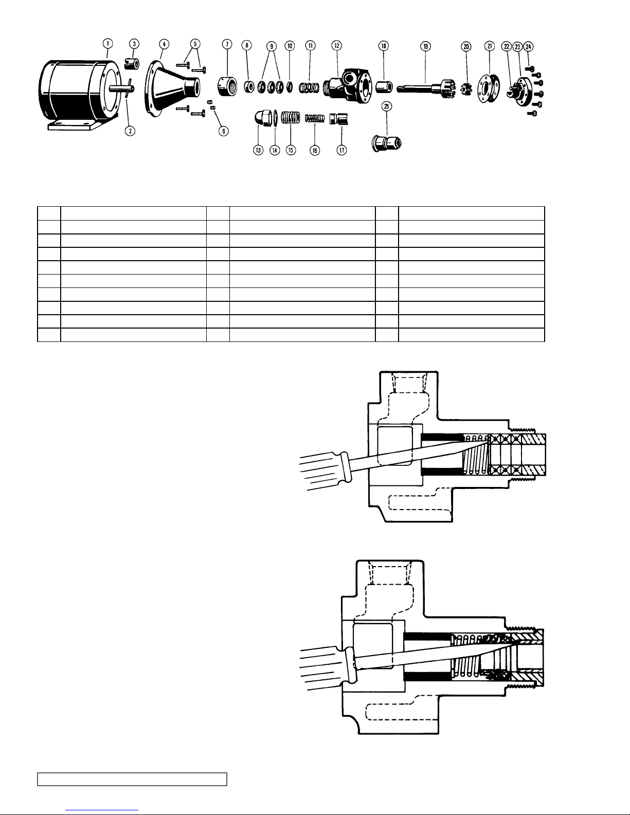
FIGURE 2
EXPLODED VIEW SERIES 56 AND 456
ITEM NAME OF PART ITEM NAME OF PART ITEM NAME OF PART
1 Electric Motor 10 Inner Packing Gland (Series 56 only) 19 Rotor and Shaft Assembly
2 Motor Shaft Pin 11 Packing Spring (Series 56 only) 20 Idler
3 Coupling with Setscrew 12 Casing 21 Head Gasket
4 Mounting Bracket 13 Cap 22 Idler Pin
5 Capscrew for Bracket to Motor 14 Gasket for Cap 23 Head
6 Setscrew for Pump to Bracket 15 Adjusting Screw 24 Capscrew for Head
7 Packing Nut 16 Spring 25 Mechanical Seal (Series 456 only)
8 Outer Packing Gland (Series 56 only) 17 Poppet
9 Packing (Series 56 only) 18 Casing Bushing
1. Remove the capscrews and the head from the pump.
It may be necessary to apply a slight pressure on the
drive end of the rotor shaft to free the head from the
casing. DO NOT PRY the head from the casing as this
may damage and mar the gasket surfaces.
2. Remove idler from idler pin. If the idler pin is worn, both
the head and idler pin, and idler should be replaced.
3. Next, completely remove the rotor and shaft from the
casing by exerting pressure on the drive end of the
shaft.
4. Remove the packing nut.
5. The pump is now ready for removal of packing or
mechanical seal. Refer to Figure 3 or 4 for example. It
is recommended a new mechanical seal or packing be
used every time a pump is completely disassembled.
FIGURE 3
PACKED
(56)
All parts should be examined for wear before the pump is
put together. When making major repairs, such as replacing
a rotor and shaft, it is usually considered advisable to also
install a new casing bushing.
SECTION TSM 320.1 ISSUE F PAGE 4 OF 7
MECHANICAL
SEAL (456)
FIGURE 4
NOTE: SERIES 56 PACKED PUMPS DISCONTINUED AS OF 1Q16.
Page 5

PACKING NUT
ROTARY
SPRING WASHER
MEMBER
SEAL SEAT
RETAINER LUG
CARBON WEAR RING
INSTALLING CASING BUSHING
The casing bushing can be replaced in the following manner:
Insert a bar approximately 0.94” diameter and at least 3.5”
long in the packing or seal end of the casing and press the
bushing out of the casing.
When installing a new carbon graphite bushing, extreme
care should be taken to prevent breakage as carbon graphite
is a brittle material and easily cracked. When cracked the
bushing may quickly disintegrate in operation. An arbor press
should always be used and the bushing should be installed in
one even uninterrupted stroke of the press. Dip the bushing
in lube oil and start the bushing in the head end of the casing.
Press until located to the “A” dimension in Figure 6.
A
HEAD
FACE
FIGURE 6
PUMP SIZE “A” DIMENSION
C 0.88” to 0.94”
F & FH 1.19” to 1.25”
The end clearance within the pump is governed by the location
of the casing bushing as well as the number of head gaskets.
To correctly position the casing bushing in the casing, see
note in step 3 of ASSEMBLY.
SPRING
FIGURE 5
ASSEMBLY
1. Clean all parts thoroughly.
2. Place the rotor and shaft in the casing.
3. Put the head gaskets on the head and the idler on the
idler pin projecting from the head. Replace the head in
the casing; tighten cap screws.
NOTE: If a new casing bushing has been installed in the
casing, use only one .002” head gasket on the head and
tighten the capscrews evenly and securely. This will correctly
position the bushing in the casing. Remove the head, add
one .002” head gasket and replace the capscrews and tighten
securely.
NOTE: Turn the shaft by hand to be certain it turns freely.
4. When reassembling a mechanically sealed pump, place
the spring washer and spring on the shaft, see Figure 5,
Page 4. Coat the shaft and the inside of the rubber
bellows of the seal rotary member with light oil. Slide the
rotary member part way down the shaft.
NOTE: The lapped face of the carbon wear ring must face
toward the shaft end of the pump. Be sure the notches on the
edge of the carbon wear ring mate with the retainer lugs in
the rotary member.
Oil the lapped faces of the rotary member and the seal seat.
Slide the seal seat on the shaft until it contacts the rotary
member and then push the complete seal into the casing.
Replace the packing nut and tighten.
Your pump is now completely assembled. Once again turn
the pump shaft by hand to be sure it turns freely. Start the
pump with a supply of liquid in the suction line, since the
pump should not be run dry.
5. If the pump has packing rather than a mechanical seal,
place the spring and inner packing gland on the shaft and
slide into the pump. Next install the packing. Stagger the
joints in the packing a half turn and add lube oil between
each ring of packing. Push the outer packing gland in the
casing, and replace the packing nut and tighten.
NOTE: SERIES 56 PACKED PUMPS DISCONTINUED AS OF 1Q16.
SECTION TSM 320.1 ISSUE F PAGE 5 OF 7
Page 6
DANGER !
Before starting pump, be sure all drive
equipment guards are in place.
Failure to properly mount guards may
result in serious injury or death.
PRESSURE ADJUSTMENT
DANGER !
Before opening any Viking pump liquid
chamber (pumping chamber, reservoir,
relief valve adjusting cap fitting, etc.)
Be sure:
1. That any pressure in the chamber has
been completely vented through the
suction or discharge lines or other
appropriate openings or connections.
IMPORTANT
In ordering parts for the pressure relief valve, always give
the model number and serial number of the pump as it
appears on the nameplate and the name of the part wanted.
When ordering springs, be sure to give the pressure setting
desired.
2. That the driving means (motor,
turbine, engine, etc.) has been “locked
out” or made non-operational so that
it cannot be started while work is
being done on pump.
3. That you know what liquid the
pump has been handling and the
precautions necessary to safely
handle the liquid. Obtain a material
safety data sheet (MSDS) for the
liquid to be sure these precautions
are understood.
Failure to follow above listed
precautionary measures may result in
serious injury or death.
If a new spring is installed or if the pressure setting of the
pressure relief valve is to be changed from that which the
factory has set, the following instructions must be carefully
followed.
1. Carefully remove the valve cap, which covers the
adjusting screw.
Loosen the locknut, which locks the adjusting screw
so pressure setting will not change during operation of
the pump.
2. Install a pressure gauge in the discharge line for the
actual adjustment operation.
3. Turn the adjusting screw in to increase pressure and out
to decrease pressure.
4. With the discharge line closed at a point beyond the
pressure gauge, the gauge will show the maximum
pressure valve will allow while the pump is in operation.
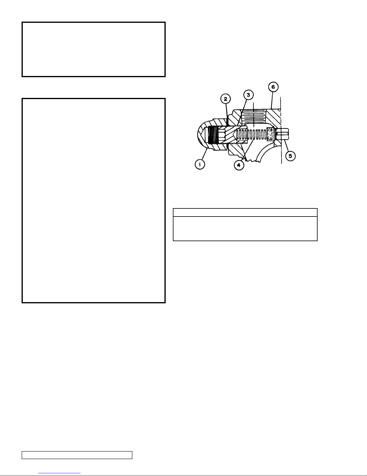
FIGURE 7
PRESSURE RELIEF VALVE - C, F, FH SIZE
VALVE - LIST OF PARTS
Adjusting Screw Cap
1.
Gasket for Cap
2.
Adjusting Screw
3.
4.
5.
6.
Spring
Poppet
Casing
PRESSURE RELIEF VALVE
The relief valve is a pressure device to protect the pump
and motor against excessive pressure. A pump without a
properly set pressure relief valve operating against a closed
discharge line could build up enough pressure to damage
the pump or motor.
The pressure setting is increased by turning the adjusting
screw in and decreased by turning the adjusting screw out.
SPECIAL PUMP DESIGNS
Pumps furnished with a PTFE Mechanical seal require a
special rotor and shaft with drive pin installed for positive drive
of the rotating member. All other assembly and disassembly
instructions are the same.
SECTION TSM 320.1 ISSUE F PAGE 6 OF 7
NOTE: SERIES 56 PACKED PUMPS DISCONTINUED AS OF 1Q16.
Page 7
TECHNICAL SERVICE MANUAL
GENERAL PURPOSE HUB MOUNTED PUMPS
SERIES 56 AND 456
SIZES C - F - FH
WARRANTY
Viking warrants all products manufactured by it to be
free from defects in workmanship or material for a period
of one (1) year from date of startup, provided that in
no event shall this warranty extend more than eighteen
(18) months from the date of shipment from Viking. The
warranty period for Universal Seal series pumps ONLY
is three (3) years from date of startup, provided that in
no event shall this warranty extend more than forty-two
(42) months from the date of shipment from Viking.
UNDER NO CIRCUMSTANCES SHALL VIKING BE
LIABLE UNDER THIS WARRANTY OR OTHERWISE
FOR SPECIAL, INCIDENTAL, INDIRECT,
CONSEQUENTIAL OR PUNITIVE DAMAGES OF ANY
KIND, INCLUDING, BUT NOT LIMITED TO, LOST
OR UNREALIZED SALES, REVENUES, PROFITS,
INCOME, COST SAVINGS OR BUSINESS, LOST OR
UNREALIZED CONTRACTS, LOSS OF GOODWILL,
DAMAGE TO REPUTATION, LOSS OF PROPERTY,
LOSS OF INFORMATION OR DATA, LOSS OF
PRODUCTION, DOWNTIME, OR INCREASED
COSTS, IN CONNECTION WITH ANY PRODUCT,
EVEN IF VIKING HAS BEEN ADVISED OR PLACED
ON NOTICE OF THE POSSIBILITY OF SUCH
DAMAGES AND NOTWITHSTANDING THE FAILURE
OF ANY ESSENTIAL PURPOSE OF ANY PRODUCT.
THIS WARRANTY IS AND SHALL BE VIKING’S SOLE
AND EXCLUSIVE WARRANTY AND SHALL BE IN
LIEU OF ALL OTHER WARRANTIES, EXPRESS
OR IMPLIED, INCLUDING, BUT NOT LIMITED
TO, ALL WARRANTIES OF MERCHANTABILITY,
FITNESS FOR A PARTICULAR PURPOSE AND
NON-INFRINGEMENT ALL OF WHICH OTHER
WARRANTIES ARE EXPRESSLY EXCLUDED.
See complete warranty at www.vikingpump.com.
SECTION TSM 320.1
PAGE 7 OF 7
ISSUE F
NOTE: SERIES 56 PACKED PUMPS DISCONTINUED AS OF 1Q16.
VIKING PUMP, INC. • A Unit of IDEX Corporation • Cedar Falls, IA 50613 USA
© 3/2016 Viking Pump Inc.
All rights reserved
 Loading...