

Page 1
VIKING
Electronics, Inc.
QUICK START GUIDE
K See Product Manual for complete installation and programming instructions.
1.0 Out-of-Box
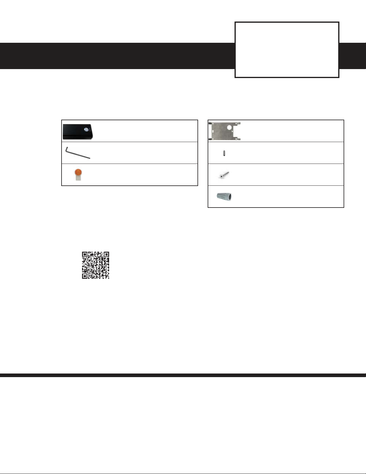
1.1 Verify that you have received all of the parts listed
PB-3-IP
VoIP Emergency Phone
Panic Button
January 3, 2020
X 1
X 1
X 3
PB-3-IP Emergency Phone
Panic Button
Hexkey 5/64
Gel-Filled Butt Connectors
X 1
X 2
X 2
X 1
1.2 Download the product manual
Scan the QR code to
open and download
the product manual
- OR -
1. Go to www.vikingelectronics.com and
enter PB-3-IP in the search box
2. Click PB-3-IP in the search results
3. Click Product Manual to open and
download the PDF
1.3 Download and install the programming software
Back Panel
Screw Set 8-32 Socket
Screw Flat Head Hex Drive 632 x 1.25 Stainless steel
Wire Nut
1. Go to www.vikingelectronics.com and enter PB-3-IP in the search box
2. Click PB-3-IP in the search results
3. Scroll down the page to Downloads, click IP Programming Software
4. Install the programming software by saving or opening the file and then clicking on
setup Viking IP Programming.exe
5. Follow the prompts on your screen to complete software installation
2.0 Power Source
Select PoE Switch or PoE Injector that meets the following requirements:
1. IEEE 802.3af / 802.3at / 802.3bt compliant
2. Capable of providing at least 4 Watts (class 1)
Note: CAT5e (or higher) cable recommended
Page 2
3.0 Network Port Settings
• Make sure the port is not in trunk mode
• Make sure port is capable of 100mbps full duplex
• Disable Spanning Tree Protocol (STP) or enable Portfast
4.0 Features Overview
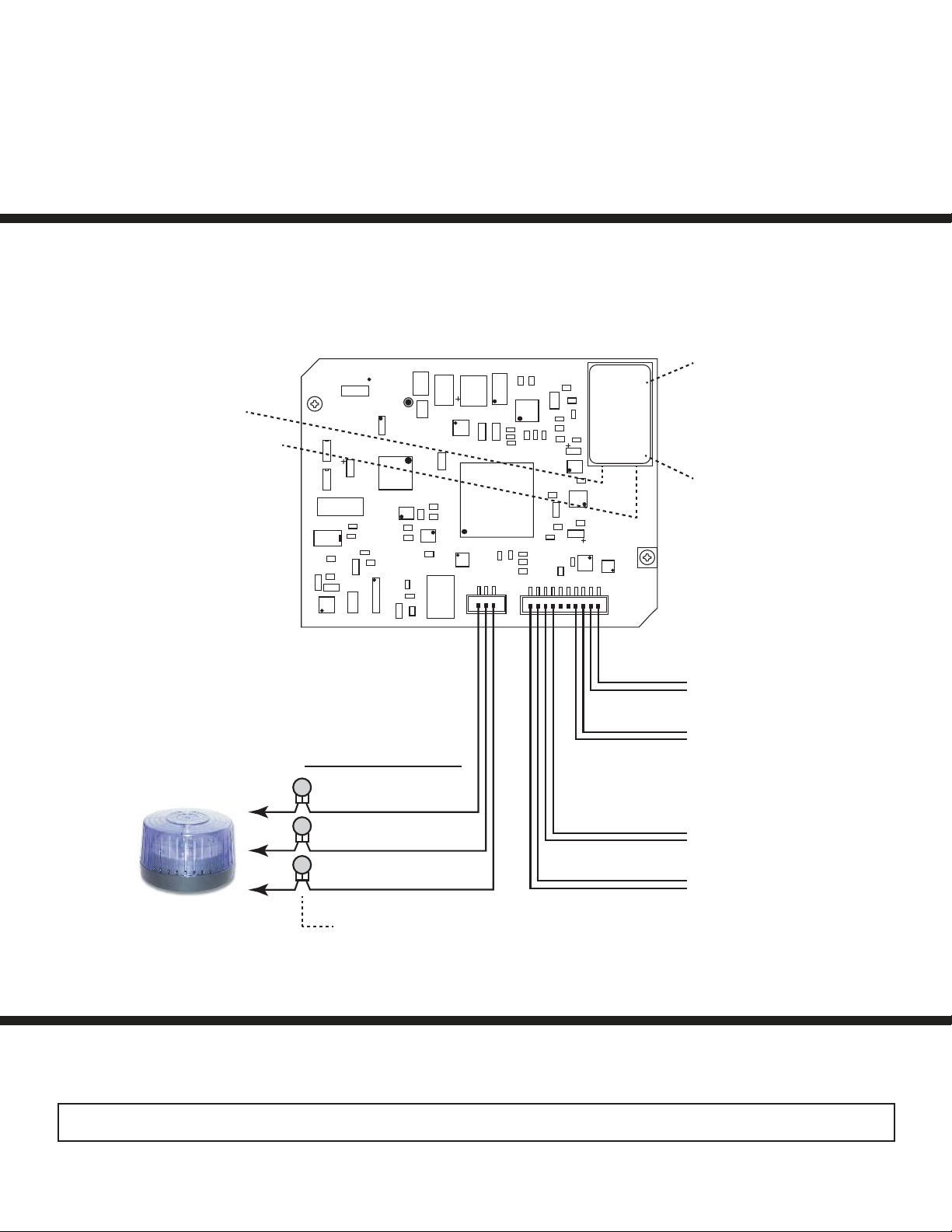
Rear (PCB) View of PB-3-IP
Emergency Phone
Green Unit Status LED
Yellow Network Status LED:
Lights steady to indicate power
and data link. Blinks to indicate
network activity.
18E80FXXXXXX
asdesaxtff
MAC:
PoE LAN Port 10/100,
PoE Class 1 (<4 Watts):
Connect to your LAN via
RJ45 plug and CAT5 or
greater twisted pair wire.
MAC Address Label:
The MAC address is a
unique 12 digit number
used by routers to send
network traffic to the
correct IP address.
Red
LED
Red
Optional 2 Amp Relay
Output Contacts
(2A@30VDC/ 250VAC max)
Black
Black
Panic Button
N.C. (Gray)
Viking model SL-2
shown (not included),
see DOD 242
COM. (Blue)
N.O. (Yellow)
3 Gel-Filled Butt
Connectors (included)
Yellow
Yellow
- Black
+ Red
Speaker
Microphone
Note: The gel-filled (water-tight) butt connectors are designed for insulation displacement on 19-26 gauge wire with a
maximum insulation of 0.082 inches. Cut off stripped wire ends before terminating.
See the Product Manual for complete installation and programming instructions.
Questions? Call Viking Product Support: 715-386-8666
Due to the dynamic nature of the product design, the information contained in this document is subject to change without notice. Viking Electronics, and its affiliates and/or subsidiaries
assume no responsibility for errors and omissions contained in this information. Revisions of this document or new editions of it may be issued to incorporate such changes.
PB-3-IP Quick Start Guide ZF304235 REV 1
 Loading...