

Page 1
Telecommunication Peripheral Products
Technical Practice
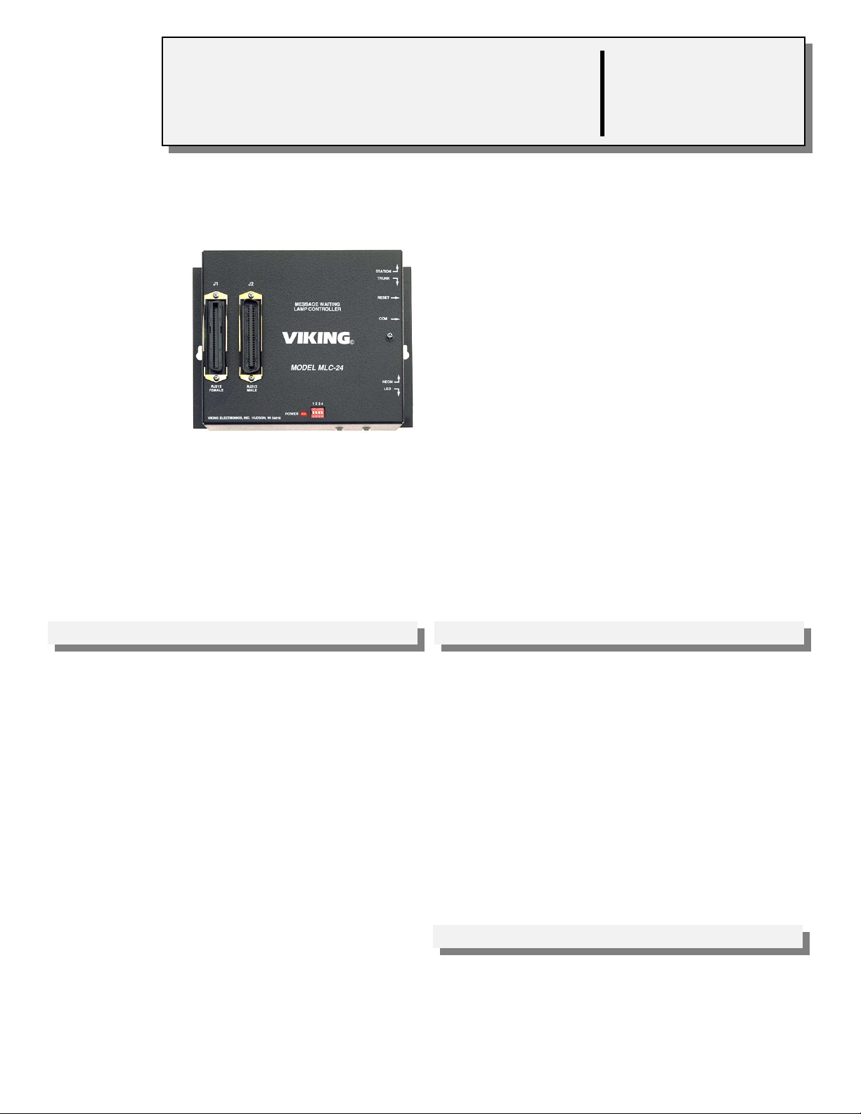
MLC-24
Message Waiting
Lamp Controller
March 2, 1998
Add Message Waiting Lamps for Voice
Mail....On any Telephone System!
With Viking’s MLC-24 you can integrate visual
message waiting indication with nearly any
phone system...even those phone systems
which do not support message lamps.
The MLC-24 is compatible with virtually any
voice messaging system with “out call” or
“dispatch” feature. It can also be activated
manually from a Touch Tone phone. The lamps
can be reset by the voice mail system or from
the user’s telephone.
Commands are sent to the controller via C.O. line or analog PABX/KSU station or trunk
port. Up to four MLC-24 controllers can be connected to a single line.
VIKING©
http://www.VikingElectronics.com
E-mail...Sales@VikingElectronics.com
Features Applications
• Each MLC-24 controls up to 24 message
waiting lamps
• Compatible with 90 to 125V message waiting
phones
• Compatible with LED’s or Viking LM-1 or LM-2
retrofit message waiting lamp kit
• Displays both steady lamp or flash for urgent
messages
• Voice mail systems that don’t provide message
waiting voltage
• Remote voice mail systems
• Staff “In - Out” board
• “Do Not Disturb” lights
Sales...(715) 386 - 8861
• Expandable in multiples of 24 lamps
• Uses existing C.O. lines or analog PABX/KSU
stations
• Built in diagnostics to aid installer
Made in the U.S.A.
Specifications
Power: 120V AC/13.8V AC 1.25A, UL listed, adapter provided
Dimensions: 8.25mm x 160mm x 44mm (8.25” x 6.25” x 1.75”)
Shipping Weight: 1.36 kg (3 lbs.)
Environmental: 0°C to 32°C (32°F to 90°F) with 5% to 95% non-
condensing humidity
Connections: (1) RJ21X male, (1) RJ21X female, (1) RJ11 com
port
Page 2
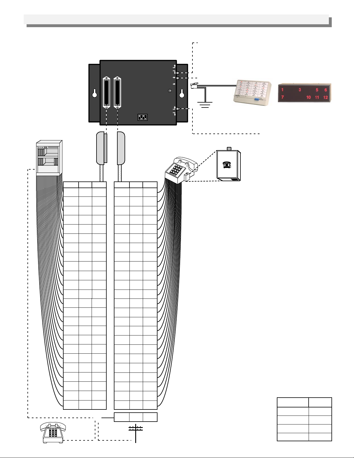
Installation
A. Centrex or PABX Installation with Standard Phones
STATION
TRUNK
RESET
COM
NEON
LED
1000 foot
maximum run
using 26 AWG
wire
Control Lineor
Yellow Black
1 - 24 C.O.
lines or analog
PABX/KSU
stations
(not included)
Circuit Pins
T1
R1
T2
R2
T3
R3
T4
R4
T5
R5
T6
R6
T7
R7
T8
R8
T9
R9
T10
R10
T11
R11
T12
R12
T13
R13
T14
R14
T15
R15
T16
R16
T17
R17
T18
R18
T19
R19
T20
R20
T21
R21
T22
R22
T23
R23
Unused
PABX Trunk
Input or Analog Station
T24
R24
Control
Phone
RJ21 Male
Connector
26
1
27
2
28
3
29
4
30
5
31
6
32
7
33
8
34
9
35
10
36
11
37
12
38
13
39
14
40
15
41
16
42
17
43
18
44
19
45
20
46
21
47
22
48
23
49
24
J1
RJ21X
FEMALE
VIKING ELECTRONICS, INC. HUDSON, WI 54016
Color
W/BL
BL/W
W/O
O/W
W/G
G/W
W/BN
BN/W
W/S
S/W
R/BL
BL/R
R/O
O/R
R/G
G/R
R/BN
BN/R
R/S
S/R
BK/BL
BL/BK
BK/O
O/BK
BK/G
G/BK
BK/BN
BN/BK
BK/S
S/BK
Y/BL
BL/Y
Y/O
O/Y
Y/GN
GN/Y
Y/BN
BN/Y
Y/S
S/Y
V/BL
BL/V
V/O
O/V
V/GN
GN/V
V/BN
BN/V
C.O. Line
J2
MESSAGE WAITING
LAMP CONTROLLER
VIKING©
MODEL MLC-24
RJ21X
MALE
Circuit Pins Color
1T1
1R1
2T1
2R1
3T1
3R1
4T1
4R1
5T1
5R1
6T1
6R1
7T1
7R1
8T1
8R1
9T1
9R1
10T1
10R1
11T1
11R1
12T1
12R1
13T1
13R1
14T1
14R1
15T1
15R1
16T1
16R1
17T1
17R1
18T1
18R1
19T1
19R1
20T1
20R1
21T1
21R1
22T1
22R1
23T1
23R1
24T1
24R1
25T1
25R15025
1 2 3 4
POWER
RJ21 Female
Connector
(not included)
1-24 analog
PABX/KSU
stations
26
1
27
2
28
3
29
4
30
5
31
6
32
7
33
8
34
9
35
10
36
BK/BL
11
BL/BK
37
12
38
13
39
BK/BN
14
BN/BK
40
15
41
16
42
17
43
18
44
19
45
20
46
21
47
22
48
23
49
24
W/BL
BL/W
W/O
O/W
W/G
G/W
W/BN
BN/W
W/S
S/W
R/BL
BL/R
R/O
O/R
R/G
G/R
R/BN
BN/R
R/S
S/R
BK/O
O/BK
BK/G
G/BK
BK/S
S/BK
Y/BL
BL/Y
Y/O
O/Y
Y/GN
GN/Y
Y/BN
BN/Y
Y/S
S/Y
V/BL
BL/V
V/O
O/V
V/GN
GN/V
V/BN
BN/V
V/S
S/V
Station/Trunk Switch - Switch to STATION when
connecting the "control line" to a C.O. line or an analog
PABX/KSU station. Switch to TRUNK when connecting
the "control line" to a dedicated phone or unused (loop
start) trunk input.
Reset Button
Red
Green
Optional LM-24D
(Fax Back Document 670)
Optional LM-12W
or
(Fax Back Document 665)
Connect the Yellow and Black to the positive of the talk
battery, normally earth ground (see
Important
below).
Neon/LED Switch - Switch to
NEON when using standard
90-125V message waiting
Message Waiting
Lamp
MODEL LM-1
VIKING ELECTRONICS
HUDSON, WI 54016
VIKING©
LM-1 (Fax Back Document 660)
phones or Viking Model LM-1
on standard phones.
Most 48 volt C.O. line or analog PABX/KSU
stations require no station rewiring as the 90 to
125 volt signal is superimposed on the existing tip
and ring. The lamp controller is compatible with
standard 90 to 125 volt message waiting lamp
phones as well as Viking model LM-1 retrofit
message waiting lamp kit installed on modular
analog station sets.
Important: The Yellow and Black of the RJ-14
jack, “COM”, MUST be connected to the positive of
the talk battery for proper reference. This is
normally earth ground on most C.O. lines or
analog PABX/KSU stations.
Note: This application requires that the correct
polarity (tip=positive, ring=negative) be observed
on J1 for proper operation.
Diagnostics
After wiring J1, the polarity may be tested using a
volt meter. An easier method is to use a Viking
model LM-24D display in conjunction with the
MLC-24’s built in diagnostics as follows:
1. Be sure that J2 is disconnected and that J1 is
connected and wired.
2. Make sure the BK and Y of the “COM” RJ-14
are connected to the earth ground (positive side
of the battery).
3. Connect a Viking LM-24D display to the COM
jack.
4. Set the dip switches as
shown below.
5. Momentarily press the
reset switch. If any LED’s
remain lit, reverse tip and
ring (going to J1) for that
line, and retest.
Dip Switch
1
2
3
4
Setting
OFF
ON
OFF
ON
Page 3

B. Electronic or Digital Phone Installation with LM-2 Message Waiting Lamps
Station/Trunk Switch - Switch to STATION when
connecting the "control line" to a C.O. line or an analog
PABX/KSU station. Switch to TRUNK when connecting the
"control line" to a dedicated phone or unused (loop start)
trunk input.
Reset Button
Green
Red
Optional LM-24D
(Fax Back Document 670)
or
(Fax Back Document 665)
Neon/LED Switch - Switch to LED when using an LED or
LM-2 on a separate pair.
.75”
LM-2 (Fax Back Document 660)
1.00”
J2
J1
RJ21X
RJ21X
FEMALE
MALE
VIKING ELECTRONICS, INC. HUDSON, WI 54016
MESSAGE WAITING
LAMP CONTROLLER
VIKING©
MODEL MLC-24
1 2 3 4
POWER
STATION
TRUNK
RESET
COM
NEON
LED
Black
Yellow
KSU/Digital Phone with LM-2
Optional LM-12W
RJ21 Male
Connector
(not included)
Pins Color
1
2
3
4
5
6
7
8
9
10
11
12
Pins
13
14
15
16
17
18
19
20
21
22
23
24
Unused PABX
Trunk Input or
Analog station
BL/W
O/W
G/W
BN/W
S/W
BL/R
O/R
G/R
BN/R
S/R
BL/BK
O/BK
Color
G/BK
BN/BK
S/BK
BL/Y
O/Y
GN/Y
BN/Y
S/Y
BL/V
O/V
GN/V
BN/V
or
RJ21 Female
Connector
(not included)
Polarity Pins
+
LED 1
-
+
LED 2
-
+
LED 3
-
+
LED 4
-
+
LED 5
-
+
LED 6
-
+
LED 7
-
+
LED 8
-
+
LED 9
-
+
LED 10
-
+
LED 11
-
+
LED 12
-
+
LED 13
-
+
LED 14
-
+
LED 15
-
+
LED 16
-
+
LED 17
-
+
LED 18
-
+
LED 19
-
+
LED 20
-
+
LED 21
-
+
LED 22
-
+
LED 23
-
+
LED 24
-
25T1
25R1
Color
26
W/BL
1
BL/W
27
W/O
2
O/W
28
W/G
3
G/W
29
W/BN
4
BN/W
30
W/S
5
S/W
31
R/BL
6
BL/R
32
R/O
7
O/R
33
R/G
8
G/R
34
R/BN
9
BN/R
35
R/S
10
S/R
36
BK/BL
11
BL/BK
37
BK/O
12
O/BK
38
BK/G
13
G/BK
39
BK/BN
14
BN/BK
40
BK/S
15
S/BK
41
Y/BL
16
BL/Y
42
Y/O
17
O/Y
43
Y/GN
18
GN/Y
44
Y/BN
19
BN/Y
45
Y/S
20
S/Y
46
V/BL
21
BL/V
47
V/O
22
O/V
48
V/GN
23
GN/V
49
V/BN
24
BN/V
5025V/S
S/V
1000 foot
maximum run
using 26 AWG wire
Control Line
Note: Electronic or digital telephones usually require
a separate dedicated pair for operation of the message
waiting lamps. When a dedicated pair is used, the
MLC-24 can provide low voltage for direct operation of
LED indicators, such as the LM-2.
Programming
A. Assigning Group Lamp Numbers
Additional MLC-24’s can be added for controlling
up to 96 message waiting lights. Set the dip
switches as shown below.
Dip Switch
1
OFF
ON
OFF
ON
2
OFF
OFF
ON
ON
B. Other Dip Switch Settings
Dip switch 3 and 4 can be used to set message
waiting light parameters and operational modes.
Switch
3
3
4
4
Feature
ON
When using hard wired LED’s
OFF
Use with LM-1’s, LM-2’s or message
waiting phones
ON
Test pattern or diagnostics
OFF
Normal operation
Group Number
Assignment
1 - 24
25 - 48
49 - 72
73 - 96
Control Phone
C.O. Line
Page 4

Operation
A control phone connected directly to the MLC-24’s “control line” controls the lamps. The "control line" may also be
connected to a C.O. line, analog PABX/KSU station, or an unused C.O. port.
One MLC-24 controller can serve 24 different station lamps, plus up to three 24 line status displays (LM-24D or LM-
12W) for the receptionist(s). Up to four MLC-24’s can be installed on a single extension or line.
In voice mail applications the “dispatch” or “out-call” feature is used to call the extension assigned to the MLC-24, which
answers and provides a 500 Hz tone. The voice mail system then sends a three digit DTMF code that specifies the
status of an individual lamp. For example, a Touch Tone code of “1, 24” would cause lamp 24 to be off, a “2, 24” would
cause it to be on steady, a “3, 24” would cause it to flash and a “4, 24” would cause it to fast flash. When the three digit
code is complete, the MLC-24 hangs up. The 3 digit code can also be entered manually from any Touch Tone phone.
In applications where a ringing extension is not available, the MLC-24 can be programmed to provide talk battery for
direct connection to an unused trunk input, a standard DTMF phone or the voice mail “dispatch” or “out-call” port, if
compatible.
A. On Premise Operation
When the MLC-24 is connected to a station circuit of a
PABX, the voice mail system or user must first dial the
station (extension) number connected to the MLC-24’s
“control line.” The MLC-24 will answer with a steady
tone. The command codes can then be entered as
shown in the table to the right.
B. Off Premise Operation
When the MLC-24 is located in a remote facility, the voice mail system or user must call the telephone number of the
phone line connected to the “control line” of the MLC-24 (J2 Pins 25, 50). The MLC-24 will answer with a steady
tone. The command codes can then be entered as shown in the table.
Signaling the MLC-24...
1. ...to turn lamp OFF at station xy*
2. ...to turn lamp ON at station xy*
3. ...to flash a lamp at station xy*
4. ...to fast flash a lamp at station xy*
5. ...to turn all lamps OFF
* xy refers to numbers 1 - 96
Enter Digits
1 + xy*
2 + xy*
3 + xy*
4 + xy*
1 - 4 + 99
C. Message Waiting Lamp Illumination
1. Neon Message Waiting Phones and/or LM-1 Modular Message Waiting Lamp Retrofit Kit
This kit will illuminate when the receiver is on-hook. They will go out when the receiver is off-hook and go on as
the receiver is returned on-hook. The lamp may be extinguished by an off Touch Tone code or by momentarily
(.25 - 2 seconds) going off hook.
2. LM-2 LED Message Waiting Lamp Kit
This kit will illuminate immediately and remain on until the LM-2 switch is depressed momentarily (.25 - 2
seconds) or an off Touch Tone code is issued to extinguish the LED.
3. LED’s
These will illuminate immediately and remain on until an “off” Touch Tone code is issued to extinguish the LED.
D. Power Failure
In the event of AC power failure, the message waiting lamps will not function. All telco operations will operate as
normal.
E. Special Features
1. With switch positions 1 and 3 in the OFF position and 2 and 4 in the ON position, the display will indicate on or
off hook condition for 24 lines (off-hook = LED is on, on-hook = LED is off).
the MLC-24 after changing switch positions.
2. With switch positions 2 and 3 in the “off” position and 1 and 4 in the “on” position, the installer can generate a test
pattern that will aid in the installation. The MLC-24 will turn the lamps on one at a time, then turn them all off.
This will continue until the switches are placed back into position for normal operation.
Note: Depress the reset button on
Product Support Line...(715) 386-8666 Fax Back Line...(715) 386-4345
Due to the dynamic nature of the product design, the information contained in this document is subject to change without notice. Viking
Electronics, its affiliates and/or subsidiaries assume no responsibility for errors and/or omissions contained in this information. Revisions of
this document or new editions of it may be issued to incorporate such changes.
Printed in the U.S.A. ZF290220 Rev CFax Back Doc # 675
 Loading...