

Viking VSOC530SS, MVSOC530SS Installation Manual
Installation Guide
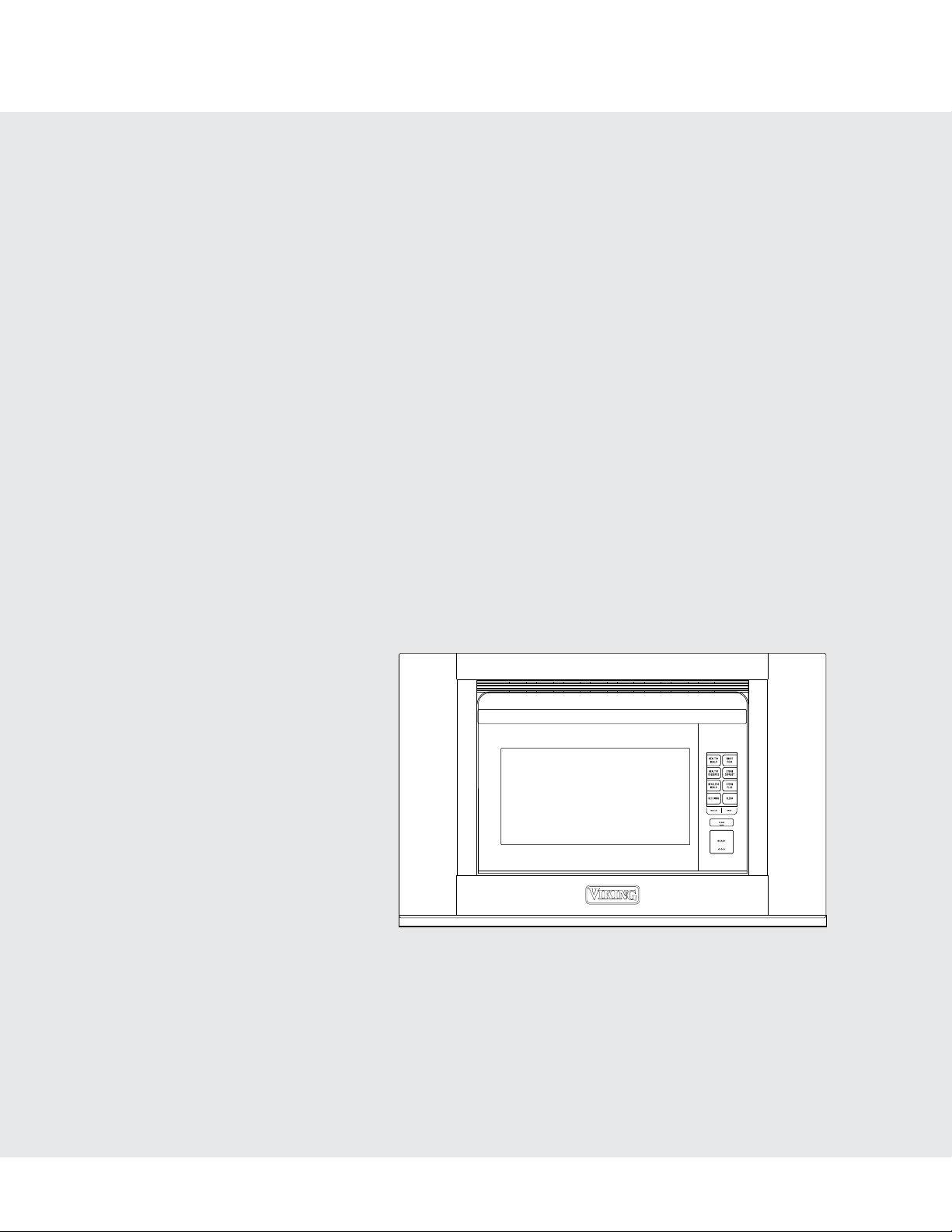
Built-in Combi Steam/Convect™ Oven
MVSOC530SS
IMPORTANT–Please Read and Follow!
• Before beginning, read these instructions thoroughly
and carefully.
• Because the kit includes metal parts, caution should
be used in handling and installation to avoid the possibility of injury.
• Do not remove permanently affixed labels, warnings or
plates from the product as this may void the warranty.
• Observe all local and national codes, requirements
and ordinances.
• Installers should leave these instructions with the consumer who should retain them for the local inspector’s
use and for future reference.
ELECTRICAL GROUNDING INSTRUCTIONS
This oven must be electrically grounded in
accordance with local codes or, in the absence
of local codes, with the National Electrical Code,
ANSI/NFPA 70 – latest edition.
IMPORTANT SAFETY
INSTRUCTIONS
• WARNING: If the information in this manual is not
followed exactly, a fire or electrical shock may result
that could cause property damage, personal injury
or death.
• This appliance must be electrically grounded in accordance with local codes.
• Make sure the wall coverings and the cabinets around
the oven can withstand the heat generated by the
appliance.
• WARNING: Never leave children alone or unattended
in the area where a appliance is in use.
• Do not use the oven as a storage space. This creates
a potentially hazardous situation.
DO NOT USE AN EXTENSION CORD
WITH THIS APPLIANCE. SUCH USE MAY RESULT
IN FIRE, ELECTRICAL SHOCK OR OTHER
PERSONAL INJURY.
E2
Unpacking your Combi
Steam/Convect Oven
™
Electrical Outlet
• Remove all packing materials from inside the oven.
• Check the oven for any damage, such as misaligned or
bent oven, damaged oven seals and sealing surfaces
or dents inside the cavity or on the front side of the
oven. If there is any damage, do not operate the oven
and contact your AUTHORIZED SERVICER.
Important Notes to the
Installer
• Read all of the Installation Guide before installing
the oven.
• Remove all packing material before connecting the
electrical supply.
• Observe all governing codes and ordinances.
• Be sure to leave these instructions with the consumer.
Important Notes to the
Consumer
Keep this manual with your Use and Care Manual for
future reference.
• As when using any oven generating heat, there are
certain safety precautions you should follow. These
are listed in the Use and Care Manual. Read all and
follow carefully.
• Be sure your oven is installed and grounded properly
by a qualified installer or service technician.
• The electrical requirements are a 120 volt 60 Hz, AC
only, 15 amp. or more protected electrical supply. It
is recommended that a separate circuit serving only
this appliance be provided.
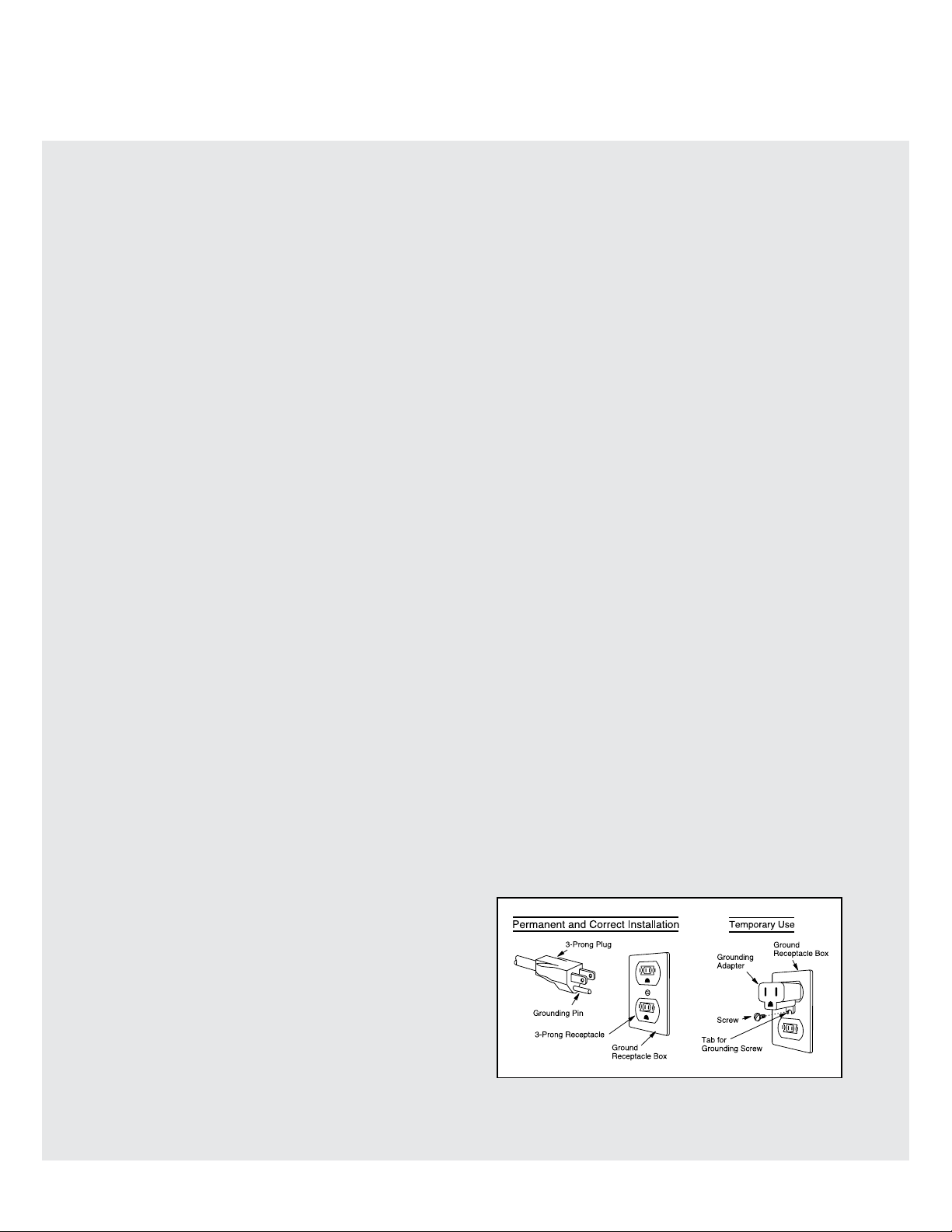
• The appliance is equipped with a 3-prong grounding
plug. It must be plugged into a wall receptacle that is
properly installed and grounded. Should you only have
a 2-prong outlet, have a qualified electrician install a
correct wall receptacle.
Note:
If you have any questions about the grounding or electrical instructions, consult a qualified electrician or service
person.
* Can also be installed using an electrical outlet in an
adjacent cabinet within the area where the provided
electrical cord can reach.
Always check electrical codes for requirements.
GROUNDING
INSTRUCTIONS
This appliance must be grounded. The oven is equipped
with a cord having a grounding wire with a grounding
plug. It must be plugged into a wall receptacle that is
properly installed and grounded in accordance with the
National Electrical Code and local codes and ordinances.
In the event of an electrical short circuit, grounding reduces risk of electric shock by providing an escape wire
for the electric current.
WARNING: Improper use of the grounding plug can
result in a risk of electric shock. Do not use an exten-
sion cord. If the power supply cord is too short, have
a qualified electrician or serviceman install an outlet
near the appliance.
E3
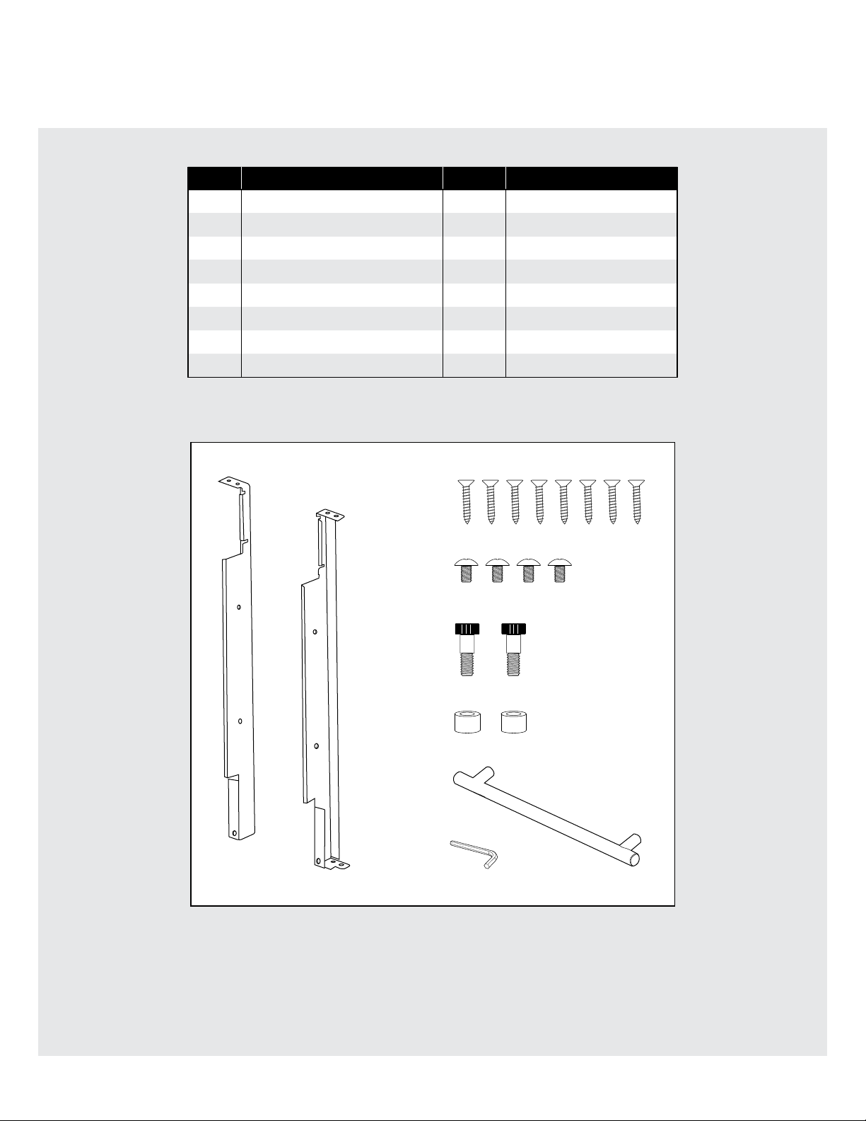
Installation Hardware
ITEM NAME QTY PART CODE
1
2
3
4
5
6
7
8
Left Mounting Bracket 1 LANGTB407MRP0
Right Mounting Bracket 1 LANGTB408MRP0
Wood Screws 8 XTSS740P20000
Mounting Bolts 4 LX-CZB069MRE0
Shoulder Bolts 2 LX-CZB068MRE0
Shoulder Bolt Sleeves 2 PCOVPB226MRE0
Handle 1 JHNDMB008MRE0
Allen Wrench 1 UKOGMB003MRE0
1
2
3
4
5
6
7
8
E4
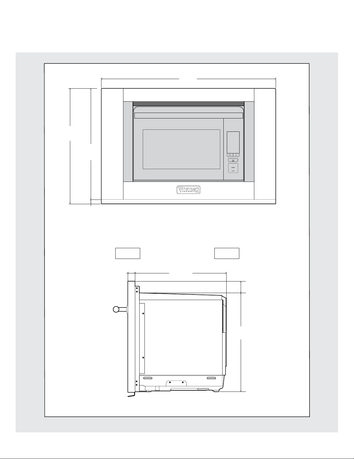
Oven Measurements
7
19
/8"
(504.8 mm)
1
/16"
19
(484.1 mm)
3
/4"
(19.05 mm)
29
(756 mm)
Figure 1A
3
/4 "
FRONT BACK
1
1
/4"
(32 mm)
15 21/32"
(397.6 mm)
Figure 1B
1
2
/64"
(51.18mm)
15
16
/16"
(430.2 mm)
E5
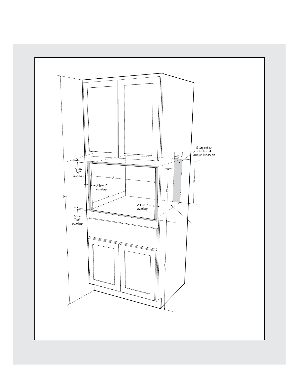
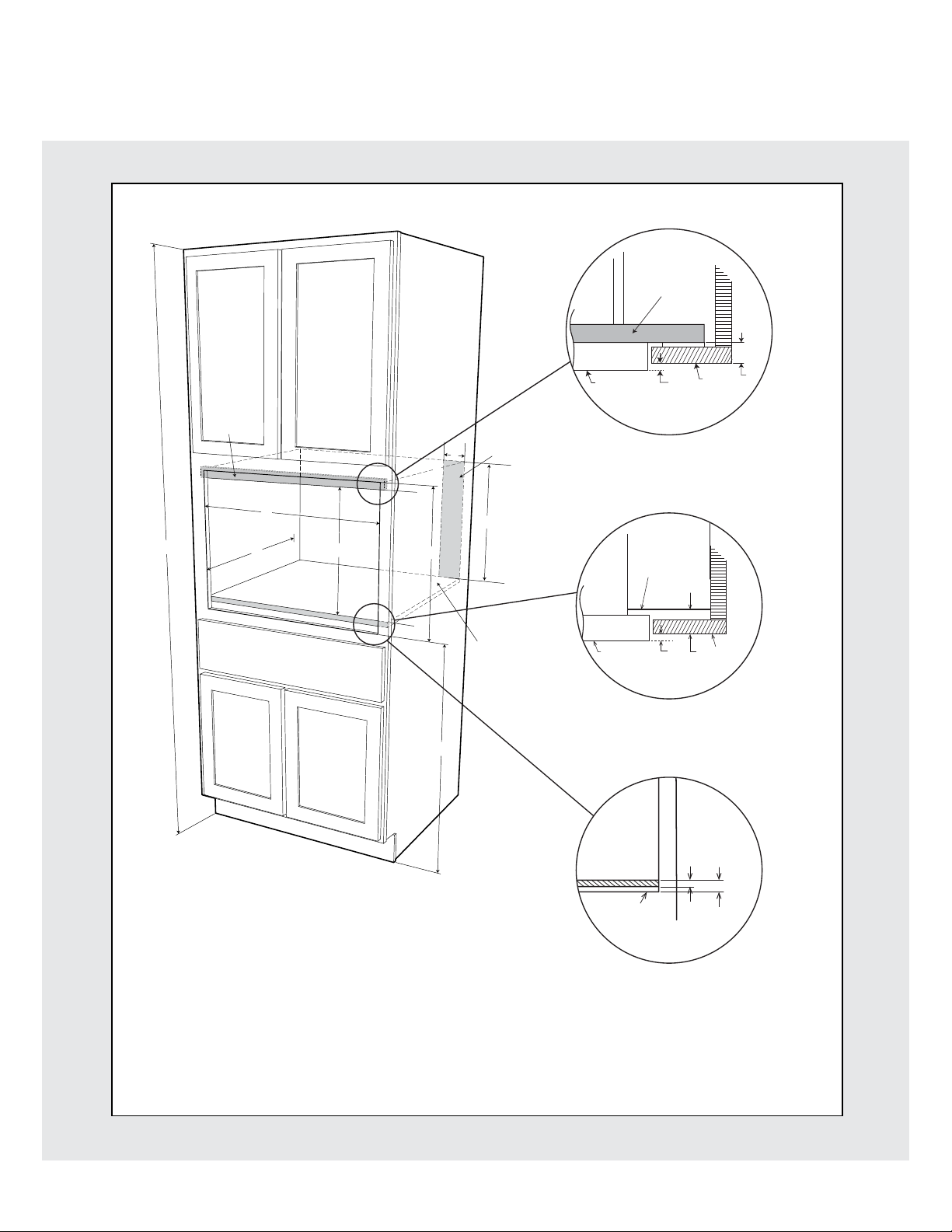
Clearances and Dimensions for Standard Surface Mount
A. 27 15/16" cutout
1
B.
18
/8" cutout*
3
C. 15
D.
E. 4"
F. 18"
/4" min. depth
33" min. height
Figure 2
* Critical dimension
Note: Platform
must be able to
support 70 lbs.
E6E6
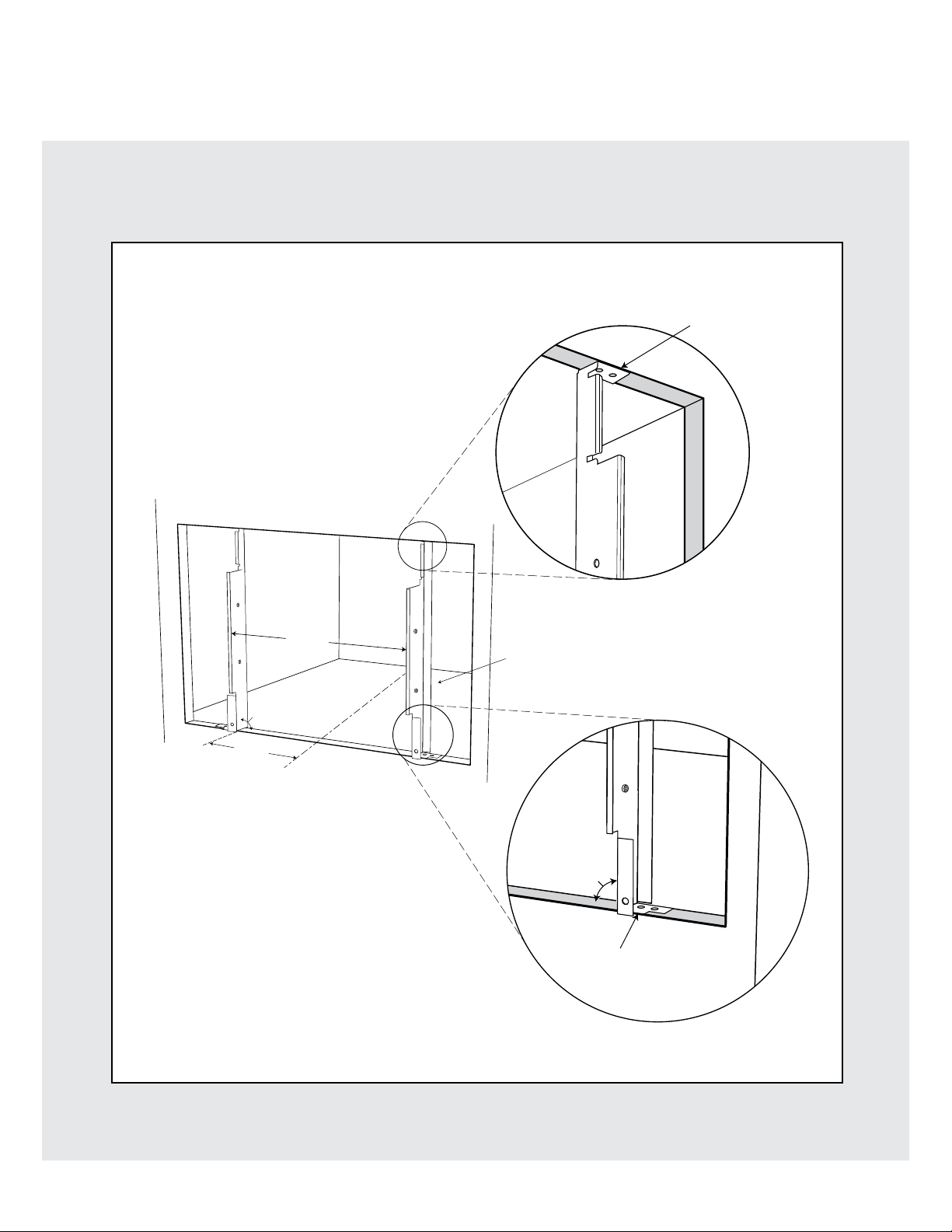
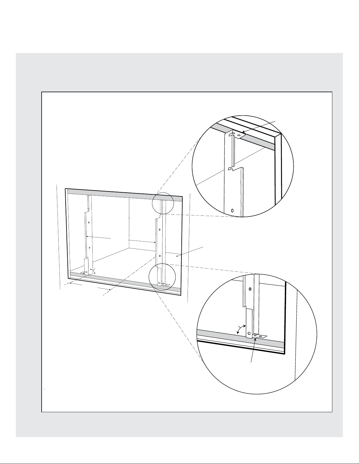
Installation Instructions for Standard Surface Mount
1. Mounting brackets should be installed with the 8 wood screws provided, 19 ¼" apart from each other and centered
in the cabinet opening. Locate position, center punch and drill pilot hole
1
/8". See Figure 3.
Front of flange even
with front of surface
19 1/4"
*90˚
5
9
"
/8
C
*Note:
Square the mounting bracket
to the opening and shelf
L
Note: Platform must be
able to support 70 lbs.
90˚
Front of flange even
with front of cabinet face
Figure 3
E7
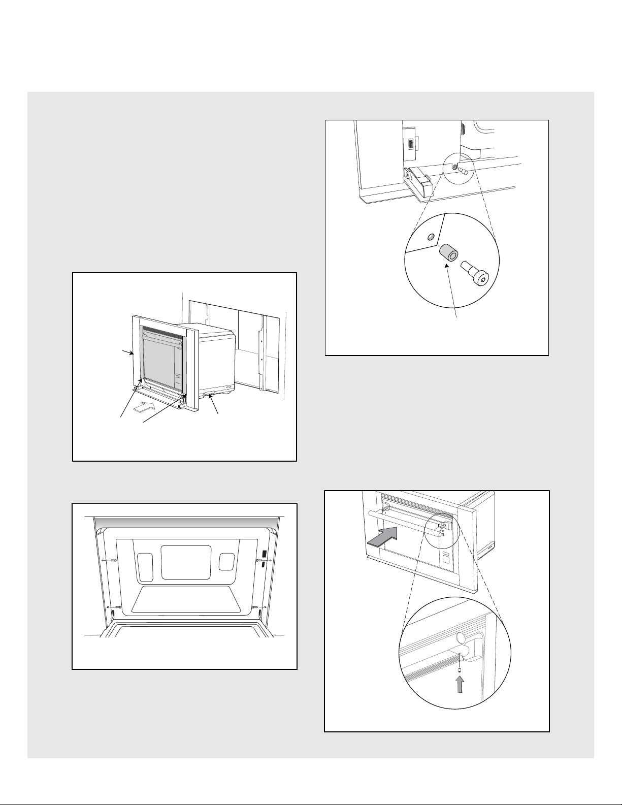
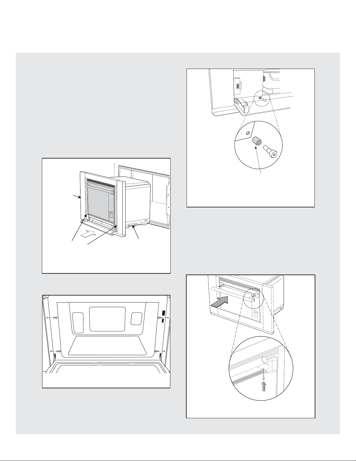
Installation Instructions for Standard Surface Mount
Note: Slide on shoulder bolt sleeves before mounting
WARNING Always take caution lifting heavy products.
2. Use a minimum of 2 people to lift and install oven.
Place the oven adjacent to the cabinet opening,
see Figure 4. Plug the power supply cord into the
electrical outlet.
3. Carefully guide the oven between the mounting
brackets. Avoid pinching the cord between the oven
and the brackets.
4. Slide the oven all the way back until the oven frame
is seated against the cabinet and the mounting
brackets.
DO NOT
lift this unit
using the outer
oven frame
Figure 6
Lift point
Side Handle (x2)
Figure 4
5. Open the oven door and insert the 4 mounting bolts
supplied. Do not completely tighten. See Figure 5.
Figure 5
7. Check alignment of oven then tighten the 4
mounting bolts in Figure 5 and the 2 shoulder bolts
in Figure 6 to secure oven.
8. Install Handle. Loosen the two set screws on the
handle, apply lock tite to the set screws. Slide the
handle over the studs on the oven door and tighten
the set screws using the provided allen wrench.
Note: the set screws on the handle should be facing
down during installation. See Figure 7.
6. Open the drip tray door and insert the 2 shoulder
bolts supplied. See Figure 6. Do not completely
tighten.
Figure 7
E8
Clearances and Dimensions for Flush Mount
Block added
by cabinet
installer
Block added
by cabinet
installer
F
Suggested
electrical
outlet location
Steam oven
face
Note: the mounting surface of the top block
must sit 1" back from the face of the cabinet.
(allowing the face of the steam oven out
H
Detail A
Top View
Cabinet
face
I
1
/4")
A
84"
D
A. min. 30" max. 30 1/16"
B. 20" cutout
1
C. 18
/8" opening*
3
D. 15
/4" min. depth
E. 33" min. height
F. 4"
G. 18"
C
1
/4"
H.
B
I. 1"
J. 1"
3
/4" platform thickness
K.
7
L.
/8" top of platform
to bottom of cutout
E
G
Note: Platform
must be able to
support 70 lbs.
Platform edge
H J
Steam oven
face
Detail B
Cabinet
face
Top View
Note: the front surface of the platform must
sit 1” back from the face of the cabinet.
(allowing the face of the oven out
K L
Cabinet
cutout
1
/4")
Detail C
Front View
3
Note: the top of the
/4" shelf sits 1" from
the bottom of the cabinet cutout.
* Critical dimension
Figure 8
E9
Installation Instructions for Flush Mount
1. Install mounting brackets 19 1/4" with the 8 wood screws provided. Locate position, center punch and drill pilot
1
hole
/8". See Figure 9.
Front of flange even
with front of surface
of the installed
block
1
19
/4
*90˚
5
9
"
/8
C
*Note:
Square the mounting bracket
to the opening and shelf
L
"
Note: Platform must be
able to support 70 lbs.
90˚
Front of flange even
with front of the platform
Figure 9
E10
Installation Instructions for Flush Mount
WARNING Always take caution lifting heavy products.
2. Use a minimum of 2 people to lift and install oven.
Place the oven adjacent to the cabinet opening,
see Figure 10. Plug the power supply cord into the
electrical outlet.
3. Carefully guide the oven between the mounting
brackets. Avoid pinching the cord between the oven
and the brackets.
4. Slide the oven all the way back until the oven frame
is seated against the cabinet and the mounting
brackets.
Note: Slide on shoulder bolt sleeves before mounting
DO NOT
lift this unit
using the outer
oven frame
Figure 12
Lift point
on frame
Figure 10
5. Open the oven door and insert the 4 mounting bolts
supplied. Do not completely tighten. See Figure 11.
Figure 11
Side Handle (x2)
7. Check alignment of oven then tighten the 4
mounting bolts in Figure 11 and the 2 shoulder bolts
in Figure 12 to secure oven.
8. Install Handle: Slide the handle over the studs on
the oven door and tighten the set screws using the
provided allen wrench.
Note: the set screws on the handle should be facing
down during installation. See Figure 13.
6. Open the drip tray door and insert the 2 shoulder
bolts supplied. See Figure 12. Do not completely
tighten.
Figure 13
E11
 Loading...