

Page 1

Chapter 1
Introduction
Table of Contents
About This Manual............................................................................. 1 - 1
Regulatory Standards.............................................................................. 1 - 1
Standard Notations............................................................................ 1 - 2
Safety Summary...................................................................................... 1 - 2
Preventive Maintenance..................................................................... 1 - 5
Inspecting the System.............................................................................. 1 - 5
Cleaning the System................................................................................ 1 - 5
Cleaning the Monitor Screen................................................................... 1 - 5
Revision 3/23/01 i
Page 2

Viking Select Service Manual
Introduction......................................................................................... 2 - 1
Chapter 2
System
Overview
VikingSelect Block Description......................................................... 2 - 2
Power Distribution.................................................................................. 2 - 2
Computer Platform.................................................................................. 2 - 2
Patient Signal Path Components...................................................... 2 - 4
Video Path Components.......................................................................... 2 - 4
FireWire Card.......................................................................................... 2 - 4
FireWire Cabling..................................................................................... 2 - 5
Stimulators .............................................................................................. 2 - 5
Software .................................................................................................. 2 - 5
ii 3/23/01
Page 3

Chapter 3
Software
Table of Contents
Software Overview............................................................................. 3 - 1
Partitions & File Systems........................................................................ 3 - 2
Administrative Tools............................................................................... 3 - 2
NT Software Load - Juneau............................................................... 3 - 5
Initial System Software Load.................................................................. 3 - 5
Deleting Partitions................................................................................... 3 - 6
Loading Windows NT ............................................................................ 3 - 7
Configuring Windows NT ....................................................................... 3 - 7
D-drive Configuration............................................................................. 3 - 8
Installing Microsoft Word 2000.............................................................. 3 - 8
Installing NicVue Software .................................................................. 3 - 10
Installing VikingSelect Master & Application Software....................... 3 - 10
Completing Report MSW Install........................................................... 3 - 11
Image Recovery Procedure................................................................... 3 - 13
Diagnostics....................................................................................... 3 - 19
Overview............................................................................................... 3 - 19
Icon Descriptions................................................................................... 3 - 19
FW Host ................................................................................................ 3 - 22
VikingSelect Service Manual iii
Page 4

Viking Select Service Manual
Introduction......................................................................................... 4 - 1
Chapter 4
Field Service
Procedures
System Options.................................................................................. 4 - 2
Footswitch............................................................................................... 4 - 2
EMG Speaker.......................................................................................... 4 - 2
D-Stim Breakout Box.............................................................................. 4 - 2
Control Panel........................................................................................... 4 - 2
System Cabling - Options.................................................................. 4 - 3
System Cabling - Power Distribution............................................... 4 - 4
System Cabling - System Controller................................................ 4 - 5
System Cabling - Stimulators............................................................ 4 - 6
Power Supplies and Power Distribution.......................................... 4 - 7
Unicart Isolated Power Supply................................................................ 4 - 7
Generation II Cart Firewire Isobox Data Sheet................................ 4 - 9
Connector List........................................................................................ 4 - 9
Connector Pin-outs, CPU Aux Power..................................................... 4 - 9
FireBrick Isobox.................................................................................... 4 - 11
Computer Platform........................................................................... 4 - 12
Hardware Components.......................................................................... 4 - 12
Software Components........................................................................... 4 - 12
Field Adjustments/Maintenance............................................................ 4 - 12
Testing/Troubleshooting........................................................................ 4 - 13
Circuit Board Removal/Replacement.................................................... 4 - 13
Replacing the CMOS Battery................................................................ 4 - 13
Juneau IRQ/DMA Resource Settings.................................................... 4 - 17
Additional Information.......................................................................... 4 - 17
Computer Peripherals...................................................................... 4 - 18
Floppy Drive ......................................................................................... 4 - 19
IDE Hard Drive..................................................................................... 4 - 19
CD-Writer.............................................................................................. 4 - 20
Keyboard............................................................................................... 4 - 20
Mouse ................................................................................................... 4 - 21
Printers .................................................................................................. 4 - 21
Printer Drivers....................................................................................... 4 - 21
HP Deskjet Printers .............................................................................. 4 - 21
Okidata Printer Information.................................................................. 4 - 23
Equipment Carts.................................................................................... 4 - 24
Data Storage & Archive Options..................................................... 4 - 25
Patient Signal Path........................................................................... 4 - 26
Hardware Components.......................................................................... 4 - 26
Software Components........................................................................... 4 - 26
Amplifiers.......................................................................................... 4 - 27
2, 4 & 8-Channel Amplifiers................................................................. 4 - 27
ET 16A(B) Electrode Headbox............................................................. 4 - 31
iv 3/23/01
Page 5

Chapter 4
Field Service
Procedures
(continued)
Table of Contents
Display.............................................................................................. 4 - 32
Hardware Components.......................................................................... 4 - 32
Software Components........................................................................... 4 - 32
Graphics Board...................................................................................... 4 - 32
Field Adjustments/Maintenance............................................................ 4 - 32
Network............................................................................................. 4 - 33
Hardware Components.......................................................................... 4 - 33
Software Components........................................................................... 4 - 34
Network Setup....................................................................................... 4 - 34
NicVue Setup......................................................................................... 4 - 36
Field Adjustments/Maintenance............................................................ 4 - 38
Testing/Troubleshooting........................................................................ 4 - 38
Network Problems................................................................................. 4 - 39
Invalid DCM Error Message................................................................. 4 - 41
Network Vocabulary.............................................................................. 4 - 41
Additional Information.......................................................................... 4 - 41
Stimulators........................................................................................ 4 - 42
Visual Stimulators................................................................................. 4 - 42
2015 Pattern Reversal............................................................................ 4 - 42
LED Goggles......................................................................................... 4 - 43
Ganzfeld Stimulator.............................................................................. 4 - 44
Auditory Stimulator............................................................................... 4 - 47
Auditory Stim Board............................................................................. 4 - 47
TDH-39 Headphones............................................................................. 4 - 48
TIP 300 Tubal Insert.............................................................................. 4 - 48
Bone Vibrator........................................................................................ 4 - 49
Electrical Stimulator.............................................................................. 4 - 50
1-Channel Electrical Stimulator Board & 405-1................................... 4 - 50
2-Channel Electrical Stim & 405-2....................................................... 4 - 50
IES 9...................................................................................................... 4 - 51
S403 Probe ............................................................................................ 4 - 54
VikingSelect Service Manual v
Page 6

Viking Select Service Manual
VikingSelect Certification Checklist................................................. 5 - 1
Chapter 5
Certification
Procedures
VikingSelect System Certification Procedure.................................. 5 - 2
Graphics Diagnostics............................................................................... 5 - 4
QA Disk Verify........................................................................................ 5 - 4
Printer.................................................................................................... 5 - 10
Speaker/Volume Control ....................................................................... 5 - 10
Electrical Stimulator A.......................................................................... 5 - 10
Reflex Hammer..................................................................................... 5 - 11
Amplifier System .................................................................................. 5 - 12
Stimulus Pulse (Stim 1/ Stim2) ............................................................. 5 - 15
Performing Verification Tests................................................................ 5 - 15
vi 3/23/01
Page 7

Chapter 6
Appendix
Table of Contents
Least Replaceable Units................................................................... A - 1
Accessories ............................................................................................ A - 1
Amplifiers & Amp Accessories............................................................. A - 1
Cables..................................................................................................... A - 2
Carts and Cart Accessories.................................................................... A - 3
Circuit Board ......................................................................................... A - 4
Power Cords, Adapters .......................................................................... A - 4
Documentation ........................................................................... A - 5
Drives .................................................................................................. A - 5
Fuses/Lamps........................................................................................... A - 6
Keyboard/Console ................................................................................ A - 6
Mouse .................................................................................................. A - 6
Monitor................................................................................................... A - 6
Power Supply ......................................................................................... A - 6
Mechanical ............................................................................................ A - 7
Miscellaneous......................................................................................... A - 7
Modules.................................................................................................. A - 7
Printers ................................................................................................... A - 7
Processor ................................................................................................ A - 7
Stimulators & Accessories .................................................................... A - 8
Software ................................................................................................. A - 9
VikingSelect Service Manual vii
Page 8

Viking Select Service Manual
Blank Page
viii 3/23/01
Page 9

About This Manual
Chapter 1
Introduction
This manual describes the basic theory, field service
procedures, and troubleshooting of the VikingSelect. It
is intended for use by a quali fied person w ith electr onics
or computer repair experience.
The VikingSelect and its satellite stations are based on
standard computer platforms. For comprehensive
information on repairing computer platforms, we
recommend a general reference book such as Scott
Mueller’s Upgrading and Repairing PCs published by
Que.
Chapter 2 - System Overview
The System Overview section provides a theoretical
basis for understanding the operation of the
VikingSelect. The information is in the form of block
diagrams, functional descriptions and signal flow
diagrams.
Chapter 3 - Software
The Software section contains inf ormation p ertaining to
complete and partial reloading system software and
upgrade software loading. This chapter references
sections in Chapter 5 - Certification for system
operation verification.
Chapter 4 - Field Service Procedures
The Field Service Procedures section contains reference
information for repairing the VikingSelect to the Least
Replaceable Unit (LRU) level. Cabling diagrams, board
layouts, jumper settings and repair procedures are
provided in this section.
Chapter 5 - Certification
The Certification section provides complete certification
check lists and procedures for the VikingSelect.
Chapter 6 - Appendix
The Appendix lists part numbers for the VikingSelect
Least Replaceable Units (LRUs).
Regulatory Standards
Nicolet systems meet the following standards set by
domestic and international regulatory agencies:
• UL 2601
• CSA 22.2 M90
• IEC 601-1
• EN 60601-1
• EN 60601-2-26 for Medical Electronic Equipment
• IEC601-1-1
Networked systems meet the standards listed above for
leakage and Hi-pot.
To meet these standards when systems other than
Nicolet systems are connected to the network, the
following type of wiring must be used:
• Twisted pair wiring port connected to the network
board.
Revision 3/23/01 1 - 1
Page 10

VikingSelect Service Manual
Standard Notations
Specific notations are used in this manual to call
attention to conditions which could result in injury,
damage to the equipment, or require special attention.
Be sure to review the Safety Summary immediately
following this definition of notations.
This warning is used to describe an operating or
maintenance procedure practice or condition which,
if not strictly observed, could result in personal
injury or serious damage to equipment.
This caution is used to describe an operating or
maintenance procedure, practice, cond ition or st atement
which, if not strictly observed, could result in damage to
equipment.
Safety Summary
Do not turn on any system power until all cables
have been properly connected and verified.
This system is not explosion proof. Do not use in the
presence of flammable anesthetics.
Although patient connections are electrically
isolated, these connections are not intended for
direct cardiac contact.
Observe the following precautions during
interoperatative monitoring.
• Use the largest surface area electrode p ossible for the
patient ground electrode.
• A void prolong ed activation of the Electrosur gery u nit
(ESU).
NOTE:
This note is used to describe an essential procedure,
condition, or statement which requires special attention.
• Avoid ESU activation in close proximity of the
monitoring electrodes.
When using electrodes with 2mm pin connectors,
prevent potential injury to your patient by taking the
following precautions:
• Check all cable connections for proper hook up.
• Switch on the monitor to verify it is connected
properly.
• Check that the patient electrode(s) is connected to the
correct amplifier jack.
• Disconnect all detached power cables from the AC
power supply.
• Remove all unused power cables from the location of
the monitoring device.
1 - 2 Revision 3/23/01
Page 11

This system is for use with the Nicolet 800VA Isolation
Box or the iso-box originally supplied with the system.
This equipment uses a three wire power cord with a
hospital grade plug (for international applications, IEC
601-1 approved plug). The chassis is earth grounded.
For grounding reliability, connect the device to a
hospital grade or hospital only receptacle (for
international applications, IEC 601-1 approved
receptacle). Inspect the power cord often for fraying or
other damage. Do not operate the apparatus with a
damaged power cord or plug. Improper grounding is a
safety hazard.
Connect the device to Nicolet Biomedical supplied or
recommended accessories.
Do not allow conductive parts of electrodes and
connectors to contact conductive parts or ground.
Introduction
Always use appropriate Bovie protection devices with
amplifiers for connecting all recording electrodes. Use
the largest surface area electrode possible for the p atient
ground electrode. Avoid prolonged activation of the
Electrosurgery Unit (ESU). Avoid ESU activation in
close proximity of the monitoring electrodes.
When more than one medical device is connected to the
patient, leakage currents of the devices are summed
together. Use caution.
Periodically check the system ground integrity, the
system leakage current and the leakage current of the
amplifier.
This equipment is not protected against defibrillation.
Remove the patient to system connection prior to
defibrillation. If defibrillation is applied to the patient
while connected to the system, damage may occur. Test
system leakage current after defibrillation.
Revision 3/23/01 1 - 3
Page 12

VikingSelect Service Manual
Consult a qualified Nicolet Service Representative
before reinstalling the VikingSelect system software.
Records can be destroyed. Follow the steps in the
installation procedure only with the direction of a
qualified Service Representative.
Federal law restricts this device to sale by or on the
order of a medical practitio ner licensed by the law of the
state in which they practice to use or order the use of
this device.
Proper use of this device depends on careful reading of
all instructions and labels.
This equipment uses a three-wire power cord with a
hospital grade plug (for international applications, IEC
601-1 approved plug). The chassis is earth grounded.
For grounding reliability, connect the device to a
hospital grade or hospital only receptacle (for
international applications, IEC 601-1 approved
receptacle). Inspect the power cord often for fraying or
other damage. Do not operate the apparatus with a
damaged power cord or plug.
Do not touch the moni tor screen with yo ur fin gers. Yo u
can create a static charge that may affect the display.
Follow all safety standards set by your place of
employment
Preventative maintenance does not require access to the
interior of the instrument and may be performed by the
user. For this device, preventative maintenance consists
of periodically cleaning and inspecting the exterior of
the instrument. Periodic electrical safety testing is
recommended. It is recommended a schedule be
established for these purposes, with at least an annual
cleaning and safety testing. This system does not require
calibration unless otherwise stated.
Cleaning consists of removing all dust from the exterior
surface of the system with a soft brush or cloth. Use a
brush to dislodge any dirt on or around the connectors
and panel edges. Remove any dirt with a soft cloth,
slightly dampened with a mild detergent solution or cold
sterilization agent.
Do not allow detergent solutions or cold sterilization
agents to seep into the electronic portions of the system.
Take special care around controls, connectors, and pa nel
edges.
If the system is not functioning pr oper ly, do no t operate
it until all necessary repairs are made and unit is tested
for proper functioning in accordance with Nicolet
Biomedical Inc. published specifications. It is
recommended that all repairs be performed by a
qualified service representative only.
Turn OFF the system power before cleaning. Prevent
detergent solution or cold sterilization agent from
seeping into the electronics of the system. Be especially
careful around connectors and panel edges. Do not use
abrasive cleansers.
The isolation transformer is a 100, 110, 220 or 240 volt
input. Plug its power supply cable only into a 100, 110,
220 or 240 volt external (wall) outlet.
Approved Electrodes: Use only Nicolet
approved/supplied electrodes and transducers. See your
Nicolet Distributor or call 1-800-356-0007 in the USA.
Use of non-approved electrodes or transducers might
adversely affect the function of your system.
Electrical shock hazard. Do not remove cover. Refer
servicing to qualified service personnel.
Periodically check the system ground integrity, the
system leakage current and the leakage current of the
amplifier.
Do not overtighten connector securing scr ews. You may
damage components. Hand-tighten all securing screws,
or use a small flathead screwdriver with minimum
torque.
1 - 4 Revision 3/23/01
Page 13

Preventive Maintenance
Introduction
Preventive maintenance does not require access to the
interior of the instrument and may be performed by the
user.
For the VikingSelect, preventive maintenance consists
of periodically cleaning and inspecting the exterior of
the instrument. It is recommended that you develop a
schedule for these purposes.
Inspecting the System
Routinely check the system for exterior damage.
Periodically check the system ground integrity, the
system leakage current and the leakage current of the
amplifier.
Cleaning the System
Turn OFF the system power before cleaning the
instrument. Do not permit solutions or sterilization
agents to seep into the electronic portions of the system.
Take special care around controls, co nnecto rs and pan el
edges. Do not use any abrasive cleaners.
Remove any dust from the exterior of the system with a
soft brush or cloth. Use a brush to dislodge any dirt on
or around the connectors and panel edges. Remove
stubborn dirt with a soft cloth slightly dampened with a
mild detergent solution or cold sterilization agent.
Cleaning the Monitor Screen
When the monitor is on, the screen has a slight static
charge, which attracts dust. To remove any dust
accumulation, wipe the screen with a soft brush or lintfree cloth. You may use an an tistatic spray on the s creen
to reduce static buildup.
Revision 3/23/01 1 - 5
Page 14

VikingSelect Service Manual
Blank Page
1 - 6 Revision 3/23/01
Page 15
Introduction
The VikingSelect is designed to perform these features:
• Electromyography
• Nerve Conduction Studies
• Evoked Potential
• Intra-Operative Monitoring
• Real-Time Quantitative Analysis with simultaneous
live waveform display, charts and alphanumeric data.
The physician uses this information to determine an
appropriate course of treatment.
This chapter provides the background information and
general hardware/software descriptions requir ed to
successfully maintain and service the VikingSelect.
Block diagrams and board descriptions system
components are aimed at the LRU (Least Replaceable
Unit) level. An LRU is the lowest level assembly that
can be efficiently and effectively replaced in the field.
The LRU descriptions are arranged by “functional
units” - groups of assembli es rel at ed by a common task.
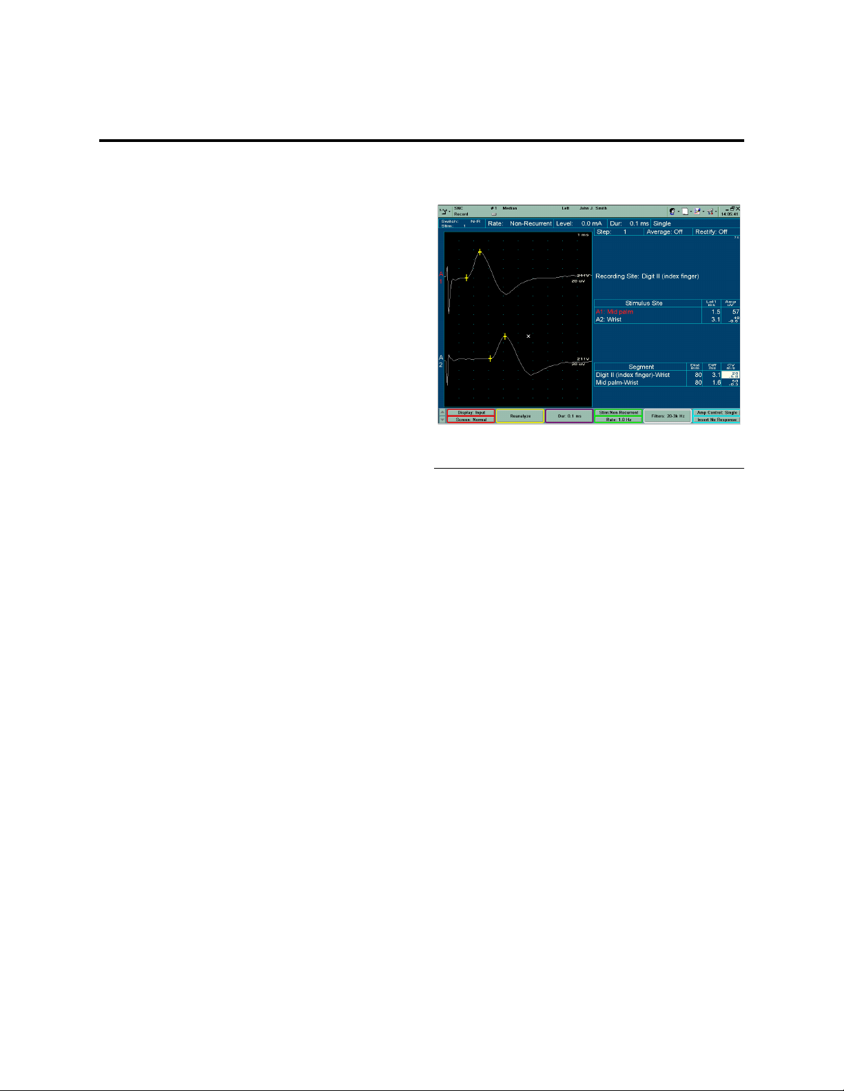
Chapter 2
System Overview
Sample Patient Data Screen
Revision 3/06/01 2 - 1
Page 16
VikingSelect Service Manual
VikingSelect Block Description
This section describes the VikingSelect at the block
level. The order of topics is:
1. Power and Power Distribution
2. Computer Platform
3. Patient Signal Path
4. Software
Power Distribution
The power supply and power distribution system for the
Endeavor contains the following components:
• isolated power supply
• computer power supply
• FireWire Isobox
• FireBrick
Sky Link Buses
Headphones
or other
Auditory
Transducers
Power Link Bus:
+15V
-15V
AGND
Stim Link Bus:
STIM1STIM2-
DGND
1MHz CLK
Computer Platform
The System Controller is an Juneau-type, 550 MHz,
Intel Pentium III plat form with 1 28MB of sy stem RAM.
The 8.6GB (or larger) is partitioned with 2GB as the C:\
drive for the operating system and the remaining space
for patient data and Viking settings.
The following boards plug into the System Controller
expansion slots:
• Electrical Stim Board • Auditory Stim Board
• D-Stim Board • Firewire Interface
Board
Input/output devices that connect directly to the
computer are the keyboard, mouse and printer. The
mouse connects to the COM1 serial port, keyboard to
the keyboard port and the printer to the parallel port.
continued on next page
Internal
FireWire
To
Network
Current Probe
with IES Box
Footswitch
Control
Panel
Speaker
Trigger 1 Out
(2015 Visual Stimulator)
Trigger 2 Out
Goggles
Ganzfeld
Trigger In
NIC Auditory
1
%
S403
IES403-1
Stimulator
Breakout
Box
Board
NIC Electrical
Stimulator
Board
ISA
NIC D-Stim
I/O Board
ISA
ISA
Network
Interface
Board
FireWire
FireWire
(Power Added
From Iso Box)
AnalogOut
A
B
Amplifier
(ES-4, ES-8 or EA-2)
CPU
Power
Supply
5V,
12V
PCI
Isolation
Box
Amplifier
Keyboard
FireWire
Interface
Board (1394)
PCI
CPU Buses
CPU
Motherboard
Floppy
Hard
CD Rom
Drives
AGP
Graphics
Display Board
AGP
Flat Panel
Monitor
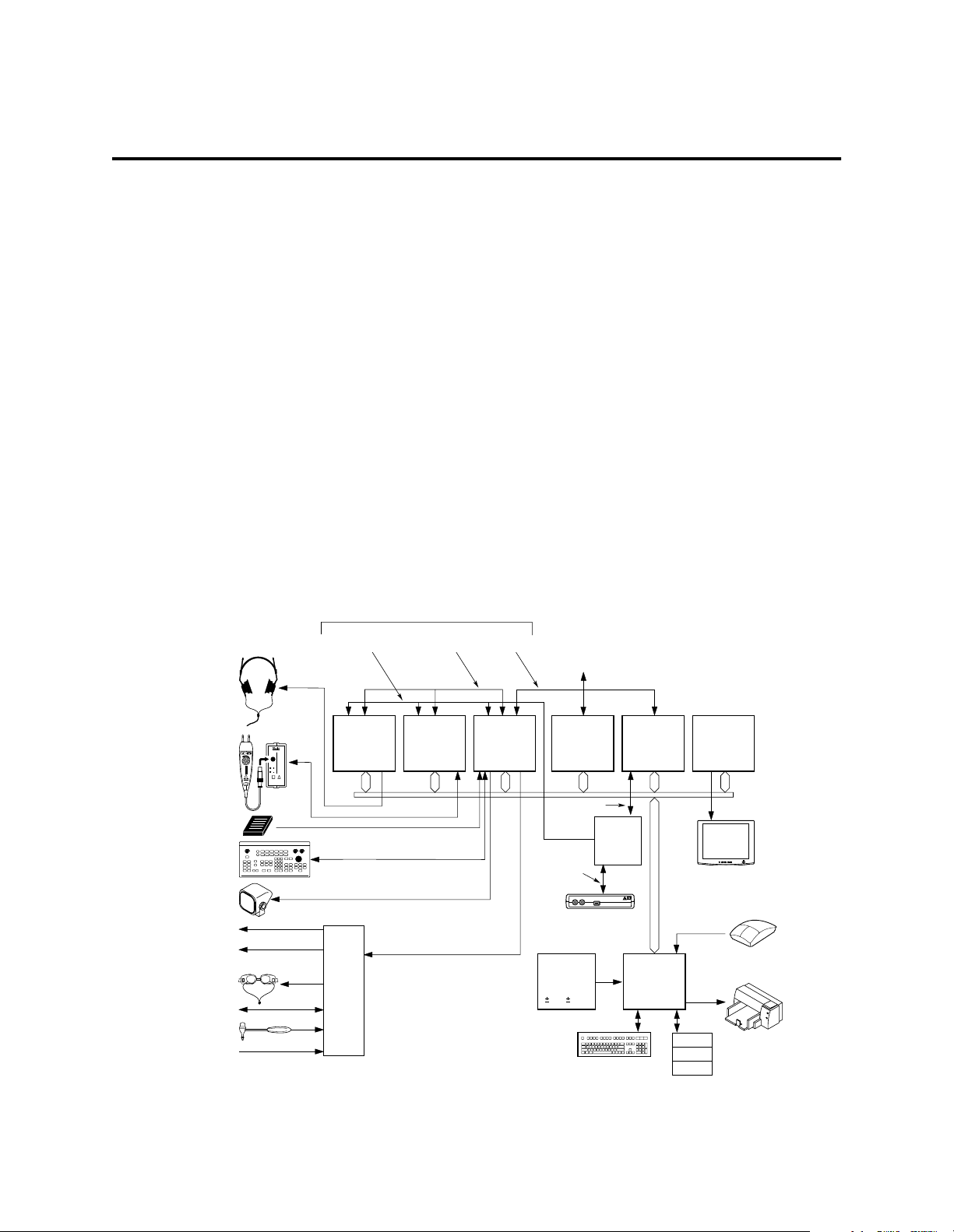
Mouse
Printer
VikingSelect Acquisition Station Components
2 - 2 Revision 3/06/01
Page 17

Printer
Nicolet sells and supports the following printers:
• HP DeskJet
• Okidata Laser Printer
System Overview
Revision 3/06/01 2 - 3
Page 18
VikingSelect Service Manual
Patient Signal Path Components
Video Path Components
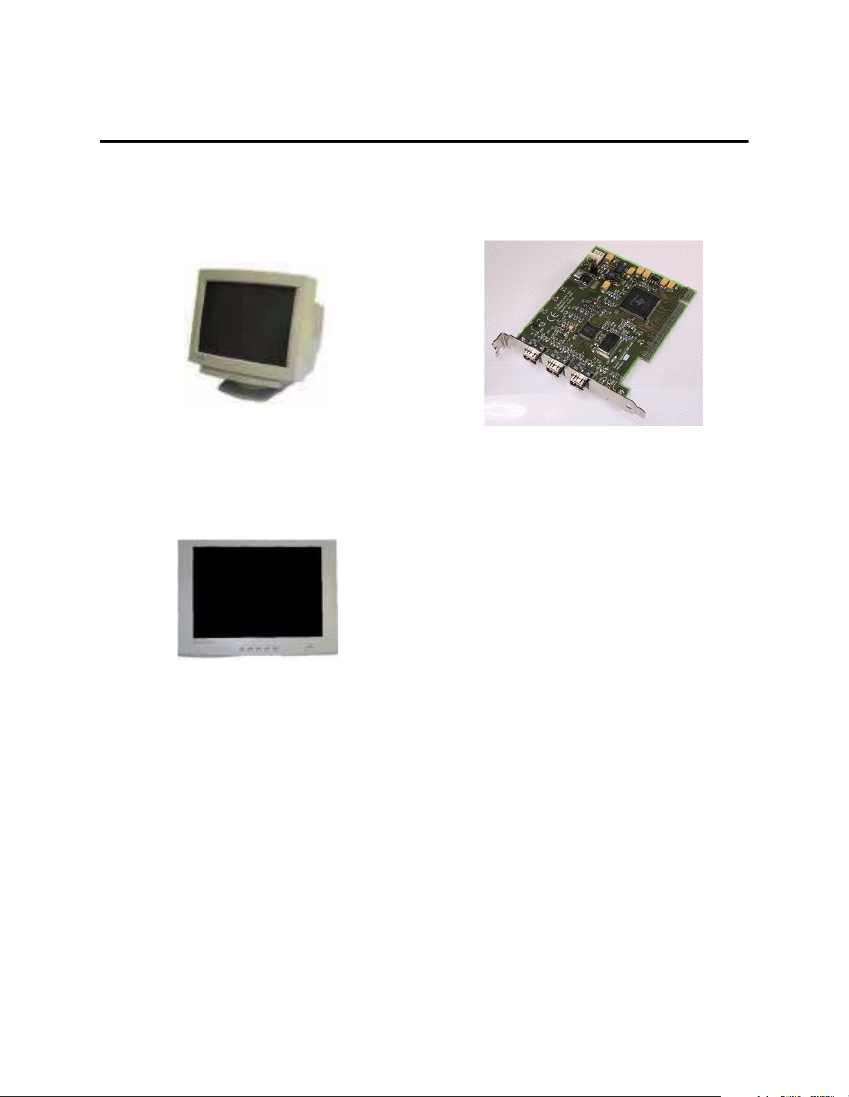
Monitor
The user has a choice of high resolution EEG monitors:
17-inch or 19-inch. Both monitors display data at a
resolution of 1024 x 768 pixels.
The VikingSelect can be also obtained with either a 15-
inch or 18-inch flat panel display.
Networking
Networking on the VikingSelect is accomplished by
integrating the network card into the Intel PIII
motherboard.
FireWire Card
FireWire is a cross-platform implementation of the
high-speed serial data bus, as defined b y I EEE Stan dard
1394-1995, that can move large amounts of data
between computers and peripheral devices. It features
simplified cabling, hot s wapping, and transfer speeds o f
up to 400 megabits per second.
FireWire supports two types of data transfer:
asynchronous and isochronous. Traditional computer
memory-mapped, load and store applications makes
asynchronous transfer appropriate and adequate.
One of FireWire’s key features is its support of
isochronous data channels. Isochronous data transfer
provides guaranteed data transport at a pre-determined
rate. This is especially important for multimedia
applications where uninterrupted transport of timecritical data and just-in-time delivery reduce the need
for costly buffering.
continued on next page
2 - 4 Revision 3/06/01
Page 19
System Overview
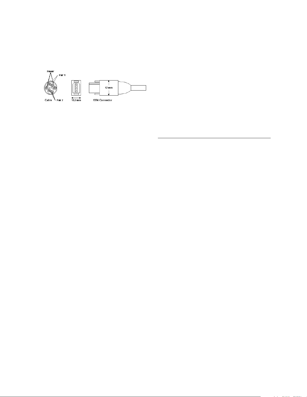
FireWire Cabling
The fire wire cables are made with a 6-conductor cable
containing two separately-shielded twisted pair
transmission lines for signaling, two power cond uctors,
and an overall shield. The two twisted pairs are crossed
in each cable assembly to create a transmit-receive
connection. The power conductors supply power at 8 to
40 V, 1.5 a max.
Stimulators
The VikingSelect uses various stimulators and
stimulator components. These are:
• Electrical:
- 1 or 2-Channel Current Board
- IES 405-1 or 405-2 with S403 Current Probe
- IES D-9 with S403 Current Probe
• Auditory:
- Auditory Stim Board
- Shielded and unshielded TDH-39 Headphones
- TIP 300 Tubal Inserts
- Bone Vibrator
• Visual Stimulator:
- 1015 and 2015 Pattern Reversal
- LED Goggles
- Photic Strobe
- Ganzfeld Sti mulator
Software
The VikingSelect is a Windows NT-based system
running Electromyography (EMG) application software.
Status event detection software is an option. Other
software may be installed based on the options in the
system. The following list defines the software packages
found in the acquisition station.
• MS Windows NT Workstation 4.0
• NicVue patient administrator
• VikingSelect application
• Diskeeper Lite
• Adaptec DirectCD
• Microsoft Word
Revision 3/06/01 2 - 5
Page 20

VikingSelect Service Manual
Blank Page
2 - 6 Revision 3/06/01
Page 21

Software Overview
Chapter 3
Software
The VikingSelect Acquisition system provides the user
with the software necessary to perform various
neurodiagnostic testing on a patient. The VikingSelect
Acquisition system software consists of:
• VikingSelect Master Software
• VikingSelect Applications
• NecVue Patient Administration Database
• Microsoft Windows NT Operating System
• Microsoft Word 2000 (if Report MSW is installed)
The VikingSelect software is loaded on the Microsoft
Windows NT operating sys tem. The operating system
provides an interface between the applications loaded
onto the system and the hardware platform. The
VikingSelect software must be installed on the NT
operating system to properly function.
The function of the VikingSelect application is to
provide the user with an interface to perform Nerve
Conduction, Electromyography and Evoked Potential
studies on a patient. The VikingSelect can also print a
summary of the test results with the optional Rep ort
MSW software. The Report MSW option includes the
templates and sub-reports to collect the informationfrom
the patient tests. The information is collected from the
exams performed on the patient and summarized on a
®
Word
The NicVue Patient Administration Database is a
common interface for all Nicolet Biomedical Products.
NicVue providesa common interface to enter patient
information, tracking patient data file locations, and a
method to launch various Nicolet Biomedical
applications. NicVue is the s tarting poi nt for perf orming
an exam, reviewing an exam, or scheduling an
appointment.
2000 document.
This section describes:
Topic Page
Administrative Tools 3-2
NT Software Load - Juneau 3-5
Diagnostics 3-19
FW Host 3-22
System software is preloaded and system tested at the
factory before delivery. System symptoms, however,
may require that some or all software be reloaded. As
improvements are made, it may be necessary to install
software patches and upgrades.
continued on next page
Revision 3/23/01 3 - 1
Page 22
VikingSelect Service Manual
Partitions & File Systems
Acquisition Station
The VikingSelect Acquisition Station contains one
8.6GB (or larger) hard drive configured as a volume set
with two partitions, C: and D:. C: is the active boot
partition. This two gigabyte FAT 16 partition contains
the NT system files, Nicolet applications and all
program files. The remaining space is assigned drive
letter D: and formatted as NTFS for large drive support
and more efficient storing capabilities. Drive D: is used
for data storage only; no program or sy stem file s shou ld
reside on this partition.
NTFS vs. FAT
Feature NTFS FAT
Long File Names Yes Yes*
Support Multiple
File Forks for
Macintosh Files
Log Structured
For Fault Tolerance
Large Partitions Yes No
Hot Fixing Yes No
File Level Com-
pression
*DOS will only support 8.3 files naming convention
Yes No
Yes No
Yes No
Administrative Tools
This section describes the Windows NT administrative
tools available to you as an Administrator.
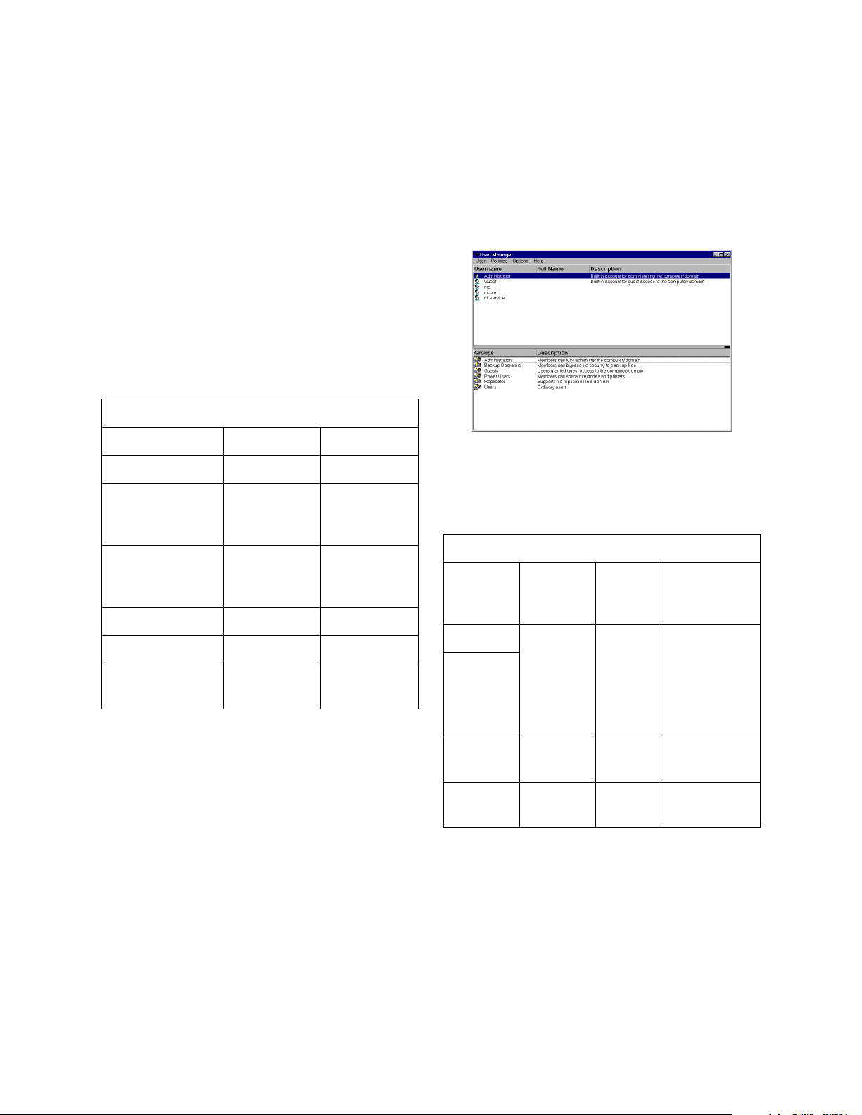
User Manager
The User Manager utility allows you to create, modify
and delete user accounts.
Standard Nicolet Accounts
Account
User
Name
Nicolet None AdminNic
Administrator
Password Group Policies
User can
istrator
nicolet Admin-
istrator
change display properties, settings
not saved
upon exit.
None
NicService
All Nicolet default users are Administrators. The reason
all users are in the Administrators group is because the
VikingSelect software r equires administrat ive privileges
to function. If new users are added to the system for any
reason, they should be assigned to the Administrators
group.
service Admin-
istrator
continued on next page
None
3 - 2 Revision 3/23/01
Page 23
Software
Adding a new account
In most cases additional accounts are unnecessary.
However, if a doctor wants to review data from the
acquisition system on his personal desktop, and the
computers are on the same network, he should have a
user account that matches his logon on his PC.
Step Action Response
1. Click on Start/Pro-
grams/Administrative T ools /User
Manager.
2. Highlight Nic, Nico-
let or Administrator,
depending on the
level of control you
want user to have.
Press the F8 key.
3. Add the same user-
name and password
as the doctor is currently using for their
PC. Make sure the
only option that is
checked is Password never expires.
4. Click OK. The new user is cre-
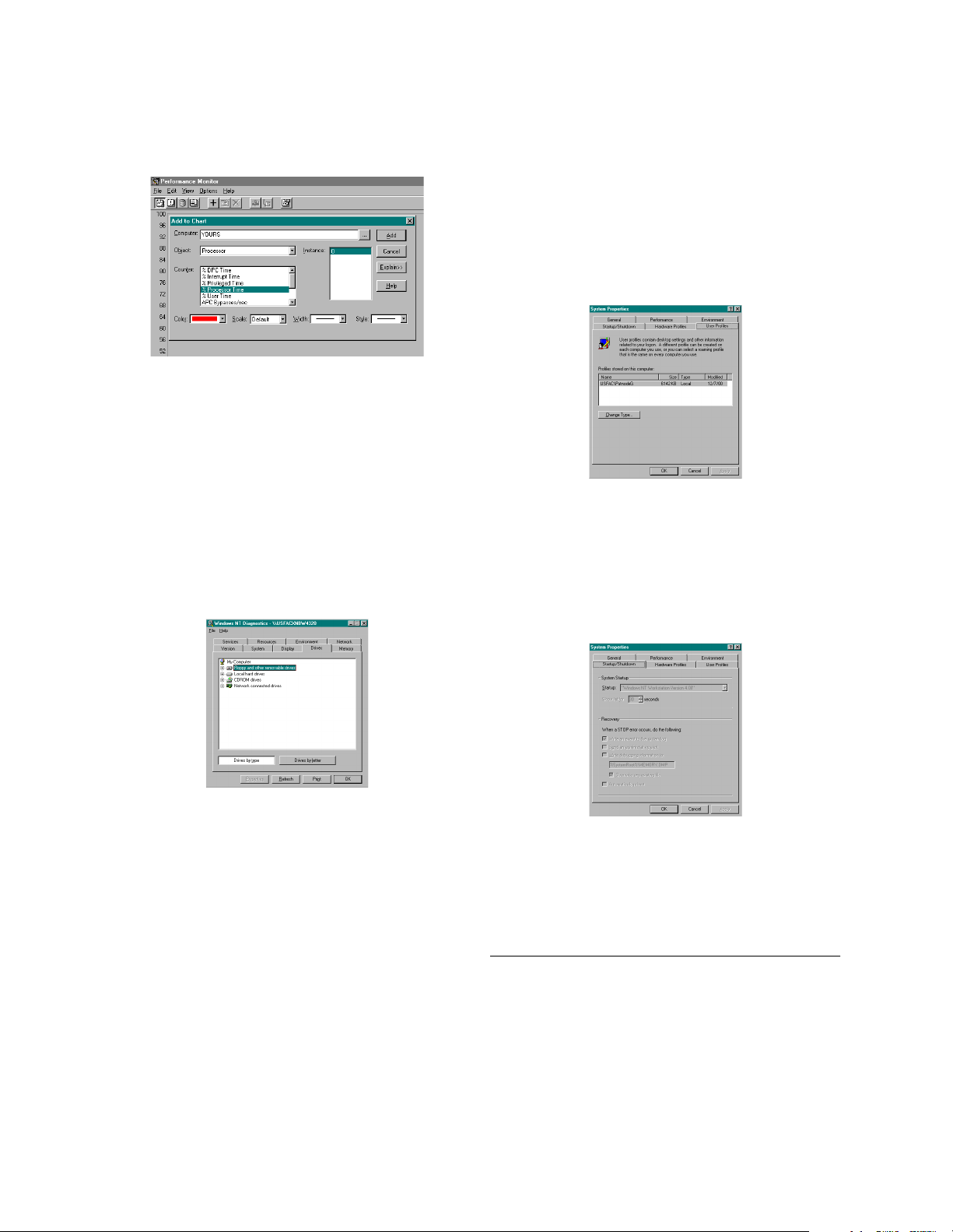
Disk Administrator
The User Manager
utility opens.
The system copies
the highlighted user
account and opens a
Local Group Properties window.
- - -
ated.
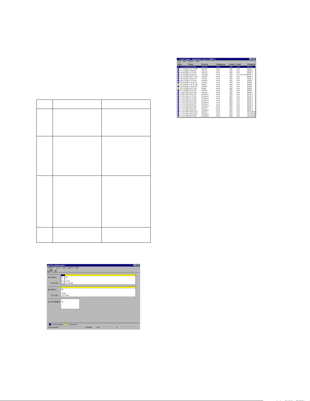
Event Viewer
This is one of the Administrative Tools available to all
users. The event viewer will display additional
information on all Windows error messages that occur
while using the system. Event Viewer is separated into 3
different sections, System, Security and Application.
Each log can be accessed through the File menu.
The System log displays all messages regarding system
errors, information and service status. This will be the
most commonly used log. When a message appears at
boot up that a service has failed to start look in the
System log to see which one. Services are often
dependent on each other so if 1 service doesn’t start it
may prevent a number of other services from not
starting. Any service that has an error will be listed in
the System log with the appropriate time stamp.
The Security log is not utilized by default. If security
logging is enabled failed and/or successful logon
attempts will be displayed as dictated by the user.
Security logging can be setup in User Manager. There is
not usually a practical reason for enabling security
logging for most Nicolet networks.
The Application log records errors generated by nonoperating system applications. If a Nicolet application
crashes, a Dr. Watson message appears and an entry is
generated in the Application log.
continued on next page
Disk Administrator can be used to view, add or change
partition information. This utility should only be used
after reinstalling the operating system or when adding or
removing a physical drive.
Revision 3/23/01 3 - 3
Page 24
VikingSelect Service Manual
Performance Monitor
This utility will not be used very often, if ever. Only
when items such as process threads, interrupts, hard disk
caching, or network requests are suspected to be causing
a problem should Performance Monitor be used. Items
can be monitored by pressing the plus button on the
toolbar. You can then select any number of possible
items to monitor. Keep in mind that Performance
Monitor uses resources itself and will skew your results
slightly. Task manager is a better utility when basic
processor, and memory information is needed.
Windows NT Diagnostics
Other Administrative Tools
Backup and Remote Access Administration are also
included in Administrative Tools. Neither one of these
options is used because the accompanying hardware,
(tape drive and/or modem) are not available through
Nicolet at this time.
Other Windows NT Properties
Right click on My Computer and select Properties to
view the System Properties and add new user profiles.
continued on next page
Changing the startup boot menu
Just before Nicolet ships a system we copy its
configuration to a text file and save this file on a
Customer Support Server. This text file is created using
Windows NT Di agnostics (MSD). MSD displays a
number of registry entries in an organized graphical
manner. This includes all of the system resources, hard
disk utilization, memory allocation, page file sizes,
graphics card specifications and other configuration
information. NT Diagnostics is a viewer only; items can
not be changed in this utility. You have the option to
print this information to a printer or text file. You may
be asked to copy this info to a file for comparison to the
shipping configuration MSD report. The diagnostics
report gives us an idea if the user has modified, added or
deleted anything on the system. Diagnostics is av ailable
to all users.
Choose the Startup/Shutdown tab. You can change the
amount of time the system waits for you to make a
selection. 0 seconds will not display a menu and
automatically boots the default selection, which is set in
the Startup: field boots to this tab.
3 - 4 Revision 3/23/01
Page 25

NT Software Load - Juneau
Software
This procedure is used to install Windows NT and
Viking software on a new hard drive. This is not part of
the normal software install procedure. Performing this
procedure results in the loss of all data stored on the
C: and D: partitions.
Software required:
482-6275xx Recovery Image Boot disk
482-6280xx System NT Image CD
482-6259xx NicVue Install CD
482-1138xx VikingSelect Addendum CD
482-1139xx VikingSelect Software License Disk
222-446300 Microsoft Office 2000 Small Busi-
ness edition (only if report MSW is
to be installed)
Information required:
• Windows NT software license number.
• The system serial number and system name.
• The customer name and company name.
• If the system is networked, you will also need the
TCP/IP address and Subnet Mask. See your system
administrator for this information.
Initial System Sof twa re Load
This procedure is separated into seven sections:
1. Deleting Partitions
2. Reloading Windows NT Operating system
3. Configuring Windows for your system
4. Create and configure the D-drive partition
5. Install Microsoft Word (if report MSW option is
installed)
6. Install NicVue software
7. Install VikingSelect software
Important:
If all required software is not present, do not
attempt to perform this procedure.
continued on next page
Revision 3/23/01 3 - 5
Page 26

VikingSelect Service Manual
Deleting Partitions
DELETING PARTITION INFORMATION WILL
CAUSE ALL DATA TO BE LOST. THE INITIAL
SYSTEM LOAD PROCEDURE EXPECTS THE
HARD DRIVE TO NOT HAVE A PARTITION. IF
THERE IS A PARTITION ON THE HARD DRIVE,
THIS PROCEDURE WILL NOT WORK.
Step Action
1. Place the Recovery Image Boot Disk, part
number 482-6275xx, into floppy drive and
reboot the system.
2. Press F5 when the DOS menu screen
appears.
3. Type in FDISK, press [Enter] and select 4
(display the partition information).
NOTE:
Note the type of partition and press ESC.
4. Select 3 (delete partition) and select the cor-
responding type of partition to delete. Verify that it is highlighted and type Y to delete
it.
5. Repeat step 4 for any and all remaining par-
titions.
6. Press ESC three times to restart the com-
puter.
continued on next page
3 - 6 Revision 3/23/01
Page 27

Loading Windows NT Configuring Windows NT
Software
Step Action
1. Boot the system to the Recovery Image
Boot Disk, part number 482 -6275xx. When
you see the MS DOS Startup Menu, Insert
the System NT Image CD, Part number
482-62800x into the CD drive.
2. Type 1 on the MS-DOS 6.22 Startup menu
to select Detect Hardware and press
[Enter]. After displaying a few messages,
the system will reboot.
3. Type 2 on the MS-DOS 6.22 Startup Menu
to select Load/Recover Operating System
Options and press Enter. After displaying a
few messages, the screen displays the option
menu.
4. Type 1 to sel ect Initial System Load For
System NT Systems and press [Enter]. The
system enters the Easy Restore Utility. The
system displays a progress r epor t durin g the
Windows NT Restore process.
5. When NT is restored, the system displays a
message advising you to reb oot the sy stem.
Remove the floppy disk from the floppy
drive, then click on the Reboot button.
6. The system may display a Service Control
Manager message alerting you that at least
one service or driver failed during system
startup. Click on OK, if you see this message.
7. Press Ctrl+Alt+Del to get the login screen
and log on as Administrator and type nicolet
as the password.
Step Action
1. First, delete the SCSI drivers. On the Win-
dows NT desktop, select <Start > Settings
>Control Panel. Double-click on the SCSI
Devices icon on the Control Panel window.
Click on the Drivers tab on the SCSI adapters window.
2. Highlight the Adaptec AHA-294X/AHA394X or AIC-78XXPCI SCSI… option,
then click on Remove. Click on Yes to confirm that you want to remove this driver.
Click on OK to close the window.
3. Next, update the Adaptec software to recognize the HP9300 CD-R/R W driv e. The Sys tem Image CD should still be in the CDDrive.
4. Right click on the My Computer icon on
the desktop and select Explore.
5. Click on the + sign in front of the E-Drive
(E:).
6. Double-click on the Drivers folder
7. Double-click on the Direct CD3_0 folder
and Double-click on the file call ed Update.
This will install an update to the Adaptec
software.
8. Click on Update and when load is completed, click on Yes to reboot the computer.
9. When the system reboots, log on as administrator and type Nicolet as the password.
Verify that no Service Control Manager
alerts are displayed.
continued on next page
Revision 3/23/01 3 - 7
Page 28

VikingSelect Service Manual
D-drive Configuration Installing Microsoft Word 2000
Step Action
1. Click on <Start> <Programs> <Administrative Tools (common) > <Disk Administrator>. An information box will appear
informing you that this is the first time Disk
Administrator has been run, click on OK to
continue.
2. Right-click on the area to the right of the C :
drive box labeled "Free Space" and select
Create. When asked to confirm the creation
of the new partition, click on Yes. Verify
that the maximum partition size is shown in
the edit box and click OK.
3. Right-click on the new partition and select
Commit Changes Now. When asked to
confirm, click on YES to save the changes,
and then click on OK to acknowledge the
new changes.
4. Right-click on the new partition again and
select Assign Drive Letter. Select drive letter D and click on OK to confirm.
5. Right-click on the new partition again and
select Format. Under the File System edit
box, make sure that NTFS is shown and
place a check mark in the Quick Format
box before clicking the Start button. Click
on OK at the warning box and wait for the
format to complete.
6. When formatting is complete, click on OK
and then click on Close to remove the window. Close Disk Administrator window.
NOTE:
Microsoft Word 2000 must be installed and properly
configured for the Report MSW package to function
properly. If the VikingSelect system does not have the
MSW Report software package proceed to the next
section.
Step Action
1. Properly close all Windows applications, if
any are open.
2. Log on as administrator and type nicolet as
the password.
3. Insert the CD labele d "Microsoft Office
2000, Small Business, Disc 1," into the CD
drive. The setup program should start running automatically. You will see the message, "Preparing to install Microsoft Office
2000 Small Business," then the Welcome
screen.
4. If the program does not start automatically,
follow steps a-b below:
a. Select <Start> <Run>.
b. On the Run box, type the drive letter
(E:\) for the CD drive, then type setup
and click on OK (e:\setup).
5. On the Welcome screen, type the 25-charac-
ter Product ID. This number is located on
the cover of your Discovering Microsoft
Office 2000 manual. Click on Next.
6. On the Ready to Install window, click on
Customize.
7. On the Installation Location window, check
that the destination drive is C:\Program
Files\Microsoft Office, then, click on Next.
8. On the Upgrade Windows NT Explorer 5.0,
click on the drop down box (the arrow on
the center right side of the window), then
click on Do Not Upgrade Microsoft Internet
Explorer, then click on Next.
continued on next page
3 - 8 Revision 3/23/01
Page 29

Software
Step Action
9. On the Select Features window, click on the
+ sign in front of Microsoft Word for Windows to display the Word options.
10. Click on the icon in front of the following
options for Microsoft Word for Windows:
a. Help, then select Run from My Com-
puter.
b. Wizards and Templates, then select Run
from My Computer.
c. Text with layout Converter, then select
Run from My Computer.
11. Click on the - sign in front of Microsoft
Word for Windows to close the Word
options list.
12. Click on the + sign in front of Office Tools
to display the Office Tools options.
13. Click on the icon in front of the following
option for Microsoft Word for Windows.
14. Office Assistant, then select Run from My
Computer.
15. Click on the + sign in front of Proofing
Tools to display the Proofing Tools optio ns .
16. Click on the icon in front of the following
options:
Step Action
20. Click on the icon in front of the following
options:
• Microsoft Excel for Windows, then
select Not Available.
• Microsoft Outlook for Windows, then
select Not Available.
Setup places a red "X" in front of these
options.
21. Click on Install Now. A progress report is
displayed as the installation proceeds. This
custom installation takes about 5 minutes,
so please be patient.
22. When the installation setup is complete, you
will see the Installer Information window
with a message stating you must restart your
system. Click on Yes to restart the system.
23. Log on as administrator and type nicolet as
the password.
24. After restarting the system, the installation
continues. Do Not cancel any of the in stallation messages. When the installation is
complete, click on OK.
25. Remove the Microsoft Office 2000, Small
Business, Disc 1," CD from the CD drive
and store with your other Viking and NicVue installation CDs.
a. Spelling Checker, then select Run from
My Computer.
b. Grammar/Style Checker, then select
Run from My Computer.
c. Thesaurus, then select Run from My
Computer.
17. Click on the - sign in front of Proofing
Tools to close the Proofing Tools options
list.
18. Click on the - sign in front of Office Tools
to close the Office Tools options list.
19. Click on Converters and Filters, then select
Run from My Computer.
Revision 3/23/01 3 - 9
Page 30

VikingSelect Service Manual
Installing NicVue Software Installing VikingSelect Master &
Application Software
Step Action
1. If you rebooted the s ystem after co nfiguring
it, be sure t o log on as ad ministrator and
type nicolet as the password before loading
NicVue software.
2. Insert the NicVue Installation CD into the
CD drive. If it does not start, follow these
steps:
a. Select <Start><Run>.
b. On the Run box, type the drive letter for
the CD drive.
c. Click on the Browse button.
d. Next, double-click on the run folder.
e. Click on autorun (autorun.exe) and OK.
3. Read the information given on the NicVue
V2.0 Welcome screen, then click on Next.
4. Read the Software License Agreement, then
click on Yes to begin installing the NicVue
software.
5. Click on Yes when you see the following
message. “Do you want NicVue to startup
automatically each time you start the computer?”
6. After the software is installed, select Yes, I
want to restart my computer no w option .
7. Click on Finish.
8. Remove the NicVue CD from the CD drive.
Step Action
1. Make sure you are logged in as administra-
tor and no other programs are running.
Insert the VikingSelect Addendum CD
(482-1138xx) in the CD drive. The setup
program should start up automatically. If it
does not start, follow the steps below:
a. Select <Start> <Run>.
b. On the Run box, type the drive letter for
the CD drive.
c. Click on the Browse button.
d. Next, Double-click on the run folder.
e. Click on autorun (autorun.exe) and OK.
2. Read the information given on the VikingSelect Welcome screen, then click on Next.
3. Read the Software License Agreement, then
click on Yes.
4. Select the type of VikingSelect system you
have (VikingSelect Acquisition System),
then click on Next.
5. On the menu box, select the following
options:
[X] Install Master Software
[X] Install License Software
[X] Install Settings (If the customer has a
backup of custom settings they can be
reloaded later).
6. When finished, Click Next.
7. On the Software Registration box, type the
Viking system serial number, located on
right side of the processor, and press Enter.
8. Verify that the number you typed matches
the number listed on the box and on the
license disk. If yes, click on Next. If no,
click on Back and enter the correct number.
continued on next page
3 - 10 Revision 3/23/01
Page 31

Software
Completing Report MSW Install
Step Action
9. Insert the VikingSelect Software License
disk into the floppy drive and clic k on Next.
Because you selected Install Settings in Step
5, on the Select Settings window, select all
the application settings you wish to install.
10. If you selected the Install Report Settings
option on the previous screen and have purchased the VikingSelect Report MSW program you will select the Report Templates
next. Click on all the options you wish to
install.
11. Click Start to begin installing the VikingSe-
lect NT software.
12. When the VikingSelect Program files are
installed, the setup program displays the
Microsoft Data Access V2.1 License Agreement window. Read the agreement, then
click on Yes to continue.
13. After displaying several system messages,
the screen displays the Microsoft Data
Access 2.1 setup window. Read the information given on the Microsoft Data Access
2.1 Setup window, then click on Continue.
14. The screen displays the Start Installation
Setup window. Click on the large button on
the center left side of the window to begin
the installation. Do not click on the Exit
Setup button.
15. When you see the message, "Microsoft Data
Access 2.1 setup was completed successfully", click on OK to continue. If you s ee a
message asking you to restart the system,
click on OK to continue.
16. When the Viking Select installation is com-
pleted, the program displays the setup complete window. Remove the VikingSelect
Software License disk and the Addendum
CD from the drives.
17. Click on Yes, I want to restart my computer now then click on Finish. The sys-
tem will restart.
18. Enter the appropriate logon information.
NOTE:
This portion of the instal lation n eeds to be complete d on
systems with Report MSW only. Report MSW will not
function until the following steps have been completed.
Step Action
1. Enter the VikingSelect Program, by clicking
a Vi king S elect icon on the NicVue icon bar.
2. Press the Report button on the control panel.
3. Because the Report MSW Program contains
some additions and modifications to the
W ord 200 0 Program, the firs t time you open
the Report MSW Program, you will see a
warning message about the macros.
4. This W ord 20 00 startup message is meant to
protect the computer from a potential macro
virus infection. Be assured that the Report
MSW Program is free of any macro virus.
Click on OK to continue. Also, the first time
you open the newly instal led Word 2000, an
End User Agreement box is displayed.
Click on Accept to continue.
5. On the Word Menu bar, click on <Tools>
<Customize>...
6. On the Options window, click once on the
following two options to deselect them.
Standard and Formatting toolbars share one
row.
Menus show recently used commands first
(Deselecting this option displays the complete list of options on the Word pull-down
menus, rather than just an abbreviated list.)
7. Click on Close.
8. Close the Control toolbox by deselecting it
(<View><Toolbars><Control Toolbox>.
9. Display the Office Assistant for quick
access to online help (<Help><Show the
Office Assistant>).
continued on next page
Revision 3/23/01 3 - 11
Page 32

VikingSelect Service Manual
Step Action
10. Perform these steps to activate the Report
MSW macros.
11. On the Word Menu bar, click on
<Tools><Macro><Security>...
12. On the Security Level window, click on
Low.
13. Click on OK.
14. Exit Microsoft Word (<File><Exit>), then
reopen the program from the VikingSelect
Program by pressing the Report key on the
control panel.
15. Verify the report software now functions
properly.
3 - 12 Revision 3/23/01
Page 33

Software
Image Recovery Procedure
This procedure attempts to recover the C: partition
while leaving the D: partition unaffected. This is useful
because the patient data and VikingSelect setting files
are located on the D: partition. When reloading any
software it is important to back up patient and setting
files prior to this procedure if it is at all possible.
This procedure is separated into six sections:
1. Reload Windows NT Operating system
2. Unhide the NTFS Partition
3. Configure Windows for your system
4. Install Microsoft Word (if report MSW option is
installed)
5. Install NicVue software
6. Install VikingSelect software
Important:
If all required software is not present, do not
attempt to perform this procedure.
Software required:
482-6275xx Recovery Image Boot disk
Reloading the Windows NT Operating System
Step Action
1. Boot the system to the Recovery Image
Boot Disk, part n umber 4 82- 6275x x. W hen
you see the MS DOS Startup Menu, insert
the System Image CD, part number 4826280xx, into the CD drive.
2. Type 1 on the MS-DOS Startup Menu to
select Detect Hardware and press Enter.
After displaying a few messages, the system
will reboot
3. Type 2 on the MS-DOS Startup Menu to
select Load/Recover Operating System
Options and press Enter.
4. Type 2 on the MS-DOS Startup Menu to
select Repair/Update Existing System Box
with NT and press Enter. The system
enters the Easy Restore Utility and displays
a progress report during the Windows NT
restore process.
5. When the operating system is restored, the
system displays a message advising you to
remove the floppy disk and to reboot the
system. Leave the Recovery Image Boot
Disk, part number 482-6275xx, in the
floppy drive and press the Reboot button.
482-6280xx System NT Image CD
482-6259xx NicVue Install CD
482-1138xx VikingSelect Addendum CD
482-1139xx VikingSelect Software License
Disk
222-446300 Microsoft Office 2000 Small
Business edition
(only if report MSW is to be
installed
Information required:
• Windows NT software license number.
• The system serial number and system name.
• The customer name and company name.
• If the system is networked, you will also need the
TCP/IP address and Subnet Mask. See your system
administrator for this information.
Revision 3/23/01 3 - 13
continued on next page
Page 34

VikingSelect Service Manual
Unhide the NTFS Partition
If you are at a login screen then you failed to f ollow step
5 in the previous section. Reinsert the Recovery Image
Boot Disk, part number 482 -6275x x, in the fl oppy drive
and reboot the system.
Step Action
1. When the system boots, the MS-DOS Star-
tup Menu is displayed. Type 3 to select
Unhide NTFS Partition and p ress Enter.
2. The system will display several messages
and reboot. Remove the Recover Image
Boot Disk when the system reboots and
allow the system to boot to the Windows NT
Begin Logon screen.
3. The system may display a Service Control
Manager message alerting you that at least
one service or driver failed during system
startup. Click on OK, if you see this mes-
sage.
4. Press Ctrl+Alt+Del to get the login screen
and log on as Administrator and type nicolet
as the password.
Step Action
5. Click on the + sign in front of the E-Drive
(E:).
6. Double-click on the Drivers folder
7. Double-click on the Direct CD3_0 folder
and Double-click on the file call ed Update.
This will install an update to the Adaptec
software.
8. Click on Update and when load is completed, click on yes to reboot the computer.
9. When the system reboots, log on as administrator and type nicolet as the password.
Verify that no Service Control Manager
alerts are displayed.
Installing Microsoft Word 200 0
NOTE:
Microsoft Word 2000 must be install and properly
configured for the Report MSW package to function
properly. If the VikingSelect system does not have the
MSW Report software package proceed to the next
section.
Configuring Windows NT
Step Action
1. First, delete the SCSI drivers. On the Win-
dows NT deskt op, select Start >Settings
>Control Panel. Double-click on the SCSI
Devices icon on the Control Panel window.
Click on the Drivers tab on the SCSI adapt-
ers window.
2. Highlight the Adaptec AHA-294X/AHA394X or AIC-78XXPCI SCSI… option,
then click on Remove. Click on Yes to confirm that you want to remove this driver.
Click on OK to close the window.
3. Next, update the Adaptec software to recognize the HP9300 CD-R/R W driv e. The System Image CD should still be in the CDDrive.
4. Right click on the My Computer icon on
the desktop and select Explore.
Step Action
1. Properly close all Windows applications, if
any are open.
2. Log on as administrator and type nicolet as
the password.
3. Insert the CD labele d "Microsoft Office
2000, Small Business, Disc 1," into the CD
drive. The setup program should start running automatically. You will see the message, "Preparing to install Microsoft Office
2000 Small Business," then the Welcome
screen.
4. If the program does not start automatically,
follow steps a-b below:
a. Select Start > Run.
continued on next page
3 - 14 Revision 3/23/01
Page 35

Software
Step Action
b. On the Run box, type the drive letter
(E:\) for the CD drive, then type setup
(e:\setup) and click on OK.
5. On the Welcome screen, type the 25-character Product ID. This number is located on
the cover of your Discovering Microsoft
Office 2000 manual. Click on Next.
6. On the Ready to Install window, click on
Customize.
7. On the Installation Location window, check
that the destination drive is C:\Program
Files\Microsoft Office, then, click on Next.
8. On the Upgrade Windows NT Explorer 5.0,
click on the drop down box (the arrow on
the center right side of the window), then
click on Do Not Upgrade Microsoft Inter-
net Explorer, then click on Next.
9. On the Select Features window, click on the
+ sign in front of Microsoft Word for Win-
dows to display the Word options.
10. Click on the icon in front of the following
options for Microsoft W ord for Windows:
a. Help, then select Run from My Com-
puter.
b. Wizards and Templates, then select
Run from My Computer.
c. Text with layout Converter, then select
Run from My Computer.
11. Click on the - sign in front of Microsoft
Word for Windows to close the Word
options list.
12. Click on the + sign in front of Office Tools
to display the Office Tools options.
13. Click on the icon in front of the following
option for Microsoft Word for Windows:
Office Assistant, then select Run from My
Computer.
14. Click on the + sign in front of Proofing
Tools to display the Proofing Tools optio ns .
Step Action
15. Click on the icon in front of the following
options:
a. Spelling Checker, then sel ect Run from
My Computer.
b. Grammar/Style Checker, then select
Run from My Computer.
c. Thesaurus, then select Run from My
Computer.
16. Click on the - sign in front of Proofing
Tools to close the Proofin g Tools options
list.
17. Click on the - sign in front of Office Tools
to close the Office Tools options list.
18. Click on Converters and Filters, then
select Run from My Computer.
19. Click on the icon in front of the following
options:
• Microsoft Excel for Windows, then
select Not Available.
• Microsoft Outlook for Windows, then
select Not Available.
Setup places a red "X" in front of these
options.
20. Click on Install Now. A progress report is
displayed as the installation proceeds. This
custom installation takes about 5 minutes,
so please be patient.
21. When the installation setup is complete, you
will see the Installer Information window
with a message stating you must restart your
system. Click on Yes t o re start the system.
22. Log on as administrator and type “nicolet”
as the password.
23. After restarting the system, the installation
continues. Do Not cancel any of the installation messages. When the installation is
complete, click on OK.
continued on next page
Revision 3/23/01 3 - 15
Page 36

VikingSelect Service Manual
Step Action
24. Remove the Microsoft Office 2000, Small
Business, Disc 1," CD from the CD drive
and store with your other Viking and NicVue installation CDs.
Installing NicVue software.
Installing the VikingSelect Master and Application Software.
NOTE:
Make sure you are logged in as administrator and no
other programs are running. Insert the VikingSelect
Addendum CD (482-1138xx) in the CD drive. The
setup program should start up automatically. If it does
not start, follow the steps below:
NOTE:
If you rebooted the system after configuring it, be sure
to log on as administrator and type nicolet as the
password before loading NicVue software.
Step Action
1. Insert the NicVue Installation CD into the
CD drive. If it does not start, follow these
steps:
a. Select Start > Run.
b. On the Run box, type the drive letter for
the CD drive.
c. Click on the Browse button.
d. Next, Double-click on the run folder.
e. Click on autorun (autorun.exe) and OK.
2. Read the information given on the NicVue
V2.0 Welcome screen, then click on Next.
3. Read the Software License Agreement, then
click on Yes to begin installing the NicVue
software.
4. Click on Yes when you see the following
message: “Do you want NicVue to startup
automatically each time you start the computer?”
Step Action
1. If the setup program does not start:
a. Select Start > Run.
b. On the Run box, type the drive letter for
the CD drive.
c. Click on the Browse button.
d. Next, Double-click on the run folder.
e. Click on autorun (autorun.exe) and OK.
2. Read the information given on the VikingSelect Welcome screen, then click on Next.
3. Read the Software License Agreement, then
click on Yes.
4. Select the type of VikingSelect system you
have (VikingSelect Acquisition System),
then click on Next.
5. On the menu box, select the following
options:
[X] Install Master Software
[X] Install License Software
[X] Install Settings (If the customer has a
backup of custom settings they can be
reloaded later).
6. When finished, click Next
5. After the software is installed, select the
Yes, I want to restart my computer now
option.
6. Click on Finish.
7. Remove the NicVue CD from the CD drive.
7. On the Software Registration box, type the
Viking system serial number, located on
right side of the processor, and press Enter.
8. Verify that the number you typed matches
the number listed on the box and on the
license disk. If yes, click on Next. If no,
click on Back and enter the correct number.
continued on next page
3 - 16 Revision 3/23/01
Page 37

Software
Completing the Report MSW Installation
Step Action
9. Insert the VikingSelect Software License
disk into the floppy d rive and click on Ne xt.
Because you selected Install Settings in Step
5, on the Select Settings window, select all
the application settings you wish to install.
10. If you selected the Install Report Settings
option on the previous screen and have purchased the VikingSelect Report MSW program you will select the Report Templates
next. Click on all the options you wish to
install.
11. Click Start to begin installing the Viking-
Select NT software.
12. When the VikingSelect Program files are
installed, the setup program displays the
Microsoft Data Access V2.1 License Agreement window. Read the agreement, then
click on Yes to continue.
13. After displaying several system messages,
the screen displays the Microsoft Data
Access 2.1 setup window. Read the information given on the Microsoft Data Access
2.1 Setup window, then click on Continue.
14. The screen displays the Start Installation
Setup window. Click on the large button on
the center left side of the window to begin
the installation. Do not click on the Exit
Setup button.
15. When you see the message, "Microsoft Data
Access 2.1 setup was completed successfully", click on OK to continue. If you s ee a
message asking you to restart the system,
click on OK to continue (the system will not
restart).
16. When the Viking Select installation is com-
pleted, the program displays the setup complete window. Remove the VikingSelect
Software License disk and the Addendum
CD from the drives.
NOTE:
This portion of the instal lation n eeds to be complete d on
systems with Report MSW only. Report MSW will not
function until the following steps have been completed.
Step Action
1. Enter the VikingSelect Pr ogram, by clicking
a VikingSelect icon on the NicVue icon bar.
2. Press the Report button on the control
panel.
3. Because the Report MSW Program contains
some additions and modifications to the
Word 2000 Program, the first time you open
the Report MSW Program, you will see a
warning message about the macros.
4. This Word 2000 startup mess age is meant to
protect the computer from a potential macro
virus infection. Be assured that the Report
MSW Program is free of any macro virus.
Click on OK to continue. Also, the first
time you open the newly installed Word
2000, an End User Agreement box is displayed. Click on Accept to continue.
5. On the Word Menu bar, click on Tools >
Customize.
6. On the Options window, click once on the
Standard and Formatting toolbars share one
row.
Menus show recently used commands first
(Deselecting this option displays the complete list of options on the Word pull-down
menus, rather than just an abbreviated list.)
7. Click on Close.L
8. Close the Control toolbox by deselecting it
(View >Toolbars > Control Toolbox ).
continued on next page
17. Click on "Yes, I want to restart my computer now" then click on Finish. The system will restart.
Enter the appropriate logon information.
Revision 3/23/01 3 - 17
Page 38

VikingSelect Service Manual
Step Action
9. Display the Office Assistant for quick
access to online help (Help >Show the
Office Assistant).
10. Perform these steps to activate the Report
MSW macros.
a. On the Word Menu bar , cli ck on Tools >
Macro >Security...
b. On the Security Level window, click on
Low.
c. Click on OK.
11. Exit Microsoft Word (FileàExit), then
reopen the program from the VikingSelect
Program by pressing the Report key on the
control panel.
12. Verify the report software now functions
properly.
3 - 18 Revision 3/23/01
Page 39

Diagnostics
Software
Overview
This Section describes the Viking Select diagnostics an d
shows you how to run them. The Viking Select built-in
diagnostics will let you test the Viking Select hardware
that cannot be tested by off the shelf computer
diagnostics. The goal of the diagnostics software is to
provide a method for a non-technical Viking Select user
to identify the malfunctioning Least Replaceable Unit
(LRU).
To access the Diagnostics, double-click on the
Diagnostics Icon on the Windows Desktop.
The system displays the Diagnostics screen.
Icon Descriptions
New diagnostic test icon. This
icon is used to clear the Diagnostic Message area.
Open diagnostic test icon. This
icon is used to open the results
of a previously saved
diagnostic test.
Save diagnostic test icon. This
icon is used to save the results
of a diagnostic test to a
file. This file can be recalled
using the Open test icon.
Print diagnostic test icon. This
icon is used to print the contents of the diagnostic
message area to a printer connected to the computer.
Menu Bar
Tool Bar
Diagnostic Messages
The diagnostics are run by using the mouse to click on
the icons on the toolbar. The icons are:
Revision 3/23/01 3 - 19
Device list icon. This icon is
used to display a list showing
the amplifier/stimulator configuration. The system configuration information is disp layed in
the diagnostic message area.
This information includes hard ware version, software version,
and if applicable the fire wire
node number. This test indicates that the hardware is
present and communicating
with the software.
continued on next page
Page 40

VikingSelect Service Manual
Auto test icon. This test will
determine which tests it can run
automatically according to the
system configuration. The
diagnostics will then run a test
on all recognized boards and
the amplifier and then display
the results in the Diagnostic
Message area. To view the
details of the test, select view
from the menu bar and detail
report from the drop down list.
The board test will perform a
check of the registers on each
board, and check for a valid
version and display t he findings
in the Diagnostic Message area.
The findings will be displayed
as a pass/fail message.
The amplifier test will set the
filters to a known position. The
amplifier will generate a 20 Hz
sine wave that will be used a
calibration signal. This signal
will be applied to the noninverting (+) input of all channels. The inverting (-) input
will be connected to ground.
The diagnostics software will
measure the RMS value for
each channel. The diagnostics
will perform the test for a gain
setting at 1 00, 1000, and
10,000. The values will be displayed if detailed report is
selected otherwise, a pass/fail
message will be displayed.
continued on next page
3 - 20 Revision 3/23/01
Page 41

Headbox test icon. This test is
used to check the continuity of
the patient signal path. When
this test is selected, a picture of
the Headbox will appear. The
software will set the filter to a
known position and the amplifier will generate a 20 Hz sine
wave that is used as a calibration signal. This signal is sent
to the “Check amplifier” jack
on the bottom of the amplifier.
The user will use an electrode
linker to apply the signal to
each jack of the Headbox.
The software will continuo us l y
scan the electrodes inputs and
measure the RMS value for
each channel. If a valid level is
found on a scanned input, the
associated jack on the drawing
will change to green. When all
inputs have been checked, the
Done button is clicked. If all
inputs have passed, a pass/fail
message will be displayed in
the diagnostic message area.
Firewire Cable
Nicolet
ES-8
BIOMEDICAL
Electrode
Link Line
Headbox Test Connections
Software
2
1
4
3
6
5
8
7
10
9
12
11
14
13
16
15
18
17
19
20
REF
COM3434
VikingSelect
OR Headbox
1
ET-16A ET-16B
1
3
5
7
9
11
13
15
17
19
REF
VikingSelect
OR Headbox
2
2
4
6
8
10
12
14
16
18
20
COM3434
Revision 3/23/01 3 - 21
Page 42

VikingSelect Service Manual
FW Host
This section is designed to explain the FW Host
program and to describe its uses. It is not inte nded to be
a complete manual of the FW Host program. FW Host
was developed to test the new FireWire har dware before
there was application software available to test the
hardware. FW Host can be used to perform amplifier
and electrical stimulator setup as well as acquire and
display data. There is no support for the auditory
stimulator. It is designed as a tool for hardware
diagnostics. FW Host can be used to distinguish
between hardware and software problems very quickly,
as it is a completely separate software package that can
acquire data.
FW Host is loaded on all VikingSelect systems and can
be run from Start, Programs, Nicolet, Tools, FW Host
When the program opens, a window will appear that is
divides into two parts. The lower section is used to
display data. The upper section allows for reading and
writing of data to specific memory addresses. We will
not cover this in this document. When acquiring data the
Sensitivity value can be changed to adjust the display
sensitivity of all displayed waveforms.
The program has the ability to store and recall setting
files. A few settings files are shipped with the system.
To recall a setting file click on File, Open and select a
file. In this example, we will recall a settings file for
EP8 amp cal.
Once this settings file is recalled then press on the
button to start acquisition. A waveform similar to the
following should be displayed. Press the button
again to stop acquisition. To erase the waveforms and
clear the screen press the clear button.
Adjust the amplifier settings by clicking on Setup and
Amplifier. The following window appears and allows
you to adjust the amplifier parameters.
The first tab is the Acquisition tab.
Multiplex Mode - This allows you to select which amp
is used to acquire data if more that one amp is conn ected
to the system. If only one amp is connected to the
system, it will be the only amp available. The sample
rate will be adjusted to the proper number for the amp
selected. If you choose a sample rate that is
inappropriate for the amp select, data acquisition will
not take place.
3 - 22 Revision 3/23/01
Page 43

Software
Acquisition Mode
• Continuous: free-run data acquisition and display.
This does not require a D-Stim board
• Averaging: Acquire stim-triggered data and display
the average of all the triggered data sweeps.
• Triggered: Acquire stim triggered data and display
single sweep of the triggered data.
Averaging and Trigger ed modes r equire an i nstalled and
functioning D-Stim Board.
Time Base - The time base for the acquisition screen.
Time base is in full screen units, not per division units.
Sweeps to Acq - This feature is not implemented.
Inputs - The amplifier channels that will be acquired
and displayed. If the input is checked, than that channel
will be acquired. Channel 1 mu st always be enabled
for any data acquisition to take place.
Amplifier Mode - Select Normal or Calibration for data
acquisition. When Calibration is selected, the
calibration signal needs to be set up. If pulse is selected
for the calibration signal, pulse width needs to be set up.
The next tab is to set up the montage. This is valid for
the EP-8 and the EP-16 amp only. The electrode number
inputs for the + and - inputs are described in the table on
the next page.
EP-8 Amp
VS ET-16A
and B Head-
box inputs
Headbox 1 1-16 1-20
Headbox 2 22-37 21-40
Ground Elec-
trode
Calibration
Electrode
Impedance Elec-
trode
Reference Elec-
trode
38 41
39 42
40 43-44
N/A 45-48
EP-16 Amp
Inputs
Revision 3/23/01 3 - 23
Page 44

VikingSelect Service Manual
Blank Page
3 - 24 Revision 3/23/01
Page 45

Introduction
Chapter 4
Field Service Procedures
This chapter contains the reference information required
to configure, cable, adjust and repair the VikingSelect.
The information is organized around “functional units” the set of hardware and software items that together,
perform a specific function.
The information in this chapter is structured under the
following headings:
System Options
(See page 4-2)
This section describes the available system options used
to interact with the system.
System Cabling
(See page beginning 4-3)
This section shows the external cabling options for a
cart-based Station, and provides part numbers for each
cable.
Power Supplies and Power Distribution
(See page 4-7)
Display
(See page 4-25)
This section covers the units responsible for displaying
the patient image, data, and computer-generated
graphics/text. This includes:
• Graphics Controller (on-board)
• Monitors
Patient Signal Path
(See page 4-26)
This section covers the units responsible for acquiring
and processing the patient data. This includes:
• FireWire Card
• 2-Channel Amplifier
• 4-Channel Amplifier
• 8-Channel Amplifier
• D-Stim Board
• Headboxes
This section covers the power sources for the
VikingSelect components and their distribution paths.
Computer Platform
(See page 4-12)
The Intel Juneau computer is the platform for the
VikingSelect. This section defines the standard jumper
settings and connector pinouts for this computer, and
describes how to replace the CMOS backup battery.
Internal cabling diagrams and board placement options
are also provided.
Computer Peripherals
(See page 4-18)
This section covers the input/output devices that
connect directly to the computer motherboard:
• Hard Drive
• CD Writer
• Floppy Drive
• Keyboard a nd Mouse
• Printers
Amplifiers
This section describes the available system amplifiers.
(See page 4-27)
Network
(See page 4-32)
This section covers the hardware and software
components that make up the system network.
Stimulators
(See page 4-42)
This section covers the stimulator options. These
include:
• Visual Stimulators
• Auditory Stimulators
• Electrical Stimulators
continued on next page
Revision 3/23/01 4 - 1
Page 46

VikingSelect Service Manual
System Options
This section covers the options to the workstations,
including:
• Footswitch
• EMG Speaker
• D-Stim Breakout Box
• Control Panel (for various countries)
Footswitch
The Footswitch is a remote control device to allow the
user to operate some of the main system functions.
These functions are:
• Start and stop da ta acquisition
• Start and stop stimulation
D-Stim Breakout Box
The D-Stim Breakout Box connects to the D-Stim board
on the CPU and sends or receives trigg er signals fro m or
to external stimulators.
Control Panel
EMG Speaker
The EMG Speaker produces a real-time audible
response to electrical impulses generated by the patient.
The Control Panel is used to operate the main functions
of the system . The main functions of the Control Panel
are:
• Navigate the VikingSelect Application
• Perform all procedural functions of the application
Refer to the following page for system options
connections.
4 - 2 Revision 3/23/01
Page 47

System Cabling - Options
The Options diagram below provides the proper connections.
Footswitch
Computer
Field Service Procedures
Headphones
or other
Auditory
Transducers
(2015 Visual Stimulator)
115
Ganzfeld
D-Stim Breakout Box
!
N
icolet I/O
Trig
g
e
r
In
G
a
nzfe
ld
LED
Refle
x
H
a
m
m
e
r
IES
9
C
ntl
G
o
g
g
les
Trig
g
e
r
O
ut
2
1
Photic Power Supply
Reflex Hammer
Photic Strobe
Goggles
Revision 3/23/01 4 - 3
Page 48

VikingSelect Service Manual
System Cabling - Power Distribution
The Power Distribution functional unit provides the proper isolated a.c. or d.c. voltages to the computer, monitors,
and printer.
Monitor (CRT or LCD)
Computer
Printer
Hospital Grade
110/120/220VAC
115
Monitor Power Pack
(may not be needed)
Printer Power Pack
(may not be needed)
Isolation
Transformer
2
1
Auxiliary
Power
Cable
4 - 4 Revision 3/23/01
Page 49

Field Service Procedures
System Cabling - System Controller
The computer platform is the central element of the acquisition stations. It houses the CPU and primary storage
devices, including the hard drive and the CD-writer. The components of the computer platform functional unit are:
• Computer • Hard drive
• CD-Writer • Keyboard
• Mouse • Printer
Data Monitor
To Network
Mouse
Computer
Nicolet
115
Keyboard
(Place on shelf below Processor)
Printer
Hard Drive
CD Writer
2
1
Revision 3/23/01 4 - 5
Page 50

System Cabling - Stimulators
The stimulators, cables and associated accessories include:
• 2015 Visual Stimulator • Reflex Hammer
• Ganzfeld Visual Stimulator • LED Goggles
• D-Stim Breakout Box • Headphones or Bone Stimulator
• Photic Power Supply • IES Electrical Stimulator
• Photic Strobe Unit • Current Probe (headbox not shown)
Field Service Procedures
(2015 Visual Stimulator)
Current Probe
with IES Box
Computer
115
Ganzfeld
%
Ch1 Ch2
S403
D-Stim Breakout Box
!
Nicolet I/O
L
E
D
G
o
g
g
le
s
Trig
g
e
r
O
u
t
Headphones
or other
Auditory
Transducers
2
Trig
g
e
r
In
G
a
n
zfe
ld
Re
fle
x
H
a
m
m
e
r
IE
S
9
C
n
tl
1
Photic Power Supply
Photic Strobe
Reflex Hammer
Goggles
Revision 3/23/01 4 - 6
Page 51

VikingSelect Service Manual
IES403-1
1
%
S403
SIGNALA/B SELECT ADJUST
AnalogOut
A
B
Amplifier
Power Supplies and Power Distribution
The power supply and power distribution system for the
acquisition station contains the following components:
• isolated power supply
• computer power supply
• FireWire Isobox
• FireBrick Power Supply
Unicart Isolated Power Supply
Sky Link Buses
Headphones
or other
Auditory
Transducers
Power Link Bus:
+15V
-15V
AGND
Stim Link Bus:
STIM1STIM2DGND
1MHz CLK
The isolation power supply (Isobox) provides isolated
AC voltage to the system controller, monitors and other
external options. The input voltage is selectable between
100, 120, 220 and 240VAC. The voltage selector is on
the rear panel of the Isobox.
Two output voltages are available: 120VAC or
220VAC.
Field Adjustments/Maintenance
The isolated power supply has no field adjustable parts.
Testing/Troubleshooting
Use a digital voltmeter to measure voltage values at the
various output connectors. Refer to the Isolation Power
Supply Rear Panel Diagram on page 4-9 for test points.
continued on next page
Internal
FireWire
To
Network
Current Probe
with IES Box
Footswitch
Control
(2015 Visual Stimulator)
Panel
Trigger 1 Out
Trigger 2 Out
Goggles
Ganzfeld
Trigger In
NIC Auditory
Stimulator
Board
Breakout
Box
NIC Electrical
Stimulator
Board
ISA
Photic Strobe Power Supply
ISA
1015/2015 Vis. Stim.
Ganzfeld Vis. Stim.
NIC D-Stim
I/O Board
ISA
FireWire
(Power Added
From Iso Box)
(ES-4, ES-8 or EA-2)
CPU
Power
Supply
5V, 12V
VikingSelect Block Diagram - Power
Network
Interface
Board
PCI
FireWire
Amplifier
Isolation
Box
Keyboard
FireWire
Interface
Board (1394)
PCI
CPU Buses
CPU
Motherboard
Floppy
Hard
CD Rom
Drives
AGP
Graphics
Display Board
AGP
Flat Panel
Monitor
Mouse
Printer
4 - 7 Revision 3/23/01
Page 52

Field Service Procedures
Computer Power Supply
Power Supply, Juneau (ATX)
Field Adjustments/Maintenance
Periodically verify the power supply fan is operating
normally. Remove any dust at the ventilation holes, as
needed.
The computer power supply has no field adjustable
parts.
Testing/Troubleshooting
1. Check for the following voltages at the power
supply connectors on the CPU motherboard.
Measure Test Point
+3.3V J1 pins 1, 2, 11 Orange
+5V ±0.50V J1 pins 4, 6, 19, 20 Red
-5V ± 0.25V J1 pin 18 White
+12V ± 0.60V J1 pin 10 Yellow
-12V ±0.60V J1 pin 12 Blue
Removal/Replacement
Step Action
1. Disconnect all cables to the rear of the pro-
cessor and remove the processor from the
cart or console. Place the processor on a
static mat, and use a wrist strap when working inside the processor.
2. Remove the processor cover. R emove the
rear panel screws that hold the cover to the
chassis. For Intel platforms, slide the cover
back about one inch then lift it up and off
the chassis.
3. Detach the power switch assembly from the
chassis. It is held in place by a bracket and
a single screw.
4. Disconnect all power supply connectors
from the motherboard and peripheral
devices. Label the connectors for easier
reinstalling.
5. Remove the three or four 6-32 phillips
screws that hold the power supply to the
chassis.
6. Lift the power supply out of the chassis.
7. If replacing supplies, remove the power
switch bracket from the old supply and
install it on the new supply. The bracket is
held to the switch assembly with two M3
screws.
GND J1 pins 3, 5, 7, 13, 15-17 Black
2. Check fo r the following voltages on the disk drive
connectors.
Measure Test Point
+5V ±0.50V Red
+12V ±0.60V Yellow
GND Black
Revision 3/23/01 4 - 8
Page 53

VikingSelect Service Manual
Generation II Cart Firewire Isobox Data Sheet
Connector List
1. Power Switch Assembly (front)
2. ±15VDC D-sub for CPU auxiliary power
3. FireWire connector to computer
4. +15VDC out for amplifiers
5. IEC AC output receptacles
6. Photic Power
5
6
5
4
Connector Pin-outs, CPU Aux Power
Power Connector (15-Pin D-Co nnector)
Pin Signal Pin Signal
1 Not Used 9 +15
2 +15 10 GND
3 GND 11 -15
4 -15 12 +15
5 +15 13 GND
2
3
6 GND 14 -15
7 -15 15 Not Used
8 Not Used
81
15 9
AC Input
(AC In = AC Out)
AC Output
600 VA
Transformer
From Firewire Board in Computer
Amplifier 1
Amplifier 2
CPU AUX Power
EEG Amplifier Power
Microphone Preamp Power
Computer Speaker Power
Condor
GLM65-15
Condor
GPM55C
+15VDC
RTN
+15VDC
-15VDC
+5VDC
RTN
FireWire
Power
Board
FireWire
Iso-Connector
Board
+12VDC
Regulator
Nicolet Components
Firewire Isolation Box Power Supply Block Diagram
continued on next page
4 - 9 Revision 3/23/01
Page 54

VikingSelect Service Manual
Field Adjustments/Maintenance
The Isobox needs no adjustments nor maintenance.
Testing/Troubleshooting
Use the Juneau Power Link Cable and a calibrated
oscilloscope or multimeter to perform an Isobox test.
Step Action
1. Connect the 15-pin connector of the Juneau
Power Link Cable to the 15-pin “D” connector on the back side of the Isobox.
2. Remove the VikingSelect computer’s top
cover.
3. Connect the 7-pin Molex connectors to ea ch
of the male Molex circuit board connectors.
4. Switch on the Isobox power switch.
5. Test for output voltages on each circuit
board per the pinouts below:
Pin 1 +15VDC
Pin 2 GND
Removal/Replacement
Removal
Step Action
1. Remove the two securing screw on the front
of the Isobox.
2. Disconnect all the cables.
3. Slide the Isobox out of the back of the cart.
There are no replacements parts in the Isobox.
Pin 3 -15VDC
Pin 4 +15VDC
Pin 5 Not Used
Pin 6 GND
Pin 7 -15VDC
4 - 10 Revision 3/23/01
Page 55

Field Service Procedures
FireBrick Isobox
The FireBrick Isobox is used on the Unicart systems.
The FireBrick mounts to the Unicart and provides
power to the FireWire amplifiers.
Field Adjustments/Maintenance
The FireBrick Isobox needs no adjustments nor
maintenance.
+15VDC
Condor
GLM65-15
RTN
FireWire
Power
Board
Testing/Troubleshooting
Step Action
1. Verify AC power to an outlet.
2. Plug in the power cord to the AC outlet and
to the FireBrick, switch ON the power
switch and verify the isobox power light is
lit.
3. If the power light is not lit try another AC
outlet.
4. If the power light does not ligh t, order a new
FireBrick Isobox.
Removal/Replacement
The are no replacement parts on the IsoBox.
From Firewire Board in Computer
Amplifier 1
Amplifier 2
Nicolet Component
FireBrick Isolation Box Pow e r Suppl y Block Diagram
Revision 3/23/01 4 - 11
Page 56

VikingSelect Service Manual
Computer Platform
Hardware Components
• Juneau PIII 550MHz Platform
• 128MB DIMM modules
• ATX Power Supply
• CMOS backup battery
The VikingSelect system uses an Juneau computer that
contains an Intel Single Pentium III motherboard. This
motherboard has an NLX v1.2 form facto r and su pp ort s
up to a 550MHz Pentium III processor and 384MB of
system SDRAM.
115
2
1
Juneau Back Panel
Software Components
The Juneau platform currently ships with BIOS version
4J4NBOX1.86A.0042.P19. The application software is
optimized for this BIOS level.
Field Adjustments/Maintenance
Routine maintenance procedures for the computer
platform and its internal components include:
• Regular archiving of data and deleting of archived
files from the local hard drives.
• Regular defragmenting of the hard drives.
• Periodic inspections for dust accumulation around th e
fan and other openings.
• Periodic inspections for loose cable connections.
Long term maintenance might require:
• Updating application software.
• Updating the flash BIOS.
• Changing CMOS settings to accommodate hardware
additions or upgrades.
• Replacing the CMOS backup battery.
• Reseating loose expansion cards.
• Cleaning the floppy drive read/write heads.
• Cleaning the CD Writer.
continued on next page
4 - 12 Revision 3/23/01
Page 57

Field Service Procedures
Testing/Troubleshooting
• The POST (Power On Self Test) will alert you to
problems with the motherboard using either a beep
code or displayed error messages.
• To check CMOS settings, press <F2> after the POST
memory test begins and before the operating system
boot begins.
• Run QAPlus or another commercially available
hardware diagnostic to test the computer platform.
Circuit Board Removal/Replacement
The Juneau JN440BX motherboard accommodates:
Slot # Board
1. Electrical Stim Board
2. Auditory Stim Board
3. D-Stim Board
4. Not Used
5. FireWire Interface
6. Not Used
Replacing the CMOS Battery
Backup power for the CMOS RAM is provided by an
onboard battery. These batteries typically have a
lifespan of 3-6 years. When the battery starts to weaken,
it loses voltage. When the voltage drops below 3 volts,
the system settings stored in CMOS RAM (for ex ample,
time and date) may be wrong. When this happens,
replace the battery. We recommend replacing the
battery every two years to prevent problems.
Procedure
Step Action
1. Make sure you have a record of the system
configuration settings.
2. Turn off all peripheral devices connected to
the system.
3. Turn off power to the system.
4. Remove the system cover.
5. The button type battery is located on the
front side of the motherboard, just behind
the floppy drive.
7. Not Used
8. Not Used
The peripheral cable locations are also shown below.
1
7
8
115
Network
2
3
4
5
6
Mouse
IsoBox
2
Keyboard
Printer
1
Monitor
6. Replace the worn battery with a direct
replacement CR2023 3-volt lithium battery,
P/N 089-400600. The (+) side of the batte ry
faces up. There is no provision for an offboard battery.
7. Power up and press F2 during the boot pro-
cess to enter the Setup program. Verify or
reenter the correct system settings.
Revision 3/23/01 4 - 13
Page 58

VikingSelect Service Manual
Juneau Motherboard Computer BIOS Settings Data Sheet
Following are the Phoenix BIOS settings for the VikingSelect Pentium III, 550 MHz processor system.
Main
BIOS Version 4J4NB0Xl.86A.0042.P19
Processor Type Pentium (R) III
Processor Speed 550 MHz
Cache RAM 512 KB
System Memory 128 MB
Memory Bank 0 128 MB SDRAM
Memory Bank 1 Not installed
Memory Bank 2 Not installed
Language English (US)
L2 Cache ECC Support Enabled
Processor Serial Number Disabled
System Time HH-MM-SS
System Date MM/DD/YYYY
Advanced
Plug and Play O/S No
Reset Configuration Data No
Numlock On
Peripheral Configuration
Serial Port A Enabled
Base I/O Address 3F8
Interrupt IRQ 4
Serial Port B Enabled
Mode Normal
Base I/O Address 2F8
Interrupt IRQ 3
Parallel Port Enabled
Mode Output Only
Base I/O Address 378
Interrupt IRQ7
Audio Enabled
LAN Enabled
Embedded PXE Support Disabled
Legacy USB Support Disabled
continued on next page
4 - 14 Revision 3/23/01
Page 59

IDE Configurations
IDE Controller Both
Hard Disk Pre-Delay Disabled
Primary IDE Master
Type Auto [ST38410A-(PM)]
Maximum Capacity 8632 MB
Multi-Sector Transfers 16 Sectors
LBA Mode Control Enabled
Transfer Mode FPIO 4/ DMA 2
Ultra DMA Mode 2
Primary IDE Slave NONE
Secondary IDE Master NONE
Secondary IDE Slave [Hewlett-Packard CD-Writer]
Floppy Options
Floppy Disk Controller Enabled
Diskette A 1.44/1.25 MB 3.5"
Floppy Write Protect Disabled
Resource Configuration
C800-CBFF Available
CC00-CFFF Available
D000-D3FF Available
D400-D7FF Available
D300-DBFF Available
DC00-DFFF Available
IRQ 3 Available
IRQ 4 Available
IRQ 5 Reserved
IRQ 7 Available
IRQ 10 Available
IRQ 11 Available
IRQ 12 Available
Field Service Procedures
Security Security Passwords and settings should not be modified from default
User Password Is: Clear
Supervisor Password Is: Clear
Set User Password Enter
Set Supervisor Password Enter
User Setup Access Full Access
Unattended Start Disabled
Power
Power Management Disabled
continued on next page
Revision 3/23/01 4 - 15
Page 60

VikingSelect Service Manual
Boot
Boot-time Diagnostic Screen Enabled
QuickBoot Mode Enabled
Scan User Flash Area Disabled
After Power Failure Last state
On Modem Ring Power On
On LAN Power on
On PME Stay off
First Boot Device Removable devices
Second Boot Device Hard drive
Third Boot Device ATAPI CD-ROM drive
Fourth Boot Device Network Boot
DMI Event Logging
Event Log Capacity Space available
Event Log Validity Valid
View DMI Event Log Enter
Clear all DMI Event Logs No
Clear all DMI Event Logs Enabled
ECC Event Logging Disabled
POST Errors Enabled
Mark DMI events as read Enter
Video Configuration
Palette Snooping Disabled
AGP Aperture Size 64 MB
Default Primary Video Adapter AGP
Hard Drive
ST38410A-(PM) --Bootable Add-In Cards ---
Removable Devices
Legacy Floppy Drives ---
Exit
Exit Saving Ch anges Enter
Exit Discarding Changes Enter
Load Setup Defaults Enter
Load Custom D efaults Enter
Save Custom Defaults Enter
Discard Changes Enter
continued on next page
4 - 16 Revision 3/23/01
Page 61

Field Service Procedures
Juneau IRQ/DMA Resource Settings
NT Description Device IRQ Type
i8042prt Keyboard 1 ISA
Serial Serial Port 2 3 ISA
Sermouse Serial Port 1 (mouse connected) 4 ISA
WinRT VikingSelect 5 ISA
Floppy Floppy drive 6 ISA
Parport Parallel Port 7 ISA
E100B Ethernet Card 9 PCI
CwbAudio Sound Card 10 -
UPLynx UniBrain FW Card 11 PCI
Atapi Onboa rd IDE Controller 14 ISA
Atapi Onboa rd IDE Controller 15 ISA
Additional Information
Complete information for the JN440BX motherboard
can be found in the JN440BX Motherboard Technical
Product Specification. Topics include:
• jumper settings
• connector locations &definitions
• POST beep codes and error messages
• set-up program instruction
• and more
This document is available from Intel's website:
www.intel.com.
Revision 3/23/01 4 - 17
Page 62

VikingSelect Service Manual
IES403-1
1
%
S403
SIGNALA/B SELECT ADJUST
AnalogOut
A
B
Amplifier
Computer Peripherals
• The computer peripherals are those input/output
devices that connect directly to the motherboard.
They are:
• Floppy drive
• IDE hard drives
• CD-writer
• Keyboard
• Mouse
• Printers
Sky Link Buses
Power Link Bus:
+15V
-15V
Headphones
or other
Auditory
Transducers
Current Probe
with IES Box
Footswitch
Control
Panel
Speaker
Trigger 1 Out
(2015 Visual Stimulator)
Trigger 2 Out
Goggles
Ganzfeld
Trigger In
AGND
NIC Auditory
Stimulator
Board
Breakout
Box
ISA
Stim Link Bus:
STIM1STIM2-
DGND
1MHz CLK
NIC Electrical
Stimulator
Board
ISA
Internal
FireWire
NIC D-Stim
I/O Board
ISA
To
Network
Network
Interface
Board
FireWire
FireWire
(Power Added
From Iso Box)
Amplifier
(ES-4, ES-8 or EA-2)
CPU
Power
Supply
12V
5V,
PCI
Keyboard
Isolation
Box
FireWire
Interface
Board (1394)
PCI
CPU Buses
CPU
Motherboard
Floppy
Hard
CD Rom
Drives
AGP
Graphics
Display Board
AGP
Flat Panel
Monitor
Mouse
Printer
VikingSelect Acquisition Station Block Diagram - Periphera ls
4 - 18 Revision 3/23/01
Page 63

Field Service Procedures
Floppy Drive
Testing/Troubleshooting
Step Action
1. Clean the disk drive using a wet-type clean-
ing kit.
2. Place a known good floppy disk in the
floppy drive. Verify from the Windows
Explorer, the files on the floppy disk.
3. Check for secure data and power cable con-
nections.
4. Using a new floppy disk, exercise the
floppy drive by running a diagnostic utility
such as QAPlus or the Norton Utilities.
IDE Hard Drive
Removal/Replacement
The VikingSelect contains one 8.6GB (or larger) IDE
hard drive. Newer drives are 20.5GB.
Step Action
1. Remove the computer’s top cover.
2. Disconnect the power and data/control cable
from the drive. Note the orientation of all
cables for proper reassembly.
3. Remove the carrier tray.
4. Remove the drive from the carrier.
5. V erify the jumper setting on the replacement
drive (normally Master).
6. Replace the drive and reassemble the sys-
tem.
Removal/Replacement
This Nicolet system uses a standard 3.5-inch, 1.44MB
floppy disk drive.
Step Action
1. Remove the computer’s top cover.
2. Remove the front panel screws from inside
the chassis and remove the front panel.
3. Remove the drive bracket screws and the
drive bracket.
4. Replace the drive and reassemble the sys-
tem.
Revision 3/23/01 4 - 19
Page 64

VikingSelect Service Manual
CD-Writer
Removal/Replacement
The CD Writer resides in a carrier tray on the right side
of the computer. It is configured as the Master device on
the IDE2 port
Step Action
1. Remove the computer’s top cover.
2. Disconnect the power and data/con trol cable
from the drive. Note the orientation of all
cables for proper reassembly.
3. Remove the carrier tray.
4. Holding screw located at the top left side of
the tray, slide the tray forward to release it
from its holding tabs then lift it upward.
5. Remove the drive from the carrier.
6. V erify the jumper setting on the replacemen t
drive (normally Master).
7. Replace the drive and reassemble the sys-
tem.
Keyboard
VikingSelect systems use a standard 101-key AT-style
keyboard.
Field Adjustments/Maintenance
The keyboard is a replacement-only item.
Testing/Troubleshooting
Step Action
1. Check the cable connection between the
keyboard and the computer.
2. If you have another keyboard o n-hand, swap
keyboards.
3. If the system has keyboard extens ion cables,
or is connected to the computer through an
A/B switchbox, connect the keyboard
directly to the computer to help isolate the
problem.
4. Run the keyboard test from a diagnostic
utility such as QAPlus or the Norton Utilities NDIAG.
Testing/Troubleshooting
Step Action
1. Clean the disk with a disk cleaning kit and
retry the disk.
2. If cleaning didn’t solve the symptom, power
down, open the computer and make sure the
ribbon cable between the drive and its circuit board is firmly connected at both ends,
and is oriented correctly . Verify that the connectors at both ends are properly connec ted,
and not offset from their mati ng connect ors.
3. If the problem still exists, replace the data
cable first, then the drive.
4 - 20 Revision 3/23/01
Page 65

Field Service Procedures
Mouse
The VikingSelect Acquisition use a 2-button mouse
with scroll wheel and connects to the COM1 serial port.
Field Adjustments/Maintenance
Periodically, clean the roller ball and contact wheels
with an alcohol wipe.
Testing/Troubleshooting
Step Action
1. Verify a secure cable connection between
the mouse and the computer.
2. Swap in a different mouse.
Printers
The VikingSelect supports any printer that provides
drivers for Windows NT. Nicolet sells and supports the
following printers:
• HP DeskJet
• Okidata Laser Printer
Printer Drivers
General Information
The following printer drivers are automatically loaded
onto the system from the image CD, and appear in the
My Computer/Printers folder:
• DeskJet Plus (Generic driver, b&w)
• HP Deskjet 660C, 690C, 810C, 895C
• Okidata OL-600e
NOTE:
Refer to the Appendix (Chapter 5) for printer part
numbers.
3. Test the COM1 port using a loop-back con-
nector and a diagnostic utility such as
QAPlus.
HP Deskjet Printers
NOTE:
There are several HP DeskJet printers available and the
model numbers change often. This section applies to
most models in the 500, 600, 800 and 900 series.
Replacement printer cartridges and IEEE cables may be
obtained from your local, authorized computer store.
Installation/Setup (HP information)
The DeskJet Plus driver is set as the default printer
driver for HP printers. This setting prints in black and
white only, which results in fast, clear printouts.
Selecting a different driver for HP DeskJet printers may
slow performance.
continued on next page
Revision 3/23/01 4 - 21
Page 66

VikingSelect Service Manual
Change the printer driver by clicking on
Start/Settings/Printers. Right click on the icon for the
new printer driver, then select Set as Default from the
pull-down menu. To verify the new setting, right click
on the icon for your selected driver and make sure a
checkmark appears in front of Set As Default.
Other Printer Drivers
Nicolet DOES NOT recommend loading the printer
drivers and applications that accompany the printer.
These drivers have not been tested with the system and
may not function correctly with Nicolet applications.
Once loaded, they can be difficult to remove and may
void your warranty.
Field Adjustments/Maintenance
Replace the cartridges as necessary, replenish stock of
paper.
Testing/Troubleshooting
Perform a printer self test using the following
procedure:
Step Action
1. Turn the printer off and remove the printer
data cable.
2. Turn the printer back on.
3. Press and hold the “resume” button (located
on the lower half of the printer) for about 5
seconds.
A sample page should print.
4. If the self-test fails, check the ink cartridges.
All 600, 700 and 800 series color cartrid ges
should be installed and functional for the
printer to work properly. Cartridges occasionally dry out and appear to the printer to
be empty. Clean the print heads off with an
alcohol swab, being careful not to touch the
metal contacts on the cartridge.
IF the printer will still not print, replace the
cartridges with new ones, appropriat e to t he
model of the DeskJet being used.
5. If the self-test passes, swap printer cables.
6. Test the parallel port using a loop-back con-
nector and a diagnostic utility such as
QAPlus or the Norton Utilities NDIAG.
Additional Information
HP Customer Support 800/323-2551
HP Accessor i es & Supplies 800/538-8787
Nearest HP Authorized Dealer 800/752-0900
Internet http://www.hp.com
4 - 22 Revision 3/23/01
Page 67

Field Service Procedures
Okidata Printer Information
The Okidata printer is a sheet-fed laser printer that is
faster than the HP Deskjet, providing 6 sheets/min.
Replacement toner cartridges and IEEE cables may be
obtained from your local, authorized computer store.
Installation/Setup
The Okidata OL660e driver is set as the default printer
driver for all Okidata printers. This setting prints in
black and white only, which results in fast, clear
printouts. Selecting a different driver for Okidata
printers m ay slow perf ormance.
Change the printer driver by clicking on
Start/Settings/Printers. Right click on the icon for the
new printer driver, then select Set as Default from the
pull-down menu. Verify the new settings by right
clicking on the icon for your selected driver and make
sure a checkmark appears in front of Set As Default.
Testing/Troubleshooting
Perform a printer test using the following procedure:
Step Action
1. Print a sample test page using the print
queue:
1. Click the [Start] key.
2. Click on Settings.
3. Click on Printers.
4. Right-click on the Okidata printer icon.
5. Click on Properties.
6. Click on the [Print Test Page) button.
7. If the sample test fails, check the toner car-
tridge.
Check for paper jams and remove all toner
dust.
IF the printer will still not print, replace the
toner cartridges with now ones, appropriate
to the model of the Okidata being used.
8. If the self-test passes, swap printer cables.
9. Test the parallel port using a loop-back con-
nector and a diagnostic utility such as
QAPlus or the Norton Utilities NDIAG.
Field Adjustments/Maintenance
Replace the toner cartridge as necessary, replenish sto ck
of paper.
Additional Information
Refer to your Okidata User’s Guide for maintenance
and troubleshooting information.
Okidata Customer Support 800-654-3282
Okidata Accessories & Supplies 800-654-3282
Okidata Authorized Dealer 608-277-8000
Internet http://okidata.com
Revision 3/23/01 4 - 23
Page 68

VikingSelect Service Manual
Equipment Carts
The VikingSelect typically resides on a portable cart.
This section describes the two available system carts
and their Least Replaceable Units. The two available
system carts are:
• Unicart
• Generation II (GII)
Unicart
The Unicart can be used to hold and transport the
VikingSelect system components.
The overall cart dimensions are:
• 34-1/2 inches (99.18 cm) high
• 24 inches (69.0 cm) wide
• 33-1/2 inches (96.31 cm) deep
The Least Replaceable Units for the Unicart are:
• Main Power Switch
• Main Power Switch Cable
• Cart without Isobox
• Cart with Isobox
• The Cart
An optional video monitor platfor m is also available.
The platform can be used to place the 1015 or 2015
visual stimulators and their respective monitors.
Generation II
The Generation II cart is the cart that is usually used to
hold and transport the VikingSelect equipment.
The overall cart dimensions are:
• 41-1/2 inches (119.31 cm) high
• 21 inches (18.12 cm) wide
• 31 inches (59.12 cm) deep
The Least Replaceable Units for the Generation II cart
are:
• 5-inch Front Caster with Brake
• 5-inch Rear Caster with Brake
• Large Accessory Tray
• Small Accessory Tray
• Cart Rear Cover
• The Cart
NOTE:
Refer to Chapter 5, Appendix for additional parts and
part numbers.
4 - 24 Revision 3/23/01
Page 69

Data Storage & Archive Options
The VikingSelect includes a read-write compact disc
(CD R/W) ROM drive. The drive is internally mounted
into the chassis.
Testing/Troubleshooting
Follow these steps to solve a CD R/W symptom .
Step Action
1. Clean the disk with a disk cleaning kit and
retry the disk.
2. If cleaning didn’t solve the symptom, power
down, open the computer and make sure the
ribbon cable between the drive and its circuit board is firmly connected at both ends,
and is oriented correctly . Verify that the connectors at both ends are properly connec ted,
and not offset from their mati ng connect ors.
Field Service Procedures
3. If the problem still exists, replace the data
cable first, then the drive.
Revision 3/23/01 4 - 25
Page 70

VikingSelect Service Manual
IES403-1
1
%
S403
SIGNALA/B
SELECT
Patient Signal Path
The Patient Signal Path functional unit is the Nicoletunique part of the VikingSelect. The Least Replaceable
Units (LRUs) are designed and m anufactured by Nicole t
Biomedical.
Hardware Components
The signal path functional unit consists of the following
components:
• 2-Channel Amplifier
• 4-Channel Amplifier
• 8-Channel Amplifier
• D-Stim Board
• FireWire Board
• ET2-208 Headbox (not shown)
• ET-16A Headbox (not shown)
• ET- 16B Headb ox (no t sh own)
Sky Link Buses
Stim Link Bus:
STIM1STIM2-
DGND
1MHz CLK
Headphones
or other
Auditory
Transducers
Power Link Bus:
+15V
-15V
AGND
NOTE:
Refer to the Appendix (Chapter 5) for system
component part numbers.
Software Components
The software for the signal path hardware components
is a standard part of the VikingSelect Application.
Internal
FireWire
To
Network
(2015 Visual Stimulator)
Current Probe
with IES Box
Footswitch
Control
Panel
Speaker
Trigger 1 Out
Trigger 2 Out
Goggles
Ganzfeld
Trigger In
NIC Auditory
Stimulator
Board
Breakout
Box
NIC Electrical
Stimulator
Board
ISA
ISA
NIC D-Stim
I/O Board
ISA
Network
Interface
Board
FireWire
FireWire
(Power Added
From Iso Box)
AnalogOut
A
B
Amplifier
(ES-4, ES-8 or EA-2)
CPU
Power
Supply
5V,
12V
PCI
Isolation
Amplifier
Keyboard
Board (1394)
Box
Motherboard
FireWire
Interface
PCI
CPU Buses
CPU
VikingSelect Acquisition Station Block Diagram - Patient EEG Signal Path
Floppy
Hard
CD Rom
Drives
AGP
Graphics
Display Board
AGP
SIGNALA/B
SELECT
ADJUST
Flat Panel
Monitor
Mouse
Printer
4 - 26 Revision 3/23/01
Page 71

Amplifiers
Field Service Procedures
Three amplifiers can be used with the VikingSelect:
EA-2 2-Channel Amplifier
EA-4 4-Channel Amplifier
ES-8 8-Channel Amplifier
Each of these devices amplify electrical signals
generated by a patient, provide signal conditioning, and
convert the analog patient signal to digital data to be
sent to the computer. The VikingSelect application
interprets the digital data received from the amplifier
and displays the patient data on the computer monitor.
The EA-2 and EA-4 amplifiers have input jacks for
patient interface electrodes built into the amplifiers.
The input for each channel consists of a positive ( + ),
negative ( - ), a ground (gnd), as well as a DIN input
adapter for concentric EMG needles. The EA-2 and
EA-4 also have a temperature read circuit that is active
in the NCV software. The temperature of the patient
can be recorded and may be used to correct nerve
conduction velocities. The temperature read circuit is
active in the NCV software only.
The ES-8 amplifier differs in that it only has inputs for
head box connections. The ET-16A and ET-16B
electrode headboxes have 16 inputs for patient inter face
electrodes on each headbox. The ES-8 amplifier does
not have a temperature read circuit.
The amplifiers have an internal circuit that provides
measurement of patient electrode impedance. This
value is displayed through the VikingSelect software.
When the Impedance button is pressed on the control
panel, a 20 Hz signal is sent out the ground electrode
and is measured on the positive and negative inputs
separately. The change in amplitude is proportional to
the impedance of the recording electrodes. The
impedance function is available only in a VikingSelect
waveform screen. The range of the impedance meter is
0.5K Ohms to 180K Ohms.
The amplifier has a built in Calibration signal. This
signal is a rectangular pulse that will vary in amplitude
and duration depending on the test selected. The
amplitude values are 2, 20, 200, 2000, 20000 uVolts.
When the Calibrate/Impedance button on the control
panel is pressed, the normal inputs to the amplifier are
shorted to ground and the cal-signal is used as an input
for the amplifier. The value of the cal-signal
(amplitude and duration) will be displayed on the
waveform screen. The software markers can be used to
verify the proper operation of the amplifier.
The patient analog signals are converted to digital
signals by the analog to dig ital converte r (ADC) circuit .
The ADC uses a 16-bit digitizer with a 1uV effective
time resolution. The input impedance of the amplifier is
>1000M Ohms.
2, 4 & 8-Channel Amplifiers
2-Channel Amp Inputs
The 2-Channel EA-2 Amplifier is equipped with a
temperature probe jack to measure skin temperature
during a nerve conduction study.
The 4-Channel EA-4 (not available at the time of this
printing) and 8-Channel EA-8 Amplifiers are designed
to collect patient signals from multiple electrode
locations without physical relocation of electrodes. The
VikingSelect application software automatically selects
the electrodes and retrieves the amplified patient
response.
4-Channel Amp Inputs
continued on next page
Revision 3/23/01 4 - 27
Page 72

VikingSelect Service Manual
2-Channel
Amplifier
8-Channel
Amplifier
Troubleshooting
Step Action
1. Make sure the amplifier is properly con-
nected to the FireWire Isobox or FireBrick
power adapter.
2. Make sure the power switch (next to the
DIN connectors) is switched to the ON position and verify the blue power light is lit.
Hardware Components
The 2, 4 and 8-Channel Amplifier are LRUs and have
no replaceable parts or peripheral components.
Software Components
The Nicolet VikingSelect application controls the 2, 4
and 8-Channel Amplifiers. No additional software is
required.
Field Adjustments/Maintenance
The 2, 4 and 8-Channel Amplifi er require no adjustment
or maintenance.
3. Run the autotest in the FW Diagnostics
(click Start, Programs, Nicolet, Tools, FW
Diagnostics).
4. Review the signal data in the autotest menu.
NOTE:
See the next page for a larger version of the above
signal data.
5. Perform a calibration test from the console
by pressing the Calibration button. Verify
that the calibration pulse is a clean square
wave.
6. If the square waves have artifact, either
noisy from filter wear, or no square wave is
present, replace the amplifier.
continued on next page
4 - 28 Revision 3/23/01
Page 73

Autotest Signal Data
Field Service Procedures
continued on next page
Revision 3/23/01 4 - 29
Page 74

VikingSelect Service Manual
Amplifier Troubleshooting Decision Tree
Symptom
Improper or
no patient
signals
Start
End
Improper or
no patient
signals
Bad Headbox
or Headbox Cable
Fail
Still Bad
Fail
Check
Electrode
Impedance
Good
Impedance
Run Auto test
in Diagnostics
Amplifier
Passes
Run Headbox
Test in Diagnostics
Headbox
Passes
Amplifier
Fails
Amplifier or
Amp Cable
Failure
Replace
Amplifier or
Amp Cable
End
Replace
Headbox or
Headbox Cable
End
Not Hardware
Problem
Hardware
Passes
Contact Nicolet
Biomedical
Customer Support
End
4 - 30 Revision 3/23/01
Page 75

Field Service Procedures
ET 16A(B) Electrode Headbox
The ET 16A (and B) Electrode Headbox is used to
receive patient responses signals from electrodes and
transfer those signals to an 8-channel amplifier.
Hardware Components
The ET 16 Electrode Headbox is a LRU and has no
replaceable parts or peripheral components.
Software Components
The Nicolet Vikin gSelect application controls the ET 16
Electrode Headbox. No additional software is required.
Field Adjustments/Maintenance
The ET 16 Electrode Headbox requires no ad justment or
maintenance.
Troubleshooting
Step Action
1. Make sure the headbox electrode leads are
properly connected to the headbox per the
jack numbers defined in the VikingSelect
software.
2. Check that the electrodes leads are not dam-
aged and connected to good electrodes.
3. Verify the headbox cable is properly con-
nected to an 8-channel amplifier.
4. Start the VikingSelect application, then
press the Impedance key on the control
panel console.
5. Press the Impedance key on the control
panel console.
6. Short the leads together and verify readings
of <0.5k
7.
If the readings indicate >0.5k
readings less than 0.5k with new leads.
Ω.
Ω, test for
8. Try replacing a lead in one electrode jack
with another, short the leads and verify the
readings.
9. Run the Diagnostics test on page 3-19. If
problems persist, replace the headbox and
retest.
Revision 3/23/01 4 - 31
Page 76

VikingSelect Service Manual
Display
There is one distinct video display systems in the
VikingSelect.
• The system produces the waveform image on the
high-resolution moni tor.
The AGP Graphics board produces the waveforms, and
all other images on the high-resolution monitor.
Hardware Components
The high-resolution video display system contains the
following hardware components:
• AGP Graphics (on-board)
• Cable, graphics
• Monitor, high-res 19" CRT
• Monitor, high- res 17" CRT
• Monitor, 15" LCD
• Monitor, 18" LCD
Headphones
or other
Auditory
Transducers
Power Link Bus:
+15V
-15V
AGND
Sky Link Buses
Stim Link Bus:
STIM1STIM2-
DGND
1MHz CLK
NOTE:
Refer to the Appendix (Chapter 5) for system
component part numbers.
Software Components
The graphics board is an AGP (Advanced Graphics
Port) which requires that Window NT has at least
Service Pack 3 loaded to recognize the hardware. The
software driver is on the System NT Image CD.
Graphics Board
The ATI Rage Pro Turbo is an integrated 64-bit A.G.P.
graphics accelerator with 3D and motion video support.
Field Adjustments/Maintenance
There are no field adjustable components on this board.
Internal
FireWire
To
Network
Current Probe
with IES Box
Footswitch
Control
Panel
Speaker
Trigger 1 Out
(2015 Visual Stimulator)
Trigger 2 Out
Goggles
Ganzfeld
Trigger In
NIC Auditory
Stimulator
Board
Breakout
Box
NIC Electrical
Stimulator
Board
ISA
ISA
NIC D-Stim
I/O Board
ISA
Network
Interface
Board
FireWire
FireWire
(Power Added
From Iso Box)
(ES-4, ES-8 or EA-2)
CPU
Power
Supply
5V,
12V
PCI
Amplifier
Isolation
Box
Keyboard
FireWire
Interface
Board (1394)
Motherboard
VikingSelect Acquisition Station Bl ock Diag ra m - Displ ay
CPU
PCI
CPU Buses
Floppy
Hard
CD Rom
Drives
AGP
Graphics
Display Board
AGP
SIGNALA/B SELECT ADJUST
CRT or LCD
Monitor
Mouse
Printer
4 - 32 Revision 3/23/01
Page 77

Network
IES403-1
1
%
S403
SIGNALA/B SELECT ADJUST
AnalogOut
A
B
Amplifier
Field Service Procedures
This section discusses the hardware and software
components that make up the system network. A
Nicolet network consists of two or more systems
connected to a hub or switch via a category 5 UTP
cable. A network stops being just a Nicolet network
when there is an additional connection to a hospital
backbone or Information System.
The network “functional unit ” consists of hardware and
software components:
• Ethernet Category 5 cable (UTP)
• Ethernet 10 or 100 Mbit Hub
• Microsoft Networking Services and Protocols
Sky Link Buses
Headphones
or other
Auditory
Transducers
Power Link Bus:
+15V
-15V
AGND
Stim Link Bus:
STIM1STIM2-
DGND
1MHz CLK
Hardware Components
Network Interface
The network interface is on-board and built into the
Intel PIII motherboard.
Cables and Hubs
The cabling topology generally used for VikingSelect
systems is ethernet UTP. The maximum cable length for
this topology is 100 Mete rs (300 ft.) The other pertinent
rules are:
• The speed of the network will be determined by the
slowest component.
continued on next page
Internal
FireWire
To
Network
Isolation
Box
Keyboard
FireWire
Interface
Board (1394)
PCI
CPU Buses
CPU
Motherboard
Floppy
Hard
CD Rom
Drives
AGP
Graphics
Display Board
AGP
Flat Panel
Monitor
Mouse
Printer
NIC Auditory
Stimulator
Breakout
Box
Board
Current Probe
with IES Box
Footswitch
Control
Panel
Speaker
Trigger 1 Out
(2015 Visual Stimulator)
Trigger 2 Out
Goggles
Ganzfeld
Trigger In
NIC Electrical
Stimulator
Board
ISA
ISA
NIC D-Stim
I/O Board
ISA
Network
Interface
Board
FireWire
FireWire
(Power Added
From Iso Box)
Amplifier
(ES-4, ES-8 or EA-2)
CPU
Power
Supply
12V
5V,
PCI
VikingSelect Acquisition Station Block Diagram - Network
Revision 3/23/01 4 - 33
Page 78

VikingSelect Service Manual
Software Components
The Windows NT operating system takes care of all
network communication. Services are loaded to support
the following Network protocols .
TCP/IP By far the most co mmon network proto-
col. Flexible, widely used and relatively
fast
NetBEUI The fastest Protocol available for Small
Microsoft Networks. This protocol works
great when there is a small number of
workstations connected on a “private” network. The main downfall to NetBEUI is
that it cannot be routed, making it unsuitable for larger installations.
IPX/SPX The protocol used by Novell for connec-
tion to other Novell enabled clients and
Servers. If a Novell network is not being
used this protocol along w ith its dep endant
protocol, NWLink NetBIOS should be
removed to increase logon speed.
Network Setup
This procedure describes the steps required to set up a
Nicolet-only network and configure it to run the NicVue
patient administration database .
Items required
• Two or more systems
• One Category 5 network cable per system (max
length 100M/300ft)
• 100Mb or 10/100Mb switchable hub or switch, with
as many ports as needed (typically four or eight)
• Valid IP addresses for each system (discussed on the
following page)
continued on next page
4 - 34 Revision 3/23/01
Page 79

Field Service Procedures
Configure Network Services & Protocols (All
Stations)
NOTE:
If your Nicolet network will connect to an existing
hospital backbone or information system, the
hospital IS department should configure the network
services and protocols.
Step Action
1. Right click on Network Neighborhood,
select Properties.
2. a. From the Identification tab, enter a
unique Computer Name that best
describes the individual system
(i.e.WORK1).
b. Make sure the Workgroup is the same
across all systems (usually Nicolet). A
domain can be used if the facility wants
to manage this, but it’s not necessary.
3. a. From the Protocols tab, highlight the
NetBEUI protocol and click on Remove.
NOTE:
Perform steps 3b-3d ONLY IF no
integration is required with a Novell server
or network.
b. If IPX/SX and NWLink are listed under
Protocols, click on the Services tab.
c. Highlight and remove Cl ient Servi ces for
Netware.
d. Go back to the Protocols tab an d remove
IPX/SPX and NWLink. The only
remaining protocol should be TCP/IP.
Step Action
4. a. From the Protocols tab, highlight TCP/IP
and select Properties.
b. Verify that Specify an IP address is
selected.
c. Specify an IP address of 192.168.1.x,
where x is a unique number from 1-255.
(The ReVue station is usually
192.168.1.1, and the Acquisition stations are.2, .3, .4, etc.)
d. Verify identical Subnet Masks;
255.255.255.0 is the default and should
be left that way.
e. The Default Gateway should be left
blank.
f. All other tabs in the TCP/IP Properties
window should be left blank and in their
default state. This may result in an error
message about WINS not being configured on an adapter. If this message
appears, click on OK and finish closing
the TCP/IP Properties window.
5. Click on the Services tab and verify that all
necessary services are installed. The six
default services are:
• Client Services for NetWare (As
mentioned above, if you are not
connecting to a Novell network, you
should have already removed this
service.)
• Computer Browser
• RPC Configuration
• NetBIOS Interface
• Workstation Service
• Server Service
6. Click on the Adapters tab. The default
adapter is the EtherExpress Pro.
continued on next page
Revision 3/23/01 4 - 35
Page 80

VikingSelect Service Manual
7. The Bindings are automatically set up by
Windows NT and sho uld not be modi fied.
Set up Shares and Verify Network Connections
(All Stations)
Step Action
8. Click on OK to close the Network window
and reboot.
9. Repeat steps 1-8 for each computer on your
network. Your computers should now be
ready to talk on the network
Verify Network Cabling
Step Action
1. Plug one end of the network cable into the
system’s network card and the other end
into a numbered port on the hub. Some
hubs/switches have an Uplink port; systems
should not be plugged into this port.
2. With the systems and the hub powered on,
verify the Link indicator lights on the hub
and network cards are illuminated
3. If plugging into a wall jack instead of a hub,
make sure the port is active. You may need
to involve the IS department for this step.
4. From Windows NT Explorer, verify the
D:\Nicolet share is set up at each station.
Right click on the D:\Nicolet folder and
select Sharing to enable the share if it is not
already set up.
5. Verify that the systems can see each other
through Network Neighborhood.
6. If a system does not appear, do a Find Com-
puter search for it Right click on Network
Neighborhood, select Find Computer from
the drop-down menu, then enter the computer name you are looking for.
7. Try pinging any computers that don't show.
If they don't ping, troubleshoot the network.
8. After all computers appear on the network
and have the Nicolet share folder available,
open NicVue to start configuration.
NicVue Setup
Refer to the NicVue Software G uide (P /N: 26 9-5377 02)
for information on a common database, when
connecting Viking Selects to a network.
Set Up the Main Database (ReVue Station or
Server)
NOTE:
Perform steps 9-12 ONLY on the system holding the
Main Database.The Main Database typically resides on
a ReVue station or Server. Choose a system that will
always remain ON.
Step Action
9. Select Tools/Database/Settings. The pass-
word is Nicolet.
continued on next page
4 - 36 Revision 3/23/01
Page 81

Field Service Procedures
Set Up the Databases (Acquisition Stations
NOTE:
Perform steps 13-16 on ALL acquisition systems.)
10. Each acquisition system requires a pointer
to the Main Database on the ReVue system
or Server. You can either type in the path if
you know it (for example \\Review\Nicolet\Npa\Npa.mdb), or you can click the
Browse button and find the file in Network
Neighborhood.
11. On each Acquisition system, make sure that
the options Use Local Database file and
Update Local DB file on Exit are both
checked.
12. The Local Database file should be listed as
D:\Nicolet\Npa\NpaLocal.mdb.
13. Verify everything is correct and click OK.
Verify the Device Configuration Manager (DCM)
Settings (All Stations)
NOTE:
The DCM settings are unique for each station, and mus t
be verified or, in some cases changed.
Step Action
Step Action
18. If data is going to be stored directly to the
Server, add a selection for the server. The
entry will look like: Host = \\Server Path =
\\SharePath and No drive letter . Because the
server will not automatically have a path set
up for the Nicolet applications, you may
need to create a directory and share path.
We recommend that you use the same share
structure that was set up on the Acquisition
systems (\Nicolet as the share folder and the
necessary folders under that, for example,
\EEG, \LTM, \NPA, \V ikDir) This setup will
make data flow more seamlessly to NicVue
and allow you to use the default share paths
listed in the NicVue DCM.
19. Click on the Network Systems tab. The Net-
worked systems listed apply to ALL computers sharing the Database, so they only
need to be set up once for all systems.
20. Click the Insert button and a line opens up
in the Systems List. Click the Browse button next to Computer Name and select a
computer from the list. Leave the label the
same as the computer name.
21. Click Insert again and repeat the process
until all computers, Including the local
machine, are listed in the Network Systems
Tab. Accept and exit.
14. Select T ools/System Setup. Th e password is
Nicolet.
15. From the Utilities Tab select DCM.
16. If the Computer name has changed make the
necessary changes to the Host Name of the
DCM section. This will reassign the Label
so that it functions correctly.
17. By default, there should be an entry for the
local data storage path on the D:\ partition
and a selection for the CDR. Unless data
will be stored directly to a remote server
these are the only two selections that are
needed.
Revision 3/23/01 4 - 37
Page 82

VikingSelect Service Manual
Set Regional Preferences
22. Select Tools/Options.
23. Verify that the settings are correct for your
location, and the appropriate Exam types are
available for scheduling.
24. Click OK to save.
25. Verify that the Main Database is where you
want it on the local machine. The default
location is D:\Nicolet\Npa\Npa.mdb, but
this may be changed if needed. The important thing to remember is that the Main
Database MUST reside in a shared folder
for remote systems to connect to it.
26. Uncheck the Use Local Database File selec-
tion.
27. Complete the Main database settings by
clicking OK.
Enable the System View
Step Action
28. To view the Networked Systems area on the
NicVue screen, Select View/Select Screen
Mode /System.
Field Adjustments/Maintenance
There are no field adjustable components associated
with the network. If network problems occur, check the
physical connections, cables, ports, and connectors.
Testing/Troubleshooting
TCP/IP provides some utilities to help diagnose and
isolate network problems. Additional 3rd party
troubleshooting tools can also be utilized.
Ping
The Ping command is used to send a small signal to a
known address to get a resp onse. If the remo te computer
is available on the network it will send a response back
to the local computer and display the transmission time
on the screen.
IPconfig
This command lists the local machine’s IP address,
subnet mask, and default gateway.
Ipconfig /all
The /all switch lists all of the settings that IPconfig does,
but adds a description of the network adapter, the
physical (MAC) address, and lists the status of network
services such as DNS and DHCP, as they pertain to the
network adapter.
29. Resize your screen areas appropriately.
Test the Setup
30. Add a new patient and run a test.
continued on next page
4 - 38 Revision 3/23/01
Page 83

ARP - Address Resolution Protocol
ARP is the utility that resolves IP address to the physical
MAC address. You can display a list of cached MAC
addresses by typing ARP -a at the DOS prompt. If ARP
is not functioning, resolution doesn’t occur and
communication cannot take place via IP address.
Network Problems
Invalid DCM Error Message Newly installed station does not communicate with the rest of the
network
Field Service Procedures
2. Check the following software items:
a. Are the network services loading prop-
erly? When you logon, watch the screen
for error messages. Check the Event
Viewer for more information.
b. Are the network services configured
properly?
c. Are all necessary protocols loaded?
Step Action
1. Check the following hardware items:
a. Is the remote system power on and on-
line?
b. Is the hub and/or repeater power on?
c. Are the correct network cables installed,
recommended type is category 5 UTP.
d. Is each LAN card seated securely into
the computer expansion slot?
e. Are there any resource conflicts between
the LAN card and another component?
f. Is the cable run over the maximum cable
length?
g. Are the Link lights lit on the hub/switch
and network interface cards?
d. Are the installed protocols configured
correctly?
e. Is it possible to ping the local machine
(127.0.0.1) or a remote machine? If both
ping commands result in a r eply message
the TCP/IP network is working properly.
f. Do the IP Addresses of each system spec-
ify the same network? (i.e.192.168.1.x)
g. Are the subnet masks the same?
(255.255.255.0)
3. Use Network Neighborhood’s Find Com-
puter function to search the network for a
particular computer name or IP address.
continued on next page
Revision 3/23/01 4 - 39
Page 84

VikingSelect Service Manual
Cannot log onto another station (previously
working)
Step Action
1. Check the fo llowing:
a. Verify all stations are powered up.
b. Reboot the system. Are the network ser-
vices loading properly? Watch the
screen for error messages.
c. Verify that the Hub and/or Repeater is
powered on and that the cable connection is secure, is there a Link OK LED
on the hub?
d. If a single station does not come on-line,
check the cable connections to that station. Ping the local network card, “Ping
127.0.0.1,” at an MS-DOS prompt. Try
logging on again.
e. If a mobile system is causing the prob-
lem, reseat the LAN card.
f. Is there an authentication issue? Verify
that all user names and passwords match
across all systems being accessed. Passwords are case sensitive.
Cannot Transfer a file over the network
Step Action
1. Are you having problems transferring a spe-
cific file? Try transferring a known good
file.
2. Try transferring a file from Windows
explorer or the Network Neighborhood
environment, rather than the application.
Try Copy and Paste.
3. To verify you have a network problem, try
transferring a file locally, for example from
hard disk to CDR, Tape backup or floppy.
4. Is the problem specific to one remote sys-
tems or all systems?
5. Are all passwords and user names the same
across all systems?
continued on next page
2. One at a time, swap cables.
4 - 40 Revision 3/23/01
Page 85

Field Service Procedures
Invalid DCM Error Message
This error typically appears if you change the computer
name in NT after configuring the system. The identical
computer name must be set in NicVue and the installed
Nicolet acquisition and review applications:
Step Action
1. From the NT desktop, double click on My
Computer/Control Panel/Network. Ver-
ify the correct Computer Name and the
Workgroup Nicolet.
2. Open NicVue. Select Tools/System
Setup/Utilities/DCM. Select the correct
System Name from the drop-down menu.
Click on OK to close the window.
3. Open the VikingSelect application. Click
on the Preferences icon (computer). Click
on the Paths tab, and select the the correct
computer name from the Acquisition Data
Files Path drop-down menu. Click on OK
to close the window.
Collisions
The number of times two or more LAN cards have
attempted to access the network simultaneously. A high
value usually indicates a busy network. It can also
indicate that you have used an unsupported type of
coaxial cable, too long of a cable, or have not placed
terminators on the end nodes. In rare cases, a
malfunctioning LAN card continuously transmits noise,
resulting in a high number of collisions.
Bad Transmissions
The number of unsuccessful tr ansmissions. A high valu e
generally indicates cabling or hardware problems.
Good Transmissions
The number of successful transmissions. A low value
could indicate a LAN card is not efficiently receiving
network data. In such cases, test this LAN card with
only a few other LAN cards to make sure this low value
is not a result of poor transmissions from another
network card.
4. Open the Viking Review (or other ReVue)
application. Click on the Preferences icon
(computer). Click on the Paths tab, and
select the the correct computer name from
the Review Data Files Path drop-down
menu. Click on OK to close the window.
Network Vocabulary
CRC Errors
A hardware-generated error associated with corruption
of data as it passes through the network. A high value
could indicate that a LAN card is not correctly
transmitting data. It might also indicate that faulty
cabling or electrical noise is corrupting the data in
transit.
Alignment Errors
A hardware-generated error associated with
misalignment of data as it is received. A high value
could indicate cabling or hardware problems.
Good Receives
The number of successful receives.
Retransmissions
The number of times a retransmission was necessary
due to an error.
Resource Exhaust
The number of times the PC could not receive a packet
because there were no buffers available to receive the
data. A high value could indicate that your computer is
continually running out of buffers. If this is the case, call
Product Support.
Additional Information
The VikingSelect uses an Intel on-board adapter.
Additional information may be obtained at:
http://www.intel.com
Microsoft Inc. provides a number of additional
resources:
World Wide Web Address: http://www.microsoft.com
Revision 3/23/01 4 - 41
Page 86

VikingSelect Service Manual
IES403-1
1
%
S403
SIGNALA/B SELECT ADJUST
AnalogOut
Stimulators
Three types of stimulator can be used with the
VikingSelect:
• Visual
• Auditory
• Electrical
Various amplifiers and electromyographical equipment
are also part of the signal gathering. These amplifiers
and equipment are discussed at the end of the
Stimulators section.
Sky Link Buses
Headphones
or other
Auditory
Transducers
Power Link Bus:
+15V
-15V
AGND
Stim Link Bus:
STIM1STIM2DGND
1MHz CLK
Visual Stimulators
Visual Stimulators include:
• 2015 Pattern Reversal (most used)
• LED Goggles
• Ganzfield Sti mulator Strobe
• Photic Strobe
continued on next page
Internal
FireWire
To
Network
NIC Auditory
Stimulator
Breakout
Box
Board
Current Probe
with IES Box
Footswitch
Control
Panel
Speaker
Trigger 1 Out
(2015 Visual Stimulator)
Trigger 2 Out
(Photic Strobe)
Goggles
Ganzfeld
Reflex Hammer
Trigger In
NIC Electrical
Stimulator
Board
ISA
ISA
NIC D-Stim
I/O Board
ISA
Network
Interface
Board
FireWire
FireWire
(Power Added
From Iso Box)
AnalogOut
A
B
Amplifier
(ES-4, ES-8 or EA-2)
CPU
Power
Supply
5V,
12V
PCI
Amplifier
Isolation
Box
Keyboard
FireWire
Interface
Board (1394)
PCI
CPU Buses
CPU
Motherboard
Floppy
Hard
CD Rom
Drives
AGP
Graphics
Display Board
AGP
Flat Panel
Monitor
Mouse
Printer
VikingSelect Acquisition Station Block Diagram - Stimulators
4 - 42 Revision 3/23/01
Page 87

VikingSelect Service Manual
2015 Pattern Reversal
The 2015 Pattern Reversal unit provides flash and
pattern reversal for recording visual evoked potentials
and electroretinograms
Hardware Components
The 2015 is a self-contained unit and is a LRU. It also
includes a SVGA monitor and a mouse.
Software Components
The Visual Evoked Potential (VEP) software to
communicate with the 2015 is part of the VikingSelect
system application.
Field Adjustments/Maintenance
The 2015 requires no adjustments or maintenance.
Troubleshooting
Step Action
1. Connect the 2015 to the monitor and power
source.
2. Start the application.
3. If the checker board pattern does not appear
on the monitor screen, check the connections and AC power sources and switches.
4. If no display appears, try another monitor.
5. If the connections, power and switches are
good, replace the 2015 with a new 2015.
LED Goggles
The LED Goggles provide visual stimulation to initiate
an neurophysiological response.
Hardware Components
The LED Goggles are an LRU with no detachable parts
or peripheral components.
Software Components
The Nicolet VikingSelect application controls the LED
Goggles. No additional software is required.
Field Adjustments/Maintenance
The LED Goggles requires no adjustments or
maintenance.
Troubleshooting
Step Action
1. Plug the Goggles’ cable plug into the Break-
out Box receptacle connector.
2. Select the EP/VEP option from the Master
Menu in the VikingSelect application.
3. Select the Goggles option from the Stimula-
tors menu.
4. Select Left and Right Eye from the selection
key at the bottom of the monitor screen.
5. Replace the Goggles if the LED lights do
not flash.
NOTE:
The hardware and software components, Field
Adjustments/Maintenance and Troubleshooting for the
older 1015 Visual Stimulator is identical. Replace a
1015 with the 2015.
Refer to the 2015 Service Manual for detailed service
information.
4 - 43 Revision 3/23/01
Page 88

VikingSelect Service Manual
Ganzfeld Stimulator
The Ganzfeld Stimulator unit is a visual stimulation
system for initiating visual evoked potentials (VEP),
electroretinograms (ERG) and electrooculograms
(EOG).
Hardware Components
The Least Replaceable Units for the Ganzfeld unit are:
• Background lamp
• Strobe lamp
• Globe Control board
• Trigger board
Troubleshooting
Step Action
1. Power up the audible tone by pressing the
power switch ON and OFF.
2. With the switch ON, verify both fans are
operating.
3. Verify the power supply voltages are within
specifications by measuring voltage levels
on the Globe Controller board MC connector. Refer to the GS 2000 Ganzfeld Stimulator Service Manual for MC connector
voltages.
4. Replace the controller board if voltages are
not as indicated.
5. Perform steps 3 and 4 for the Trigger board.
6. Refer to the MC connector. Refer to the GS
2000 Ganzfeld Stimulator Servi ce Manual
for lamp and power supply replacement.
Photic Strobe
The Photic Strobe unit provides a flashing strobe stimulus that is part of the clinical EEG test protocol.
• ±15, +5V power supply
• +16V or +24V power supplies
• High Voltage power supply
NOTE:
Refer to the GS 2000 Ganzfeld Stimulator Service
Manual for additional information.
Software Components
The Nicolet VikingSelect application controls the
Ganzfeld system. No additional software is required.
Field Adjustments/Maintenance
Refer to the Ganzfeld Service Manual for detailed
adjustment and maintenance information. A Calibration
Kit with a photometer is available from Nicolet.
continued on next page
Hardware Components
The Least Replaceable Units for the photic strobe unit
are:
• Strobe Unit • Lamp, Xenon 500V, 30W
• Power Supply • Cable, Trigger Coax
• Photic Stand • Cable, Power
continued on next page
4 - 44 Revision 3/23/01
Page 89

Field Service Procedures
Troubleshooting
Step Action
1. Activate the Photic Strobe from the Acqui-
sition screen. The photic strobe should start
flashing.
2. If the photic strobe is not flashing, make
sure all cables are securely connected:
• Check the cable connections between the
photic strobe / power supply and the
power supply / power outlet.
• Check the trigger cable connection
between the photic strobe power supply
and the distribution panel.
3. Replace the following components in the
order listed:
• trigger cable
• photic strobe lamp
• photic strobe power supply
• photic strobe unit
Follow this procedure to replace the Photic Strobe lamp.
Step Action
1. Unplug the photic s trobe unit from its po wer
supply. From the back of the case, remove
the two screws that hold the cover pieces
together.
2. Unplug the photic s trobe unit from its po wer
supply. From the back of the case, remove
the two screws that hold the cover pieces
together.
Software Components
The Nicolet VikingSelect application controls the photic
strobe system. No additional software is required.
continued on next page
Do not touch the glass part of the strobe lamp with
your fingers. Skin oil will degrade the life of the
strobe lamp and possibly cause the glass to crack
Field Adjustments/Maintenance
The Photic Strobe Unit contains a strobe lamp that will
eventually requires replacement. Refer to the procedure
to the right.
continued on next page
Revision 3/23/01 4 - 45
Page 90

VikingSelect Service Manual
3. Loosen the screw that secures the strobe
lamp’s trigger wire to its connection termi-
nal. Slip out the trigger wire’s spade termi-
nal.
5. Gently press the new strobe lamp into its
socket. Be careful not to touch the glass part
of the lamp with your bare fingers.
6. Insert the trigger wire’s spade terminal into
its connection terminal and tighten the holding screw.
7. Re-assemble the case and fasten it with the
two screws you removed earlier.
8. Reconnect the photic strobe unit to its
power supply and reconnect the trigger
cable.
4. With a small screwdriver, gently pry out the
old strobe lamp and discard it.
9. T o test the photic strobe unit, enter the EEG
acquisition program and activate the strobe
function. The strobe should flash normally.
4 - 46 Revision 3/23/01
Page 91

Field Service Procedures
Auditory Stimulator
The Auditory Stimulators and components are:
• Auditory Stim Board
• Unshielded TDH-39
• Shielded TDH-39
• TIP 300 Tubal Inserts
• Bone Vibrator
Auditory Stim Board
The Auditory Stim Board provides the circuitry to
initiate an auditory stimulus.
Troubleshooting
The most efficient way to check the Auditory b oard is to
swap the headphone cable plugs in the Auditory Stim
boards’s jacks.
• If no sound comes out of one of the ear phones after
swapping the cable plugs, the board may need
replacing.
• If sound is produced in the other ear phone, the
headphones should be replaced.
A much more accurate method to verify a board
problem is to use the VikingSelect Evoked Potential
Software and headphones. This method effectively
checks basic parameters such as stimulus type
(click/tone/noise) and stimulus delivery (left/right ears).
However, this method does not reliably test parameters
such as stimulus intensity and click polarity.
The auditory board is calibrated at the factory. The
output intensity is measured electrically, using two
Ω fixed resistors. These resistors are connected
300
differentially to one of the headphone outputs.
Hardware Components
The Auditory Stim board is a LRU and has no
replaceable parts or peripheral components.
The Software Components
The Nicolet VikingSelect application controls the
Auditory Stim board. No additional software is
required.
Field Adjustments/Maintenance
The Auditory Stim board has no field adjustable
components.
Step Action
1. Set the following AEP parameters as shown
below.
• Stimulus Type = Burst
• Stimulus Intensity = Maximum
• Rate = 10 Hz
• Frequency = 1 kHz
• Test Ear = Both (L&R)
2. Set up the oscilloscope following step 6 in
the section, “Electrical Stimulator A” (see
Chapter 5, “Electr ical Stimulator A” on
page 5-10). Adjust the voltage range to
5V/div.
3.
Insert the 300
phone jack on the right side.
4. See the table in the next column for the
burst output voltages.
Ω test fixture into the head-
Revision 3/23/01 4 - 47
Page 92

VikingSelect Service Manual
TDH-39 Headphones
The TDH-39 are aural headphones used to trigger an
neurophysiological patient response.
Shielded Unshielded
Hardware Components
The TDH-39 is a LRU and has no replaceable parts or
peripheral components.
Software Components
The Nicolet VikingSelect application controls the TDH39 system. No additional software is required.
Field Adjustments/Maintenance
The TDH-39 headphones requires no adjustment or
maintenance.
Troubleshooting
1. Connect the headphone cable plug to the
Auditory Stim Board.
2. Start the VikingSelect application and
select:
• Stimulus Type = Burst
TIP 300 Tubal Insert
The TIP 300 Tubal Insert is a pair of aural stimulators
used to trigger an neurophysiological patient response.
Hardware Components
The TIP 300 Tubal Insert is a LRU and has no
replaceable parts or peripheral components.
Software Components
The Nicolet VikingSelect application controls the TIP
300 Tubal Insert system. No additional software is
required.
Field Adjustments/Maintenance
The TIP 300 Tubal Insert requires no adjustment or
maintenance.
Troubleshooting
1. Connect the headphone cable plug to the
Auditory Stim Board.
• Stimulus Intensity = Maximum
• Rate = 10 Hz
• Frequency = 1 kHz
Test Ear = Both (L&R)
3. If no sound comes out of one of the ear
phones after swapping the cable plugs, the
board may need replacing.
4. If sound is produced in the other ear phone,
the headphones should be replaced.
2. Start the VikingSelect application and
select:
• Stimulus Type = Burst
• Stimulus Intensity = Maximum
• Rate = 10 Hz
• Frequency = 1 kHz
Test Ear = Both (L&R)
3. If no sound comes out of one of the ear
phones after swapping the cable plugs, the
board may need replacing.
4. If sound is produced in the other ear phone,
the headphones should be replaced.
continued on next page
4 - 48 Revision 3/23/01
Page 93

Bone Vibrator
Field Service Procedures
Tone Output Table
Tone Output Table
dB P to P Voltage
115 36
110 21
105 11.5
100 6.5
95 3.8
90 2.1
5. Verify the Click Polarity setting, starting
with Condensation. Change the setting to
Rarefaction, then Alternating to verify those
settings.
6. Verify the Signal Ty pes, starting with
Bursts. Change the setting to Pips, then
Clicks to verify those settings by the waveshape shown on the oscilloscope.
The Bone Vibrator sends a tone pulse through the skull
bypassing the eardrum to stimulate the cochlea.
Hardware Components
The Bone Vibrator is a LRU and has no replaceable
parts or peripheral components.
Software Components
The Nicolet VikingSelect application controls the TIP
Bone Vibrator. No additional software is required.
Field Adjustments/Maintenance
The Bone Vibrator requires no adjustment or
maintenance.
Troubleshooting
7. Repeat this procedure for the left ear.
1. Connect the Bone Vibrator cable plug to the
Auditory Stim Board.
2. Start the VikingSelect application and
select:
• Stimulus Type = Burst
• Stimulus Intensity = Maximum
• Rate = 10 Hz
• Frequency = 1 kHz
Test Ear = Both (L&R)
3. If no sound comes out of one of the ear
plugs after pulling out and replacing the
cable plug, the board may need replacing.
4. If sound is produced in the other ear plug,
the Bone Vibrator should be replaced.
Revision 3/23/01 4 - 49
Page 94

VikingSelect Service Manual
Electrical Stimulator
The electrical stimulators are:
• 1-Channel Current Board
• 2-Channel Current Board
• IES 405-1
• IES 405-2
• IES D-9
• S403 Probe
1-Channel Electrical Stimulator Board & 405-1
The 1-Channel Stim Board is the circuit inside of the
CPU that connects to the IES 405-1 stim b ox. Th e board
provides constant current or voltage to the 405-1 for
electrical stimulation in adjustable modes and ranges.
Troubleshooting
Step Action
1. Plug the S403 probe cable connector into
the IES 405-1 cable receptacle.
2. Access the waveform screen from the
VikingSelect system application.
3. Click on STIM 1 and select the CURRENT
mode option.
4. V erify IMPEDENCE LIMIT is displayed on
the monitor screen when the stimulator is
activated.
5. If no IMPEDENCE LIMIT is displayed:
• check to make sure the cables between
• If connections are good, replace either the
the 405 and stim board are well
connected.
405 box, the stim board or both.
2-Channel Electrical Stim & 405-2
405-1 1-Channel Electrical Stim
Hardware Components
The 1-Channel Current Board is a LRU and has no
replaceable parts or peripheral components.
Software Components
The Nicolet VikingSelect application controls the 1Channel E-Stim Board. No additional software is
required.
Field Adjustments/Maintenance
The 1-Channel E-Stim Board requires no adjustment or
maintenance.
The 2-Channel Current Board is the circuit inside of the
CPU and connects to the IES 405-2 stim box. The board
provides constant current or voltage to the 405-2 for
electrical stimulation in adjustable modes and ranges.
405-2 2-Channel Electrical Stim
Hardware Components
The 2-Channel E-Stim Board is a LRU and has no
replaceable parts or peripheral components.
Software Components
The Nicolet VikingSelect application controls the 2Channel E-Stim Board. No additional software is
required.
continued on next page
4 - 50 Revision 3/23/01
Page 95

VikingSelect Service Manual
Field Adjustments/Maintenance
The 2-Channel E-Stim Board requires no adjustment or
maintenance.
Troubleshooting
Step Action
1. Plug the S403 cable to channel 1of the 405-
2 box.
2. Verify stim output in console and remote
modes.
3. Click on STIM 2 and select the CURRENT
mode option.
4. Using the stimulator 1/2 hard ke y, verify the
S403 probe has an out put when plugg ed into
channel 2 of the 405-2 box.
5. Remove the S403 probe and verify output
from the + and - electrode jacks (stimulator
must be in console mode).
IES 9
The IES D-9 allows selective switching of electrical
stimuli between eight stimulation sites and one stimulus
probe site. The switching is controlled by the
VikingSelect system software.
The remote switch and intensity controls on the probe
will not function when it is used with the IES- D9.
Control Box Box 1 Box 2
Hardware Components
The Least Replaceable Units for the IES 9 unit are:
• Control Box
• Relay Switching Boxes 1 & 2 (IES D-9)
• IES-9 Relay Box Cable
• Ganzfeld Co ntrol Cable
• IES-9 Stim Interface Cable
Software Components
The Nicolet VikingSelect application controls the IES
D-9. The IES D-9 will function in remote mode in the
IOM and EP-Plus software packages. The IES D- 9 must
be used in manual mode in all other software packages.
No additional software is required.
Field Adjustments/Maintenance
The D-9 requires no adjustment or maintenance.
continued on next page
4 - 51 Revision 3/23/01
Page 96

Troubleshooting
When troubleshooting the 2-channel electrical
stimulator sub-system, the fault can be one channel, or
both channels. The normal fault is the absence of
electrical stimulus output. If the stimulus output is
present, but suspected not to be at the correct intensity
or duration, verify the output in accordance with ch apter
5 page 5-10.
To verify the IES-D9 relay unit and control box are
functioning properly, the stimulus must be routed to
each output jack pair on the relay unit. This can be done
by placing the Manual/Remote switch to Manual and
setting the dial on the control box to route the stimulus
to the pair of jacks being tested. This can also be done
with the control box in Remote, but the user must set the
software to direct the stimulus to the pair being tested.
While troubleshooting the IES-D9, the indicator that
will help to determine the faulty component is the LED
on the IED-D9 Control Box. The LEDs on the Control
Box are lit by the electrical stimulus passing through the
Control Box. The stimulus must be >0.8mA for the
LEDs to light. By checking the LED and the output
from the Relay Box , the faul t can be narrowed down to a
single component.
The following steps are for a fault that results in no
output from one stimulator. To follow this procedure
both channels of the electrical stimulator must be active
with an output >1.0mA. Shut down the system prior to
removing or attaching any cables. Never troubleshoot a
system that is connected to a patient.
Field Service Procedures
Step Action
1. With both channels of the electrical stimula-
tor active, check the LEDs on the IES Control box. If the LEDs are lit with no output,
continue with step 5. If the LED’s are not
lit, continue with step 2.
2. Shut down the VikingSelect and swap one
end of the SC101/102 cables between the
electrical stim board and the IES control
box. This will direct the stimulus from
channel 1 of the stim board to the input of
channel 2 on the control unit.
3. If the fault is with the Electrical stim board
or SC101/102 cables the LED that did not
light will change sides. If initially channel 1
would not light and now channel 2 will not
light, the fault is with the Electrical stim
board or SC101/102 cable.
4. If the same side LED is not lit, the fault is
with the Relay Box, Relay Box cable, or the
Control Unit. Replace the SC101/102
cables to the original positions and continue
with step 5.
5. Shut down the VikingSelect and swap the
relay box cables at the output of the IES
control unit. This will direct the stimulus
from channel 1 on the e-stim board to R elay
Box 2 and the stimulus from channel 2 on
the e-stim board to relay box 1.
6. Check the output at the Relay Box and ver-
ify that the fault changed sides. If initially
the fault was on Relay Box 1, now the fault
should be on Relay Box 2. If the fault
changed sides, the fault is on the side with
the Relay Box Cable or Relay Box that has
no output.
7. Swap the Relay Box cable (at both ends)
with the known good cable from the other
side to isolate the fault to the Relay Box or
the Relay Box cable.
8. If the fault did not change sides when the
relay box cables were swapped, the fault is
with the Control Box.
Revision 3/23/01 4 - 52
Page 97

Field Service Procedures
The following example will troubleshoot a problem with no output from Relay Box 1. The LED for channel 1 will
not flash when the stimulator is active. The fault is in Relay Box 1.
E-Stim Board
2
1
IES-D9
Control Box
1
2
Relay Box 2
Relay Box 1
Good Output
No Output
Check the LEDs on the control bo x and ver ify that t he LED fo r channel 1 is no t flashi ng and th e LED fo r channel 2 is
flashing. To isolate the problem, first swap the cables between the stim board and the control box.
2
1
Relay Box 2
Relay Box 1
Good Output
No Output
E-Stim Board
2
1
When the electrical stimulator is active the same symptoms occur: LED for channel 1 is not flashing and the LED for
channel 2 is flashing. There is no output from Relay Box 1. This shows that the fault is not with the electrical stim
board or the cables between the electrical stim board and the IES-D9 control unit.
Return the cables between the electrical stimulator board and the IES-D9 control unit to the o riginal p osi tions. Now,
swap the cables between the IES-D9 control unit and the relay boxes.
2
IES-D9
Control Box
1
2
E-Stim Board
IES-D9
Control Box
1
Because the fault stayed with Relay Box 1, the fault is with the Relay Box or the Relay Box Cable. The Relay Box
Cable can be swapped with the known good Relay box cable connected to Relay Box 2 to eliminate it as the faulty
component.
Revision 3/23/01 4 - 53
2
1
Relay Box 2
Relay Box 1
Good Output
No Output
Page 98

VikingSelect Service Manual
S403 Probe
The S403 Probe is used in contact with the patient’s skin
to deliver a low current, microvolt pulse. This pulse of
current stimulates the patient’s muscles to initiate an
electromyographical response.
Hardware Components
The S403 Probe is a LRU and has no replaceable parts
or peripheral components.
Software Components
The Nicolet VikingSelect application controls the S403
Probe. No additional software is required.
Field Adjustments/Maintenance
The S403 Probe requires no adjustment or maintenance.
Troubleshooting
Step Action
1. Connect the S403 current probe to the
STIMULATOR 1 jack on the stimulator
box.
2. Test the probe in both REMOTE and CON-
SOLE modes from the VikingSelect system
application (console mode only with the
IES-D9).
3. With no load conn ected to the current probe,
turn the% CURRENT CONTROL knob on
the probe from 0% to maximum and watch
the VikingSelect display screen. The
IMPEDANCE LIMIT message on the
screen should turn OFF when 0 mA is
selected and turn ON before 2mA is
selected. Verify that the IMPEDANCE
LIMIT message stays ON through the maximum range.
4. Adjust the output dial on the probe and
place the prongs to your palm. A small electrical charge should be felt.
5. If no charge is felt, test the 405 using elec-
trodes and electrode leads.
6. If an output is produced using the electrodes
and leads, but not with the probe, replace
the probe.
4 - 54 Revision 3/23/01
Page 99

Page 100

 Loading...