

Viking VS 3725 Installation Manual
FEBERARY/06/2006
VS 3725
2-WAY LCD PAGER ALARM WITH
REMOTE ENGINE STARTER
Installation Manual
MEGATRONIX
VAN NUYS, CA U.S.A.
VS3725IN
1

FEBERARY/06/2006
VS3725IN
2
INTRODUCTION
INSTALLER WARNINGS
This Remote Starter with Alarm System is designed to be installed on fuel injected vehicles with an
automatic transmission ONLY.
Never install this remote starter on a manual transmission vehicle.
This system must be installed and wired through a safety switch it will not start in any forward or reverse
gear.
Some automatic transmission vehicle [mainly older GM vehicles with a purple starter wire] have a
mechanical-type park safety switch instead of electrical safety switch. The mechanical type does not
interrupt the starter circuit when the transmission is any gear and does not offer the 100% level of safety
required for remote starting purposes. Therefore, our system should never be installed on any vehicle that
uses a mechanical type park safety switch.
Once you install this system, you must verify that the vehicle will not start any forward or reverse gear.
Regardless of the type of vehicle.
Read operation manual for operating and programming routine.
Do not install any component near the brake, gas pedal or steering linkage.
Some vehicles have a factory installed transponder immobilizer system that can severely complicate the
installation. There is possibility that this system can not be installed on some immobilizer equipped
vehicles.
Most vehicles have an SRS air bag system. Use extreme care and do not probe any wires of the SRS
system.
Disconnect the car battery before connecting work on the vehicle.
Check behind panels before drilling any holes. Ensure that no wiring harness or other components are
located behind the panels that would otherwise be damaged.
Use conventional crimp lock, bullet on any wiring. Poor wiring, i.e. taped joints will possibly introduce
unreliability into the alarm system and may result in false alarms or incorrect operation.
Install wiring neatly under carpets or behind trim to prevent possible damage to wires.
For the wire operates the current more than 10A. We suggest soldering all connection point. Do not use
crimp lock type connectors or wire nuts.
FEBERARY/06/2006
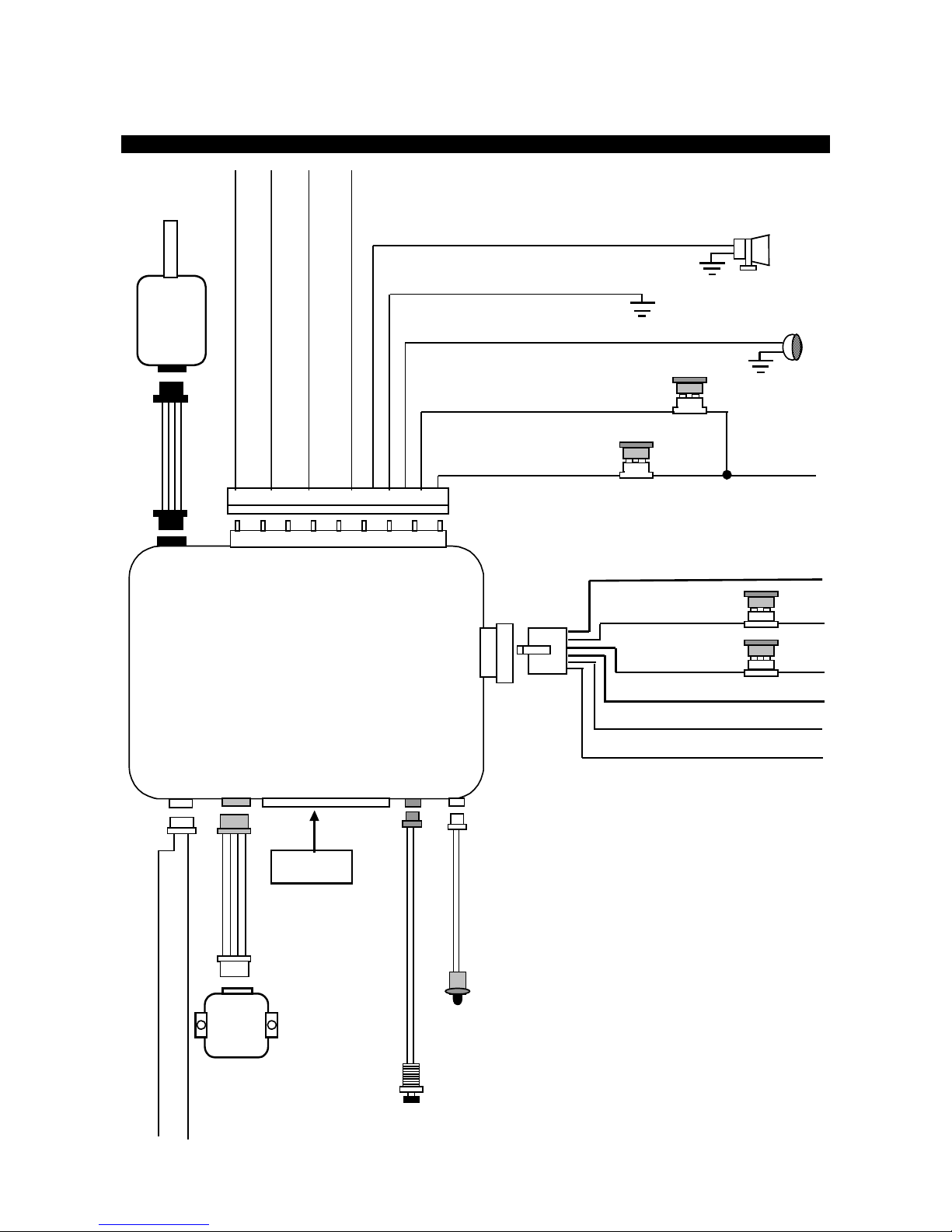
INSTALLATION DIAGRAM
LED
Indicator
VALET
SWITCH
2 Pin
Blue
Two Way
Transceiver
Antenna
2. Red:
+12V Input
3. Red:
+12V Input
4. Yellow:
Ignition 1 output
1. Violet:
Starter Output
20A
Fuse
20A
Fuse
5. Pink:
Ignition 2 Output
Dual
Zone
Shock
Sensor
14 Pin White
Connector
6. Brown:
ACC/Heater Output
ORANGE
:
(
-
)
200
m
A
G
roun
d
O
u
t
pu
t
Wh
en
A
rme
d
Blue: Instant
Trigger
Ground
Input
Green: Negative
Door
Trigger
Input
Violet
: Positive
Door
Trigger
Input
3A Fuse
10A Fuse
3. White:
Parking Light Relay Output
2. Red / White:
Parking Light Power Input
1. Red: +
12V Input
5. Brown:
Positive Output to Siren
4. Black:
Ground to Vehicle Frame
2 Pin
White
14 Pin
White
4 Pin
Orange
3 Pin
White
4 Pin
Black
9 Pin
White
6 Pin
White
-) unlock Pulse , (+) Lock Pu lse
(-) Lock Pulse, (+) Unlock Pulse
VS3725IN
3

FEBERARY/06/2006
14 PIN WHITE MINI CONNECTOR:
1. Wh it e / V iole t
Wire: (
+
) P o s itiv e Sa fe ty Sh u t D ow n I n p u t for Bra k e s witc h .
2. Black/White
Wire: (
-
) N e u tral S a fe ty Sw itc h In p u t &
(
-
) R e mo te S ta r t Tog gle Sw i tc h Inpu t
5. Wh it e / R e d
W ire: T a c h . Signal I n p u t
4. Wh it e / B lac k
Wire: (
-
) N e g ative Sa fe ty Shu t Do wn Input fo r Ho o d pin sw itc h
IMPORTANT NOTE:
Directly connect the BLACK /WH ITE w ire to the “GRO U N D” when this wire is not
used.
3. Wh it e / B lue
W ir e : (
-
) Ins t a n t Sta rt a n d Tu rn Off Inp u t
6. Yellow
Wire: (
-
) 200mA Ignition 3 Control Output
7. Black / Violet
Wire: (
-
)200mA Ch annel 6 Programm able Output
8. Brown / White
W ir e : (
-
) 200mA Programmable Output
1. Horn Output (Factory Default Setting) or
2. Factory Security Rearm Signal Output
9. White
Wire: (
-
) 200mA Dome Light Control Output
10. Black / Red
Wire: (
-
) 200mA Chann el 5 Programm able
11. Black / Green
Wire: (
-
) 200mA Program m able Output
1. Channel 4 Program m ab le Ou tput (Factory Default Setting) or
2.
. G ro u n d Ou tp u t Du ring Sta rt (Cra n k)
12. Gray
Wire: (
-
) 200mA C hannel 3 (Trunk)
13. Pink
W ir e : (
-
) 200mA Programmable Output
1. 2 Steps D oor U nlock Ou tput (Factory Default Setting) or
2. Factory Security Disarm Signal Output or
3.
Start Status (Shock Sensor By-Pass C ontrol) Output
14. Orange / White
Wire: (
-
)200mA G rounded O utput When
WIRING
Keep wiring away from moving engine parts, exhaust pipes and high-tension cable. Tape wires that pass
through holes on the firewall to prevent fraying. Watches out sharp edges that may damage wires and
causes short circuit.
CAUTION: Do not connect the wire harness to the control module until all wiring to vehicle is complete.
6 PIN HEAVY GAUGE WIRING CONNECTIONS:
Remember that the system does to start a vehicle is duplicate the functions of the ignition key switch!
Below, we will explain the three basic functions of the ignition switch. Since this installation will require
analysis of the ignition switch functions, we recommend making the three connections below at the ignition
switch harness directly.
Violet wire – Starter Output –
Careful consideration for the connection of this wire must be made to prevent the vehicle from starting
while in gear. Understanding the difference between a mechanical and an electrical Neutral Start Switch
will allow you to properly identify the circuit and select the correct installation method. In addition you will
realize why the connection of the safety wire is required for all mechanical switch configurations.
Failure to make this connection properly can result in personal injury and property damage.
In all installations it is the responsibility of the installing technician to test the remote start unit and assure
that the vehicle can not start via RF control in any gear selection other than park or neutral.
In both mechanical and electrical neutral start switch configurations; the connection of the VIOLET wire
will be made to the low current start solenoid wire of the ignition switch harness. This wire has +12 volts
when the ignition switch is turned to the “START” (CRANK) position only. This wire have 0 volts in all other
ignition switch positions.
VS3725IN
4
FEBERARY/06/2006
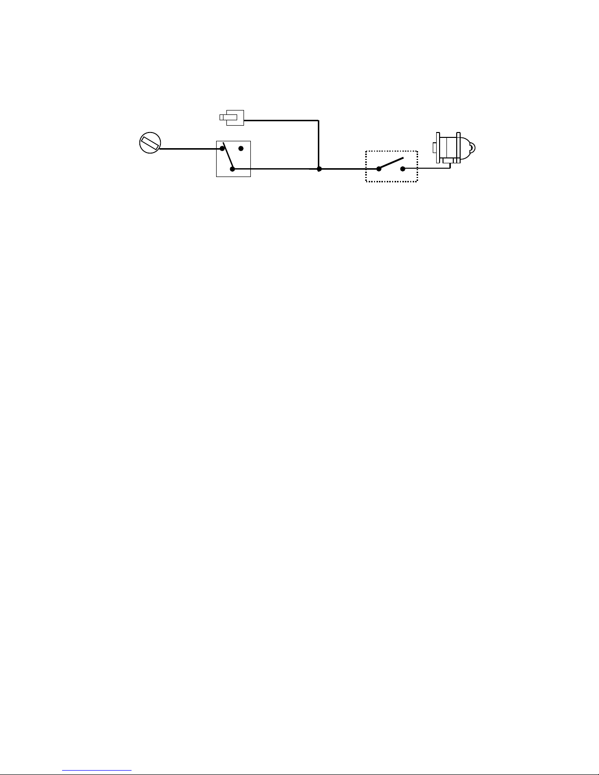
NOTE: This wire must be connected to the vehicle side of the starter cut relay (when used). For the
electrical neutral switch configuration, this connection must be made between the starter inhibit relay
(when used) and the neutral safety switch as shown in the following diagram.
Failure to connect this wire to the ignition switch side of the neutral safety switch can result in personal
injury and property damage. SEE NEUTRAL START SAFETY TEST FOR FURTHER DETAILS.
Start Cut Relay
(When Used)
V
IOLET
Wire
Closed in Park or
Neutral Only
Ignition
Switch
“Start”
“On”
Neutral Safety
Switch
“Acc”
“Off”
Starter
Red wire – +12V Power Input –
Remove the two 20A fuses prior to connecting these wires and do not replace them until the satellite has
been plugged into the control module. These wires are the source of current for all the circuits the relay
satellite will energize. They must be connected to a high current source. Since the factory supplies (+) 12V
to the key switch that is used to operate the motor, it is recommended that these wires be connected
there.
Note: If the factory supplies two separate (+) 12V feeds to the ignition switch, connect one RED wire of the
satellite to each feed at the switch.
Yellow wire – Ignition Output –
Connect the YELLOW wire to the ignition wire from the ignition switch. The ignition wire should receive "12
volts" when the ignition key is in the "ON" or “RUN” and "START" or “CRANK” position. When the ignition
is turned "OFF", the ignition wire should receive "0" voltage. The YELLOW wire must be connected.
Pink wire – Ignition 2 Output
Some vehicles have [2] ignition wires that must be power. Connect the PINK wire to the ignition 2 wire
from the ignition switch. The ignition wire should receive "12 volts" when the ignition key is in the "ON" or
“RUN” and "START" or “CRANK” position. When the ignition is turned "OFF", the ignition wire should
receive "0" voltage. If the PINK wire is not used, cap the end of the wire.
Brown wire – Accessory Output (Heater /ACC Output) –
Connect the BROWN wire to the accessory wire in the vehicle that powers the climate control system.
An accessory wire will show + 12 volts when the ignition switch is turned to the “ACCESSORY” or “ON”
and “RUN” positions, and will show 0 Volts when the key is turned to the “OFF” and “START” or “CRANK”
position. There will often be more than one accessory wire in the ignition harness. The correct accessory
wire will power the vehicle’s climate control system. Some vehicle may have separate wires for the blower
motor and the air conditioning compressor. In such cases, it will be necessary to add a relay to power the
second accessory wire.
9 PIN WIRE HARNESS:
White wire – Parking Light Relay Output (10A power output) –
Connect the WHITE wire to the parking light wire coming from the headlight switch. Do not connect the
WHITE wire to the dashboard lighting dimmer switch. (Damage to the dimmer will result). The limitation of
the WHITE wire is 10 AMP max. Do not exceed this limit or damage to the alarm and parking relay will
result.
Red / White wire – Parking Light Relay Power Input –
The RED/WHITE wire is the input to the flashing parking light relay. The connection of the RED/WHITE
wire will determine the output polarity of the flashing parking light relay.
If the vehicle you are working on has +12volt switched parking light, you don’t need connect this wire. This
wire already connected to +12 volt.
If the vehicle’s parking light are ground switched, cut the RED/WHITE wire, connect the RED/WHITE wire
to chassis ground.
Red wire – System Power (+12V Constant) –
The RED wire supplies power to the system. Connect this wire to a constant +12 volt source.
Brown wire – Siren Drive Output –
This is the positive (+) output connection for the siren. Current capacity is 2 amps. Make connection to
the (+) red wire from the siren. Make the (-) black wire coming from the siren to a good chassis ground.
Black wire – System Ground –
This is main ground connection of the alarm module. Make this connection to a solid section of the vehicle
frame. Do not connect this wire to any existing ground wires supplied by the factory wire loom, make the
connection to the vehicle's frame directly.
Green wire – Negative Door Switch Sensing Input –
VS3725IN
5
 Loading...