

Viking VS 3425 Installation Manual
FEBERARY/06/2006
VS 3425
REMOTE ENGINE STARTER WITH
ALARM SYSTEM
Installation Manual
MEGATRONIX
VAN NUYS, CA U.S.A.
560A
1

FEBERARY/06/2006
INTRODUCTION
INSTALLER WARNINGS
This Remote Starter with Alarm System is designed to be installed on fuel injected vehicles with an
automatic transmission ONLY.
Never install this remote starter on a manual transmission vehicle.
This system must be installed and wired through a safety switch it will not start in any forward or reverse
gear.
Some automatic transmission vehicle [mainly older GM vehicles with a purple starter wire] have a
mechanical-type park safety switch instead of electrical safety switch. The mechanical type does not
interrupt the starter circuit when the transmission is any gear and does not offer the 100% level of safety
required for remote starting purposes. Therefore, our system should never be installed on any vehicle that
uses a mechanical type park safety switch.
Once you install this system, you must verify that the vehicle will not start any forward or reverse gear.
Regardless of the type of vehicle.
Read operation manual for operating and programming routine.
Do not install any component near the brake, gas pedal or steering linkage.
Some vehicles have a factory installed transponder immobilizer system that can severely complicate the
installation. There is possibility that this system can not be installed on some immobilizer equipped
vehicles.
Most vehicles have an SRS air bag system. Use extreme care and do not probe any wires of the SRS
system.
Disconnect the car battery before connecting work on the vehicle.
Check behind panels before drilling any holes. Ensure that no wiring harness or other components are
located behind the panels that would otherwise be damaged.
Use conventional crimp lock, bullet on any wiring. Poor wiring, i.e. taped joints will possibly introduce
unreliability into the alarm system and may result in false alarms or incorrect operation.
Install wiring neatly under carpets or behind trim to prevent possible damage to wires.
For the wire operates the current more than 10A. We suggest soldering all connection point. Do not use
crimp lock type connectors or wire nuts.
560A
2
FEBERARY/06/2006
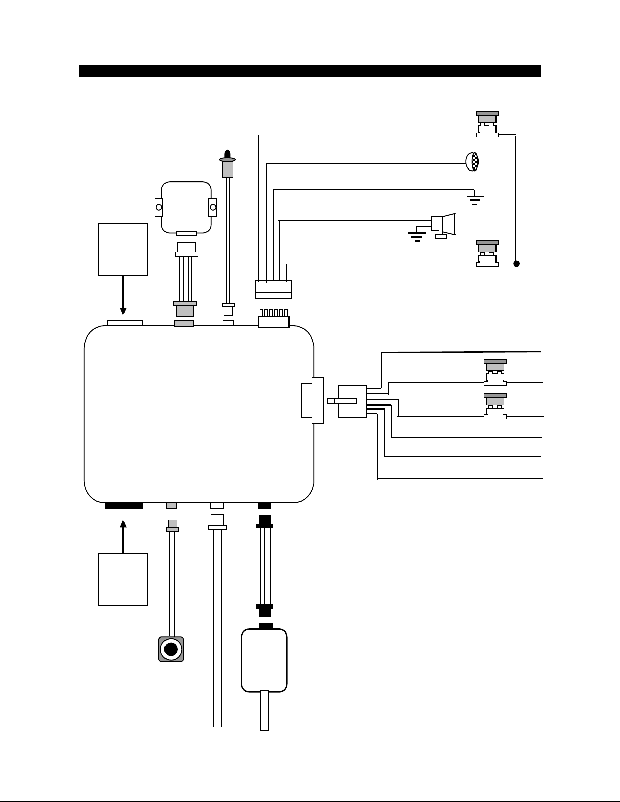
INSTALLATION DIAGRAM
H 8
3 Pin
White
H 1
6 Pin
White
H 2
5 Pin
White
H 3
2 Pin
White
H 4
4 Pin
Orange
H 5
5 Pin
White
VALET
SWITCH
H 6
7 Pin
Blac k
H 7
2 Pin
Blue
Dual Zone
Shock
Sensor
H 9
3 Pin
Black
5. Pink:
Ignition 2 output
2. Red:
+12V Input
3. Red:
+12V Input
4. Yellow:
Ignition 1 output
1. Violet:
Starter Output
20A
Fuse
20A
Fuse
6. Brown:
ACC/Heater Output
LED
Indicator
1. Red/White:
Parking Light Relay Power input
2. White:
Parking Light Relay Output
3. Black:
Ground to Vehicle Frame
4. Brown:
Positive Output to Siren
5. Red:
+12V Input
3A Fuse
10A Fuse
H5
5 Pin White
Connector
for Output
Connection
H6
7 Pin Black
Connector
for Input
Connection
3. Green: (-) Lock Pulse. Or (+)Unlock Pul
s
1. Blue:
(
-
) Unlock Pulse. Or (
+
)Lock Pulse
Windshield
Receiver
Antenna
560A
3
FEBERARY/06/2006
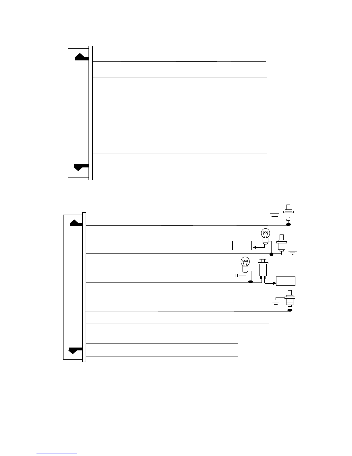
#H5 5 PIN WHITE CONNECTOR FOR OUTPUT CONNECTION
3. White
Wire: (-) 200 mA Programmable output
Dome Light Control Output (Factory Default setting)
Or Horn Output
Or Factory Security Rearm Signal Output
Or Ground Output During Start (Crank)
1. Orange
Wire: (-) 500mA Grounded Output When Armed
5. Gray
Wire: (-) 200 mA Channel 3 (Trunk) Output
2. Yellow
Wire: (-) 200 mA Ignition 3 Control Output
4. Pink
Wire: (-) 200 mA Programmable output
2-Step Door Unlock Output (Factory Default setting)
Or Factory Security Disarm Signal Output
Or Start Status (Shock Sensor Bypass Control) Output
#H6. 7 PIN BLACK CONNECTOR FOR INPUT CONNECTION:
2. Green
Wire:
Zone 3
Negative Door Pin Trigger Input:
1. Blue
Wire:
Zone 2
Instant Trigger Ground Input
3. Violet
Wire:
Zone 3
Positive Door Pin Trigger
5. White/Violet
Wire: (
+
) Positive Safety Shut Down Input for Brake switch.
6. Black/White
Wire: (
-
) Neutral Safety Switch Input &
(
-
) Remote Start Toggle Switch Input
7. White/Red
Wire: Tach. Signal Input
+12V
4. White/Black
Wire: (
-
) Negative Safety Shut Down Input for Hood pin switch
IMPORTANT NOTE:
Directly connect the H6/6 BLACK/WHITE wire to the “GROUND” when this wire
is not used.
+12V
560A
4
FEBERARY/06/2006
WIRING
Keep wiring away from moving engine parts, exhaust pipes and high-tension cable. Tape wires that pass
through holes on the firewall to prevent fraying. Watches out sharp edges that may damage wires and
causes short circuit.
CAUTION: Do not connect the wire harness to the control module until all wiring to vehicle is complete.
H1: 6 PIN HEAVY GAUGE WIRING CONNECTION:
Remember that the system does to start a vehicle is duplicate the functions of the ignition key switch!
Below, we will explain the three basic functions of the ignition switch. Since this installation will require
analysis of the ignition switch functions, we recommend making the three connections below at the ignition
switch harness directly.
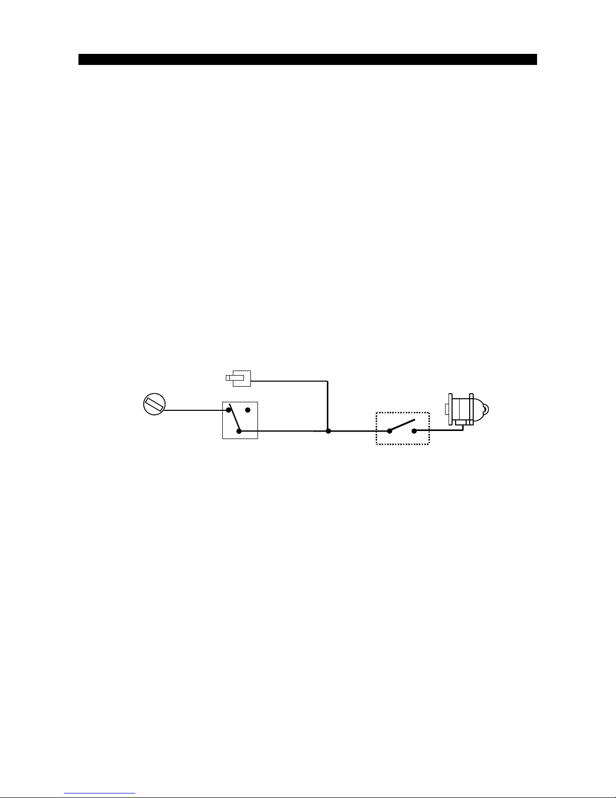
H1/1. Violet Wire—Starter Output
Careful consideration for the connection of this wire must be made to prevent the vehicle from starting
while in gear. Understanding the difference between a mechanical and an electrical Neutral Start Switch
will allow you to properly identify the circuit and select the correct installation method. In addition you will
realize why the connection of the safety wire is required for all mechanical switch configurations.
Failure to make this connection properly can result in personal injury and property damage.
In all installations it is the responsibility of the installing technician to test the remote start unit and assure
that the vehicle can not start via RF control in any gear selection other than park or neutral.
In both mechanical and electrical neutral start switch configurations, the connection of the VIOLET wire
will be made to the low current start solenoid wire of the ignition switch harness. This wire have +12 volts
when the ignition switch is turned to the “START” (CRANK) position only. This wire have 0 volts in all other
ignition switch positions.
NOTE: This wire must be connected to the vehicle side of the starter cut relay (when used). For the
electrical neutral switch configuration, this connection must be made between the starter inhibit relay
(when used) and the neutral safety switch as shown in the following diagram.
Failure to connect this wire to the ignition switch side of the neutral safety switch can result in personal
injury and property damage. SEE NEUTRAL START SAFETY TEST FOR FURTHER DETAILS.
Start Cut Relay
(When Used)
V
IOLET
Wire
Closed in Park or
Neutral Only
Ignition
Switch
“Start”
“On”
Neutral Safety
Switch
“Acc”
“Off”
Starter
H1/2 & H1/3. Red Wire (2)-- +12V Power Input
Remove the two 20A fuses prior to connecting these wires and do not replace them until the satellite has
been plugged into the control module. These wires are the source of current for all the circuits the relay
satellite will energize. They must be connected to a high current source. Since the factory supplies (+) 12V
to the key switch that is used to operate the motor, it is recommended that these wires be connected
there.
Note: If the factory supplies two separate (+) 12V feeds to the ignition switch, connect one RED wire of the
satellite to each feed at the switch.
H1/4. Yellow Wire – Ignition 1 Output
Connect the YELLOW wire to the ignition 1 wire from the ignition switch. The ignition wire should receive
"12 volts" when the ignition key is in the "ON" or “RUN” and "START" or “CRANK” position. When the
ignition is turned "OFF", the ignition wire should receive "0" voltage.. The YELLOW wire must be
connected.
H1/5. PINK Wire – Ignition 2 Output
Some vehicles have [2] ignition wires that must be power. Connect the PINK wire to the ignition 2 wire
from the ignition switch. The ignition wire should receive "12 volts" when the ignition key is in the "ON" or
“RUN” and "START" or “CRANK” position. When the ignition is turned "OFF", the ignition wire should
receive "0" voltage. If the PINK wire is not used, cap the end of the wire.
H1/6. Brown Wire –Accessory Output (Heater /AC Output)
Connect the BROWN wire to the accessory wire in the vehicle that powers the climate control system.
An accessory wire will show + 12 volts when the ignition switch is turned to the “ACCESSORY” or “ON”
and “RUN” positions, and will show 0 Volts when the key is turned to the “OFF” and “START” or “CRANK”
position. There will often be more than one accessory wire in the ignition harness. The correct accessory
wire will power the vehicle’s climate control system. Some vehicle may have separate wires for the blower
560A
5
FEBERARY/06/2006
motor and the air conditioning compressor. In such cases, it will be necessary to add a relay to power the
second accessory wire.
H2: 5 PIN WIRE HARNESS:
H2/1. RED / WHITE WIRE –PARKING LIGHT RELAY INPUT --
The RED/WHITE wire is the input to the flashing parking light relay. The connection of the RED/WHITE
wire will determine the output polarity of the flashing parking light relay.
If the vehicle you are working on has +12volt switched parking lights, you don’t need connect this wire.
This wire already connected to +12volt.
If the vehicle’s parking lights are ground switched, cut the RED/WHITE wire, connect the RED/WHITE
wire to chassis ground.
H2/2. WHITE WIRE -- PARKING LIGHT RELAY OUTPUT (+12 V 10A OUTPUT) --
Connect the WHITE wire to the parking light wire coming from the headlight switch. Do not connect the
WHITE wire to the dashboard lighting dimmer switch. (Damage to the dimmer will result). The limitation of
the WHITE wire is 10 AMP max. Do not exceed this limit or damage to the alarm and parking relay will
result.
H2/3. BLACK WIRE -- SYSTEM GROUND –
This is main ground connection of the alarm module. Make this connection to a solid section of the vehicle
frame. Do not connect this wire to any existing ground wires supplied by the factory wire loom, make the
connection to the vehicle's frame directly.
H2/4. BROWN WIRE – PROGRAMMABLE OUTPUT
This is the positive (+) output connection for the siren. Current capacity is 2 amps. Make connection to the
(+) red wire from the siren. Make the (-) black wire coming from the siren to a good chassis ground.
H2/5. RED WIRE -- SYSTEM POWER (+12V CONSTANT) --
The RED wire supplies power to the system. Connect this wire to a constant +12 volt source.
H3. 2 PIN WHITE CONNECTOR FOR THE LED STATUS INDICATOR:
The led indicator status should be mounted in a highly visible area such as top of the dashboard, on top of
the shifter console or on dashboard face. Leave at least 6mm space behind the mounting location for LED
housing. Once a suitable location is chosen, drill a 6mm hole. Run the LED wires through the hole then
press the 2 pin LED housing into the place. Route the LED wires to the control module.
H4. 4 PIN ORANGE CONNECTOR FOR 2 STAGE SHOCK SENSOR
4. Green
Wire /
Zon e 1
Warn Away Input
3. Blue
Wire /
Zone 4
Ground Trigger
2. Black
Wire / Negative
1. Red
Wire / +12Volts
H5: 5-PIN MINI WHITE CONNECTOR WIRE HARNESS:
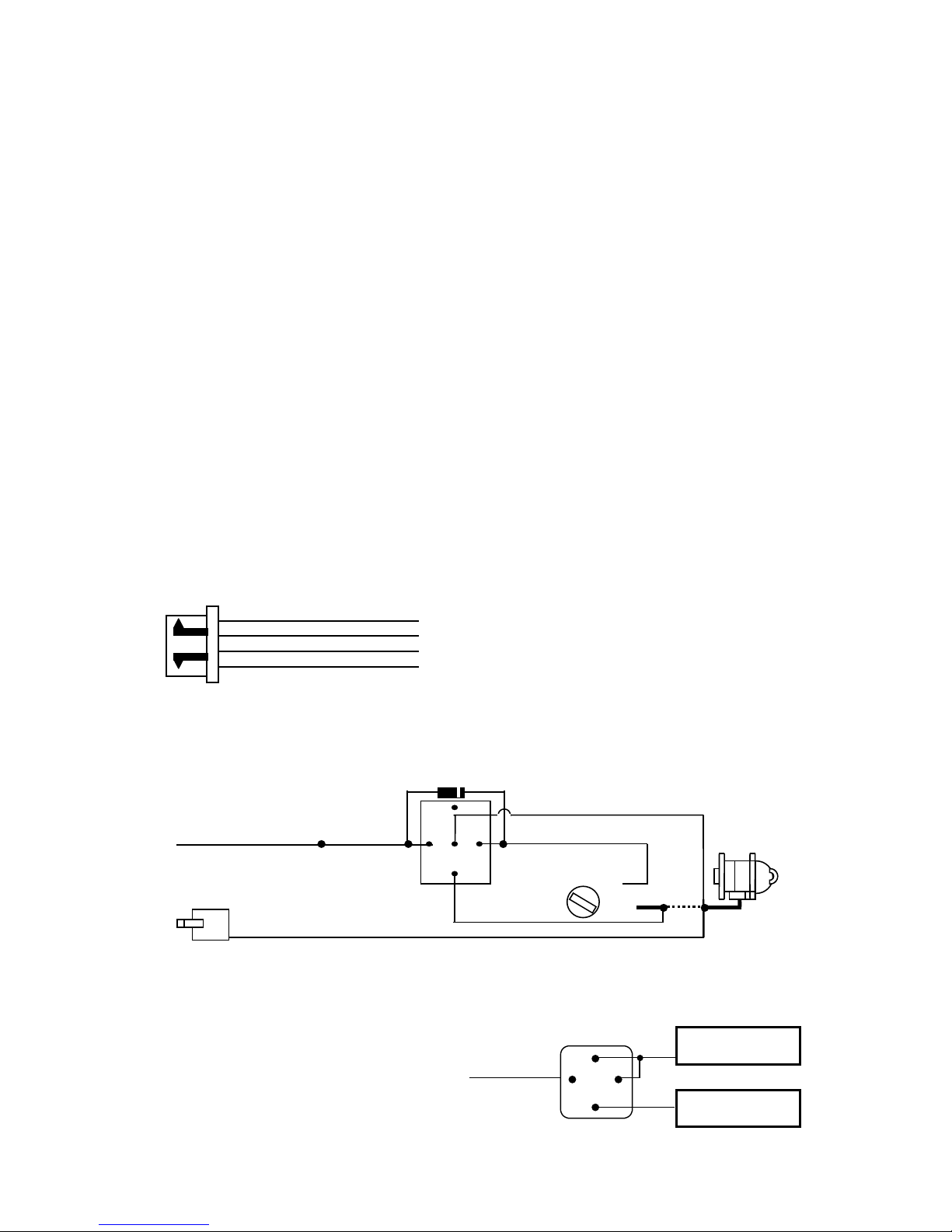
H5/1 ORANGE WIRE – (-) 500ma GROUNDED OUTPUT WHEN ARMED --
This wire will become grounded when the alarm is armed. The current capacity of this wire is 200mA. This
output can control starter disable, when an intrusion is detected and the system is triggered. The vehicles
prevent from any unauthorized starting.
87
87a
85
30
86
IN4003 Diode
H5/1
: ORANGE wire
from control module
“Start”
“On”
White wire
X
Cut
Red wire
Orange wire
“Acc”
“Off”
Starter
H1/1
VIOLET wire (Starter output)
form Heavy Gauge wire harness
Yellow wire to
Ignition Switch
H5/2. YELLOW WIRE:- (-) 200ma IGNITION 3 OUTPUT–
This wire provides a 200mA (-) ground output that becomes active 4 seconds before the remote start unit
initialize, and remains grounded while running.
Ignition 3 output:
Some newer vehicles use a third ignition wire
which is required to start and keep the vehicle’s
engine running. If this is the case, wire an IGN 3
relay (not supplied) as shown below:
Do not connect any vehicle circuits together, they
are isolated for a resaon.
Yellow Wire
87a
Ignition 3 Wire From
Ignition Key Switch
+ 12 V Constant
Fused 25A Capable
30
8586
87
Transponder interfacing using relay:
560A
6
 Loading...