

Page 1

Installation
GUIDE
5 SERIES
Built-in Gas Rangetops
VRT530 / CVRT530
VRT536 / CVRT536
VRT548 / CVRT548
Page 2
Table of Contents
Warnings & Important Safety Information ________________________________________________________________ 3
Dimensions ________________________________________________________________________________________ 4
Speci cations _______________________________________________________________________________________ 5
Clearance Dimensions ________________________________________________________________________________ 6
Electrical & Gas Requirements _________________________________________________________________________ 8
General Information __________________________________________________________________________________ 9
Installation _________________________________________________________________________________________ 9
Final Preparation ___________________________________________________________________________________ 10
Performance Checklist _______________________________________________________________________________ 10
Service & Registration _______________________________________________________________________________ 11
Important Safety Instructions– Read and Follow!
Before beginning, please read these instructions completely and carefully.
Your safety and the safety of others is very important.
We have provided many important safety messages in this manual and on your appliance. Always read and obey all safety
messages.
This is the safety alert symbol. This symbol alerts you to hazards that can kill or hurt you and others.
All safety messages will be preceded by the safety alert symbol and the word “DANGER,” “WARNING” or “CAUTION.” These words
mean:
DANGER
Hazards or unsafe practices which WILL
result in severe personal injury or death
WARNING
Hazards or unsafe practices which COULD
result in severe personal injury or death.
CAUTION
Hazards or unsafe practices which COULD result
in minor personal injury or property damage.
All safety messages will identify the hazard, tell
you how to reduce the chance of injury, and tell
you what can happen if the instructions are not
followed.
IF THE INFORMATION IN THIS MANUAL IS NOT
FOLLOWED EXACTLY, A FIRE OR EXPLOSION MAY
RESULT CAUSING PROPERTY DAMAGE, PERSONAL
INJURY, OR DEATH.
• Do not store or use gasoline or other ammable vapors and
liquids in the vicinity of this or any other appliance.
• WHAT TO DO IF YOU SMELL GAS:
–Do not try to light any appliance.
–Do not touch any electrical switch;
DO NOT use any phone in your building.
– Immediately call your gas supplier from a neighbor’s phone.
–Follow the gas supplier’s instructions.
–If you cannot reach your gas supplier, call the re department.
• Installation and service must be performed by a quali ed
installer, service agency, or the gas supplier.
DANGER
FIRE/EXPLOSION HAZARD
2
Page 3
Important - Please Read and Follow
• Before beginning, please read these instructions completely and carefully.
• Do not remove permanently a xed labels, warnings, or plates from product. This may void the warranty.
• All local and national codes and ordinances must be observed. Installation must conform with local codes or in the absence of
codes, the National Fuel Gas Code ANSIZ223.1/NFPA-54 –latest edition.
•The installer must leave these instructions with the consumer who should retain for local inspector’s use and for future reference.
In Canada: Installation must be in accordance with the current CSA C22.1 Canadian Electrical Codes Part 1 and/or local codes.
Installation must be in accordance with the current CAN/CGA B149.1 & 2 Gas Installation codes and/or local codes. Electrical
installation must be in accordance with the current CSA C22.1 Canadian Electrical Codes Part 1 and/or local codes.
In Massachusetts: All gas products must be installed by a “Massachusetts” licensed plumber or gas tter. A “T” type handle manual
valve must be installed in the gas supply line to the appliance.
An air curtain or other overhead range hood which operates by blowing a downward air ow onto the range, shall not be used
with a gas range.
A GFI shall be used if required by NFPA-70 (National Electric Code), federal/state/local laws, or local ordinances.
• The required use of a GFI is normally related to the location of a receptacle with respect to any signi cant sources of water or
moisture.
• Viking Range, LLC will NOT warranty any problems resulting from GFI outlets which are not installed properly or do not meet the
requirements below.
If the use of a GFI is required, it should be:
•Of the receptacle type (breaker type or portable type NOT recommended)
•Used with permanent wiring only (temporary or portable wiring NOT recommended)
•On a dedicated circuit (no other receptacles, switches or loads in the circuit)
•Connected to a standard breaker of appropriate size (GFI breaker of the same size NOT recommended)
•Rated for Class A (5 mA +/- 1 mA trip current) as per UL 943 standard
•In good condition and free from any loose- tting gaskets (if applicable in outdoor situations)
•Protected from moisture (water, steam, high humidity) as much as reasonably possible
WARNING DANGER
To prevent possible damage to cabinets and cabinet
nishes, use only materials and nishes that will not
discolor or delaminate and will withstand temperatures
up to 194°F (90°C). Heat resistant adhesive must be used
if the product is to be installed in laminated cabinetry.
Check with your builder or cabinet supplier to make sure
that the materials meet these requirements.
WARNING
This appliance shall not be used for space heating. This
information is based on safety considerations.
To avoid risk of property damage and/or
personal injury or death; this appliance is not
too be used as a heating source.
• Benzene is a chemical which is part of the gas supply to
this cooking product, which is consumed in the ames
during combustion. Exposure to a small amount of
benzene is possible if a gas leak occurs. Formaldehyde
and soot are by-products of incomplete combustion.
• This appliance contains or produces chemicals which
can cause serious injury or death and which are known
to the state of California to cause cancer, birth defects
or other reproductive harm. To reduce the risk from
substances in the fuel or from fuel combustion make
sure this appliance is installed, operated, and maintained
in accordance to the instructions in this document.
CHEMICAL HAZARD
3
Page 4
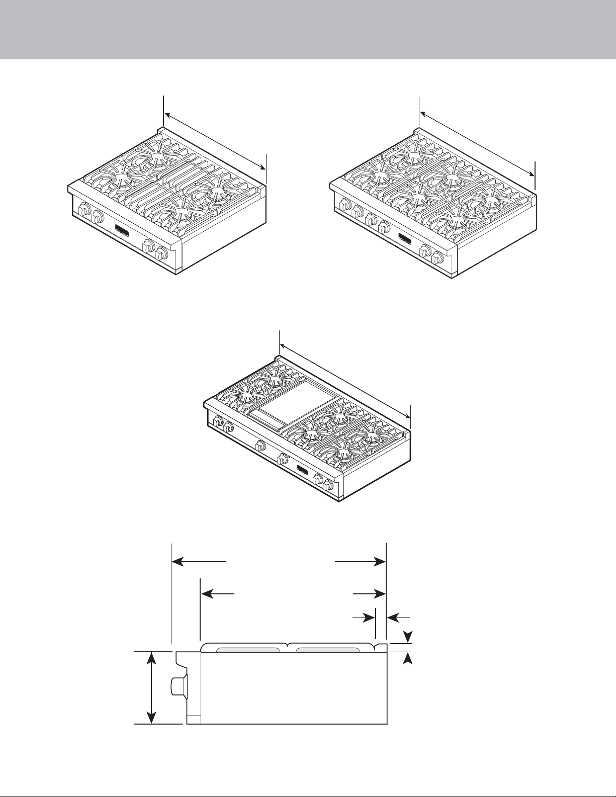
Dimensions
30” W. Gas Rangetop
29-7/8”
(75.9 cm)
36” W. Gas Rangetop
48” W. Gas Rangetop
47-7/8”
(121.6 cm)
35-7/8”
(91.1 cm)
Side View
8-1/8”
(20.6 cm)
28-9/16” (72.6 cm)
24-5/16” (61.8 cm)
1-5/8” (4.1 cm)
1” (2.5 cm)
Note: Unit shown with standard island trim
4
Page 5

Speci cations
VRT5 Series Gas Rangetops
Description 30” W. Models 36” W. Models 48” W. Models
Overall width 29-7/8” (75.9 cm) 35-7/8” (91.1 cm) 47-7/8” (121.6 cm)
Overall height
(from bottom)
Additions to base
height
Overall depth
(from rear)
Cutout dimensions
Width
Height
Depth
Gas requirements Shipped natural or LP/Propane gas; eld convertible with conversion kit (purchased separately);
Gas manifold pressure Natural 5.0” W.C.P. / Liquid propane L/P 10.0” W.C.P.
Electrical requirements 120 VAC/60 Hz 4ft. (121.9 cm), 3-wire cord with grounded 3-prong plug
Max. amp usage 0.5 amp
Surface burner rating
Natural/LP
Griddle burner rating N/A 15,000 BTU Nat./12,500 BTU LP/Propane
Approximate shipping
weight
30” (76.2 cm)
7-5/8” (19.4 cm)
min. 24” (61.0 cm)/
max. 25-3/4” (65.4 cm)
accepts standard residential 1/2” (1.3 cm) ID gas service line.
(1) 18,500 BTU (5.4 kW)/16,600 BTU (4.9kW) power burner
125 lbs.
(56.7 kg)
To top of grate—9-1/4” (23.5 cm)
To top of island trim—9-1/8” (23.2 cm)
To top of backguard—add 8” (20.3 cm)
To top of high shelf—add 23-1/2” (59.7 cm)
To end of side panel—24-5/16” (61.8 cm)
To end of landing edge—28-1/16” (71.3 cm)
To end of knobs—28-9/16” (72.6 cm)
36” (91.4 cm)
7-5/8” (19.4 cm)
min. 24” (61.0 cm)/
max. 25-3/4” (65.4 cm)
15,000 BTU (4.4 kW)/12,500 BTU (3.7 kW)
(4.4 kW Nat/ 3.7 kW LP)
6B-150 lbs. (67.5 kg)
4G-160 lbs. (72.0 kg)
48” (121.9 cm)
7-5/8” (19.4 cm)
min. 24” (61.0 cm)/
max. 25-3/4” (65.4 cm)
6G-203 lbs. (91.4 kg)
8B-200 lbs. (90.7 kg.)
Minimum clearances from adjacent combustible construction
• Cooking surface and below, i.e., 36” (91.4 cm) and below
o Sides—0”
• Above cooking surface, i.e. above 36" (91.4 cm)
o Sides—6” (15.2 cm)
o Within 6” (15.2 cm) side clearance, wall cabinets no deeper than 13” (33.0 cm) must be minimum 18” (45.7 cm)
above cooking surface.
o Wall cabinets directly above product must be a minimum of 42” (106.7 cm) above cooking surface, unless a
range hood is installed above the cooking surface.
o Rear—0” with backguard or highshelf; 0” with island trim and noncombustible rear wall; 6” (15.2 cm) with island
trim and combustible rear wall.
5
Page 6

Clearance Dimensions
•This rangetop may be installed directly adjacent to existing 36” (91.4 cm) high base cabinets.
IMPORTANT: The top of the side trim MUST be 3/8” (.95 cm) above the adjacent base cabinet countertop.
• The rangetop CANNOT be installed directly adjacent to sidewalls, tall cabinets, tall appliances, or other side vertical surfaces
above 36” (91.4 cm) high. There must be a minimum of 6” (15.2 cm) side clearance from the rangetop to such combustible
surfaces above the 36” (91.4 cm) counter height.
• Within the 6” (15.2 cm) side clearance to combustible vertical surfaces above 36” (91.4 cm), the maximum wall cabinet depth
must be 13” (33.0 cm) and wall cabinets within this 6” (15.2 cm) side clearance must be 18” (45.7 cm) above the 36” (91.4 cm) high
countertop.
• Wall cabinets above the rangetop must be a minimum of 42” (106.7 cm) above the rangetop cooking surface for the full width of
the rangetop. This minimum height requirement does not apply if a rangetop hood is installed over the cooking surface.
CAUTION
BURN HAZARD
To avoid risk of personal injury; the
use of cabinets for storage above the
appliance may result in a potential
burn hazard. Combustible items may
13” max.
33.0 cm)
(
6” min.
(15.2 cm)
42” min.
(106.7 cm)
ignite, metallic items may become hot and cause
burns. If a cabinet storage is to be provided the
risk can be reduced by installing a rangehood
that projects horizontally a minimum 5” (12.7 cm)
beyond the bottom of cabinets.
25-3/4”
(65.4 cm)
8-1/8”
(20.6 cm)
(0.95 cm)
Note: Based on 24” (61 cm) deep cabinet.
Note: Minimum clearance for back wall is 0” with
backguard or high-shelf.
Note: If a rangetop hood is installed, wall cabinets above
the rangetop have a di erent minimum clearance height.
3/8”
min.
18”
(45.7 cm
6
)
Page 7

Clearance dimensions
The bottom of a standard hood should be 30” (76.2 cm)
min. to 36” (91.4 cm) max. above the countertop. This would
typically result in the bottom of the hood being 66” (167.6
cm) to 72” (182.9 cm) above the oor. Refer to the rangetop
hood installation instructions for additional information. These
dimensions provide for safe and e cient operation of the hood.
Wood/Composite
Overlay
Note: Minimum clearance for back wall is
0” with backguard or high-shelf.
Wood/Composite
Overlay
66”min.
(167.6 cm)
to
72”max.
(182.9 cm)
30”
(76.2 cm)
6”
(15.2 cm)
30”min.
(76.2 cm)
to
36”max.
(91.4 cm)
66”min.
(167.6 cm)
to
72”max.
(182.9 cm)
Wall Installation
24”
(61.0 cm)
or
27”
(38.6 cm)
0”
0 cm)
(
30”min.
(76.2 cm)
to
36”max.
(91.4 cm)
Island Installation
Important: This rangetop comes
standard with an Island Trim. There
must be a minimum of 6” (15.2 cm)
clearance from rear of rangetop to a
combustible wall. Clearances from
non-combustible materials are not
part of the ANSI Z21.1 scope and
are not certi ed by CSA. Clearances
to non-combustible materials
must be approved by the authority
having jurisdiction.
Note: -6” (15.2 cm) min. with island trim and
combustible rear wall.
-0” with island trim and non-ombustible
rear wall.
7
Page 8

Electrical & Gas Requirements
Electrical Requirements
There is no connection necessary beyond plugging the unit
into a polarized, grounded, 120 volt, 60 Hz, 15 amp circuit. The
minimum of 120 VAC is required for proper operation of gas
ignition systems. This circuit MUST be grounded and properly
polarized. The unit is equipped with a 16-SPT2 power cord.
Gas Connection
The gas supply (service) line must be the same size or greater than
the inlet line of the appliance. This rangetop uses a 1/2” (1.3 cm) ID
NPT (Sch40) inlet. Sealant on all pipe joints must be resistive to LP
gas.
The rangetop is designed speci cally for natural gas or liquid
propane (LP) gas. Before beginning installation, verify that the model
is compatible with the intended
gas supply.
Manual shut-o valve:
This installer-supplied valve must be installed in the gas service line before the appliance in the gas stream and in a location where
it can be reached quickly in the event of an emergency. Any opening behind the rangetop should be sealed.
In Massachusetts: A “T” handle type manual valve must be installed in the gas supply line to the appliance.
To avoid risk of personal injury or death;
• DO NOT USE AN OPEN FLAME TO CHECK FOR GAS LEAKS.
To avoid the risk of electrical shock, personal
injury or death; verify electrical power is
turned o at the breaker box and gas supply is
turned o until the rangetop is installed and ready to
operate, installation by an authorized installer only.
WARNING
Electrical shock hazard
DANGER
GAS LEAK HAZARD
leak testing of the appliance must be
conducted according to the manufacturer’s
instructions. Before placing appliance in
operation, always check for gas leaks with
soapy water solution.
IMPORTANT: Any conversion required must be performed by your dealer or a quali ed licensed plumber or gas service company.
Please provide the service person with this manual before work begins.
Pressure Regulator:
• All heavy-duty, commercial type cooking equipment must have a pressure regulator on the incoming service line for safe and
e cient operation, since service pressure may uctuate with local demand. External regulators are not required on this rangetop
since a regulator is built into each unit at the factory. Under no condition bypass this built-in regulator.
• Manifold pressure should be checked with a manometer, natural
gas requires 5.0” W.C.P. and LP gas requires 10.0” W.C.P. Incoming line
pressure upstream from the regulator must be 1” W.C.P. higher than
the manifold pressure in order to check the regulator. The regulator
used on this range can withstand a maximum input pressure of 1/2”
PSI (14.0” W.C.P.). If the line pressure is in excess of that amount, a step
down regulator will be required.
• The appliance must be disconnected from the gas supply piping
system during any pressure testing of that system.
24” max.
61.0 cm)
(
to
25” max.
65.4 cm)
(
3”
(7.6 cm)
1-1/2”
(3.8 cm)
Flexible Connections:
If the unit is to be installed with exible couplings and/or quickdisconnect ttings, the installer must use a heavy-duty AGA
design-certi ed exible connector of at least 1/2” (1.3 cm) ID
NPT (with suitable strain reliefs) in compliance with ANSI Z21.41
and Z21.69. In Canada: CAN 1-6, 10-88 metal connectors for gas
appliances and CAN 1-6.9 M79 quick disconnect devices for use
with gas fuel.
In Massachusetts: This appliance must be installed with a 36” (3foot) long exible gas connector.
8
Page 9

General Information
READ AND FOLLOW ALL WARNING AND CAUTION INFORMATION WHEN
INSTALLING THIS APPLIANCE.
WARNING
• All openings in the wall behind the appliance and in the oor under the
appliance should be sealed.
• Do not obstruct the ow of combustion and ventilation air.
Moving, Handling, and Unpacking
• Remove and discard all packing materials, including cardboard and tape
on the outside of the rangetop.
• Remove the burner grates and styrofoam o the top cooking surface.
Be sure to remove the burner caps packaged in styrofoam below the
burner grates.
• Some stainless steel parts may have a plastic protective wrap which
must be peeled o . The interior should be washed thoroughly with hot,
soapy water to remove lm residues and any dust or debris before being
used, then rinsed and wiped dry. Solutions stronger than soap and
water are rarely needed.
Installation
Note: Refer to rangetop electrical
& gas requirements section for
proper installation information.
Moving hazard
To avoid risk of severe personal injury;
this appliance requires two or more
personnel while handling and moving.
Possible use of appliance moving
devices is recommended.
1
Connect gas and electrical in shaded area.
See the “Electrical & Gas Requirements” section
for more information.
2
Slide rangetop into place.
9
Page 10

Final Preparation
Some stainless steel parts may have a protective wrap, which must be peeled o .
All stainless steel body parts should be wiped regularly with hot, soapy water at the end of each cooling period and with liquid
cleaner designed for this material when soapy water will not do the job.
If build-up occurs, DO NOT use steel wool, or abrasive cloths, cleaners, or powders. If it is necessary to scrape stainless steel
surface to remove encrusted material, soak area with hot, wet towels to loosen the material, then use a wooden or nylon spatula
or scraper. DO NOT use a metal knife, spatula, or any other metal tool to scrape stainless steel surfaces. Scratches are almost
impossible to remove. DO NOT permit citrus or tomato juice to remain on stainless steel surface, as citric acid will permanently
discolor stainless steel. Wipe up any spills immediately.
Performance Checklist
quali ed installer should check top burner ignition.
See drawing for proper ame height on HI. The low ame should light at
every port.
1-1/2”
(3.8 cm)
3/8”
(0.95 cm)
10
Page 11

Service & Registration
If service is required, call your authorized service agency.
Have the following information readily available.
• Model number
• Serial number
• Date purchased
• Name of dealer from whom purchased
Clearly describe the problem that you are having. If you are unable to obtain the name of an authorized service agency, or if you
continue to have service problems, contact Viking Range, LLC at 1-888-845-4641, or write to:
VIKING RANGE, LLC
PREFERRED SERVICE
111 Front Street
Greenwood, Mississippi 38930 USA
Record the information indicated below. You will need it if service is ever required. The model and serial
number for your rangetop can be found by lifting up the front of the unit and looking underneath on the base.
Model no. _________________________________________Serial no. ___________________________________
Date of purchase ___________________________________Date installed _______________________________
Dealer’s name _________________________________________________________________________________
Address ______________________________________________________________________________________
_____________________________________________________________________________________________
If service requires installation of parts, use only authorized parts to insure protection under the warranty.
Keep this manual for future reference.
11
Page 12

Viking Range, LLC
111 Front Street
Greenwood, Mississippi 38930 USA
(662) 455-1200
For product information, call 1-888-845-4641
or visit our website at vikingrange.com in the US
or brigade.ca in Canada
064096-000 EN (080117)
 Loading...