

Viking VDR7364GBK, VGRT7364GSS, RVGR33025BSSLP, VDSC5304BBK, VRT5366BSS Installation
...
Viking Installation Guide
Viking Range Corporation
111 Front Street
Greenwood, Mississippi 38930 USA
(662) 455-1200
For product information
call 1-888-VIKING1 (845-4641)
or visit the Viking Web site at
vikingrange.com
F1448K EN
Range/Rangetop Rear Trim Accessories
& Range Curb Base Fronts
(020211)
A
X
A
BB
B
A
B
Rear Trim Accessories
Rear Trim Accessories
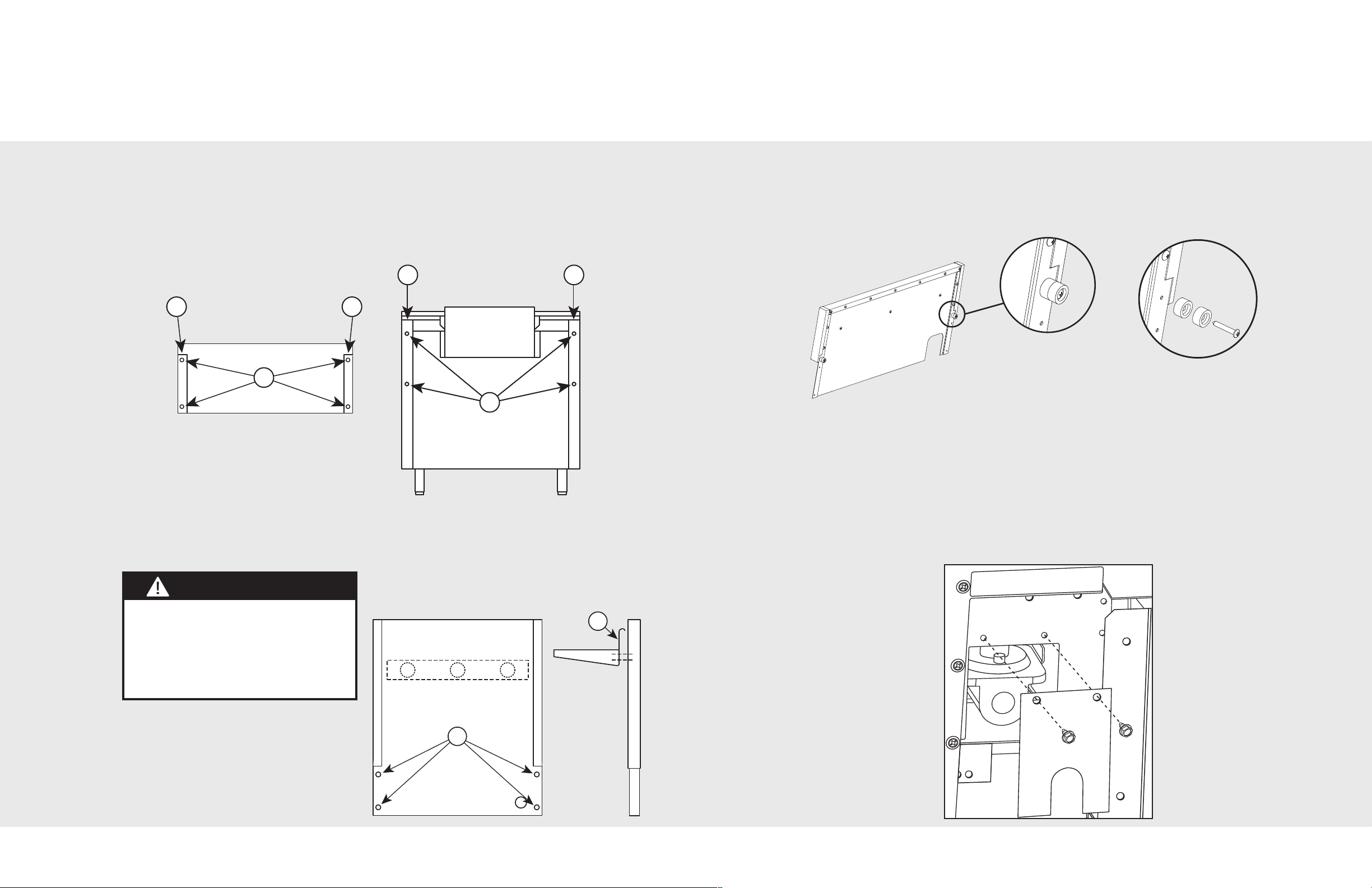
All rear trim devices are installed in the same basic way.
ATTACHING REAR TRIM (Illustration I)
Grasp the trim on each end and carefully place in the channels (B) located at each rear corner of the
product. Align the screw holes (A) at each end of the trim device with the holes (A) in each rear channel
of the product. Secure with the 4 enclosed screws.
(Illustration I)
RANGE REAR
VIEW
RANGETOP
REAR VIEW
ATTACHING BACKGUARD (Illustration III)
Backguards come equipped with Nylon Spacers (See Figure 1), which are needed to space the
range off a combustible wall a prescribed safe distance.
Note: If the back wall is Non-Combustible, these spacers can be removed. (See Figure 2)
(Illustration III)
Figure 1
Figure 2
These spacers can also be removed if used with any of the models listed below:
• 30”, 36” and 48” VGCC
• VDSC530
• VDSC536
• VGRT530
• VGRT536
*If you have one of these models, the
spacers are not required, even if with a
combustible wall.
ATTACHING SHELF ON HIGH-SHELF (Illustration II)
Place the top rolled edge (X) over the front lip of the high-shelf back trim and secure with the 4
enclosed screws, two at each end.
(Illustration II)
W A R N I N G
To reduce the risk of fire or injury to
persons, check to make sure all packaging
has been removed from the outside and
inside parts of the rear trim device before
installing. MAKE SURE ALL CORRUGATED
MATERIAL IS REMOVED FROM INSIDE
THE HIGH SHELF.
NOTE: High shelf is already installed on
Designer models.
HIGH SHELF
On VGSC530, VGSC536 and VGSC548 models there is a regulator cover supplied with the
backguard that must be attached to the oven, with the supplied screws, before the backguard
is attached. (See Figure 3)
Figure 3
32
 Loading...