

Page 1
September 17, 2009
Sprinkler 138g
MODEL VKFD25U
PRE-ASSEMBLED FLEXIBLE
TECHNICAL DATA
The Viking Corporation, 210 N Industrial Park Drive, Hastings MI 49058
Telephone: 269-945-9501 Technical Services: 877-384-5464 Fax: 269-818-1680 Email: [email protected]
1. DESCRIPTION
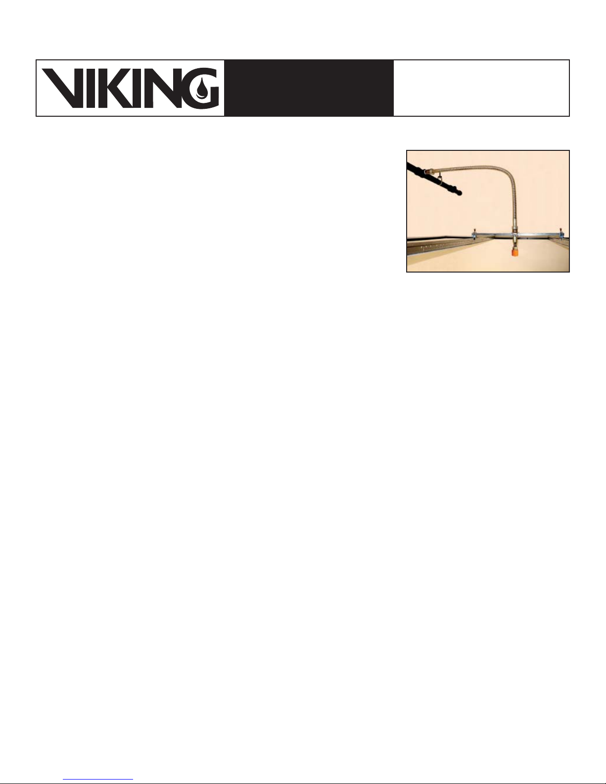
Viking Model VKFD25U Flexible Sprinkler Drop Assemblies are complete assemblies
intended for installation into commercial suspended ceilings with medium to heavy
support tee bars as described in ASTM C635 and C636. The hose assembly includes
25 mm diameter corrugated stainless steel flexible hose. The hose assembly includes
an inlet nipple 1” NPT for attachment to the sprinkler system branch piping, a special
outlet reducer fitting with a straight outlet, pre-assembled with a ½” NPT sprinkler. Also
included is a support bar and brackets, which secure the complete flex sprinkler drop assembly to a medium or heavy duty commercial suspended ceiling support rail system.
Specific Viking sprinklers are pre-packaged (10) units per carton factory installed on to
the outlet reducer fittings along with the outlet reducer support bracket and are pres-
sure tested. Refer to Table 1 for sprinkler VK302 and VK462 available pre-packaged
as Flexible Sprinkler Drop Assemblies. Frame style sprinkler VK302 is available with
the slip-on Model E-1 or threaded Model E-2 Adjustable Recessed Escutcheon, or with
the Model F-1 Adjustable Escutcheon.
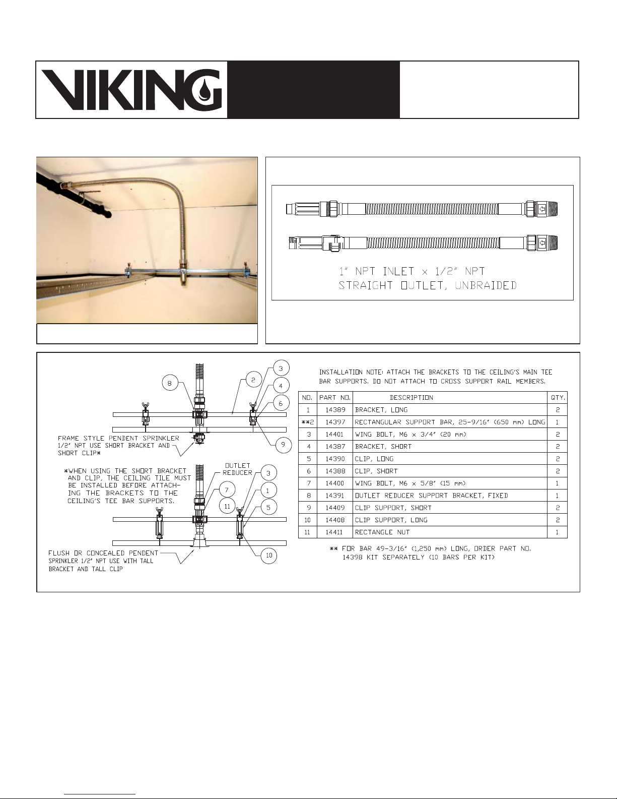
Rail support brackets are included; short brackets for use with frame style sprinkler VK302 and tall brackets for use with concealed
style sprinkler VK462. The support bracket system (see Figure 3) locates and secures the sprinkler in the required position within
the ceiling system. Note: When using short brackets, the ceiling tile must be installed before attaching the brackets to the ceiling’s
main tee bar supports. Tall brackets are used for typical concealed sprinklers; the mounting bracket system and special outlet fittings provide a generous amount of adjustment both laterally and vertically for flush and precise sprinkler installation. Note: The
brackets must be attached to the ceiling’s main tee bar supports, not to the cross support rail members.
The unique assembly of the Viking Flexible Sprinkler Drop to the piping system and the outlet sprinkler fitting is made with a slip nut
and seal design that allows assembly after forming the flex hose to proper installation shape, and the inlet and outlet end connections
are securely in place. This prevents twisting of the flex sprinkler drop during installation and provides a secure leak-tight assembly.
The Viking Model VKFD25U Pre-Assembled Flexible Sprinkler Drop standard available assembly length is 39-3/8” with a straight
outlet fitting and a ½” NPT sprinkler connection. Upon special request, Viking Flexible Sprinkler Drops can be manufactured to the
following lengths: 27-9/16”, 59”, or 71”. Delivery times for special request items are extended; consult your Viking distributor for
availability and delivery.
Viking Flexible Sprinkler Drops provide several installation or retrofit benefits compared to rigid sprinkler drops:
SPRINKLER DROP
ASSEMBLIES
Model VKFD25U Flexible Sprinkler Drop
(Shown with a Viking Concealed Sprinkler)
(UNBRAIDED)
More efficient manpower
•
Improved performance and installation quality
•
Precise and flush sprinkler location
•
Flexible installation for seismic or vibrating applications
•
Flexible installation for fast track construction projects
•
Corrosion-resistant materials
•
Fewer tools required for installation
•
100% factory tested
•
Meets NFPA, EN, and LPC guidelines
•
Approved for use with suspended ceilings with medium- and heavy-duty load grids with Tee bar design per ASTM C635 and 636
•
2. LISTINGS AND APPROVALS
cULus Listed: Category VENF
Refer to Design Criteria on page 138l for cULus Listing requirements that must be followed.
Also refer to specific sprinkler technical data pages for sprinkler listings and other technical information.
Form No. F_091509
New page 138g-l, issued September 17, 2009.
Page 2
Sprinkler 138h
September 17, 2009
MODEL VKFD25U
PRE-ASSEMBLED FLEXIBLE
TECHNICAL DATA
The Viking Corporation, 210 N Industrial Park Drive, Hastings MI 49058
Telephone: 269-945-9501 Technical Services: 877-384-5464 Fax: 269-818-1680 Email: [email protected]
3. TECHNICAL DATA
Specifi cations:
Available since 2010.
Hose tube diameter: 25 mm outside diameter
•
Standard Length: 39-3/8”
•
Inlet 1” NPT, male pipe threads.
•
Outlet reducer straight with 1/2” NPT, female thread. See Figures 1-3.
•
Corrugated tube is annealed after forming to insure relief of all material stresses and removal of all scale.
•
Maximum Working Pressure = 200 PSI (13.8 bar)
•
Test Pressure = 300 PSI (21 bar)
•
Approved for wet and dry systems as noted in NFPA 13
•
Maximum ambient temperature: 225 °F (107 °C) EPDM seal
•
WARNING: Refer to the sprinkler technical data page, as the temperature rating and maximum pressure rating of the
sprinkler may be different than the Flexible Sprinkler Drop.
Minimum bend radius: 4” (102 mm) for cULus Listing
•
Material Standards:
Flexible Tube: UNS-S30400 Stainless Steel
Outlet Reducer (Straight): SPPS Steel (ASTM A53 EA) with yellow zinc plating
Inlet Nipple: SPPS Steel (ASTM A53 EA) with yellow zinc plating
Seal: EPDM
Slip Nut: SS41 (ASTM A283 D) Steel with zinc plating
Support Brackets (all): SS41 (ASTM A283 D) Steel with zinc plating
Support Bar: SS41 (ASTM A283 D) Steel with zinc plating
Insulating Collar: Nylon 66
The Web site may include a more recent
SPRINKLER DROP
ASSEMBLIES
Viking Technical Data may be found on
The Viking Corporation’s Web site at
http://www.vikinggroupinc.com.
edition of this Technical Data Page.
(UNBRAIDED)
Ordering Information: (Also refer to the current Viking price list.)
Flexible Sprinkler Drop Assembly Kits Pre-Assembled with Viking Sprinklers: Outlet reducer support bracket (bracket, square nut,
and wing bolt) assembled over straight outlet fitting, sprinklers (see Table 1) installed and leak tested into the outlet fitting as specified, (10) per kit.
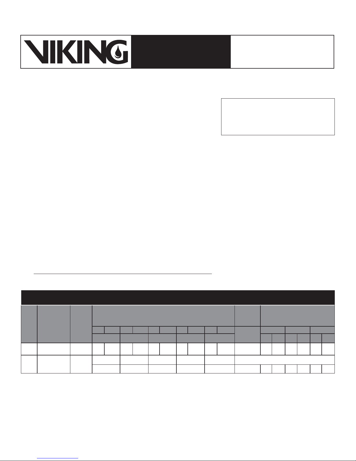
TABLE 1
SPRINKLERS AVAILABLE TO ORDER AS PRE-ASSEMBLED MODEL VKFD25U UNBRAIDED FLEXDROP KITS
Add
Unbraided
Flex Hose
Suffix
39-3/8”
length
SIN
VK302
VK462
Sprinkler
Description
®
Microfast
Pendent K5.6
Pendent K5.6
QR
Mirage®
Concealed
Sprinkler
Base
Part No.
1
Chr Wht Chr Wht Chr Wht Chr Wht Chr Wht
135°F (57°C)155°F (68°C)175°F (79°C)200°F (93°C)
06662B FA MA/W FB MB/W FD MD/W FE ME/W FG MG/W 16038-10 1F 1W 2F 2W 3F 3W
13503A
135°F (57°C) 155°F (68°C) 175°F (79°C) 200°F (93°C) 286°F (141°C)
-- B D E -- 16038-10 -- -- -- -- -- --
Add Finish and Temperature Suffix
286°F
(141°C)
Instructions:
1. For frame style sprinkler VK302, add the sprinkler Finish and Temperature Rating Suffix to the Sprinkler Base Part No.
A. For Chrome sprinkler rated 135°F (57°C): Add the suffix “FA”. For White sprinkler rated 135°F (57°C): Add the suffix “MA/W”
B. For Chrome sprinkler rated 155°F (68°C): Add the suffix “FB”. For White sprinkler rated 155°F (68°C): Add the suffix “MB/W”
C. For Chrome sprinkler rated 175°F (79°C): Add the suffix “FD”. For White sprinkler rated 175°F (79°C): Add the suffix “MD/W”
D. For Chrome sprinkler rated 200°F (93°C): Add the suffix “FE”. For White sprinkler rated 200°F (93°C): Add the suffix “ME/W”
E. For Chrome sprinkler rated 286°F (141°C): Add the suffix “FG”. For White sprinkler rated 286°F (141°C): Add the suffix “MG/W”
2. Add the Flex Hose Suffix: “/16038-10”
Add Escutcheon Suffix
(If Applicable)
Model E-1 Model E-2 Model F-1
Chr Wht Chr Wht Chr Wht
Page 3
September 17, 2009
Sprinkler 138i
MODEL VKFD25U
PRE-ASSEMBLED FLEXIBLE
TECHNICAL DATA
The Viking Corporation, 210 N Industrial Park Drive, Hastings MI 49058
Telephone: 269-945-9501 Technical Services: 877-384-5464 Fax: 269-818-1680 Email: [email protected]
3. For frame style sprinkler VK302 (temperature ratings 135 °F-200 °F only), add the Escutcheon and Escutcheon Finish Suffix:
A. For frame style sprinkler VK302 with the Model E-1 Recessed Escutcheon: Add the suffix “/1F” for Chrome or “/1W” for White
B. For frame style sprinkler VK302 with Model E-2 Recessed Escutcheon: Add the suffix “/2F” for Chrome or “/2W” for White
C. For frame style sprinkler VK302 with the Model F-1 Adjustable Escutcheon: Add the suffix “/3F” for Chrome or “/3W” for White
Examples:
1. Model VKFD25U Flexible Sprinkler Drop Assembly for concealed sprinkler VK462 with a 155 °F/68 °C temperature rating = Part
Number 13503AB/16038-10.
2. Model VKFD25U Flexible Sprinkler Drop Assembly with frame style sprinkler VK302 with a 155 °F/68 °C temperature rating,
chrome finish, and the Model E-2 Escutcheon = Part Number 06662BFB/16038-10/2F.
Note for Concealed Sprinkler VK462: The cover plate must be ordered separately (refer to the sprinkler technical data
page and Viking’s current price list).
NOTE: Hose assemblies ordered from Viking only come with straight outlet as standard.
Available to Order Separately:
Optional 4” Bend Radius Gauge Tool Part No. 15450 (plastic)
Optional 4” Fixed Radius Clip Part No. 14403 (plastic)
The Following Kits are Available for Replacement Components:
Note: These kits may be ordered in addition to the above for replacing components as required. A 49-3/16” (1,250 mm) long support
bar is available when the main support beams are spaced at 4 ft. (1,219 mm). These must be ordered separate from the standard
lexible Sprinkler Drop Assembly.
SPRINKLER DROP
ASSEMBLIES
(UNBRAIDED)
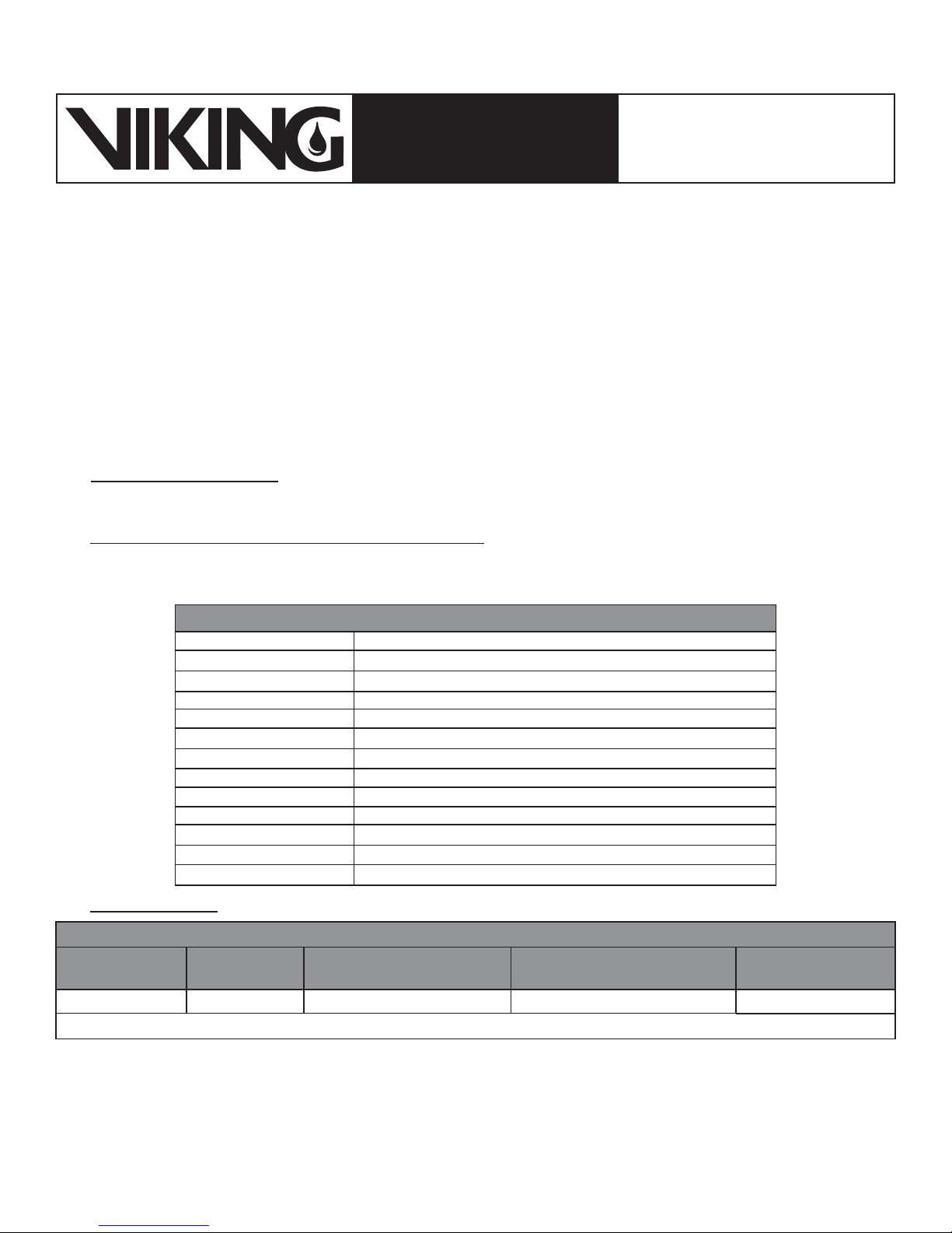
TABLE 2:
16042 1/2” x 25 mm hose straight outlet fitting kit (10) / package
14387 Short rail bracket kit (20) / package
14388 Short rail clip kit (20) / package
14409
14389 Tall rail bracket kit (20) / package
14390 Tall rail clip kit (20) / package
14408 Tall rail clip support (20) / package
14400 Thumb screws outlet fitting M6 x 15 mm long (12) per kit
14401 Thumb screws rail brackets M6 x 20 mm long (25) per kit
16043 EPDM Seals for 25 mm hose assembly (20) / package
14411 Rectangle nut for sprinkler outlet bracket (12) / package
14391 Outlet reducer support bracket (10) / package
16040 Inlet nipple (10) / package
KITS AVAILABLE FOR REPLACEMENT COMPONENTS
Short rail clip support (20) / package
Friction Loss Data:
TABLE 3: MODEL VKFD25U FRICTION LOSS DATA WITH 4” (102 mm) MINIMUM BEND RADIUS
Outlet Size
1/2” 39-3/8“* 52 ft 15.8 m 2
*Indicates standard Viking offering. Other hose lengths are available-contact Viking Technical Services at 877-384-5464 for friction loss data.
Hose Length
with Fittings
Equivalent Length of UL 1”
Schedule 40 Pipe (ft.)
Equivalent Length of UL
1” Schedule 40 Pipe (m)
Maximum Number
of 90° Bends
Page 4
Sprinkler 138j
September 17, 2009
MODEL VKFD25U
PRE-ASSEMBLED FLEXIBLE
TECHNICAL DATA
The Viking Corporation, 210 N Industrial Park Drive, Hastings MI 49058
Telephone: 269-945-9501 Technical Services: 877-384-5464 Fax: 269-818-1680 Email: [email protected]
SPRINKLER DROP
ASSEMBLIES
(UNBRAIDED)
Figure 1: Flexible Sprinkler Drop Installed
Figure 3: Flexible Sprinkler Drop Support System
Figure 2: Flexible Sprinkler Drop - Drawing
4. INSTALLATION
Viking Flexible Sprinkler Drop Assemblies are manufactured and tested to meet the latest rigid requirements of the approving
agencies. They are designed and tested to be installed in accordance with the Approved and Listed installation instructions as
provided with the product and the recognized installation standards. Deviations from these standards or any alterations to the support system or sprinkler after leaving the factory including, but not limited to painting, plating, coating or modification may render
the sprinkler inoperative or the support system non-compliant, automatically nullifying the approvals and any guarantee made by
The Viking Corporation. The use of certain types of sprinklers may be limited due to occupancy and hazard. Refer to the Authority
Having Jurisdiction prior to installation.
For complete installation instructions for this product, please refer to the Viking Flex Drop Installation and Design Manual, Form
No. F_112107.
NOTE: Keep sprinklers with protective shields or caps contained within the shields or caps during installation and testing, and any
time the sprinkler is shipped or handled.
The sprinklers are factory installed onto the outlet reducer fittings along with the outlet reducer support bracket and are pressure
tested.
Page 5
September 17, 2009
Sprinkler 138k
MODEL VKFD25U
PRE-ASSEMBLED FLEXIBLE
TECHNICAL DATA
The Viking Corporation, 210 N Industrial Park Drive, Hastings MI 49058
Telephone: 269-945-9501 Technical Services: 877-384-5464 Fax: 269-818-1680 Email: [email protected]
Remove plastic protective sprinkler caps or bulb shields AFTER the ceiling finish work is completed where the sprinkler
is installed and there no longer is a potential for mechanical damage to the sprinkler operating elements. To remove the
bulb shields, simply pull the ends of the shields apart where they are snapped together. To remove caps from frame style sprinklers, turn the caps slightly and pull them off the sprinklers. SPRINKLER CAPS OR BULB SHIELDS MUST BE REMOVED FROM
SPRINKLERS BEFORE PLACING THE SYSTEM IN SERVICE! Retain a protective cap or shield in the spare sprinkler cabinet.
For concealed style sprinklers, the cover plate assembly can now be installed onto the sprinkler.
a. Remove the cover from the protective box, taking care not to damage the cover plate assembly.
b. From below the ceiling, gently place the base of the cover plate assembly over the sprinkler protruding through the ceiling
opening.
c. Push the cover plate assembly onto the sprinkler until the unfinished brass flange of the cover plate base touches the ceiling.
d. Available cover plate adjustment is ½” (12.7 mm) +/- 1/4” (6.4 mm).
For frame style sprinklers with the Model E-1 or E-2 Escutcheon, or with the Model F-1 Escutcheon, press on or thread on the outer
escutcheon cup until the flanges touch the surface of the ceiling.
a. With the E-1 or E-2 Escutcheon, the maximum recess is ½” (12.7 mm). Note: The face of the escutcheon adapter may ex-
tend up to 11/32” (8.7 mm) beyond the edge of the escutcheon cup, resulting in 27/32” (21.4 mm) total adjustment range.
If it is necessary to remove the entire sprinkler unit, the system must be taken out of service. See section 6. INSPECTIONS, TESTS
AND MAINTENANCE and follow all warnings and instructions.
SPRINKLER DROP
ASSEMBLIES
(UNBRAIDED)
5. OPERATION
Refer to the sprinkler technical data page for the sprinkler model used with the Flexible Sprinkler Drop Assembly.
6. INSPECTIONS, TESTS AND MAINTENANCE
NOTICE: The owner is responsible for maintaining the fire protection system and devices in proper operating condition. For mini-
mum maintenance and inspection requirements, refer to the latest edition of Viking technical data and the NFPA standard that
describes care and maintenance of sprinkler systems. The Authority Having Jurisdiction may have additional maintenance, testing,
and inspection requirements that must be followed.
A. Sprinklers must be inspected on a regular basis for corrosion, mechanical damage, obstructions, paint, etc. The frequency of
inspections may vary due to corrosive atmospheres, water supplies, and activity around the device.
B. Sprinklers that have been field painted or mechanically damaged must be replaced immediately. Sprinklers showing signs of
corrosion shall be tested and/or replaced immediately as required. Installation standards require sprinklers to be tested and, if
necessary , replaced after a specified term of service. Refer to the installation standards (e.g., NFPA 25) and the Authority Having
Jurisdiction for the specified period of time after which testing and/or replacement is required. Sprinklers that have operated
cannot be reassembled or re-used, but must be replaced. When replacement is necessary, use only new sprinklers.
C. The sprinkler discharge pattern is critical for proper fire protection. Therefore, nothing should be hung from, attached to, or other-
wise obstruct the discharge pattern. All obstructions must be immediately removed or, if necessary, additional sprinklers installed.
D. When replacing existing sprinklers, the system must be removed from service. Refer to the appropriate system description and/
or valve instructions. Prior to removing the system from service, notify all Authorities Having Jurisdiction. Consideration should
be given to employment of a fire patrol in the affected area.
1. Remove the system from service, drain all water, and relieve all pressure on the piping.
2. Using the special sprinkler wrench, remove the old sprinkler and install the new unit. Care must be taken to ensure that
the replacement sprinkler is the proper model and style, with the appropriate orifice size, temperature rating, and response
characteristics. A fully stocked spare sprinkler cabinet should be provided for this purpose.
3. Place the system back in service and secure all valves. Check for and repair all leaks.
E. Sprinkler systems that have been subjected to a fire must be returned to service as soon as possible. The entire system must
be inspected for damage, and repaired or replaced as necessary. Sprinklers that have been exposed to corrosive products of
combustion or high ambient temperatures, but have not operated, should be replaced. Refer to the Authority Having Jurisdiction
for minimum replacement requirements.
7. AVAILABILITY
Viking Flexible Sprinkler Drop Assemblies are available through a network of domestic and international distributors. See The Viking
Corporation web site for the closest distributor or contact The Viking Corporation.
8. GUARANTEE
For details of warranty, refer to Viking’s current list price schedule or contact Viking directly.
Page 6
Sprinkler 138l
September 17, 2009
MODEL VKFD25U
PRE-ASSEMBLED FLEXIBLE
TECHNICAL DATA
The Viking Corporation, 210 N Industrial Park Drive, Hastings MI 49058
Telephone: 269-945-9501 Technical Services: 877-384-5464 Fax: 269-818-1680 Email: [email protected]
DESIGN CRITERIA
cULus Listing Requirements:
• Approved for use in ceilings with medium and heavy load grids (ASTM C635 and C636).
• Compatible with Viking CPVC BlazeMaster® sprinkler systems.
• Meets NFPA 13, NFPA 13D and NFPA 13R guidelines and EN12845.
• Intended for use in wet or dry systems.
• The maximum permissible number of bends is (2) x 90° for 39-3/8“ lengths at the manufacturer’s specified bend radius of 4” (102 mm) for
cULus.
• In suspended ceiling, Viking Flexible Sprinkler Drops must be installed in accordance with Viking Flex Drop Installation and Design Manual, Form
No. F_112107.
• In suspended ceilings, outlet reducer must be secured to the ceiling support system with brackets supplied.
Hydraulic calculations for NFPA systems must include the values in Table 3 on page 138j using the maximum number of bends that includes
the inlet and outlet fittings as indicated. Authorities Having Jurisdiction will require proper hydraulic calculations and inspect for proper
bend radii and maximum quantity of bends as indicated in the table. Refer to the Viking Flex Drop Installation and Design Manual, Form No.
F_112107, for proper application and installation of Flexible Sprinkler Drops.
NOTE: Refer to the specific sprinkler data page for the sprinkler model used with the Flexible Sprinkler Drop.
CAUTIONS:
• Minimum Inside Bend Radius: 4” (102 mm) Static cULus unbraided
• Maximum Sprinkler K-Factor: 5.6 U.S. (80.6 metric)
• Maximum Number of Bends per Hose: Refer to Table 3 on page 138j.
• Repeated bending of one portion of the flexible tube before installation may cause breakage or loss of resisting pressure.
• When using concealed sprinklers, they must be installed in neutral or negative pressure plenums only.
SPRINKLER DROP
ASSEMBLIES
(UNBRAIDED)
IMPORTANT: Always refer to Bulletin Form No. F_091699 - Care and Handling of Sprinklers. Also refer to the
appropriate sprinkler data page. Viking sprinklers and Flexible Sprinkler Drops are designed to be installed
in accordance with the latest edition of Viking technical data, the latest standards of NFPA, FM Global, LPCB,
APSAD, VdS or other similar organizations, and also with the provisions of governmental codes, ordinances,
and standards whenever applicable. The use of certain types of sprinklers may be limited due to occupancy and
hazard. Refer to the Authority Having Jurisdiction prior to installation.
Form No. F_091509
New page 138g-l, issued September 17, 2009.
 Loading...