

Page 1
QUICK RESPONSE
TECHNICAL DATA
EXTENDED COVERAGE
CONCEALED HSW
SPRINKLER VK680 (K8.0)
The Viking Corporation, 210 N Industrial Park Drive, Hastings MI 49058
Telephone: 269-945-9501 Technical Services: 877-384-5464 Fax: 269-818-1680 Email: [email protected]
Visit the Viking website for the latest edition of this technical data page www.vikinggroupinc.com.
1. DESCRIPTION
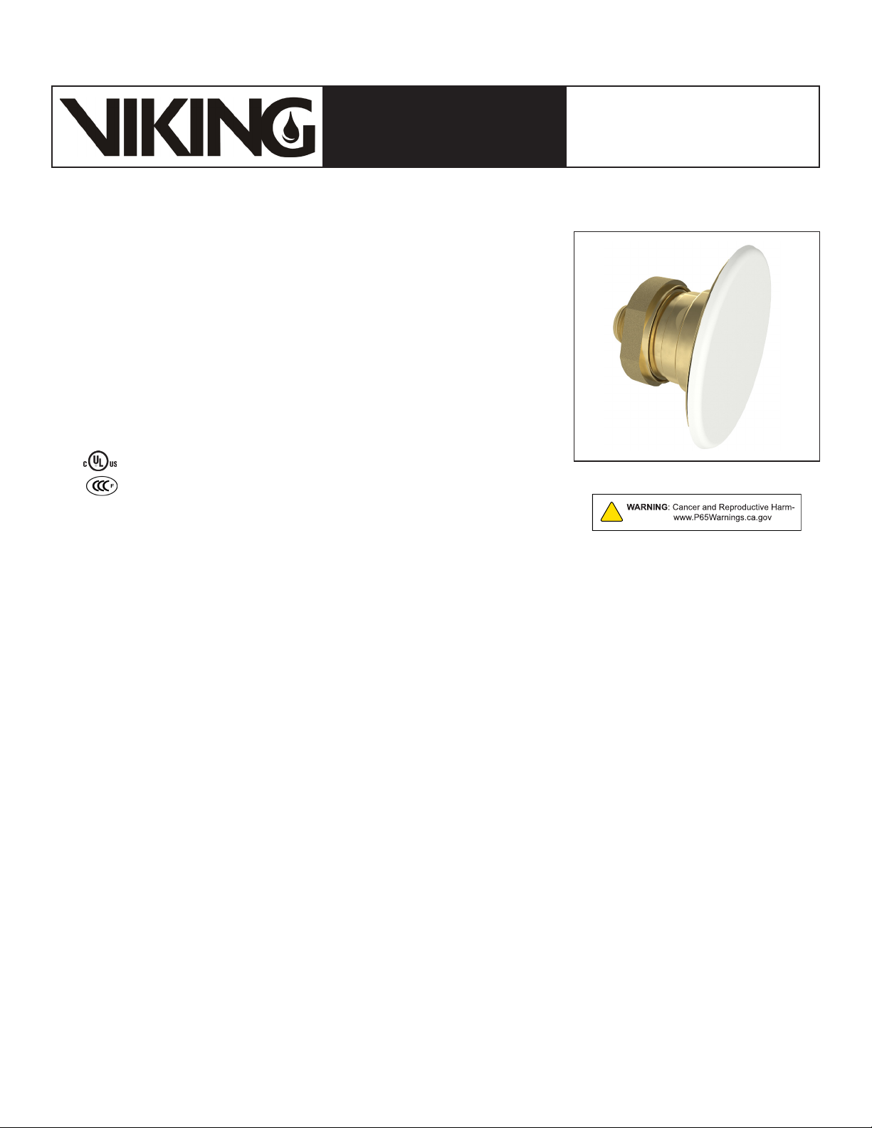
Viking QREC Concealed Horizontal Sidewall Sprinkler VK680 is a small highsensitivity solder link and lever sprinkler designed for installation on concealed pipe
systems, where the appearance of a smooth wall is desired. The fast response
operating element and special flow shaper characteristics meet the challenges of
quick response extended coverage standards.
The sprinkler is hidden from view by a low profile, small diameter cover plate installed
flush to the wall. The cover plate is available in several decorative finishes to meet
design requirements. The two-piece design allows installation and testing of the
sprinkler prior to installation of the cover plate. After the system has been tested and
wall finish has been applied, the push-on design of the cover plate assembly allows
easy installation of the cover plate with up to 1/4” (6.4 mm) adjustment.
2. LISTINGS AND APPROVALS
cULus Listed: Category VNIV
CCCF Approved: Approved by the China Certification Center for Fire
Products (CCCF)
Refer to the Approval Chart and Design Criteria on this Technical Data Page
for cULus Listing requirements that must be followed.
For Light Hazard Occupancies Only
Page 1 of 5
3. TECHNICAL DATA
Specications:
Available since 2011.
Minimum Operating Pressure: 7 psi (0.5 bar)
Maximum Working Pressure: 175 psi (12 Bar). Factory tested hydrostatically to 500 psi (34.5 bar).
Thread size: 3/4” (20 mm) NPT
Nominal K-Factor: 8.0 U.S. (115.2 metric†)
† Metric K-factor measurement is in Bar. When pressure is measured in kPa, divide the metric K-factor shown by 10.0.
Available Cover Plate Horizontal Adjustment: 1/4” (6.4 mm)
Overall Length (Sprinkler Body): 2” (50.8 mm)
Patents Pending
Material Standards:
Sprinkler Body: QM Brass and Brass UNS-C84400
Belleville Spring Sealing Assembly: Nickel Alloy, coated on both sides with Teflon Tape
Seat: Brass UNS-C31400
Deflector Ring: Brass UNS-C23000
Deflector Pins: Stainless Steel UNS-S30200
Halo: Brass UNS-C31400 or Phosphor Bronze UNS-C51000
Flow Shaper: Phosphor Bronze UNS-C51000
Lever Bar Ring: Brass UNS-C31400 or Brass UNS-C84400
Compression Screw: 18-8 Stainless Steel
Fusible Link Assembly: Nickel Alloy and Eutectic Solder
Fusible Link Levers: Stainless Steel UNS-S31600
Guide Pin: Stainless Steel UNS-S43000
Shipping Cap: Polyethylene
Cover Assembly Materials:
Cover Plate Assembly: Copper UNS-C11000 and Brass UNS-C26800
Spring: Beryllium Nickel
Solder: Eutectic
Form No. F_050611 18.10.25 Rev 17.1.P65
Replaces Form No. F_050611 Rev 17.1
(Added P65 Warning.)
Page 2
Page 2 of 5
F
A
C
T
O
R
Y
A
P
P
L
I
E
D
C
U
S
T
O
M
P
A
I
N
T
C
O
L
O
R
QUICK RESPONSE
TECHNICAL DATA
EXTENDED COVERAGE
CONCEALED HSW
SPRINKLER VK680 (K8.0)
The Viking Corporation, 210 N Industrial Park Drive, Hastings MI 49058
Telephone: 269-945-9501 Technical Services: 877-384-5464 Fax: 269-818-1680 Email: [email protected]
Visit the Viking website for the latest edition of this technical data page www.vikinggroupinc.com.
Ordering Information: (Also refer to the current Viking price list.)
Viking QREC Concealed HSW Sprinkler VK680 and Cover Plate Assembly must be ordered separately:
Sprinkler: Part No. 17114AC (includes a 165 °F (74 °C) temperature rated sprinkler with a protective plastic cap covering the unit).
Cover Plate Assembly: Base Part No. 16207 (3-5/16” diameter)
Specify finish and temperature rating of the cover plate assembly by adding the appropriate suffixes for the finish and the cover
temperature rating to the base part number:
Finish Suffix: Polished Chrome = F, Painted White = M-/W, Painted Ivory = M-/I, Painted Black = M-/B
Temperature Suffix: 135 °F (57 °C) = A
For example, cover 16207 with a Polished Chrome finish and a 135 °F (57 °C) temperature rating = 16207FA.
Available Finishes And Temperature Ratings: Refer to Table 1.
Accessories: (Also refer to the Viking website.)
Sprinkler Wrenches**:
A. Heavy Duty Wrench Part No. 16208W/R (available since 2010)
B. Head Cabinet Wrench Part Number 16267*** (available since 2010)
C. Optional Large Concealed Cover Plate Installer Tool Part No. 14867 (available since 2007)
**Requires a ½” ratchet (not available from Viking).
***Ideal for sprinkler cabinets.
Sprinkler Cabinet: Part No. 01731A (available since 1971)
4. INSTALLATION
Refer to appropriate NFPA Installation Standards.
5. OPERATION
During fire conditions, when the temperature around the sprinkler approaches its operating temperature, the cover plate detaches.
Continued heating of the exposed sprinkler causes the fusible element to disengage, releasing the sealing assembly. Water flowing
through the sprinkler orifice strikes the flow shaper, forming a uniform spray pattern to extinguish or control the fire.
6. INSPECTIONS, TESTS AND MAINTENANCE
Refer to NFPA 25 for Inspection, Testing and Maintenance requirements.
7. AVAILABILITY
The Viking Model VK680 Sprinkler is available through a network of domestic and international distributors. See The Viking
Corporation web site for the closest distributor or contact The Viking Corporation.
8. GUARANTEE
For details of warranty, refer to Viking’s current list price schedule or contact Viking directly.
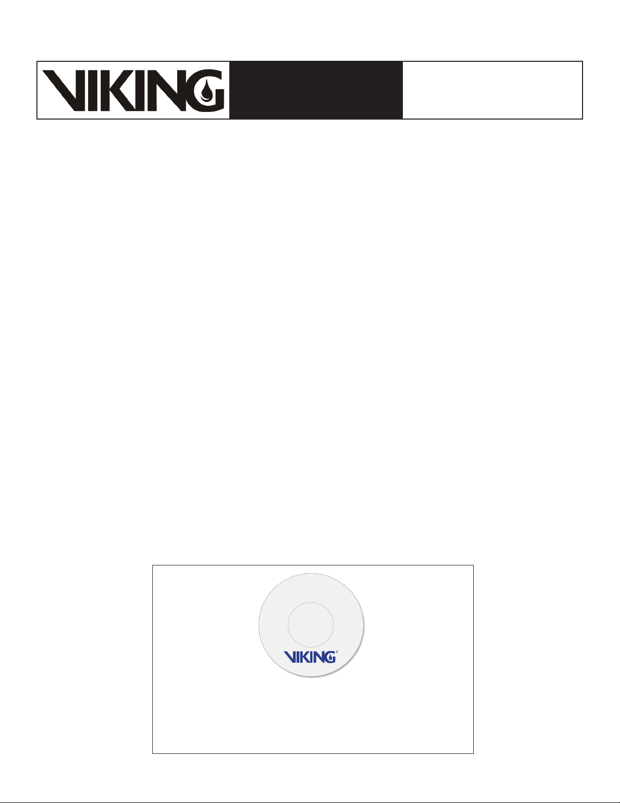
All custom color painted cover plates will have an identifying label affixed
Form No. F_050611 18.10.25 Rev 17.1.P65
to the inside of the cover that indicates the custom color and will have a
Figure 1: Identification of Custom Paint for Concealed Covers
representative sample (a paint dot) of the paint on the label.
Page 3
Page 3 of 5
QUICK RESPONSE
TECHNICAL DATA
EXTENDED COVERAGE
CONCEALED HSW
SPRINKLER VK680 (K8.0)
The Viking Corporation, 210 N Industrial Park Drive, Hastings MI 49058
Telephone: 269-945-9501 Technical Services: 877-384-5464 Fax: 269-818-1680 Email: [email protected]
Visit the Viking website for the latest edition of this technical data page www.vikinggroupinc.com.
TABLE 1: AVAILABLE SPRINKLER TEMPERATURE RATINGS AND FINISHES
Sprinkler Temperature
Classification
Ordinary 165 °F (74 °C) 100 °F (38 °C) 135 °F (57 °C) 16207
Cover Plate Finishes: Polished Chrome, Painted White, Painted Ivory, or Painted Black
1
The sprinkler temperature rating is stamped on the inlet.
2
Based on NFPA-13. Other limits may apply, depending on fire loading, sprinkler location, and other requirements of the Authority Having Jurisdiction.
Refer to specific installation standards.
3
Part number shown is the base part number. For complete part number, refer to current Viking price list schedule.
Sprinkler Nominal
Temperature Rating
Maximum Ambient
1
Ceiling Temperature
Footnotes
Temperature Rating of the
2
Required Cover Assembly
Cover Plate
Base Part Number
3
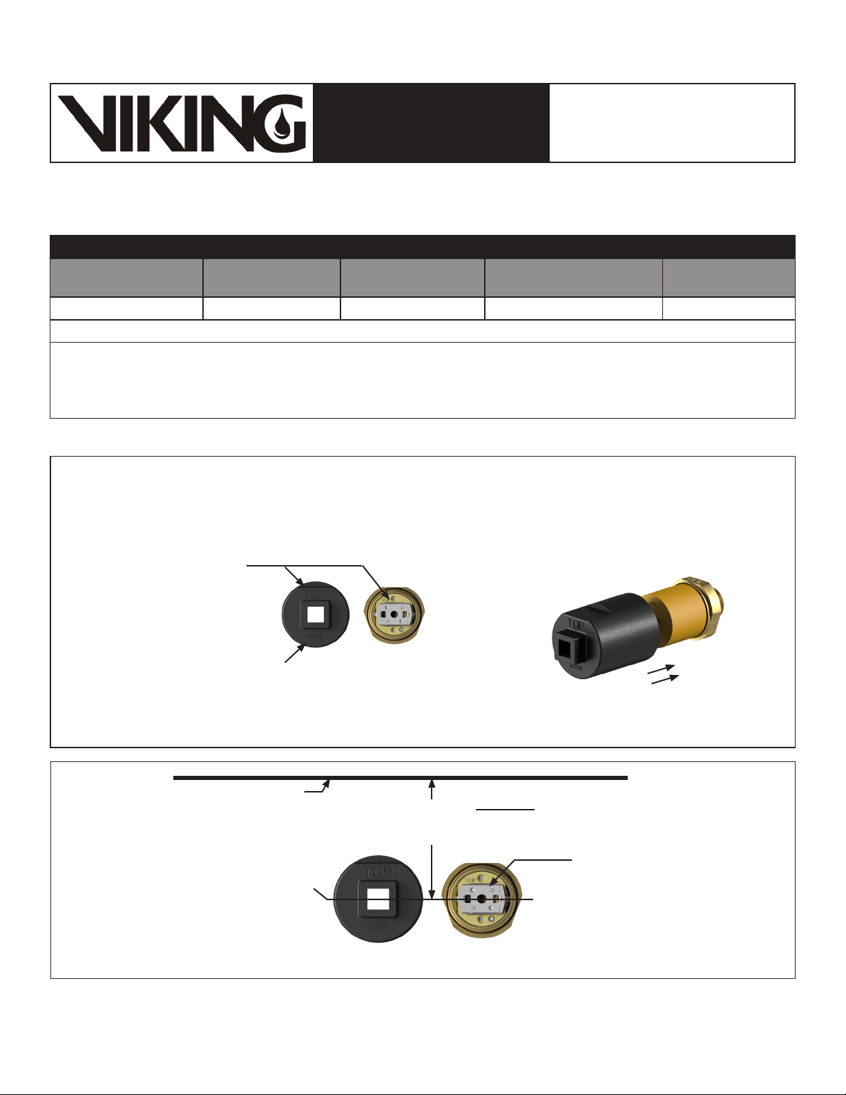
The internal design of the
sprinkler wrench is shaped
to fit over the sprinkler and
protective cap to ensure that
the top of the wrench will be
oriented in the same direction
as the top of the sprinkler
deflector.
Figure 2: Sprinkler VK680 Installation and Correct Use of Wrench
Measure from the
centerline of the
sprinkler to the ceiling.
Centerline of sprinkler
(Corresponds with the
centerline of the wrench)
wrench
CEILING
shown then slide the wrench over the
sprinkler body and the protective cap.
Sprinkler bodySprinkler
Must be located with the centerline
of the sprinkler 4-3/8” to 12-3/8”
(112 to 314 mm) below the ceiling.
Orient the sprinkler and wrench as
The top of the sprinkler
is marked “TOP”.
Keep the top of the
element oriented parallel
to the ceiling.
Figure 3: Sprinkler VK680 Correct Deflector Orientation
Form No. F_050611 18.10.25 Rev 17.1.P65
Page 4
Page 4 of 5
QUICK RESPONSE
TECHNICAL DATA
EXTENDED COVERAGE
CONCEALED HSW
SPRINKLER VK680 (K8.0)
The Viking Corporation, 210 N Industrial Park Drive, Hastings MI 49058
Telephone: 269-945-9501 Technical Services: 877-384-5464 Fax: 269-818-1680 Email: [email protected]
Visit the Viking website for the latest edition of this technical data page www.vikinggroupinc.com.
Sprinkler Base
Part Number
1
NPT Thread Size Nominal K-Factor
Inches mm U.S. metric
Maximum Water
Working Pressure
2
psi (bar) Inches mm
Overall Length
(Sprinkler Body)
17114AC 3/4 -- 8.0 115.2 175 (12) 2 51
NOTICE - Product Below - ONLY for CCCF Approval
20379AC -- 20 mm 8.0 115.2 175 (12) 2 51
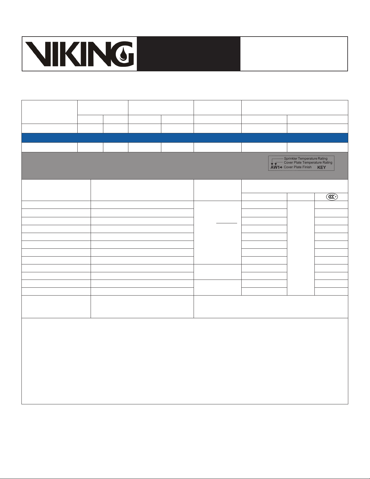
Approval Chart
QREC Concealed HSW Sprinkler VK680
For installation below smooth, flat, horizontal ceilings only.
Maximum Areas of
Coverage
4
Minimum Water Supply Requirements
(Width x Throw)
14’ x 22’ (4.3 m x 6.7 m) 31 gpm @ 15.0 psi (117.3 L/min @ 1.04 Bar)
16’ x 16’ (4.9 m x 4.9 m) 26 gpm @ 10.6 psi (98.4 L/min @ 0.73 Bar) AX1 AX1
16’ x 18’ (4.9 m x 5.5 m) 29 gpm @ 13.1 psi (109.8 L/min @ 0.91 Bar) AX1 AX1
16’ x 20’ (4.9 m x 6.1 m) 32 gpm @ 16.0 psi (121.1 L/min @ 1.1 Bar) AX1 AX1
16’ x 22’ (4.9 m x 6.7 m) 36 gpm @ 20.3 psi (136.3 L/min @ 1.4 Bar) AX1 AX1
18’ x 18’ (5.5 m x 5.5 m) 33 gpm @ 17.0 psi (124.9 L/min @ 1.2 Bar) AX1 AX1
18’ x 20’ (5.5 m x 6.1 m) 36 gpm @ 20.3 psi (136.3 L/min @ 1.4 Bar) AX1 AX1
18’ x 22’ (5.5 m x 6.7 m) 40 gpm @ 25 psi (151.4 L/min @ 1.72 Bar) AX1 AX1
14’ x 24’ (4.3 m x 7.3 m) 34 gpm @ 18.1 psi (128.7 L/min @ 1.25 Bar)
16’ x 24’ (4.9 m x 7.3 m) 39 gpm @ 23.8 psi (147.6 L/min @ 1.64 Bar) AX1 --
14’ x 24’ (4.3 m x 7.3 m) 35 gpm @ 19.2 psi (132.5 L/min @ 1.32 Bar)
16’ x 24’ (4.9 m x 7.3 m) 40 gpm @ 25 psi (151.4 L/min @ 1.72 Bar) AX1 --
Sprinkler Temperature
Rating
A - 165 °F (74 °C)
Cover Assembly
Temperature Rating
X - 135 °F (57 °C) cover 16207
For Light Hazard Occupancies Only.
Sprinkler Distance
4
Below the Ceiling
Must be installed
with the centerline
of the sprinkler
4-3/8” to 12-3/8”
(112 to
314 mm) below the
ceiling.
4-3/8” (112 mm)
to 6-3/8” (162 mm)
6-3/8” (162 mm)
to 12-3/8” (314 mm)
1
1 - Polished Chrome, Painted White7, Painted Ivory7, or Painted Black
Listings and Approvals
(Refer also to Design Criteria on page 4.)
5
cULus
NYC
AX1
AX1 --
See Footnote 6.
AX1 --
Cover Plate Finishes
3
AX1
7
1
Part number shown is the base part number. For complete part number, refer to current Viking price list schedule.
2
Metric K-factor measurement shown is when pressure is measured in Bar. When pressure is measured in kPa, divide the metric K-factor shown by 10.0.
3
This chart shows the listings and approvals available at the time of printing. Other approvals may be in process. Check with the manufacturer for any
additional approvals.
4
For areas of coverage smaller than shown, use the “Minimum Water Supply Requirement” for the next larger area listed. Flows and pressures listed
are per sprinkler.
5
Listed by Underwriter’s Laboratories, Inc. for use in the U.S. and Canada. cULus Listings are limited to Light Hazard occupancies with smooth, flat,
Footnotes
horizontal ceilings only. Always install horizontal sidewall sprinkler VK680 with the top of the sprinkler element oriented parallel with the ceiling. Refer
to Figure 3 on page 4.
6
Meets New York City requirements, effective July 1, 2008.
7
Painted finish consists of Polyester Baked Enamel. Other paint colors are available on request with the same listings as the standard paint colors.
Listings and approvals apply for any paint manufacturer. Contact Viking for additional information.
NOTE: Custom colors are indicated on a label inside the cover assembly. Refer to Figure 1.
Form No. F_050611 18.10.25 Rev 17.1.P65
Page 5
Page 5 of 5
QUICK RESPONSE
TECHNICAL DATA
EXTENDED COVERAGE
CONCEALED HSW
SPRINKLER VK680 (K8.0)
The Viking Corporation, 210 N Industrial Park Drive, Hastings MI 49058
Telephone: 269-945-9501 Technical Services: 877-384-5464 Fax: 269-818-1680 Email: [email protected]
Visit the Viking website for the latest edition of this technical data page www.vikinggroupinc.com.
(Also refer to the Approval Chart on page 3.)
DESIGN CRITERIA
cULus Listing Requirements:
QREC Concealed HSW Sprinkler VK680 is cULus Listed for installation in accordance with the latest edition of NFPA 13 for extended coverage sidewall
spray sprinklers:
• Limited to Light Hazard occupancies with smooth, flat, horizontal ceilings only.
• Minimum distance between sprinklers: 9 ft. (2.7 m)
• THE TOP OF THE SPRINKLER BODY AND THE TOP OF THE INSTALLATION WRENCH ARE MARKED “TOP”. Orient the top of the sprinkler
element parallel with the ceiling as shown in Figure 3.
• Minimum distance from end walls is 4 in. (102 mm).
• Maximum distance from the end wall shall be no more than one-half of the allowable distance between sprinklers. The distance shall be measured
perpendicular to the wall.
• The sprinkler installation and obstruction rules contained in NFPA 13 for extended coverage sidewall spray sprinklers must be followed.
NOTE: Concealed sprinklers must be installed in neutral or negative pressure plenums only.
IMPORTANT: Always refer to Bulletin Form No. F_091699 - Care and Handling of Sprinklers. Also refer to Form No. F_080614
for general care, installation, and maintenance information. Viking sprinklers are to be installed in accordance with the latest
edition of Viking technical data, the appropriate standards of NFPA, FM Global, LPCB, APSAD, VdS or other similar organizations, and also with the provisions of governmental codes, ordinances, and standards, whenever applicable.
Concealed Sprinkler Wrench** 16208W/R
** A 1/2” ratchet is required (not available from Viking).
To install the Cover Plate assembly, gently push it onto the
sprinkler body with even pressure using the palm of the hand.
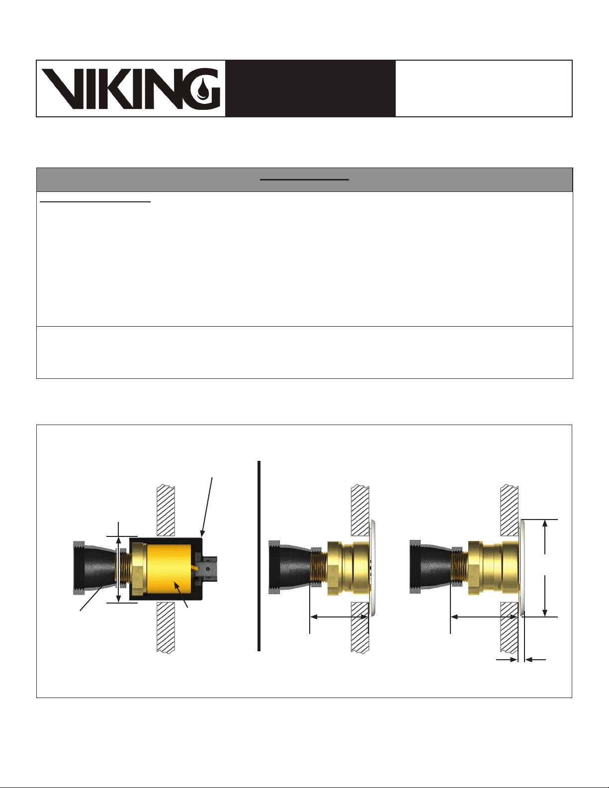
2-3/16” (56 mm)
diameter opening
required in the wall.
3/4”
(20 mm)
NPT
Concealed
sprinkler body
with protective
cap
Figure 4: Sprinkler VK680 Dimensions and Cover Installation
Form No. F_050611 18.10.25 Rev 17.1.P65
1-15/16”
(49 mm)
Minimum
1/4” (6 mm) Horizontal
adjustment available.
2-3/16”
(56 mm)
Maximum
Replaces Form No. F_050611 Rev 17.1
(Added P65 Warning.)
3-5/16”
(84 mm)
1/4”
(6 mm)
 Loading...