

Page 1
QUICK RESPONSE
ORDINARY HAZARD DRY
TECHNICAL DATA
The Viking Corporation, 210 N Industrial Park Drive, Hastings MI 49058
Telephone: 269-945-9501 Technical Services: 877-384-5464 Fax: 269-818-1680 Email: [email protected]
Visit the Viking website for the latest edition of this technical data page www.vikinggroupinc.com.
HSW FUSIBLE LINK
SPRINKLERS (8.0K)
(VK2843, VK2883, & VK2923)
1. DESCRIPTION
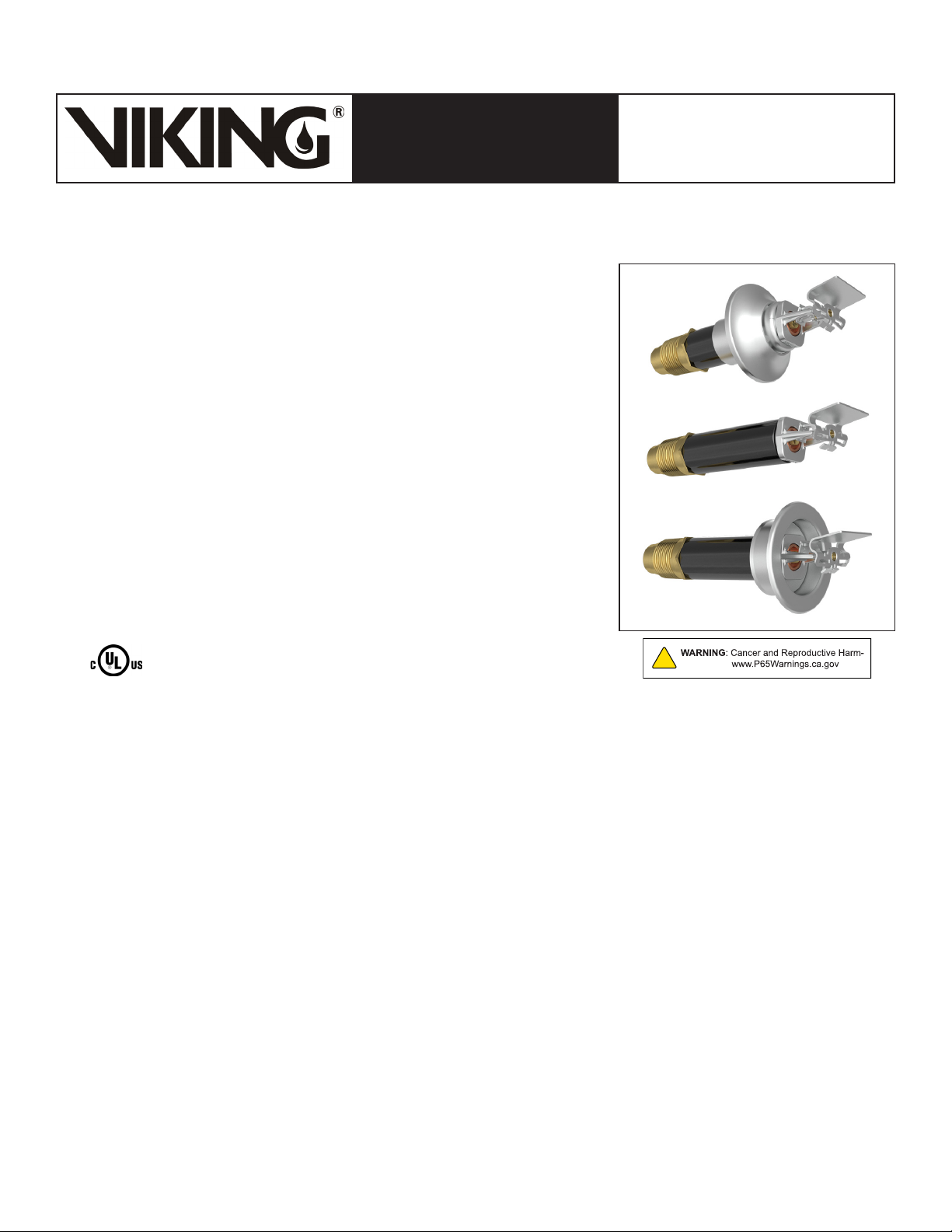
Viking Quick Response Ordinary Hazard Dry Horizontal Sidewall Sprinklers are
thermosensitive spray sprinklers suitable for use in areas subject to freezing.
The sprinklers are designed for dry systems and preaction systems where it is
necessary to prevent water or condensation from entering the drop nipple before
sprinkler operation. They may also be installed in spaces subject to freezing
and supplied from a wet system in an adjacent heated area. The large orifice
dry sidewall sprinkler allows greater flows at lower pressures than standard
orifice sprinklers. The newly desinged deflector carries an expanded approval for
installation from 4” to 12” below the ceiling.
Viking Quick Response Ordinary Hazard Dry Horizontal Sidewall Sprinklers
are available in various finishes and temperature ratings to meet design
requirements. The special Polyester coating has been investigated for installation
in corrosive atmospheres and is cULus listed as corrosion resistant as indicated
in the Approval Chart.
NOTE: When installed in some corrosive environments, the Polyester finish
may change color. This natural discoloration over time is not in itself an
indication of corrosion and should not be treated as such. All sprinklers
installed in corrosive environments should be replaced or tested as
described in NFPA 25 on a more frequent basis.
Page 1 of 8
2. LISTINGS AND APPROVALS
cULus Listed: Category VNIV
NYC Approved: MEA 89-92-E, Volume 37
Refer to the Approval Chart on page 3 and Design Criteria on page 4 for cULus Listing requirements that must be followed.
3. TECHNICAL DATA
Specications:
Available since 2005.
Minimum Operating Pressure: 7 PSI (0.5 bar)
Maximum Working Pressure: 175 PSI (12 bar).
Factory tested hydrostatically to 500 psi (34.5 bar)
Thread size: 1” NPT or 25 mm BSP
Nominal K-Factor: 8.0 U.S. (115.2 metric*) for lengths up to 48”.
* Metric K-factor measurement shown is when pressure is measured in bar. When pressure is measured in kPa, divide the metric K-factor shown by 10.0.
Covered by U.S. Patent numbers: 8,636,075 and 8,376,060
Material Standards:
Frame Casting: Brass UNS-C84400
Deflector: Phosphor Bronze UNS-C51000
Fusible Element Assembly: Nickel Alloy
Trigger and Support: Stainless Steel UNS-S31600
Belleville Spring Sealing Assembly: Nickel Alloy, coated on both sides with PTFE Tape
Compression Screw: Brass UNS-C36000
Seat and Adapter Assembly: Brass UNS-C36000
Orifice: Copper UNS-C11000 or UNS-C21000
Tube: ERW Hydraulic Steel Tube
Inlet and Barrel End: QM Brass or Brass UNS-C31400 or Brass UNS-C31600
Support (Internal): Brass UNS-C36000 or Brass UNS-C31400 or Brass UNS-C31600
Barrel: Steel Pipe UNS-G10260, Electrodeposited Epoxy Base finish
Sleeve (for Adjustable Standard style only): Brass UNS-C26000 or UNS-C26800
Form No. F_022717 18.11.01 Rev 18.1.P65
Replaces Form No. F_022717 Rev 18.1
(Added P65 Warning.)
Page 2
Page 2 of 8
QUICK RESPONSE
ORDINARY HAZARD DRY
TECHNICAL DATA
The Viking Corporation, 210 N Industrial Park Drive, Hastings MI 49058
Telephone: 269-945-9501 Technical Services: 877-384-5464 Fax: 269-818-1680 Email: [email protected]
Visit the Viking website for the latest edition of this technical data page www.vikinggroupinc.com.
HSW FUSIBLE LINK
SPRINKLERS (8.0K)
(VK2843, VK2883, & VK2923)
Escutcheon Materials:
Adjustable Standard Dry Escutcheons: Brass UNS-C26000 or UNS-C26800
Recessed Dry Escutcheons: Cold Rolled Steel UNS-G10080
Ordering Information: (Also refer to the current Viking price list.)
Order Quick Response Ordinary Hazard Dry Horizontal Sidewall Sprinklers by first adding the appropriate suffix for the sprinkler
finish, the appropriate suffix for the temperature rating, and then the suffix for the length (“A” dimension) to sprinkler base part
number. Order in a specific length noted as the “A” dimension (see Figures 3, 5, and 6). The “A” dimension is the distance from
the face of the fitting (tee) to the desired finished surface of the wall in which it is to be installed.
These sprinklers are listed and approved in lengths from 1-1/2” to 45-1/2” (38 mm to 1,156 mm) for the Adjustable Standard style,
3” to 47” (76 mm to 1,194 mm) for the Plain Barrel style, and 3-1/4” to 47-1/2” (83 mm to 1,207 mm) for the Adjustable Recessed
style.
Lengths exceeding the standard lengths are available, with no approvals, on a “made-to-order” basis: Recessed Dry Horizontal
Sidewall up to 64-1/2 (1,632 mm). Adjustable Standard Dry Horizontal Sidewall up to 62” (1,575 mm). Plain Barrel Dry Horizontal
Sidewall up to 64” (1,626 mm). Contact the manufacturer for more information.
Finish Suffix: Brass = A, Chrome = F, and White Polyester = M-/W
Temperature Suffix: 165 °F (74 °C)= C, 205 °F (96 °C) = E, 280 °F (138 °C) = G
For example, sprinkler VK2923 with 1” NPT Threads, Chrome finish, 165 °F (74 °C) temperature rating, and “A” length of 10” =
Part No. 21485FB10.
Available Finishes And Temperature Ratings: Refer to Table 1.
Accessories: (Also refer to the Viking website.)
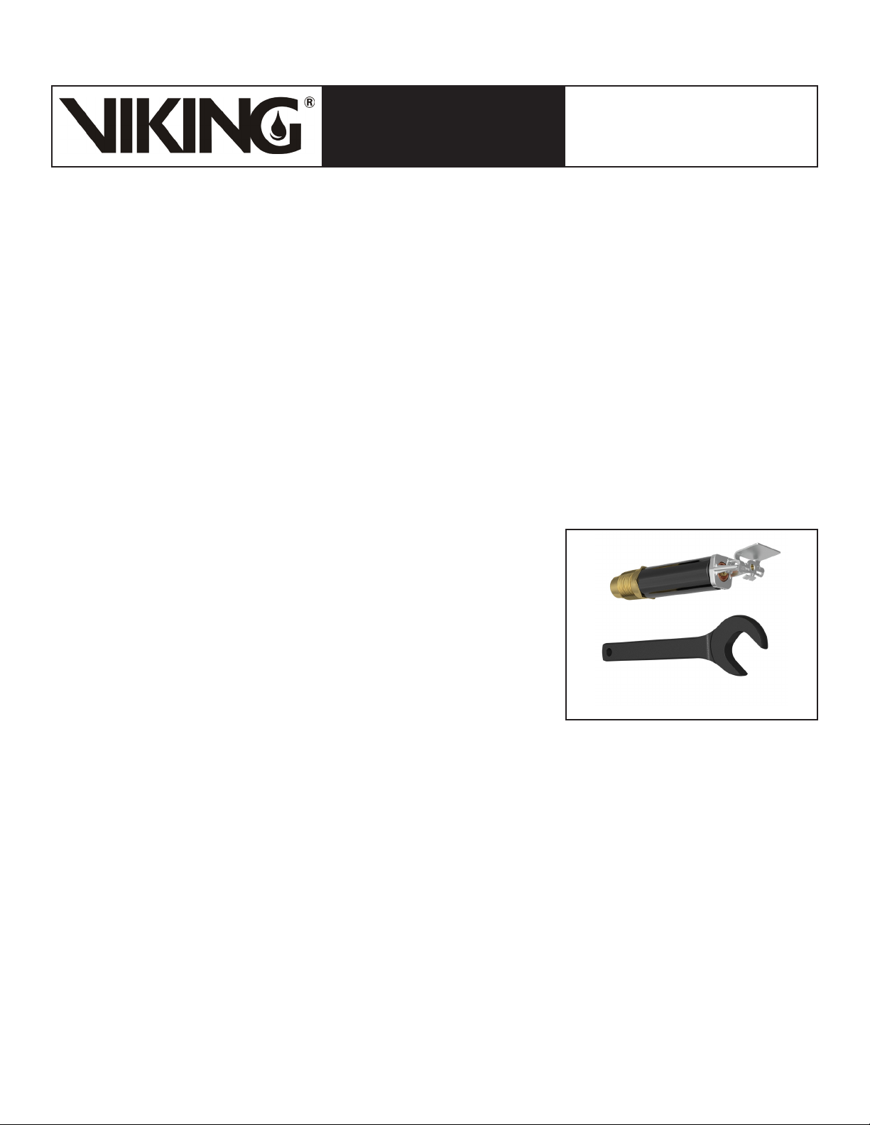
Sprinkler Wrenches:
A. Standard Wrench: Part No. 07297W/B (available since 1991)
B. Wrench for recessed sprinklers: Part No. 07565W/B** (available since 1991)
**A ½” ratchet is required (not available from Viking).
Dry Sprinkler Protective Cover: Part No. 15610
Replacement Escutcheons:
A. Adjustable Standard Dry Escutcheon: Base Part No. 08086F
B. Model E-1 Recessed Dry Escutcheon Cup: Base Part No. 05459A
4. INSTALLATION
Refer to appropriate NFPA Installation Standards.
Figure 1: Standard Sprinkler Wrench
07297W/B
5. OPERATION
During fire conditions, the heat-sensitive fusible element assembly disengages, releasing the internal parts to open the waterway.
Water flowing through the sprinkler orifice strikes the sprinkler deflector, forming a uniform spray pattern to extinguish or control
the fire.
6. INSPECTIONS, TESTS AND MAINTENANCE
Refer to NFPA 25 for Inspection, Testing and Maintenance requirements.
7. AVAILABILITY
The Viking Quick Response Ordinary Hazard Dry Horizontal Sidewall Sprinkler is available through a network of domestic and
international distributors. See The Viking Corporation web site for the closest distributor or contact The Viking Corporation.
8. GUARANTEE
For details of warranty, refer to Viking’s current list price schedule or contact Viking directly.
Form No. F_022717 18.11.01 Rev 18.1.P65
Page 3
Page 3 of 8
QUICK RESPONSE
ORDINARY HAZARD DRY
TECHNICAL DATA
The Viking Corporation, 210 N Industrial Park Drive, Hastings MI 49058
Telephone: 269-945-9501 Technical Services: 877-384-5464 Fax: 269-818-1680 Email: [email protected]
Visit the Viking website for the latest edition of this technical data page www.vikinggroupinc.com.
TABLE 1: AVAILABLE SPRINKLER TEMPERATURE RATINGS AND FINISHES
HSW FUSIBLE LINK
SPRINKLERS (8.0K)
(VK2843, VK2883, & VK2923)
Sprinkler Temperature
Classification
Sprinkler Nominal
Temperature Rating
1
Ceiling Temperature
2
Maximum Ambient
Frame Paint
2
Color
Ordinary 165 °F (74 °C) 100 °F (38 °C) None
Intermediate 205 °F (96 °C) 150 °F (65 °C) White
High 280 °F (138 °C) 225 °F (107 °C) Blue
Sprinkler Finishes: Brass, Chrome, and White Polyester
Footnotes
1
The sprinkler temperature rating is stamped on the deflector.
2
Based on NFPA-13. Other limits may apply, depending on fire loading, sprinkler location, and other requirements of the Authority Having Jurisdiction.
Refer to specific installation standards.
Approval Chart
Quick Response Ordinary Hazard Dry
HSW Fusible Link Sprinklers (8.0K)
Maximum 175 PSI (12 bar) WWP
Sprinkler
Base Part
Number
21491U VK2883
21492U VK2883 -- 25 mm 1/2” 12.7 A1 -- A1 -- -- -- --
21485U VK2923
21486U VK2923 -- 25 mm 1/4” 6.35 B2 -- B2 -- -- -- --
21497U VK2843
21498U VK2843 -- 25 mm 1/2” 12.7 A3 -- A3 -- -- -- --
SIN Style
1
Adjustable
Standard
Adjustable
Recessed
Plain Barrel
Thread Size
NPT BSP Inches mm cULus5FM NYC6VdS LPCB
Nominal
K-Factor
2
1” --
1” -- 1/4” 6.35 B2 -- B2 -- -- -- --
8.0 U.S.
(115.2 metric3)
1” -- 1/2” 12.7 A3 -- A3 -- -- -- --
Order Length
Increment
1/2” 12.7 A1 -- A1 -- -- -- --
Listings and Approvals
(Refer also to Design Criteria on page 4.)
4
Approved Temperature Ratings
A - 165 °F (74 °C), 205 °F (96 °C), and 280 °F (138
°C)
B - 165 °F (74 °C) and 205 °F (96 °C)
1
Part number shown is the base part number. For complete part number, refer to current Viking price list schedule.
2
K-Factor applies for standard lengths (“A” Dimensions indicated above).
3
Metric K-factor shown is for use when pressure is measured in bar. When pressure is measured in kPa, divide the metric K-factor shown by 10.0.
4
This chart shows the listings and approvals available at the time of printing. Other approvals may be in process. Check with the manufacturer for any
additional approvals.
5
Listed by Underwriter’s Laboratories for use in the U.S. and Canada.
6
Accepted for use, City of New York Department of Buildings, MEA 89-92-E, Vol. 37.
1 - Chrome or White Polyester sprinkler with a Chrome or White Polyester Sleeve and Escutcheon
with “A” dimensions 1-1/2” to 45-1/2” (38.1 mm to 1,156 mm)
2 - Chrome or White Polyester with “A” dimensions 3-1/4” to 47-1/2” (82.5 mm to 1,207 mm)
3 - Chrome or Brass with “A” dimensions 3” to 47” (76.2 mm to 1,194 mm)
Footnotes
Approved Finishes and “A” Dimensions
Form No. F_022717 18.11.01 Rev 18.1.P65
Page 4
Page 4 of 8
QUICK RESPONSE
ORDINARY HAZARD DRY
TECHNICAL DATA
The Viking Corporation, 210 N Industrial Park Drive, Hastings MI 49058
Telephone: 269-945-9501 Technical Services: 877-384-5464 Fax: 269-818-1680 Email: [email protected]
Visit the Viking website for the latest edition of this technical data page www.vikinggroupinc.com.
HSW FUSIBLE LINK
SPRINKLERS (8.0K)
(VK2843, VK2883, & VK2923)
(Also refer to the Approval Chart on page 3.)
DESIGN CRITERIA
NOTE: When using CPVC fittings with Viking dry sprinklers, use only new Nibco Model 5012-S-Bl tees. When selecting other CPVC fittings,
contact Viking Technical Services.
cULus Listing Requirements:
Quick Response Dry Horizontal Sidewall Fusible Link Sprinklers are cULus Listed as indicated in the Approval Chart for installation in accordance with
the latest edition of NFPA 13 for standard spray sprinklers.
• Designed for use in Light and Ordinary Hazard occupancies with smooth, flat ceilings only.
• Protection areas and maximum spacing shall be in accordance with the tables provided in NFPA 13.
• Minimum spacing allowed is 6 ft. (1.8 m).
• Deflector must be positioned between 4” and 12” (102 mm and 305 mm) below the ceiling. Keep the top of the deflector oriented parallel with the
ceiling.
• Locate no less than 4” (102 mm) from end walls.
• Maximum distance from end walls shall be no more than one-half of the allowable distance between sprinklers. The distance shall be measured
perpendicular to the wall.
• The sprinkler installation and obstruction rules contained in NFPA 13 for sidewall standard spray sprinklers must be followed.
IIMPORTANT: Always refer to Bulletin Form No. F_091699 - Care and Handling of Sprinklers. Also refer to Form No. F_080614
for general care, installation, and maintenance information. Viking sprinklers are to be installed in accordance with the latest
edition of Viking technical data, the appropriate standards of NFPA, FM Global, LPCB, APSAD, VdS or other similar organizations, and also with the provisions of governmental codes, ordinances, and standards, whenever applicable.
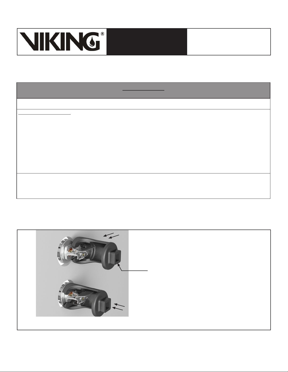
Figure 2: Wrench 07565W/B for Adjustable Recessed Dry Horizontal Sidewall Sprinklers
** NOTE: A 1/2” ratchet is required and not available from Viking.
Form No. F_022717 18.11.01 Rev 18.1.P65
Step 1:
Carefully slide the wrench sideways around
the deector and fusible link as shown.
Sprinkler Wrench
(Part No. 07565W/B)** for installing recessed dry sprinklers.
Step 2:
Press the wrench onto the sprinkler wrench
ats and turn slightly to ensure engagement
with the wrench ats.
Page 5
Page 5 of 8
QUICK RESPONSE
ORDINARY HAZARD DRY
TECHNICAL DATA
The Viking Corporation, 210 N Industrial Park Drive, Hastings MI 49058
Telephone: 269-945-9501 Technical Services: 877-384-5464 Fax: 269-818-1680 Email: [email protected]
Visit the Viking website for the latest edition of this technical data page www.vikinggroupinc.com.
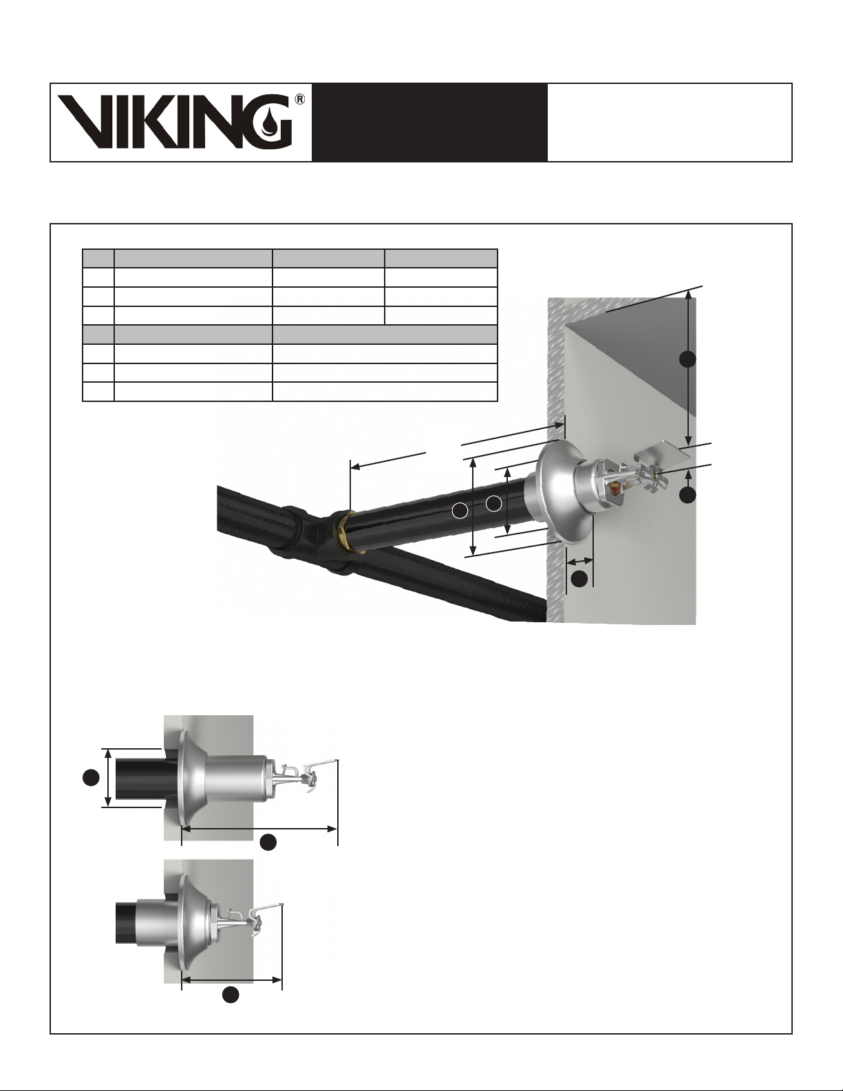
Ref Variable Parameter Minimum Maximum
1 Wall opening 1-3/4” (45 mm) 2-1/4” (57 mm)
2 Deflector to ceiling distance 4” (102 mm) 12” (305 mm)
3 Deflector to wall distance 3-1/4” (83 mm) 5-1/4” (113 mm)
Ref Fixed Parameter Value
4 Escutcheon depth 13/16” (21 mm)
5 Escutcheon outer diameter 3-1/16” (78 mm)
6 Top of deflector to centerline 5/8” (16 mm)
Finished Wall
HSW FUSIBLE LINK
SPRINKLERS (8.0K)
(VK2843, VK2883, & VK2923)
Finished Ceiling
2
A
1
5
6
4
Determining the “A” Dimension: Adjustable Standard HSW Sprinkler
1. Determine the distance from the face of the tee to the nished face of the wall.
2. Round to the nearest 1/2” (13mm) between 1-1/2” (38 MM) and 45-1/2” (1,156 mm).
NOTE: The deector will extend approximately 4-1/4” (108 mm) from the wall with 2” +/- 1” (25 mm) horizontal adjustment available.
To locate the deector at the maximum distance
1
from the wall, with no adjustment available, order the
standard dry horizontal sidewall sprinikler 1” (25 mm)
longer than the “A” Dimension.
3
To locate the deector at the minimum distance
from the wall, with no adjustment available, order the
standard dry horizontal sidewall sprinikler 1” (25 mm)
shorter than the “A” Dimension.
3
Figure 3: Adjustable Standard Ordinary Hazard Dry HSW Sprinkler
Form No. F_022717 18.11.01 Rev 18.1.P65
Page 6
QUICK RESPONSE
ORDINARY HAZARD DRY
TECHNICAL DATA
HSW FUSIBLE LINK
SPRINKLERS (8.0K)
(VK2843, VK2883, & VK2923)
The Viking Corporation, 210 N Industrial Park Drive, Hastings MI 49058
Telephone: 269-945-9501 Technical Services: 877-384-5464 Fax: 269-818-1680 Email: [email protected]
Visit the Viking website for the latest edition of this technical data page www.vikinggroupinc.com.
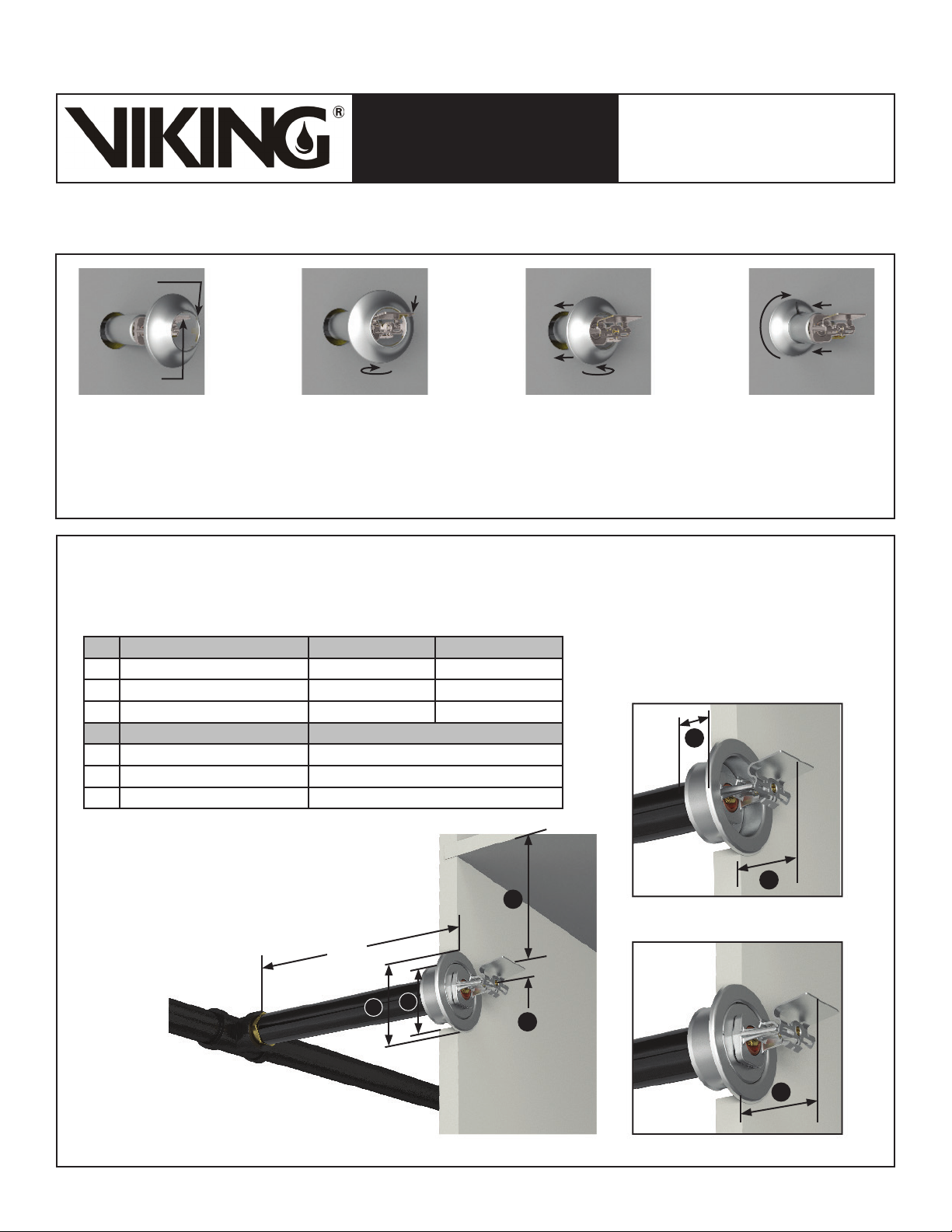
SLOT
DEFLECTOR
Page 6 of 8
Step 1: Align the slot in the
escutcheon with the horizontal
surface of the deector as shown.
Step 2: Push the rounded end
of the slot against the near edge
of the deector.Slighty rotate the
escutcheon horizontally and push
the far side of the escutcheon past
the deector, toward the sleeve.
Step 3: Re-align the escutcheon
with the sprinkler barrel and
continue pushing it toward the
sleeve.
Step 4: Push and rotate the
escutcheon onto the sleeve
and, if desired, orient the slot
toward the top to minimize
visibility.
Figure 4: Adjustable Standard Escutcheon Installation
Determining the “A” Dimension: Adustable Recessed HSW Sprinkler with Model E-1 Escutcheon
1. Determine the distance from the face of the tee to the nished face of the wall.
2. Round to the nearest 1/4” (16 mm) between 3-1/4” (83 mm) and 47-1/2” (1,207 mm).
NOTE: The sprinkler will be recessed approximately 5/16” (8 mm) with 5/8” (16 mm) horizontal adjustment available.
Ref Variable Parameter Minimum Maximum
1 Wall opening 2-1/8” (54 mm) 2-1/2” (64 mm)
2 Deflector to ceiling distance 4” (102 mm) 12” (305 mm)
3 Deflector to wall distance 1-7/8” (48 mm) 2-1/2” (64 mm)
Ref Fixed Parameter Value
4 Escutcheon depth (Model E-1) 1-1/16” (27 mm)
5 Escutcheon outer diameter 3-1/16” (78 mm)
6 Top of deflector to centerline 5/8” (16 mm)
4
Finished
Ceiling
2
A
1
5
Figure 5: Adjustable Recessed Ordinary Hazard Dry HSW Fusible Link Sprinkler with the Model E-1 Escutcheon
Form No. F_022717 18.11.01 Rev 18.1.P65
6
Finished Wall
3
3
Page 7
QUICK RESPONSE
ORDINARY HAZARD DRY
TECHNICAL DATA
The Viking Corporation, 210 N Industrial Park Drive, Hastings MI 49058
Telephone: 269-945-9501 Technical Services: 877-384-5464 Fax: 269-818-1680 Email: [email protected]
Visit the Viking website for the latest edition of this technical data page www.vikinggroupinc.com.
HSW FUSIBLE LINK
SPRINKLERS (8.0K)
(VK2843, VK2883, & VK2923)
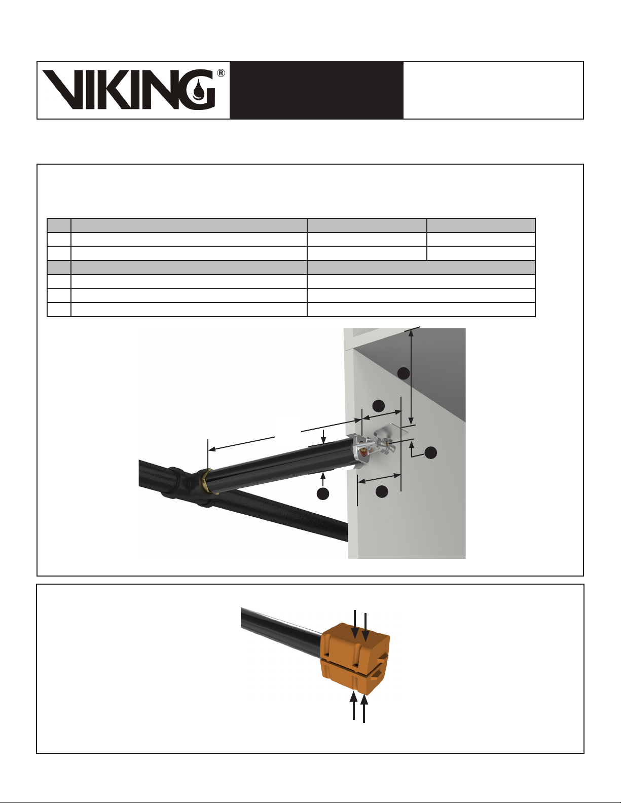
Determining the “A” Dimension - Plain Barrel Dry HSW Sprinkler
1. Determine the distance from the face of the tee to the base of the sprinkler.
2. Round to the next higher 1/2” (13 mm) increment, between 3” (76 mm) and 47” (1,194 mm).
Ref Variable Parameter Minimum Maximum
1 Deflector to ceiling distance 4” (102 mm) 12” (305 mm)
2 Deflector to finished wall distance Do not recess wrench boss 6” (152 mm)
Ref Fixed Parameter Value
3 Sprinkler base to deflector distance 2-1/4” (57 mm)
4 Top of deflector to centerline 5/8” (16 mm)
5 Pipe outside diameter (Same as 1” (13 mm) Schedule 40 pipe) 1-5/16” (33 mm)
Page 7 of 8
Figure 6: Plain Barrel Quick Response Dry Ordinary Hazard HSW Fusible Link Sprinkler
Shown with an Plain Barrel Dry HSW
Sprinkler. The protective cover may also
be used with the Adjustable Recessed or
Adjustable Standard style Dry HSW Sprinkler.
A
1
3
5
2
Finished
Press the cover together
until it snaps closed.
Finished
Ceiling
4
Wall
NOTE: Remove the sprinkler clip and cover
before placing the system in service!
Figure 7: Dry Horizontal Sidewall Sprinkler Cover Part Number 15610 (shown with a Plain Barrel Dry HSW FL Sprinkler)
(Optional for temporary use with Viking Dry HSW Sprinklers until finish work is completed around the sprinkler.)
Form No. F_022717 18.11.01 Rev 18.1.P65
Page 8
Page 8 of 8
QUICK RESPONSE
ORDINARY HAZARD DRY
TECHNICAL DATA
The Viking Corporation, 210 N Industrial Park Drive, Hastings MI 49058
Telephone: 269-945-9501 Technical Services: 877-384-5464 Fax: 269-818-1680 Email: [email protected]
Visit the Viking website for the latest edition of this technical data page www.vikinggroupinc.com.
HSW FUSIBLE LINK
SPRINKLERS (8.0K)
(VK2843, VK2883, & VK2923)
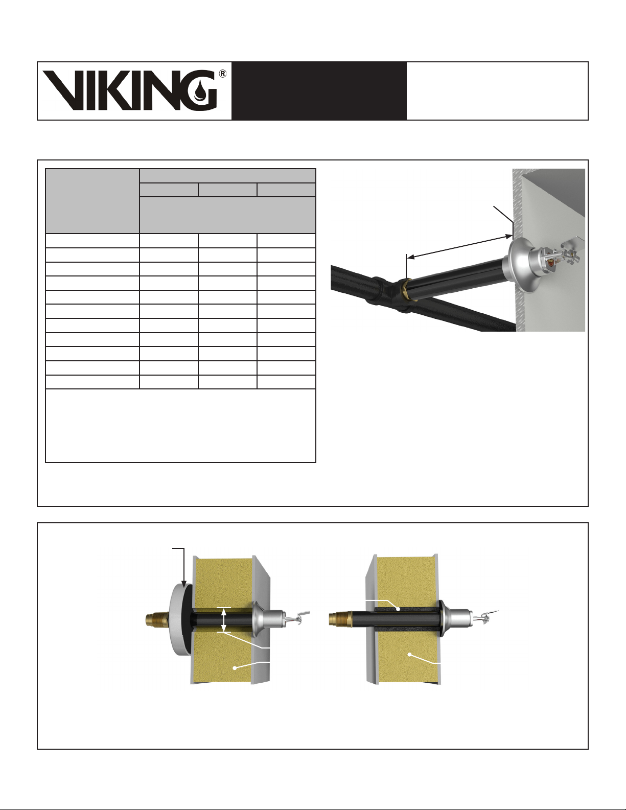
Ambient Temperature
of the Protected Area*
at the Discharge End
of the Sprinkler
40 °F (4 °C) 0 0 0
30 °F (-1 °C) 0 0 0
20 °F (-7 °C) 4 (100) 0 0
10 °F (-12 °C) 8 (203) 1 (25) 0
0 °F (-18 °C) 12 (305) 3 (76) 0
-10 °F (-23 °C) 14 (356) 4 (102) 1 (25)
-20 °F (-29 °C) 14 (356) 6 (152) 3 (76)
-30 °F (-34 °C) 16 (406) 8 (203) 4 (102)
-40 °F (-40 °C) 18 (457) 8 (203) 4 (102)
-50 °F (-46 °C) 20 (508) 10 (254) 6 (152)
-60 °F (-51 °C) 20 (508) 10 (254) 6 (152)
* The protected area refers to the area below the ceiling, the ambient
temperature is the temperature at the discharge end of the sprinkler.
For protected area temperatures that occur between the values
listed, use the next cooler temperature.
** The minimum reuired barrel length is not the same as the “A”
dimension. Refer to Figures 3, 5, and 6 for the “A” Dimension.
Exposed minimum barrel lengths aer inclusive up to 30 mph wind
velocities.
Exposed Barrel Ambient Temperature
40 °F (4 °C) 50 °F (10 °C) 60 °F (16 °C)
Exposed Minimum Barrel Length**
Face of the Tee to the Outer Surface of the Wall
Inches (mm) Inches (mm) Inches (mm)
Outer surface of wall
Exposed Barrel
Seal the clearance space around the sprinkler to avoid leakage of
air into the protected area and consequent formation of condensate
around the sprinkler frame, which could inhibit operation or cause
premature operation. Refer to Figure 9.
If humidity and temperature differential causes condesation on the
exposed dry sprinkler barrel, consider wrapping the exposed barrel
with insualtion, foam insulating tape, or equivalent.
Install the threaded end of the sprinker into a 1” NPT outlet of a
malleable iron tee fitting per ANSI B 16.3 (Class 150)
or cast iron threaded tee fitting per ANSI 16.4 (Class 125) only.
Figure 8: Dry Horizontal Sidewall Sprinkler Minimum Barrel Length Based on Ambient Temperature in the Protected Area
(Adjustable Standard Dry HSW Sprinkler is Shown)
Seal Part Number
19398M/W or
equivalent method.
Seal
Clearance Opening
Insulated wall Insulated wall
Dry sprinkler seal on the exterior of the wall Dry sprinkler seal within the wall
Figure 9: Dry Sprinkler Seal (Adjustable Standard Dry HSW Sprinkler is Shown)
Form No. F_022717 18.11.01 Rev 18.1.P65
Replaces Form No. F_022717 Rev 18.1
(Added P65 Warning.)
 Loading...