

Page 1
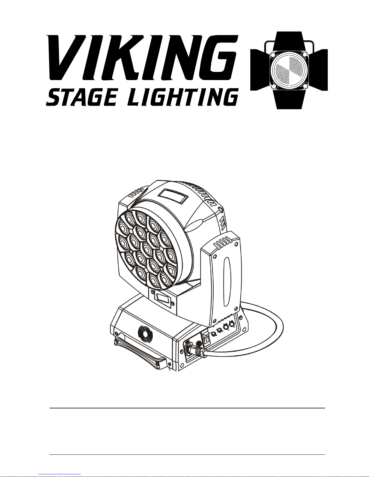
VK10 VORTEX MOVING HEAD
USER MANUAL
Rev 2.01
Page 2
CAUTION ! EYE DAMAGE !
Avoid looking directly into the light source!
This device has left our premises in absolutely perfect condition. In order to maintain this condition & to
ensure a safe operation, it is absolutely necessary for the user to follow the safety instructions and warning
notes written in this manual.
The manufacturer will not accept liability for any resulting damages caused by the non-observance of this
manual or any unauthorized modification to the device.
Please consider that damages caused by manual modifications to the device are not subject to warranty.
1. Safety instructions
Make sure that the available voltage is not higher than stated on the rear panel of the fixture.
This fixture should be operated only from the type of power source indicated on the label. If you are not
sure of the type of power supplied, consult your authorized distributor or local power company.
Always disconnect the fixture from AC power before cleaning, removing or installing the fuses, or any part.
The power plug has to be accessible after installing the fixture. Do not overload wall outlets and extension cords
as this can result in fire or electric shock.
Do not allow anything to rest on the power cord. Do not locate this fixture where the cord may be damaged by
persons walking on it.
Make sure that the power cord is never crimped or damaged by sharp edges. Check the fixture and the power
cord from time to time.
Refer servicing to qualified service personnel.
Do not connect this fixture to a dimmer pack.
During the initial start-up some smoke or smell may arise. This is a normal process and does not necessarily
mean that the device is defective.
Do not touch the device’s housing with bare hands during its operation (housing becomes
hot)!
For replacement use lamps and fuses of same type and rating only.
FOR YOUR OWN SAFETY, PLEASE READ THIS USER MANUAL CAREFULLY
BEFORE YOU INITALLY START
This light was designed for indoor use and it is intended for
professional application only. It is not for household use.
CAUTION!
Disconnect the fixture from mains before you remove any cover of the fixture.
With a high voltage you can suffer a dangerous electric shock when touching
live wires and electrical parts under covers!
This fixture falls under protection class I. Therefore this fixture has to be connected to
a mains socket outlet with a protective earthing connection.
Page 3
If the fixture has been exposed to drastic temperature fluctuation (e.g. after transportation), do not switch it on
immediately. The arising condensation water might damage your device. Leave the device switched off until
it has reached room temperature.
Do not shake the fixture. Avoid brute force when installing or operating the fixture.
This fixture was designed for indoor use only; do not expose this unit to rain or use near water.
When choosing the installation spot, please make sure that the fixture is not exposed to extreme heat, moisture
or dust.
Air vents and slots in the fixture´s head and base are provided for ventilation, to ensure reliable operation of
the device and to protect it from overheating.
Do not block the front objective lens with any object when the fixture is under operation.
The openings should never be covered with cloth or other materials, and never must be blocked.
The fixture becomes very hot during operation. Allow the fixture to cool approximately 5 minutes prior to
examination.
This fixture should not be placed in a built-in installation unless proper ventilation is provided.
Only operate the fixture after having checked that the housing is firmly closed and all screws are tightly
fastened.
Always use a secondary safety cable when mounting this fixture.
Make sure that the area below the installation place is blocked when rigging, derigging or servicing the
fixture.
The maximum ambient temperature 45°C must never be exceeded.
Operate the device only after having familiarized with its functions. Do not permit operation by persons not
qualified for operating the device. Most damages are the result of unprofessional operation!
Please keep the original packaging if the device is to be transported or returned to the deal for service or repair.
Warning
The minimum distance between light output and the illuminated surface must be more
than 0.5 meters.
CAUTION!
The lens has to be replaced when it is obviously damaged,
so its function is not impaired, e. g. due to cracks or deep scratches!
CAUTION!
Fast on-off-cycles (e.g. constant switching on/off) can damage the unit.
Page 4
2. Installation
2.1 Connection to the mains
The VK10 VORTEX is equipped with auto-switching power supply that automatically adjusts to any 5060Hz AC power source from 100-240 Volts.
This fixture must be earthed. To use the fixture, a plug must be fixed.
The correct assembly of a sufficient plug may be done by professional persons only.
The conductors in the cable are marked by the following table.
Core (EU) Core (US) Connection Plug Terminal Marking
Brown
Light blue
Green /Yellow
Black
White
Green
Live
Neutral
Earth
L
N
2.2 Rigging the fixture
A structure intended for installation of the fixture (s) must safely hold weight of the fixture(s) placed on it. The
structure has to be certificated to the purpose.
The fixture (fixtures) must be installed in accordance with national and local electrical and construction codes
and regulation.
When rigging, derigging or servicing the fixture staying in the area below the installation place, on bridges,
under high working places and other endangered areas is forbidden.
The operator has to make sure that safety-relating and machine-technical installations are approved by an expert
before taking into operation for the first time and after changes before taking into operation another time.
The operator has to make sure that safety-relating and machine-technical installations are approved by a skilled
person once a year.
Allow the fixture to cool for ten minutes before handling.
The projector should be installed outside areas where persons may walk by or be seated.
IMPORTANT! OVERHEAD RIGGING REQUIRES EXTENSIVE EXPERIENCE, including calculating working
load limits, installation material being used, and periodic safety inspection of all installation material and the
projector. If you lack these qualifications, do not attempt the installation yourself, but use a help of professional
companies.
CAUTION: Fixtures may cause severe injuries when crashing down! If you have doubts concerning the safety
of a possible installation, do not install the fixture!
Fixtures must be installed by a qualified electrician in accordance with all
national and local electrical and construction codes and regulations.
For protection from electric shock, the fixture must be earthed!
For overhead installation, the fixture must be always secured with a safety wire
Page 5
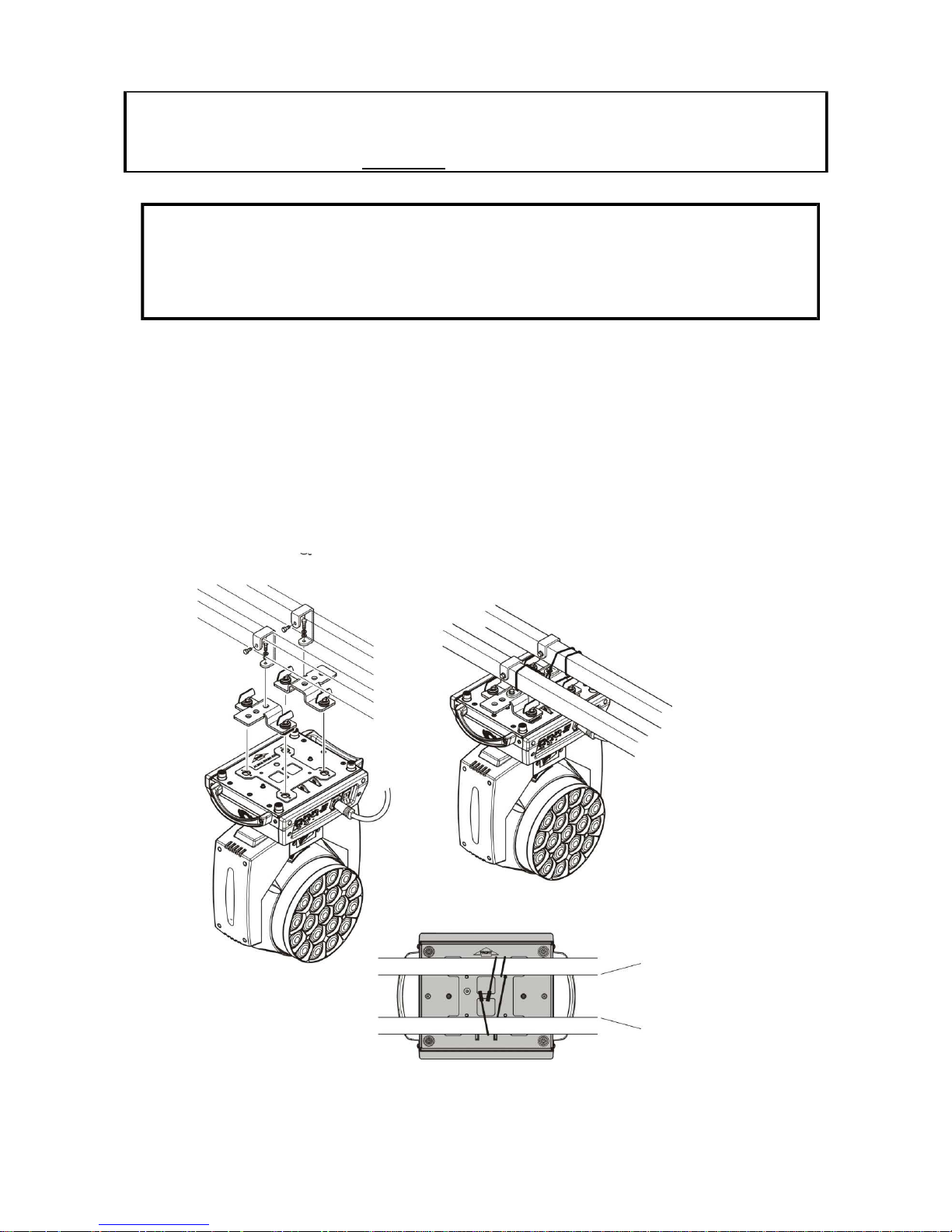
The fixture has to be installed out of the reach of the prying fingers of the public.
The fixture can be placed directly on the stage floor or rigged in any orientation on a truss without altering its
operation characteristics.
For securing a fixture to the truss, install a safety wire that can hold at least 10 times the weight of the fixture.
Use only the safety wire with screw-on carabineer. Pull the safety wire through the safety attachment point
on the bottom of the base and around the truss as shown on the pictures below.
Truss installation
1. Bolt each hook clamp to the omega holder with M10 bolt and lock nut through the hole in the holder.
2. Fasten the omega holders on the bottom of the base by inserting both quick-lock fasteners into the holes of
the base and tighten fully clockwise.
3. Pull the safety bond wire through the attachment point and around the truss as indicated below
Alternatively, fixtures handles can be used stood vertically on the floor or solid surface
Danger of fire !
When installing the device, make sure there is no highly inflammable
material (decoration articles, etc.) in a distance of min. 1 m.
CAUTION!
Use 2 appropriate clamps to rig the fixture on the truss.
Follow the instructions mentioned at the bottom of the base.
Make sure that the device is fixed properly! Ensure that the
structure (truss) to which you are attaching the fixtures is secure.
Page 6
Power supply connection
The equipment can be used on a wide voltage input from 100 to 240v AC. Please make sure the
voltage is in this scale when connecting the power.
Mains input is via industry standard Powercon (Blue) Connectors. You can daisy chain a maximum
of 6 units using Powercon link cables (Blue & white connectors) for ease of rigging.
This unit’s mains supply must NOT be connected to a Dimmer
The unit is externally fused with a 3.15a 20mm ceramic fuse located on the Input/Output panel and
must be replaced with the same rating in the case of failure.
DMX Signal Connection
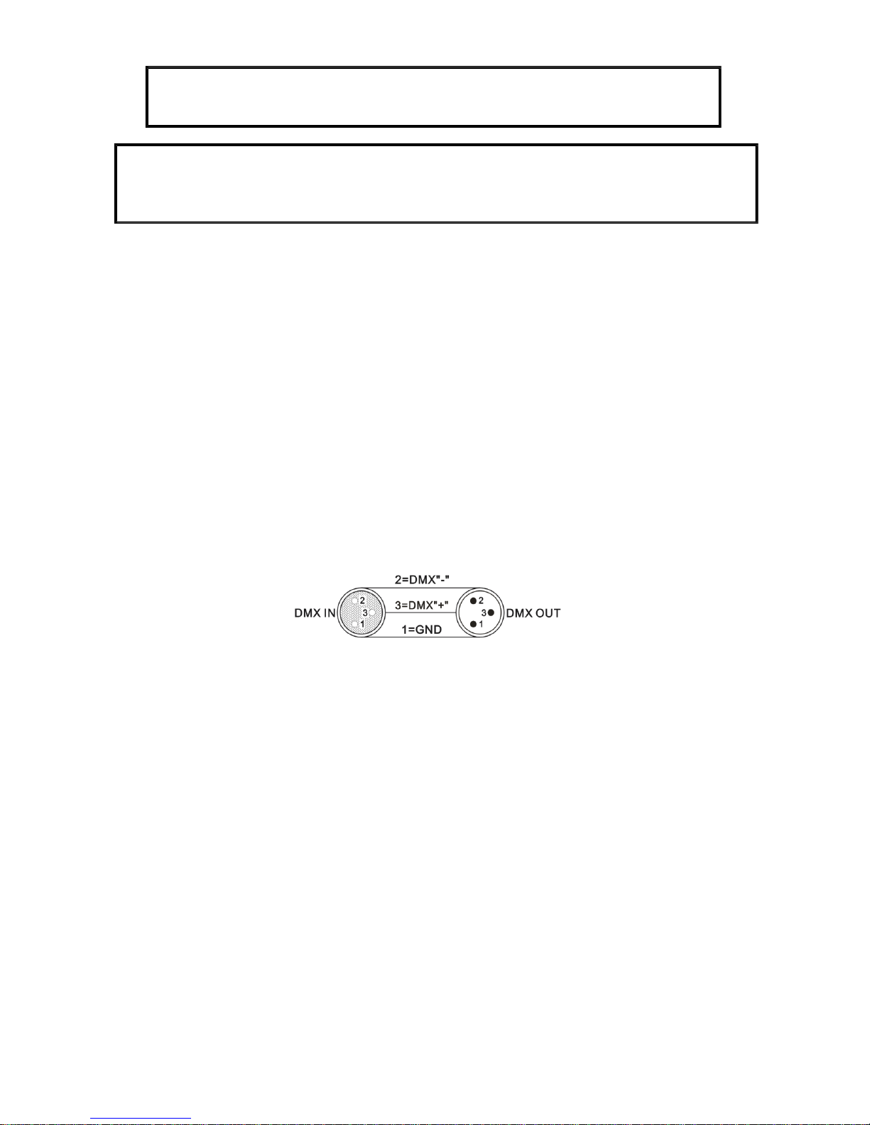
1. Use standard 3 pin DMX cable to plug into the 1st light (male) and daisy chain further lights as
Required. The DMX signal conforms to industry standard protocol as per the picture below;
.
2. Although not always necessary we would always recommend the use of a DMX signal
Terminator on the last light in the chain to prevent stray signals causing interference. This is
particularly important on a long run of DMX.
3.
A DMX terminator can be made by soldering a 120Ω resistor between DMX- (pin2) & DMX+
(pin3) of a 3 pin XLR male Connector
When installing fixtures side-by-side,
avoid illuminating one fixture with another!
DANGER TO LIFE!
Before taking into operation for the first time, the installation has to be approved by
an expert!
Page 7
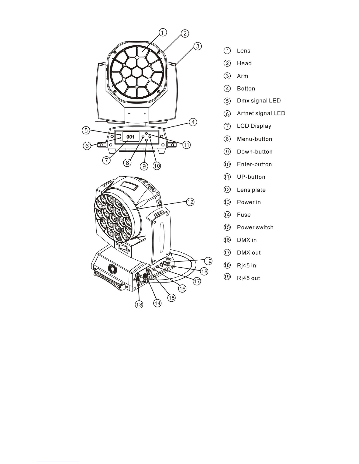
VK10 VORTEX Product Overview
VK10 VORTEX Specification
● XLR sockets input/output 3Pin
● Power input/output on Powercon 10a Connector
● 4 kinds of control model: DMX512, Artnet ,Sound Activated, Master/slave
● LCD display screen
● Display screen can be turned upside down 180°to fit the installation in different places
● Indoor operation only :Temperature:-20°C~+40°C
● 5 DMX modes:21 / 35 / 78 / 92 / 96 Channels
● Dimmer 0-100% linear dimmer
● Pan/tilt:
16bit fine pan/tilt control
Smooth and accurate locating
Pan:540° Tilt:210°
Motor rotation in forward and reverse
● Each LED can be controlled individually and has rich colour
● The front lens has infinite rotation in both forward and reverse
● Strobe from 0 to 20HZ
● Zoom Lens with range :4°-60°
● Rated Voltage: AC100V~240V 50-60HZ
Page 8
● Rated Power: 450W
● LED Qty: 19x15W high power 4 in 1 LEDs
● LED Drive Current: 1000mA
● IP Rating: IP20 Indoor or sheltered from Rain Only
● DMX Mode: 21CH(Standard)/ 35CH(Shapes) / 78CH(Extend)
/96CH (Extend RGBW) /92CH (Full)
● Net weight: 15 Kg
● Super mixed colour and rainbow effect.
● 7 programmable custom programs which can be invoked by the DMX controller.
● Fan cooling (fan will change speed with the temperature variation
VK10 VORTEX Operation
The Main principle of controlling and setting the light on the LCD display is with the aid of the 4
buttons for navigation;
Button Function
MENU Choose Menu or function exit
ENTER Current show menu or enter into the current selected function
UP Increase the value
DOWN Decrease the value
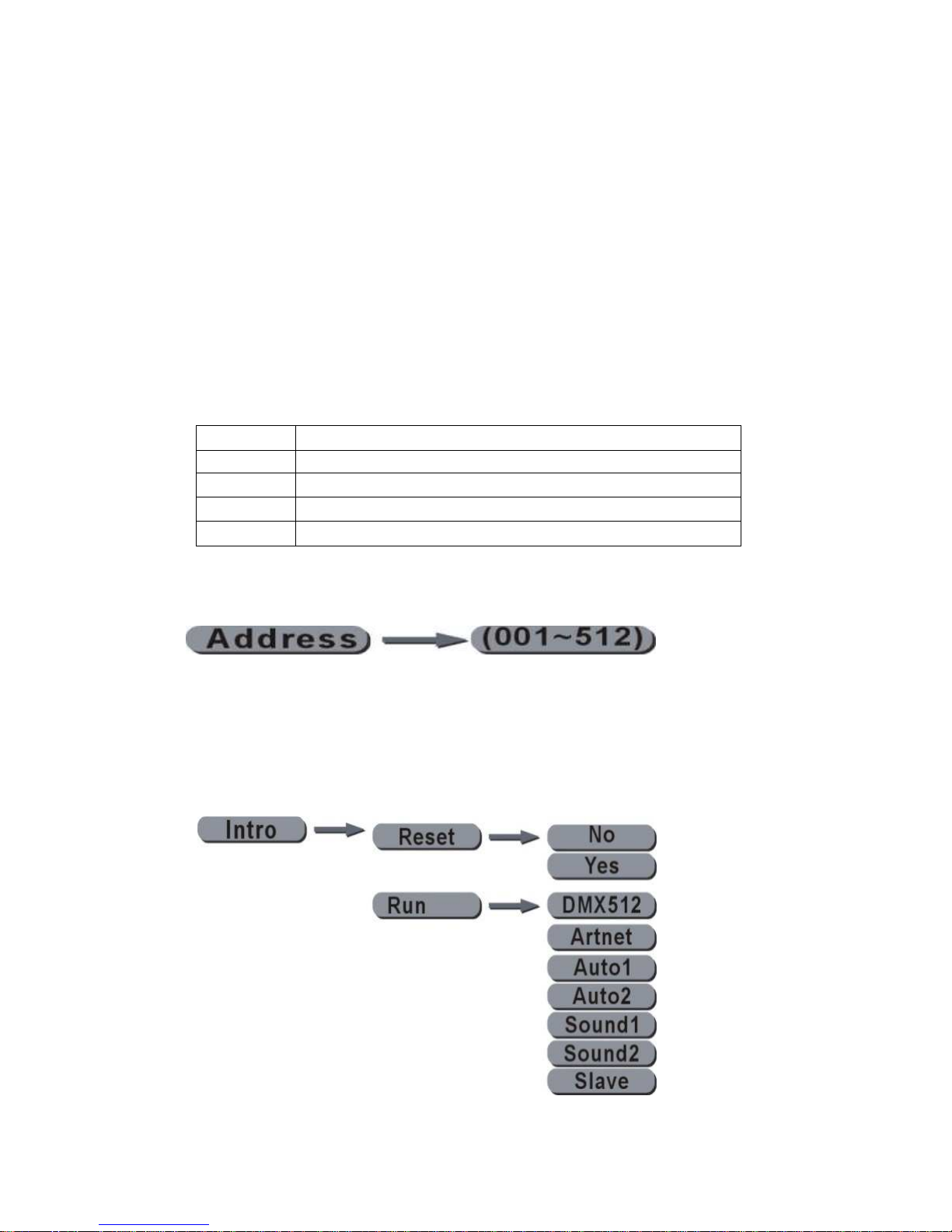
1) DMX Address setting:
● Press MENU until it shows 【Address】,then press ENTER.
● Change the DMX address with the UP or DOWN buttons and then press ENTER to accept.
2) Function selection
● Press MENU until it shows 【Intro
】
, then press ENTER
● Press UP or DOWN to select either 【Reset】、or【 Run】.
● To reset the unit to factory defaults choose Reset & press ENTER, then press UP or DOWN to
select【YES】& press ENTER to reset to factory settings
Page 9
● When choosing Run, press ENTER & there are 7 options selected using the UP / DOWN cursor
buttons as before;
DMX512 Select for DMX 512 Via 3 pin XLR (DMX LED will flash if DMX is present)
Artnet Select for ARTNET Via RJ45 (Artnet LED will flash if Artnet is present)
Auto1 Select Auto1 program – this unit becomes the Master in Master/slave setups
Auto2 Select Auto2 program – this unit becomes the Master in Master/slave setups
Sound1 Select Sound1 program – this unit becomes the Master in Master/slave setups
Sound2 Select Sound2 program – this unit becomes the Master in Master/slave setups
Slave Select Slave & quit to main menu so light is set as Slave
。
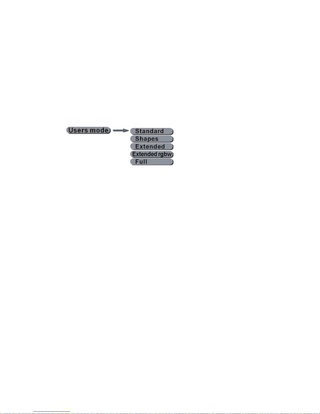
3) DMX User Mode selection
Select the user mode (number of DMX Control Channels) by using the cursor UP/DOWN buttons as
before to select the appropriate user mode type as listed below;
Standard 21 DMX Channels: Basic Control
Shapes 35 DMX Channels: Allows creation of shapes
Extended 78 DMX Channels: allows individual RGB LED Control
Extended RGBW 96 DMX Channels: allows full RGBW individual LED Control
Full 92 DMX Channels: allows RGBW shapes, RGB, & Patten Control
Page 10
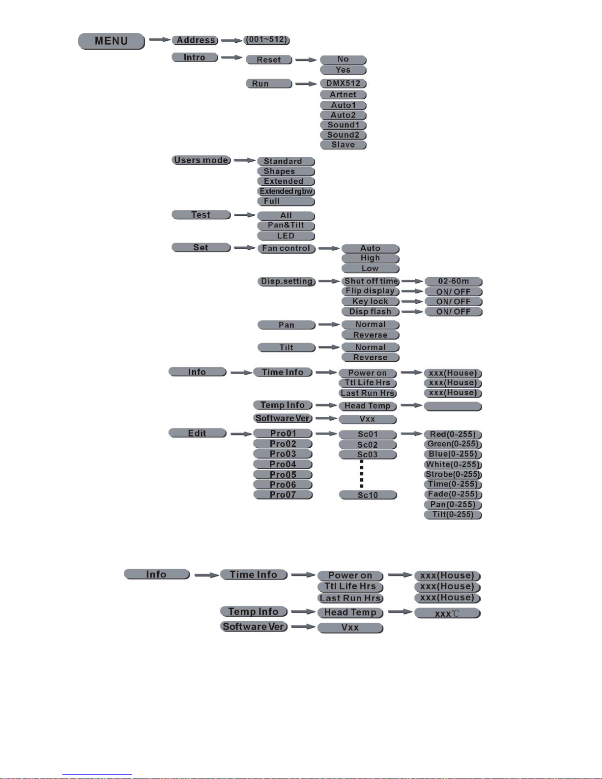
4) Menu Map
5) Info [Check equipment information]
●
Press MENU,until it shows【Info】,press ENTER.
●
Press UP or DOWN to choose 【Time Info】、【Temp Info】、【Software Ver】。
●
When selecting【Time Info】,press ENTER,prerss UP or DOWN to choose【Power on】,【Ttl Life hrs】
or【Last Run Hrs】,If choosing 【Power on】,press ENTER to enter into the equipment“XXXX”hours。If selecting
【Ttl Life hrs】,press ENTER to enter into the equipment total operation time“XXXX”hours,If selecting 【Last Run
Hrs】,press ENTER to show the LED’s last operation“XXXX”hours
●
When selecting【Temp Info】,press ENTER to show【Head Temp】,and then press
ENTER,it will show the head temperature“XXX°C”.
●
When selecting【Software Ver】,press ENTER ,it will show the equipment’software version.
Page 11
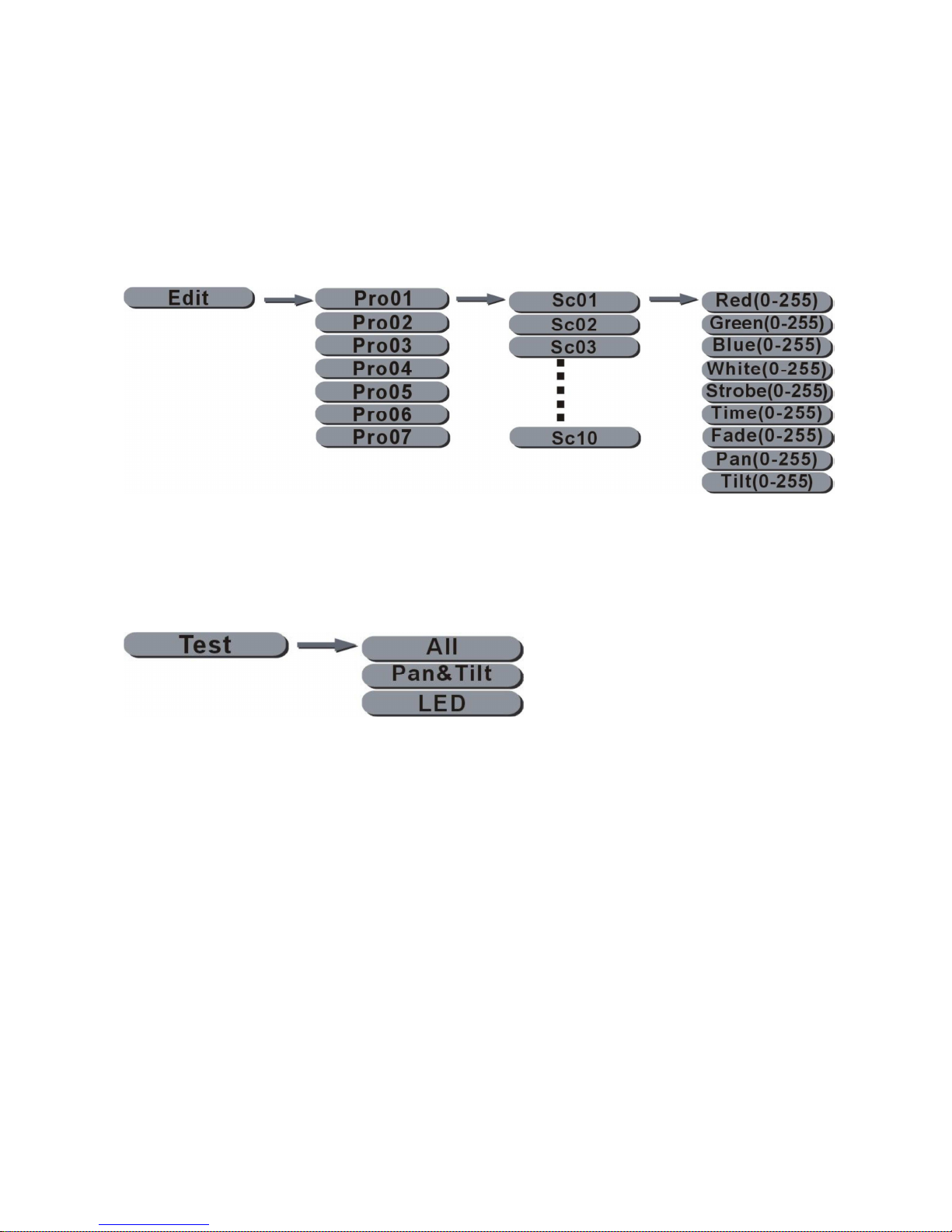
6) Custom Programs
●
The VK10 Vortex can store 7 custom programmable programs, each with 10 scenes and individual head positions and,
colours and fade times.
●
Press MENU,until it shows 【Edit】,and then press ENTER.
●
Press UP or DOWN to choose the program number to edit 【Pro01】-【Pro07】, and press ENTER,choose each
scene to edit【Sc01】-【Sc10】, press enter. and select the following parameters for each scene; 【Red 0-255】、
【
Green 0-255
】、【
Blue 0-255
】、【
White 0-255
】、【
Strobe 0-255
】、【
Time 0-255】【Fade 0-255
】、【
Pan
0-255
】、【
Tilt 0-255】.
Note: to leave a scene blank ie; not used then set time=0 otherwise there Must be a value greater than 0 in the time field
or the scene will not be included.
7) Test Procedure
●
Press MENU,until it shows 【Test】,and then press ENTER.
●
Press UP or DOWN to choose 【All
】、【
Pan&Tilt】 and 【LED】。Select 【All】,to test the motor and LED,
Select 【Pan&Tilt】 to test the motor,or 【LED】to test each led in functioning correctly
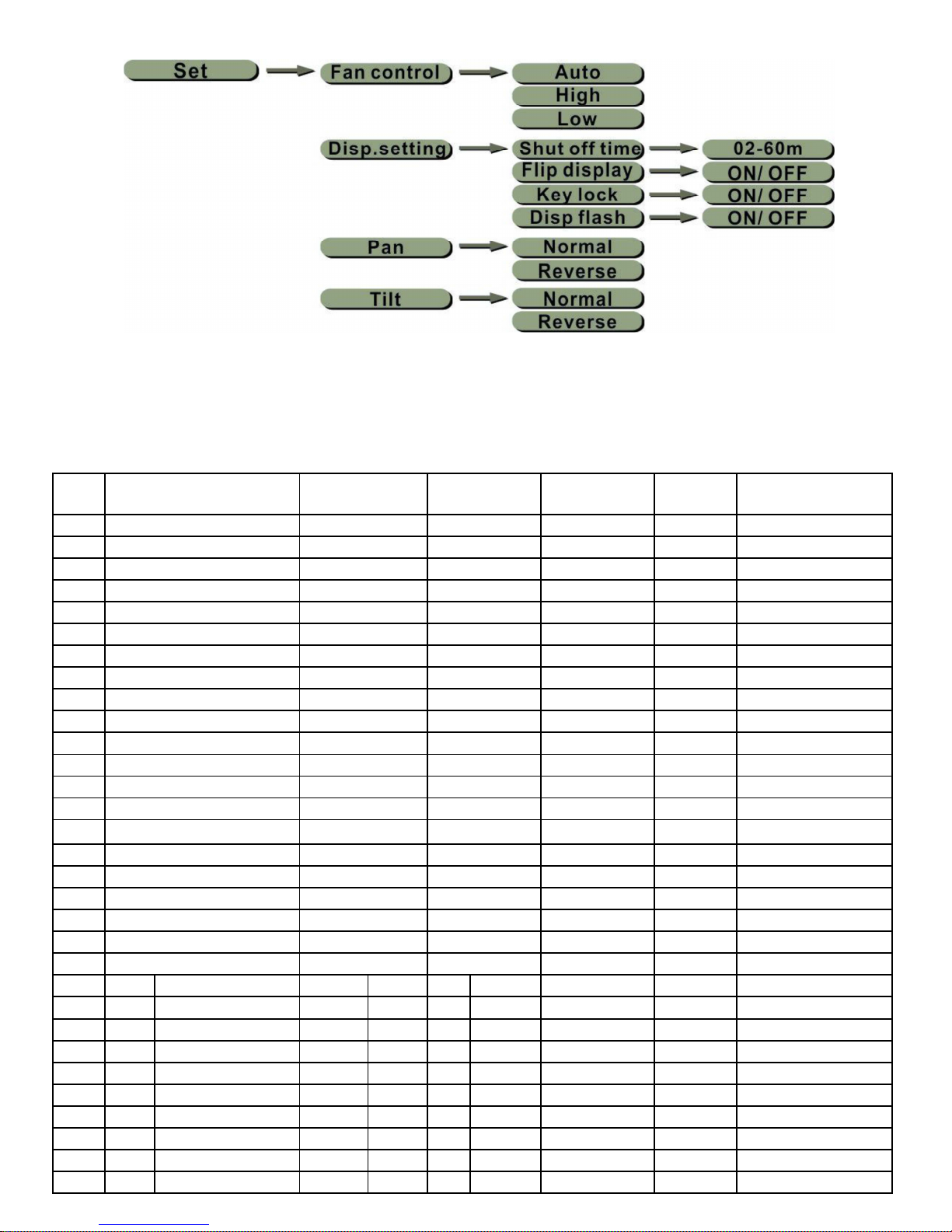
8) User Custom Operating Settings
●
Press MENU,until it shows【Set】,and then press ENTER.
●
Press UP or DOWN to choose 【Fan control】、【Disp.setting】、【Pan】、【Tilt】。
●
When selecting 【Fan control】,press ENTER,press UP or DOWN to choose the 3 kinds
of Fan control.【Auto】mode will according the lamp’s head to auto control the fan’s speed.
【High】mode is the fan’s high speed operation,【Low】mode is fan’s low speed
operation.
●
When selecting 【Disp.setting】,press ENTER,press UP or DOWN to choose 【Shut off
time】、【Flip display】、【Key lock】or 【Disp flash】,
If selecting【Shut off time】,press ENTER ,press UP or DOWN,it can be set LCD backlight close from 2-60 mins.
If selecting【Flip display】,press ENTER,press UP or DOWN,press【ON/OFF】to choose【ON】,the display will
then rotate through 180°。
When selecting【Key lock】,press ENTER,press UP or DOWN,press【ON/OFF】to choose【ON】,when the
backlight is off, the button keys are locked, & operation is invalid at this time. You must enter Up、Down、Up、Down
,
press ENTER to confirm the unlock.。
When selecting【Disp flash】,press ENTER,press UP or DOWN, choose【ON】 and the screen’s backlight begin to
blink when the equipment is receiving the DMX signal, The screen’s backlight will be off when there is no signal.
●
When selecting【Pan】or【Tilt】,press ENTER,operate UP or DOWN,Choose【Normal】or 【Reverse】to
set the forward and reverse operation
Page 12
9. DMX Protocol
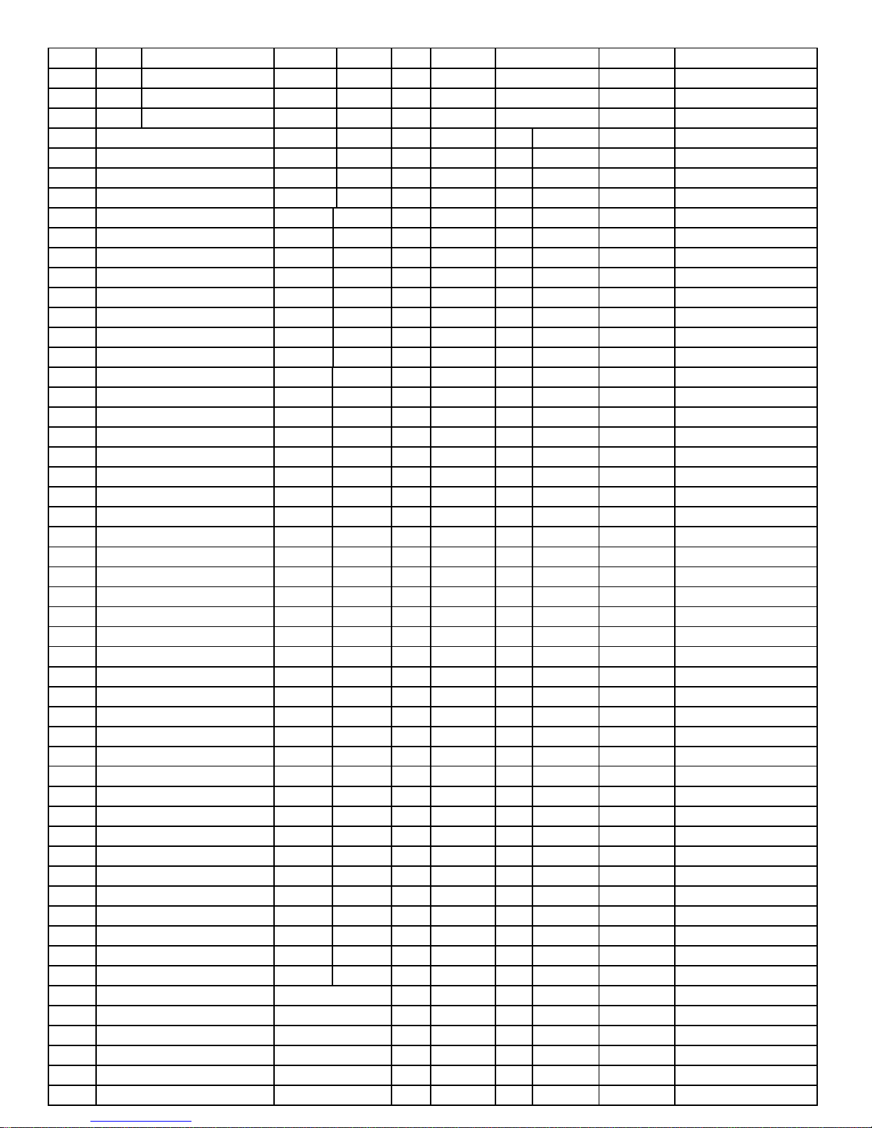
Sta
nda
Shapes Extended
Mode
Extended
RGBW Mode
Full
Mode
DMX
Value
Channel Function
1 1 1 1 1
0-255
Red
2 2 2 2 2
0-255
Red Fine
3 3 3 3 3
0-255
Green
4 4 4 4 4
0-255
Green Fine
5 5 5 5 5
0-255
Blue
6 6 6 6 6
0-255
Blue Fine
7 7 7 7 7
0-255
White
8 8 8 8 8
0-255
White Fine
9 9 9 9 9
0-255
Linear CTO Filter
10 10 10 10 10
0-255
Macro Colour
11 11 11 11 11
0-255
Strobe
12 12 12 12 12
0-255
Dimmer
13 13 13 13 13
0-255
Dimmer Fine
14 14 14 14 14
0-255
Pan
15 15 15 15 15
0-255
Pan Fine
16 16 16 16 16
0-255
Tilt
17 17 17 17 17
0-255
Tilt Fine
18 18 18 18 18
0-255
Function
19 19 19 19 19
0-255
Reset
20 20 20 20 20
0-255
Zoom
21 21 21 21 21
0-255
Zoom Rotation
22 Shape Selection
22
R Led 1
22
R Led 1
Shape Selection
23 Shape Sp
eed 23 G Led 1
23
G Led 1
Shape Sp
eed
24
Shape Fade
24
B Led 1
24
B Led 1
Shape Fade
25 Shape Red
25
R Led 2
25
W Led 1
Shape Red
26 Shape Green
26
G Led 2
26
R Led 2
Shape Green
27 Shape Blue
27
B Led 2
27
G Led 2
Shape Blue
28 Shape White
28 R Led 3
28
B Led 2
Shape White
29 Shape Dimmer
29
G Led 3
29
W Led 2
Shape Dimmer
30 Background Dimmer
30
B Led 3
30
R Led 3
Background
31 Shape Transition
31
R Led 4
31
G Led 3
Shape
Page 13
32 Shape Offset
32
G Led 4
32
B Led 3
Shape Offset
33 Foreground Strobe
33
B Led 4
33
W Led 3
Foreground
34 Background Strobe
34
R Led 5
34
R Led 4
Background
35 Background Select
35
G Led 5
35
G Led 4
Background
36 B Led 5
36
B Led 4
36
R Led 1
37 R Led 6
37
W Led 4
37
G Led 1
38 G Led 6
38
R Led 5
38
B Led 1
39 B Led 6
39
G Led 5
39
R Led 2
40 R Led 7
40
B Led 5
40
G Led 2
41 G Led 7
41
W Led 5
41
B Led 2
42 B Led 7
42
R Led 6
42
R
Led 3
43 R Led 8
43
G Led 6
43
G Led 3
44 G Led 8
44
B Led 6
44
B Led 3
45 B Led 8
45
W Led 6
45
R Led 4
46 R Led 9
46
R Led 7
46
G Led 4
47 G Led 9
47
G Led
7
47
B Led 4
48 B Led 9
48
B Led 7
48
R Led 5
49 R Led 10
49
W Led 7
49
G Led 5
50 G Led 10
50
R Led 8
50
B Led 5
51 B Led 10
51
G Led 8
51
R Led 6
52 R Led 11
52
B Led 8
52
G Led 6
53 G Led 11
53
W Led 8
53
B Led 6
54 B Led 11
54
R Led 9
54
R Led 7
55 R Led 12
55
G Led 9
55
G Led 7
56 G Led
12 56
B Led 9
56
B Led 7
57 B Led 12
57
W Led 9
57
R Led 8
58 R Led 13
58
R Led 10
58
G Led 8
59 G Led 13
59
G Led 10
59
B Led 8
60 B Led 13
60 B Led 10
60
R Led 9
61 R Led 14
61
W Led 10
61
G Led 9
62 G Led 14
62
R Led 11
62
B Led 9
63 B Led 14
63
G Led 11
63
R Led 10
64 R Led 15
64
B Led 11
64
G Led 10
65 G Led 15
65
W Led 11
65
B Led 10
66 B Led 15
66
R Led 12
66
R Led 11
67 R Led 16
67
G Led 12
67
G Led 11
68 G Led 16
68
B Led 12
68
B Led 11
69 B Led 16
69
W Led 12
69
R Led 12
70 R Led 17
70
R Led 13
70
G Led
12
71 G Led 17
71
G Led 13
71
B Led 12
72 B Led 17
72
B Led 13
72
R Led 13
73 R Led 18
73
W Led
13 73 G Led 13
74 G Led 18
74
R Led 14
74
B Led 13
75 B Led 18
75
G Led 14
75
R Led 14
76 R Led 19
76
B Led 14
76
G Led 14
77 G Led 19
77
W Led
14 77 B Led 14
78 B Led 19
78
R Led 15
78
R Led 15
79
G Led 15
79
G Led 15
80
B Led 15
80
B Led 15
81
W Led 15
81
R Led 16
82
R Le
d 16 82 G Led 16
83
G Led 16
83
B Led 16
84
B Led
16 84 R Led 17
Page 14
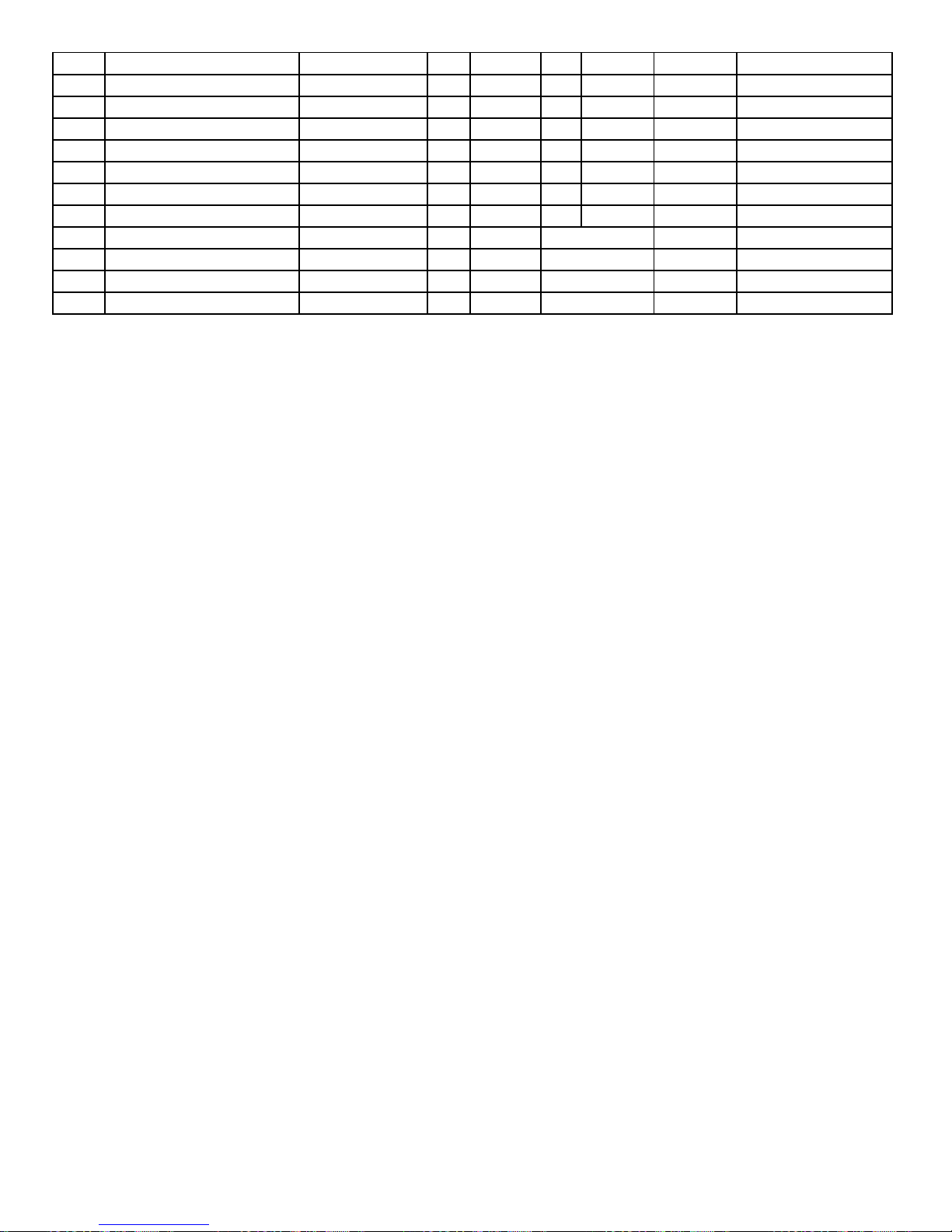
85
W Led 16
85
G Led 17
86
R Led 17
86
B Led 17
87
G Led 17
87
R Led 18
88
B Led 17
88
G Led 18
89
W Led 17
89
B Led 18
90
R Led 18
90
R Led 19
91
G Led 18
91
G Led 19
92
B Led 18
92
B Led 19
93
W Led 19
94
R Led 19
95
G Led 19
96
B Led 19
 Loading...