

Page 1
Installation
GUIDE
®
5 SERIES
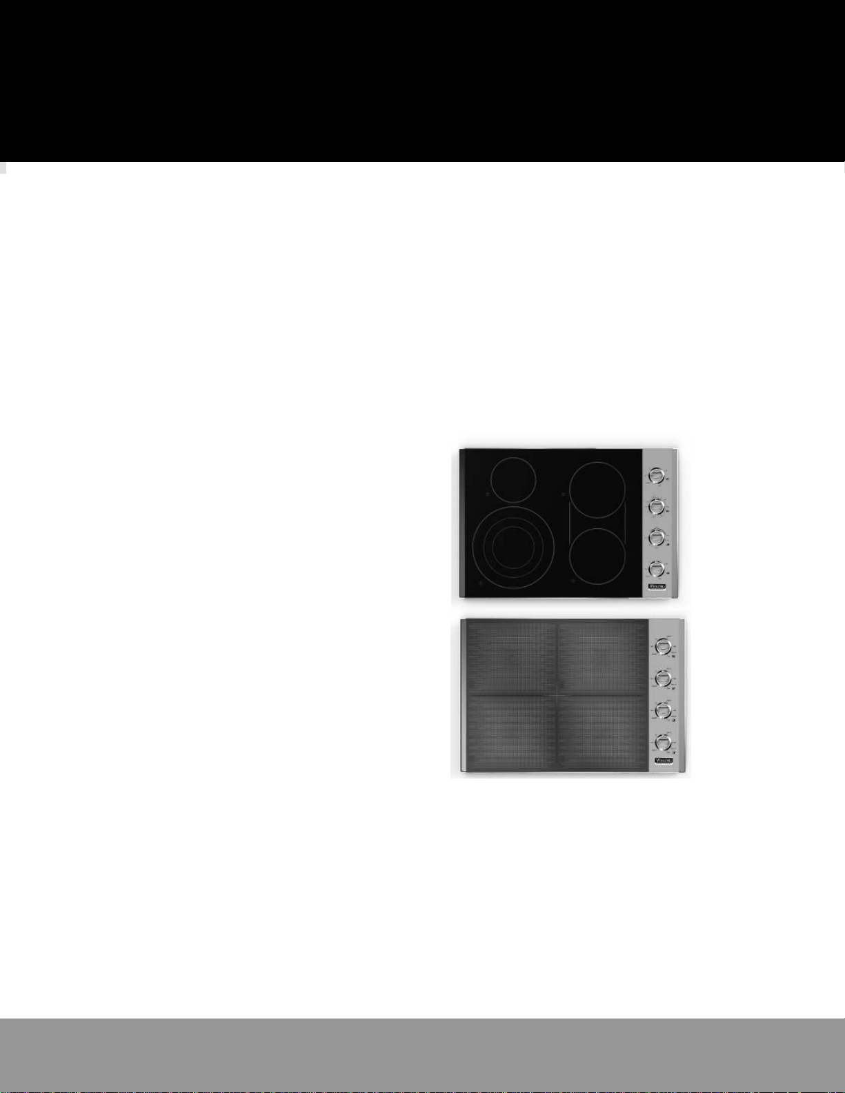
Built-In Electric Cooktops
Built-In Induction Cooktops
VEC530 / CVEC530 / VEC536 / CVEC536
VECU530 / CVEC
VIC530 / CVIC530 / VIC536 / CVIC536
VICU530 / CVICU530 / VICU536 / CVICU536
U530 / VECU536 / CVECU536
Page 2
Table of Contents
Warnings & Important Safety Instructions ___________________________3
Specifi cations /Dimensions (Electric Cooktops) ______________________4
Specifi cations /Dimensions (Induction Cooktops) ____________________8
Cutout Dimensions _____________________________________________12
Clearance Dimensions ___________________________________________13
Electrical Requirements __________________________________________15
General Information _____________________________________________16
Installation _____________________________________________________16
Final Preparation _______________________________________________17
Performance Checklist ___________________________________________17
Service & Registration ___________________________________________18
• Before beginning, please read these instructions completely and carefully.
Your safety and the safety of others is
very important.
We have provided many important safety
messages in this manual and on your
appliance. ALWAYS read and obey all
safety messages.
This is the safety alert symbol. This
symbol alerts you to hazards that
can kill or hurt you and others.
All safety messages will be
preceded by the safety alert symbol and
the word “DANGER,” “WARNING” or
“CAUTION.” These words mean:
Hazards or unsafe practices
which WILL result in severe personal
Hazards or unsafe practices
which COULD result in severe
personal injury or death
Hazards or unsafe practices which
COULD result in minor personal injury
All safety messages will identify the
hazard, tell you how to reduce the chance
of injury, and tell you what can happen if
the instructions are not followed.
DANGER
injury or death
WARNING
CAUTION
or property damage.
2
Page 3
IMPORTANT – Please Read and Follow!
• DO NOT remove permanently affi xed labels, warnings, or plates from product. This may void the
warranty.
• Please observe all local and national codes and ordinances. Installation must conform with local
codes and National Fuel Gas Code ANSIZ233.1/NFPA-54–latest edition.
• Please ensure that this product is properly grounded.
• The installer must leave these instructions with the consumer who should retain for local
inspector’s use and for future reference.
• Installation must conform with local codes or, in the absence of codes, the National Electrical
Code, ANSI/NFPA 70-latest edition.
In Canada: Electrical installation must be in accordance with the current CSA C22.1 Canadian
Electrical Codes Part 1 and/or local codes.
WARNING
BURN HAZARD
The use of cabinets for storage
above the appliance may result
in potential burn hazard. Combustible items
may ignite, metallic items may become hot
and cause burns. If a cabinet storage is to
provided the risk can be reduced by installing
a range hood that projects horizontally a
minimum of 5" (12.7 cm) beyond the bottom
of the cabinets.
WARNING
ELECTRICAL GROUNDING
INSTRUCTIONS
This cooktop must be electrically
grounded in accordance with local codes
or, in the absence of codes, with the
National Electrical Code, ANSI/NFPA 70latest edition. FOR PERSONAL SAFETY,
THIS APPLIANCE MUST BE PROPERLY
GROUNDED.
CAUTION
Be sure the electric power is
off from the breaker box to the
junction box until the cooktop is
installed and ready to operate. The junction
box should be connected to a suitable ground.
WARNING
The electrical power to the unit must
be shut off while line connections are
being made. Failure to do so could
result in serious injury or death.
WARNING
FIRE AND ELECTRICAL
SHOCK HAZARD
DO NOT use an extension cord with
this appliance. Such use may result
in fi re, electrical shock, or other
personal injury.
WARNING
The power supply board is provided with
the power supply, type RAC03-24SC/277,
manufactured by Recom, rated Input 100277Vac, Output 24V/125mA is UL recognized
under QAQGQ2/8.E224736. The external
overcurrent protection of the primary for this
power supply is max.20A.
WARNING
Stationary appliances not fi tted with means
for disconnection from the supply mains
having a contact separation in all poles that
provide full disconnection under overvoltage
category III, the insrtuctions shall state
that means for disconnection must be
incorporated in the fi xed wiring in accordance
with the wiring rules.
33
Page 4

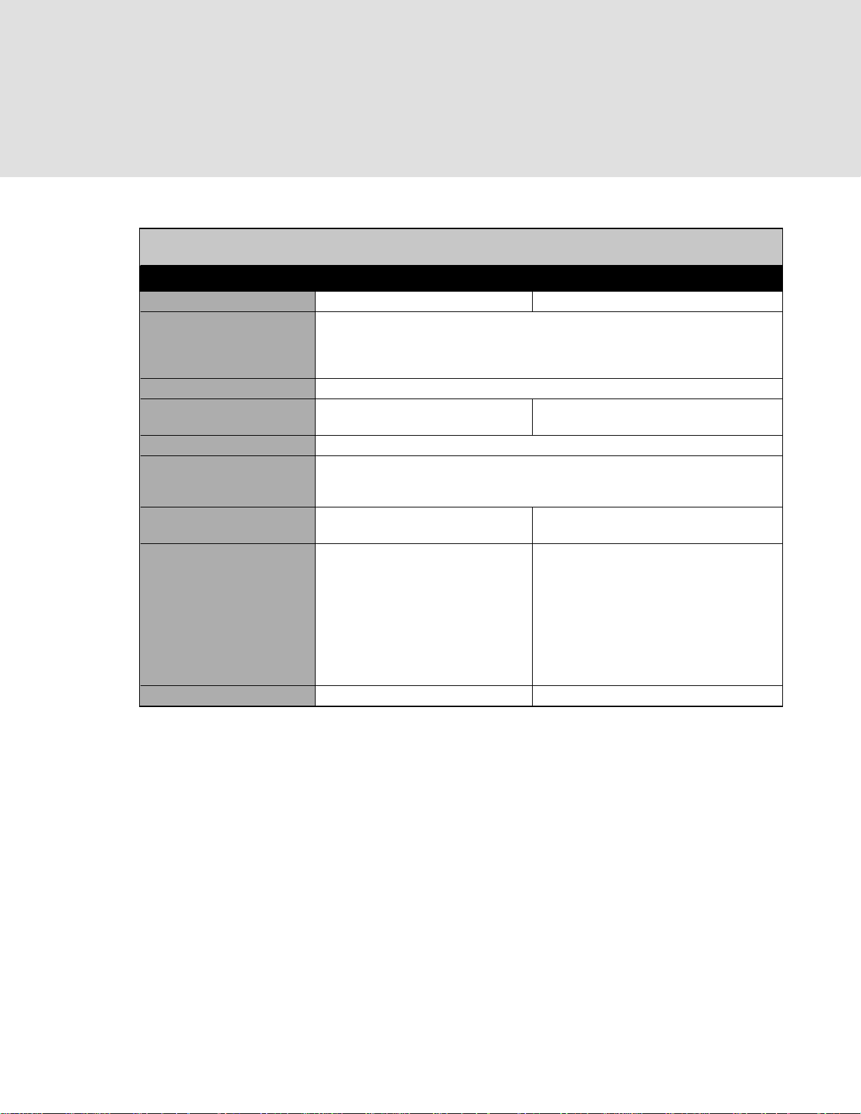
Specifi cations (VEC Electric Cooktops)
VEC Electric Cooktop
Description 30” W. - 76 cm Wide 36” W. - 91 cm Wide
Overall width 30-3/4” (78.1 cm) 36-3/4” (93.3 cm)
Overall height from bottom
To top of knobs
To top of cooking surface
To bottom edge of frame
Overall depth from rear 21” (53.3 cm)
Cutout width 28-7/8” (73.3 cm) minimum to
29-1/8” (74.0 cm) maximum
Cutout depth 19-1/4” (48.9 cm) minimum to 19-3/4” (50.2 cm) maximum
Electrical requirements 240-208/120 VAC; 50/60Hz; factory-installed 4 ft. (121.9 cm)
fl exible steel conduit 3-wire conduit with a No. 10 ground wire; located on the
Maximum amp usage 240V—36.6 amps (8.8 kw)
208V—31.7 amps (6.6 kw)
Surface element rating
Right front
Right rear
Center front
Center rear
Left front
Left rear
Bridge
Approximate shipping Wt w 44 lb. (20.0 kg) 53 lb. (24.1 kg)
8-1/2” (21.6 cm) -1,800 W
8-1/2” (21.6 cm) -1,800 W
N/A
N/A
12” (30.5 cm) triple - 1100 W/ 1000
W/1100 W
6-1/2” (16.5 cm) -1,200 W
800 W
4-3/4” (12.1 cm)
3-1/2” (8.9 cm)
2-5/8” (6.7 cm)
34-7/8” (88.6 cm) minimum to
35-1/8” (89.2 cm) maximum
right rear corner of unit
240V—45.0 amps (10.8 kw)
208V—38.9 amps (8.1 kw)
6-1/2” (16.5 cm) -1,200 W
8-1/2” (21.6 cm) dual -1,000 W/1000 W
8-1/2” (21.6 cm) -1,800 W
8-1/2” (21.6 cm) -1,800 W
12” (30.5 cm) triple - 1100 W/
1000 W/1100 W
6-1/2” (16.5 cm) -1,200 W
800 W
4
Page 5
Dimensions (VEC Electric Cooktops)
30” W. (76
30-3/4”
(78.1 cm)
cm) Cooktop
36” W. (91 cm) Cooktop
21”
(53.4 cm)
36-3/4”
(93.3 cm)
21”
(53.4 cm)
4”
(10.2 cm)
4-3/4”
(12.1 cm)
2-5/8”
(6.7 cm)
3-1/2”
(8.9 cm)
5
Page 6
Specifi cations (VECU Electric Cooktops)
VECU Electric Cooktop
Description 30” W. - 76 cm Wide 36” W. - 91 cm Wide
Overall width 30-3/4” (78.1 cm) 36-3/4” (93.3 cm)
Overall height from bottom
To top of knobs
To top of cooking surface
To bottom edge of frame
Overall depth from rear 21” (53.3 cm)
Cutout width 28-7/8” (73.3 cm) minimum to
29-1/8” (74.0 cm) maximum
Cutout depth 19-1/4” (48.9 cm) minimum to 19-3/4” (50.2 cm) maximum
Electrical requirements 240-208/120 VAC; 50/60Hz; factory-installed 4 ft. (121.9 cm)
fl exible steel conduit 3-wire conduit with a No. 10 ground wire; located on the
Maximum amp usage 240V—36.6 amps (8.8 kw)
208V—31.7 amps (6.6 kw)
Surface element rating
Right front
Right rear
Center front
Center rear
Left front
Left rear
Bridge
Approximate shipping Wt w 44 lb. (20.0 kg) 53 lb. (24.1 kg)
8-1/2” (21.6 cm) -1,800 W
8-1/2” (21.6 cm) -1,800 W
N/A
N/A
12” (30.5 cm) triple - 1100 W/ 1000
W/1100 W
6-1/2” (16.5 cm) -1,200 W
800 W
4-1/2” (11.4 cm)
3-1/2” (8.9 cm)
2-3/4” (7.0 cm)
34-7/8” (88.6 cm) minimum to
35-1/8” (89.2 cm) maximum
right rear corner of unit
240V—45.0 amps (10.8 kw)
208V—38.9 amps (8.1 kw)
6-1/2” (16.5 cm) -1,200 W
8-1/2” (21.6 cm) dual -1,000 W/1000 W
8-1/2” (21.6 cm) -1,800 W
8-1/2” (21.6 cm) -1,800 W
12” (30.5 cm) triple - 1100 W/
1000 W/1100 W
6-1/2” (16.5 cm) -1,200 W
800 W
6
Page 7

Dimensions (VECU Electric Cooktops)
30” W. (76
30-3/4”
(78.1 cm)
cm) Cooktop
36” W. (91 cm) Cooktop
21”
(53.4 cm)
36-3/4”
(93.3 cm)
21”
(53.4 cm)
3-3/8”
(8.6 cm)
4-1/2”
(11.4 cm)
2-3/4”
(7.0 cm)
3-1/2”
(8.9 cm)
7
Page 8

Specifi cations (VIC Induction Cooktops)
VIC Induction Cooktop
Description 30” W. - 76 cm Wide 36” W. - 91 cm Wide
Overall width 30-3/4” (78.1 cm) 36-3/4” (93.3 cm)
Overall height from bottom
To top of knobs
To top of cooking surface
To bottom edge of frame
Overall depth from rear 21” (53.3 cm)
Cutout width 28-1/2” (72.4 cm) minimum to
29” (73.7 cm) maximum
Cutout depth 19-3/8" (49.2 cm) minimum to 19-7/8" (50.5 cm) maximum
Electrical requirements 240-208/120 VAC; 50/60Hz; factory-installed 4 ft. (121.9 cm) fl exible steel
conduit 3-wire conduit with a No. 10 ground wire; located
on the right rear corner of unit
Maximum amp usage 240V—32.2 amps (7.7 kw)
208V—27.9 amps (5.8 kw)
Surface element rating (4) 9” (22.9 cm)
2300 W / 3,700 W boost
Approximate shipping
weight
52 lb. (23.6 kg) 63 lb. (28.6 kg)
4” (10.2 cm)
3” (7.6 cm)
2-1/8” (5.4 cm)
34-1/2” (87.6 cm) minimum to
35” (88.9 cm) maximum
240V—48.3 amps (11.6 kw)
208V—41.9 amps (8.7 kw)
(6) 9” (22.9 cm)
2300 W / 3,700 W boost
8
Page 9

Dimensions (VIC Induction Cooktops)
30” W. (76
30-3/4”
(78.1 cm)
cm) Cooktop
(53.4 cm)
21”
36” W. (91 cm) Cooktop
36-3/4”
(93.3 cm)
21”
(53.4 cm)
3-1/2”
(8.9 cm)
2-1/8”
(5.4 cm)
4”
(10.2 cm)
3”
(7.6 cm)
9
Page 10

Specifi cations (VICU Induction Cooktops)
VICU Induction Cooktop
Description 30” W. - 76 cm Wide 36” W. - 91 cm Wide
Overall width 30-3/4” (78.1 cm) 36-3/4” (93.3 cm)
Overall height from bottom
To top of knobs
To top of cooking surface
To bottom edge of frame
Overall depth from rear 21” (53.3 cm)
Cutout width 28-1/2” (72.4 cm) minimum to
29” (73.7 cm) maximum
Cutout depth 19-3/8" (49.2 cm) minimum to 19-7/8" (50.5 cm) maximum
Electrical requirements 240-208/120 VAC; 50/60Hz; factory-installed 4 ft. (121.9 cm) fl exible steel
conduit 3-wire conduit with a No. 10 ground wire; located
Maximum amp usage 240V—32.2 amps (7.7 kw)
208V—27.9 amps (5.8 kw)
Surface element rating (4) 9” (22.9 cm)
2300 W / 3,700 W boost
Approximate shipping
weight
52 lb. (23.6 kg) 63 lb. (28.6 kg)
4-1/16” (10.3 cm)
3” (7.6 cm)
2-5/16” (5.9 cm)
34-1/2” (87.6 cm) minimum to
35” (88.9 cm) maximum
on the right rear corner of unit
240V—48.3 amps (11.6 kw)
208V—41.9 amps (8.7 kw)
(6) 9” (22.9 cm)
2300 W / 3,700 W boost
10
Page 11

Dimensions (VICU Induction Cooktops)
30” W. (76
30-3/4”
(78.1 cm)
cm) Cooktop
36” W. (91 cm) Cooktop
21”
(53.4 cm)
36-3/4”
(93.3 cm)
21”
(53.4 cm)
3-5/8”
(9.2 cm)
2-5/16”
(5.9 cm)
4-1/16”
(10.3 cm)
3”
(7.6 cm)
11
Page 12

Cutout Dimensions
Electric
30”W. MODELS 36”W. MODELS
28-7/8” (73.3 cm) min. to
A
29-1/8” (74.0 cm) max.
B
30”W. MODELS 36”W. MODELS
28-1/2” (72.4 cm) min. to
A
29” (73.7 cm) max.
B
19-1/4” (48.9 cm) min. to
19-3/4” (50.2 cm) max.
Induction
19-3/8" (49.2 cm) min. to
19-7/8" (50.5 cm) max.
Note: Based on 24” deep cabinet with 3/4” backsplash.
34-7/8” (88.6 cm) min. to
35-1/8” (89.2 cm) max.
34-1/2” (87.6 cm) min. to
35” (88.9 cm) max.
B
A
(2.54 cm)*
1”
2-1/2”
to
(6.35 cm)*
30” W. (76 cm) Electric Cooktop
over 30” W. (76 cm) Electric Oven
36”min.
(91.4 cm)
28-1/8”
(71.4 cm)
(12.7 cm) max.
5”
Note: Refer to the oven installation instructions for
undercounter oven dimensions.
See B
Above
14-1/4”
(36.2 cm)
28-1/2”
(72.4 cm)
2-1/2” min.
(6.4 cm)
14-3/8”
(36.5 cm)
(36.5 cm)
14-1/4”
(36.2 cm)
14-3/8”
See A
Above
12
Page 13

Headline
Clearance Dimensions
PROXIMITY TO SIDE CABINET
INSTALLATION
• The cooktop may be installed directly to
existing base cabinets.
• The cooktop CANNOT be installed
directly adjacent to sidewalls, tall cabinets,
tall appliances, or other side vertical
surfaces above 36” (91.4 cm) high. There
must be a minimum of 6” (15.2 cm) side
clearance from the cooktop to such
combustible surfaces above the 36”
(91.4 cm) counter height.
• Within the 6” (15.2 cm) side clearance to
combustible vertical surfaces above
36” (91.4 cm), the maximum wall cabinet
depth must be 13” (33.0 cm) and wall
cabinets within this 6” (15.2 cm) side
clearance must be 18” (45.7 cm) above
the 36” (91.4 cm) high countertop.
• Wall cabinet above the cooktop must be
a minimum of 36” (91.4 cm) above the
countertop for a full width of the cooktop.
• If a ventilation hood is installed over the
cooktop, the minimum 36” (91.4 cm)
height clearance above the unit does not
apply. Refer to the hood installation
instructions for further information.
Minimum Clearances from Adjacent
Combustible Construction
• Above countertop 36” (91.4 cm) minimum
• Side 6” (15.2 cm)
• Rear 0” (0.0 cm)
• Within 6” side clearance. Wall cabinets no
deeper than 13” (33.0 cm)
• Must be minimum 18” (45.7 cm) above
countertop
• Wall cabinets directly above the product
must be minimum 36” (91.4 cm) above the
countertop
For Brazil/Mexico Only: It is
recommended that a removable shelf be
installed under the appliance after it has
been fully installed to prevent
unintended access to the appliance
during use.
Note: Dimensions shown are for use
with combustible surfaces unless
otherwise stated.
13
13
Page 14

Headline
Clearance Dimensions
INTERIOR CABINET CLEARANCES
INDUCTION COOKTOPS
IMPORTANT: The electronic components
for the induction elements in the cooktop
need air circulation. To ensure long life of
electronic components, it is required that
1-1/2 (3.8 cm) or more open space remains
between the bottom of the cooktop and any
shelf underneath. The maximum length of
the shelf underneath is 18” (45.7 cm). It is
required that the exit air ports at the front are
not blocked.
WOOD/COMPOSITE OVERLAY
The bottom of a standard hood should be
30” (76.2 cm) min. to 36” (91.4 cm) max.
above the countertop. This would typically
result in the bottom of the hood being
66” (167.6 cm) to 72” (182.9 cm) above the
fl oor. Refer to the rangehood installation
instructions for additional information. These
dimensions provide for safe and effi cient
operation of the hood.
14
14
Page 15

Headline
Electrical Requirements
WARNING
BURN HAZARD
The use of cabinets for storage
above the appliance may result
in potential burn hazard. Combustible
items may ignite, metallic items may
become hot and cause burns. If a cabinet
storage is to provided the risk can be
reduced by installing a range hood that
projects horizontally a minimum of 5" (12.7
cm) beyond the bottom of the cabinets.
Electrical Requirements
Check your local codes regarding this unit.
This cooktop is supplied with a 3-wire, A.C.
208V/120 volt or 120V/240 volt, 60 HZ
electrical system. A white (neutral) is not
needed for this unit. See next section for
grounding instructions. It should be fused
separately.
CAUTION
Be sure the electric power is
off from the breaker box to the
junction box until the cooktop
is installed and ready to operate. The
junction box should be connected to a
suitable ground.
WARNING
The electrical power to the
unit must be shut off while line
connections are being made.
Failure to do so could result in serious
injury or death.
Electrical Connection
When making the wire connections, use
the entire length of the conduit provided
(4 feet). The conduit must not be cut.
Connect the red and black leads from the
unit conduit to the corresponding leads in
the junction box. The bare ground wire in the
conduit is connected to the unit frame. When
connecting to a 3-conductor branch circuit,
connect the bare ground connector lead of
the unit to the branch circuit ground (bare
wire or green in color).
WARNING
FIRE AND ELECTRICAL
SHOCK HAZARD
DO NOT use an extension
cord with this appliance. Such
use may result in fi re, electrical
shock, or other personal injury.
Refer to the specifi cations chart for kilowatt
rating and recommended amperage. House
wiring and fusing must comply with local
codes. If no local codes are applicable, wire
in accordance with the National Electrical
Code, ANSI/NFPA 70-latest edition.
15
15
Page 16

Headline
General Information
READ AND FOLLOW ALL WARNING
AND CAUTION INFORMATION WHEN
INSTALLING THIS APPLIANCE.
• Keep appliance area clear and free from
combustible materials, gasoline and other
fl ammable vapors.
• Disconnect the electrical supply prior to
servicing or cleaning.
Installation
1
• When removing the cooktop for service
and/or cleaning, disconnect AC power
supply.
• Electrical requirements are listed in the
product specifi cations under the “Electrical
Requirements” section.
2
Ground
Red
Green
Black
Lower cooktop into cutout. Connect the red and black leads from the unit conduit
3
Cooktop
Screw
Screw brackets to burner box with sheet metal screw.
(Two bracket assemblies included)
Cooktop
Bracket
Countertop
Eye Bolt
16
16
to the corresponding leads in the junction box.
4
Screw eye bolt into brackets
and tighten fi rmly against bottom of countertop.
Note: Be careful not to crack or damage
counter by overtightening.
Page 17

Headline
Final Preparation
• Some stainless steel parts may have plastic
protective wrap which must be peeled off.
• All stainless steel body parts should be
wiped with hot, soapy water and with a
liquid cleaner designed for this material.
If buildup occurs, DO NOT use steel wool,
abrasive cloths, cleaners, or powders!
• If it is necessary to scrape stainless steel to
remove encrusted materials, soak with hot,
wet cloths to loosen the material, then use
a wood or nylon scraper. DO NOT use a
metal knife, spatula, or any other metal
tool to scrape stainless steel! Scratches are
almost impossible to remove.
Performance Checklist
A qualifi ed installer should carry out the
following checks:
Check top surface elements
1. Starting with the left front element,
turn the corresponding knob to the
HI position—left front indicator should
fl ash.
2. Place an induction compatible piece
of cookware onto the left front
burner—left front indicator should be
solid.
3. Remove cookware and repeat steps
for other elements.
17
17
Page 18

Headline
Service & Registration
Only authorized replacement parts may be used in performing service on the cooktop.
DO NOT repair or replace any part of the appliance unless specifi cally recommended in the
manual. All other servicing should be referred to a qualifi ed technician.
Contact Viking Range, LLC, 1-888-(845-4641), for the nearest service parts distributor in your
area or write to:
VIKING RANGE, LLC
PREFERRED SERVICE
111 Front Street
Greenwood, Mississippi 38930 USA
Cooktop – The serial number and model number for your appliance can be found by looking
under the unit.
Record the information indicated below. You will need it if service is ever required.
Model number ________________________________________________________________________
Serial number _________________________________________________________________________
Date of purchase ______________________________________________________________________
Date installed _________________________________________________________________________
Dealer’s name ________________________________________________________________________
Address ______________________________________________________________________________
These installation instructions should remain with the unit for future reference.
18
18
Page 19

19
Page 20

Viking Range, LLC
111 Front Street
Greenwood, Mississippi 38930 USA
(662) 455-1200
For product information,
call 1-888-(845-4641) or
visit our web site at vikingrange.com in the US or
brigade.ca in Canada
F21271E EN
(013117)
 Loading...