

Viking VHSO205SS Service Manual
VIKING
SERVICE MANUAL
HIGH SPEED CONVECTION
MICROWAVE OVEN
MODEL
VHSO205SS
VHSO205SS
S17M273VHS205
In the interest of user-safety the oven should be restored to its original condition and only parts identical to those specifi ed should
be used.
WARNING TO SERVICE PERSONNEL: Microwave ovens contain circuitry capable of producing very high voltage and
current, contact with following parts may result in a severe, possibly fatal, electrical shock. (High Voltage Capacitor,
High Voltage Power Transformer, Magnetron, High Voltage Rectifi er Assembly, High Voltage Harness etc..)
TABLE OF CONTENTS
Page
PRECAUTIONS TO BE OBSERVED BEFORE AND DURING SERVICE TO
AVOID POSSIBLE EXPOSURE TO EXCESSIVE MICROWAVE ENERGY ..................... INSIDE FRONT COVER
BEFORE SERVICING ....................................................................................................... INSIDE FRONT COVER
WARNING TO SERVICE PERSONNEL ................................................................................................................. 3
MICROWAVE MEASUREMENT PROCEDURE ..................................................................................................... 4
FOREWORD AND WARNING ............................................................................................................................... 5
PRODUCT SPECIFICATIONS ...............................................................................................................................6
GENERAL INFORMATION.................................................................................................................................... 6
OPERATION ........................................................................................................................................................... 8
TROUBLESHOOTING GUIDE ............................................................................................................................. 15
TEST PROCEDURE ............................................................................................................................................ 17
TOUCH CONTROL PANEL .................................................................................................................................. 28
PRECAUTIONS FOR USING LEAD-FREE SOLDER .......................................................................................... 32
COMPONENT REPLACEMENT AND ADJUSTMENT PROCEDURE.................................................................33
PICTORIAL DIAGRAM ......................................................................................................................................... 41
POWER UNIT CIRCUIT ....................................................................................................................................... 42
CPU UNIT CIRCUIT ............................................................................................................................................. 43
PARTS LIST ......................................................................................................................................................... 44
PACKING AND ACCESSORIES ..........................................................................................................................49
This document has been published to be used for after sales service only. The contents are subject to
change without notice.
Range Corporation
111 Front St., Greenwood, MS 38930
Tel: (888) 845-4641
1

VHSO205SS
PRECAUTIONS TO BE OBSERVED BEFORE AND
DURING SERVICING TO AVOID POSSIBLE EXPOSURE TO EXCESSIVE MICROWAVE ENERGY
(a) Do not operate or allow the oven to be operated with the door open.
(b) Make the following safety checks on all ovens to be serviced before activating the magnetron or other
microwave source, and make repairs as necessary: (1) interlock operation, (2) proper door closing, (3)
seal and sealing surfaces (arcing, wear, and other damage), (4) damage to or loosening of hinges and
latches, (5) evidence of dropping or abuse.
(c) Before turning on microwave power for any service test or inspection within the microwave generating
compartments, check the magnetron, wave guide or transmission line, and cavity for proper alignment,
integrity, and connections.
(d) Any defective or misadjusted components in the interlock, monitor, door seal, and microwave genera
tion and transmission systems shall be repaired, replaced, or adjusted by procedures described in this
manual before the oven is released to the owner.
(e) A microwave leakage check to verify compliance with the Federal Performance Standard should be
performed on each oven prior to release to the owner.
-
BEFORE SERVICING
Before servicing an operative unit, perform a microwave emission check as per the Microwave
Measurement Procedure outlined in this service manual.
If microwave emissions level is in excess of the specified limit, contact Viking Service immediately
@ 1-888-845-4641.
If the unit operates with the door open, service person should (1) tell the user not to operate the
oven and (2) contact VIKING, plus the Department Of Health, Canada and/or the Food and Drug
Administration's Center for Devices and Radiological Health immediately.
Service personnel should inform VIKING of any certified unit found with emissions in excess of
4mW/cm2. The owner of the unit should be instructed not to use the unit until the oven has been
brought into compliance.
2
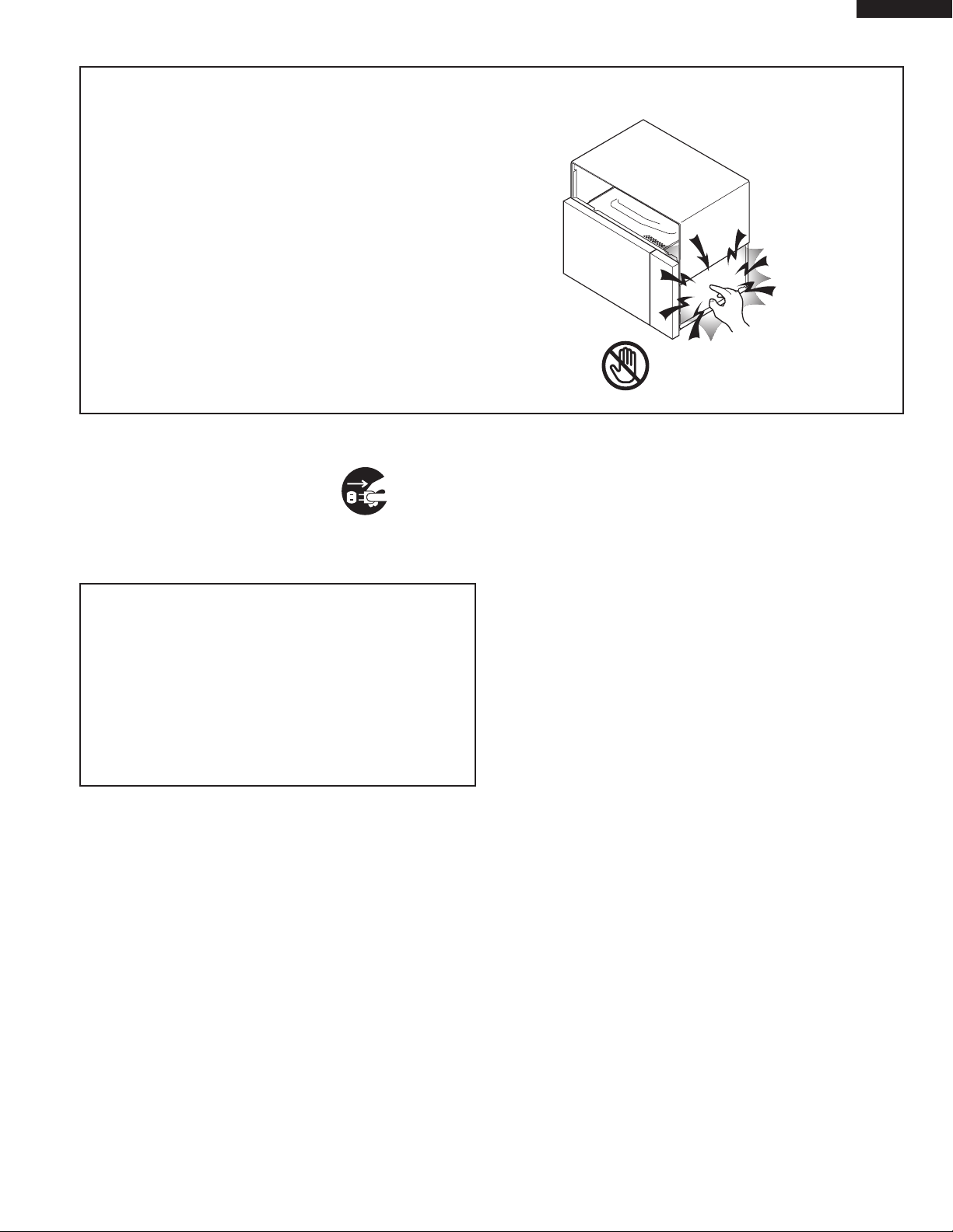
WARNING TO SERVICE PERSONNEL
Don't Touch !
Danger High Voltage
Microwave ovens contain circuitry capable of producing very high voltage and current, contact with
following parts
fatal, electrical shock.
(Example)
High Voltage Capacitor, High Voltage Power
Transformer, Magnetron, High Voltage Rectifier
Assembly, High Voltage Harness etc..
Read the Service Manual carefully and follow all
instructions.
may result in a severe, possibly
VHSO205SS
Before Servicing
1. Disconnect the power supply cord , and then
remove outer case.
2. Open the door and block it open.
3. Discharge high voltage capacitor.
WARNING: RISK OF ELECTRIC SHOCK.
DISCHARGE THE HIGH-VOLTAGE
CAPACITOR BEFORE SERVICING.
The high-voltage capacitor remains charged about 60
seconds after the oven has been switched off. Wait for
60 seconds and then short-circuit the connection of the
high-voltage capacitor (that is the connecting lead of the
high-voltage rectifier) against the chassis with the use of
an insulated screwdriver.
Whenever troubleshooting is performed the power supply
must be disconnected. It may, in some cases, be necessary
to connect the power supply after the outer case has been
removed, in this event,
1. Disconnect the power supply cord, and then remove
outer case.
2. Open the door and block it open.
3. Discharge high voltage capacitor.
4. Disconnect the leads to the primary of the power
transformer.
5. Ensure that the leads remain isolated from other
components and oven chassis by using insulation
tape.
6. After that procedure, reconnect the power supply cord.
When the testing is completed,
1. Disconnect the power supply cord, and then remove
outer case.
2. Open the door and block it open.
3. Discharge high voltage capacitor.
4. Reconnect the leads to the primary of the power
transformer.
5. Reinstall the outer case (cabinet).
6. Reconnect the power supply cord after the outer case
is installed.
7. Run the oven and check all functions.
After repairing
1. Reconnect all leads removed from components during
testing.
2. Reinstall the outer case (cabinet).
3. Reconnect the power supply cord after the outer case
is installed.
4. Run the oven and check all functions.
Microwave ovens should not be run empty. To test for the
presence of microwave energy within a cavity, place a cup
of cold water on the oven turntable, close the door and set
the power to HIGH and set the microwave timer for two (2)
minutes. When the two minutes has elapsed (timer at zero)
carefully check that the water is now hot. If the water remains
cold carry out Before Servicing procedure and re-examine
the connections to the component being tested.
When all service work is completed and the oven is fully
assembled, the microwave power output should be checked
and a microwave leakage test should be carried out.
3

VHSO205SS
MICROWAVE MEASUREMENT PROCEDURE
A. Requirements:
1) Microwave leakage limit (Power density limit): The power density of microwave radiation emitted by a microwave
oven should not exceed 1mW/cm2 at any point 5cm or more from the external surface of the oven, measured prior to
acquisition by a purchaser, and thereafter (through the useful life of the oven), 5 mW/cm2 at any point 5cm or more
from the external surface of the oven.
2) Safety interlock switches: Primary interlock relay and door sensing switch shall prevent microwave radiation emission in
excess of the requirement as above mentioned, secondary interlock switch shall prevent microwave radiation emission
in excess of 5 mW/cm2 at any point 5cm or more from the external surface of the oven.
B. Preparation for testing:
Before beginning the actual measurement of leakage, proceed as follows:
1) Make sure that the actual instrument is operating normally as specified in its instruction booklet.
Important:
Survey instruments that comply with the requirement for instrumentation as prescribed by the performance standard for
microwave ovens, 21 CFR 1030.10(c)(3)(i), must be used for testing.
2) Place the oven tray in the oven cavity.
3) Place the load of 275±15 ml (9.8 oz) of tap water initially at 20±5οC (68οF) in the center of the oven cavity.
The water container shall be a low form of 600 ml (20 oz) beaker with an inside diameter of approx. 8.5 cm (3-1/2 in.)
and made of an electrically nonconductive material such as glass or plastic.
The placing of this standard load in the oven is important not only to protect the oven, but also to insure that any leakage
is measured accurately.
4) Set the cooking control on Full Power Cooking Mode.
5) Close the door and select a cook cycle of several minutes. If the water begins to boil before the survey is completed,
replace it with 275 ml of cool water.
C. Leakage test:
Closed-door leakage test (microwave measurement)
1) Grasp the probe of the survey instrument and hold it perpendicular to the gap between the door and the body of the
oven.
2) Move the probe slowly, not faster than 1 in./sec. (2.5 cm/sec.) along the gap, watching for the maximum indication on
the meter.
3) Check for leakage at the door screen, sheet metal seams and other accessible positions where the continuity of the
metal has been breached (eg., around the switches, indicator, and vents).
While testing for leakage around the door pull the door away from the front of the oven as far as is permitted by the
closed latch assembly.
4) Measure carefully at the point of highest leakage and make sure that the highest leakage is no greater than 4mW/cm2,
and that the secondary interlock switch does turn the oven OFF before any door movement.
4
SERVICE MANUAL
VIKING
MICROWAVE OVEN
VHSO205SS
VHSO205SS
PRODUCT DESCRIPTION
FOREWORD
This Manual has been prepared to provide VIKING Products.
Personnel with Operation and Service Information for the VIKING
HIGH SPEED MICROWAVE OVEN, VHSO205SS.
It is recommended that service personnel carefully study the entire
text of this manual so that they will be qualified to render satisfactory
customer service.
Check the interlock switches and the door seal carefully. Special
attention should be given to avoid electrical shock and microwave
radiation hazard.
WARNING
Never operate the oven until the following points are ensured.
(A) The door is tightly closed.
(B) The door brackets and hinges are not defective.
(C) The door packing is not damaged.
(D) The door is not deformed or warped.
(E) There is not any other visible damage with the oven.
Service
GENERAL INFORMATION
OPERATION
TROUBLESHOOTING GUIDE
AND TEST PROCEDURE
TOUCH CONTROL PANEL
COMPONENT REPLACEMENT AND
ADJUSTMENT PROCEDURE
WIRING DIAGRAM
Servicing and repair work must be carried out only by trained service
personnel.
DANGER
Certain initial parts are intentionally not grounded and present
a risk of electrical shock only during servicing. Service
personnel - Do not contact the following parts while the appliance is energized;
High Voltage Capacitor, Power Transformer, Magnetron, High
Voltage Rectifier Assembly, High Voltage Harness;
If provided, Vent Hood, Fan assembly, Cooling Fan Motor.
All the parts marked “*” on parts list are used at voltages more
than 250V.
Removal of the outer wrap gives access to voltage above 250V.
All the parts marked “ ” on parts list may cause undue microwave
exposure, by themselves, or when they are damaged, loosened
or removed.
VIKING Range Corporation
PARTS LIST
5
VHSO205SS
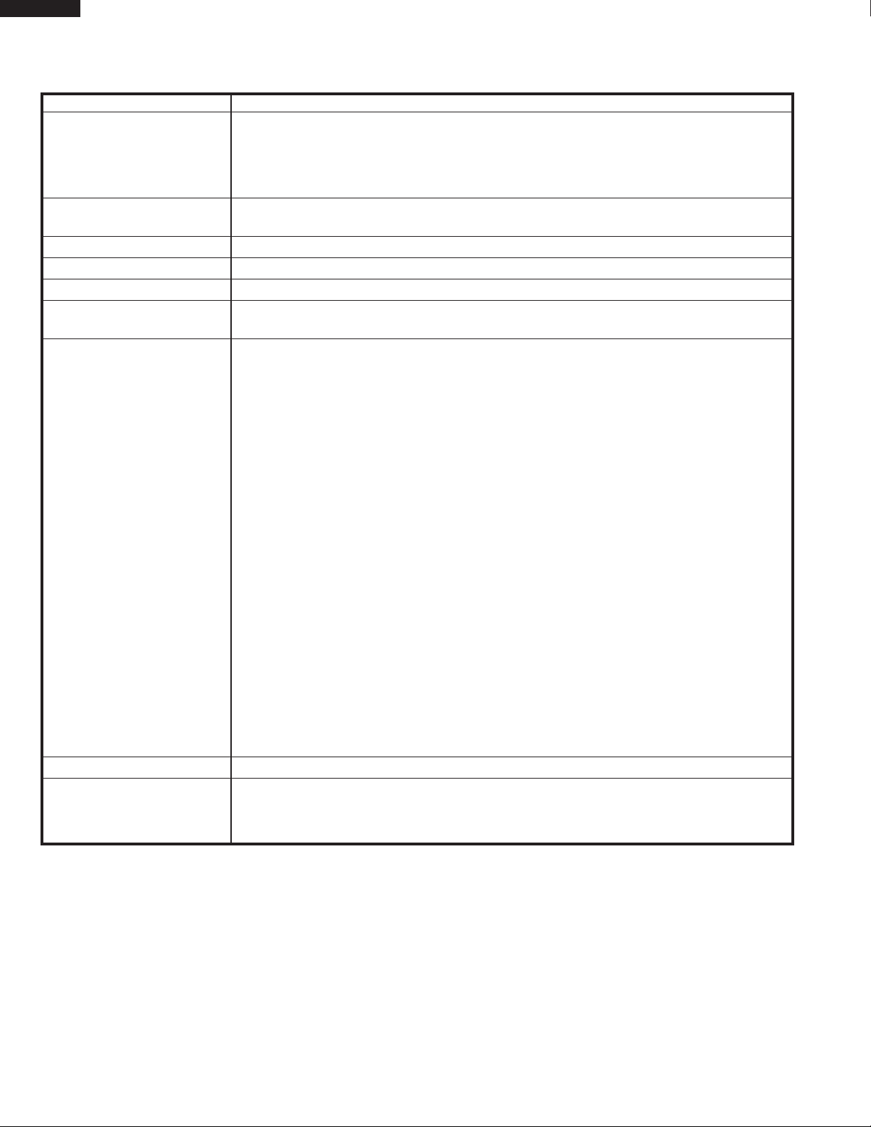
SPECIFICATION
ITEM DESCRIPTION
Power Requirements 240 Volts
7.9 Amperes (Microwave) / 14.2 Amperes (Convection)/ 12.8 Amperes (Speed
Cooking)
60 Hertz / Single phase, 3 wire grounded
Power Output 1000 watts (IEC Test Procedure)
Operating frequency of 2450MHz
Top Heater Power Output 1500 Watts
Side Heater Power Output 1200 Watts
Case Dimensions Width 30" Height 22-7/8" Depth 25-11/16"
Cooking Cavity Dimensions
(1.1 Cubic Feet ) Width 16-1/8" Height 8-3/8" Depth 13-5/8
Control Complement Touch Control System
Timer (0 - 99 min. 99 seconds)
Microwave Power for Variable Cooking
Repetition Rate;
HIGH POWER .......................................... Full power throughout the cooking time
90 PERCENT .............................................................. approx. 90% of Full Power
80 PERCENT .............................................................. approx. 80% of Full Power
70 PERCENT .............................................................. approx. 70% of Full Power
60 PERCENT .............................................................. approx. 60% of Full Power
50 PERCENT .............................................................. approx. 50% of Full Power
40 PERCENT ............................................................... approx. 40% of Full Power
30 PERCENT .............................................................. approx. 30% of Full Power
20 PERCENT .............................................................. approx. 20% of Full Power
10 PERCENT ............................................................... approx. 10% of Full Power
0 PERCENT .............................................. No power throughout the cooking time
"
Convection Temperature for Variable Cooking
CONVECTION ..............................................................100 - 450οF Temp. control
CUSTOM HELP pad, Add a Minute pad, SPEED GRILL pad, SPEED ROAST pad
SPEED BAKE pad, PREHEAT pad, CONVECTION pad, REHEAT pad, POPCORN pad
COOK pad, DEFROST pad, BASIC COOK pad, RECIPES pad
UP / DOWN pads, ENTER pad, Number and temperature selection pads,
TIMER / CLOCK pad, STOP/CLEAR pad, POWER LEVEL pad, START pad, Automatic cooking.
Oven Cavity Light Yes
Safety Standard UL Listed FCC Authorized
DHHS Rules, CFR, Title 21, Chapter 1, Subchapter J
Canadian Standards Association.
GENERAL INFORMATION
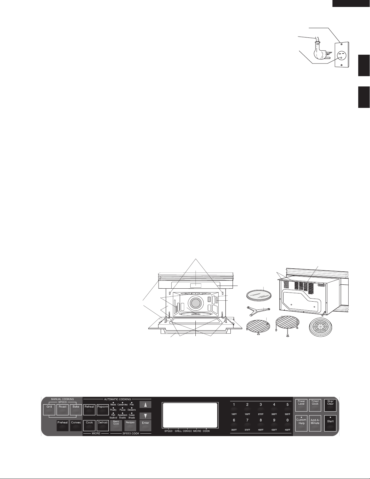
GROUNDING INSTRUCTIONS
This appliance must be grounded. This oven is equipped with a cord having a grounding wire with a grounding plug. It
must be plugged into a wall receptacle that is properly installed and grounded in accordance with the National Electrical
Code and local codes and ordinances. In the event of an electrical short circuit, grounding reduces risk of electric shock
by providing an escape wire for the electric current.
WARNING – Improper use of the grounding plug can result in a risk of electric shock.
6
VHSO205SS
Receptacle Box Cover
3 Pronged Plug
(6-15P)
3 Pronged Receptacle
(6-15R)
3
5
4
1
3
6
2
12
13
11
10
14
19
15
17
16
8
7
18
9
Electrical Requirements
The electrical requirements are a 240 volt 60 Hz, AC only, 15 amp. protected electrical
supply. It is recommended that a separate circuit serving only this appliance be provided.
The 240 volt circuit is absolutely necessary for optimum cooking performance. The oven
is equipped with a 3-prong grounding plug. It must be plugged into a wall receptacle
that is properly installed and grounded.
Extension Cord
If it is necessary to use an extension cord, use only a 3-wire extension cord that has a 3-blade grounding plug and a 3-slot
receptacle that will accept the plug on the high speed oven. The marked rating of the extension cord should be AC 240
volt, 15 amp. or more. Be careful not to drape the cord over the countertop or table where it can be pulled on by children
or tripped over accidentally.
CAUTION: DO NOT UNDER ANY CIRCUMSTANCES CUT OR REMOVE THE ROUND GROUNDING PRONG FROM
THIS PLUG.
1 Door handle
To open the door, pull the handle down and forward. Never hold the door handle when moving the oven.
2 Oven door with see-through window
3 Safety door latches
The oven will not operate unless the door is securely closed.
4 Door hinges
5 Door seals and sealing surfaces
6 Turntable motor shaft
7 Removable turntable support
Carefully place the turntable support in the center of the oven fl oor. After cooking, always clean the turntable support,
especially around the rollers. These must be free from food splashes and grease. Built-up splashes or grease may
overheat and cause arcing, begin to smoke or catch fi re.
8 Removable turntable
Place the turntable on the turntable support securely. The turntable will rotate clockwise or counterclockwise. Only
remove for cleaning.
9 Ventilation openings
10 Oven light
It will light when oven is operating or
door is open.
11 Wav e g ui de co v er : DO NOT
REMOVE.
12 Auto-Touch control panel
13 Time d i s p l ay: 99 m i n u t e s, 9 9
seconds
14 Convection air openings
15 Removable low rack
16 Removable high rack
17 Splash guard
18 Ve n ti l a t i o n c ov e r : D O N O T
OVEN DIAGRAM
TOUCH CONTROL PANEL
7

VHSO205SS
OPERATION
DESCRIPTION OF OPERATING SEQUENCE
The following is a description of component functions during oven operation.
OFF CONDITION
Closing the door activates the door sensing switch and
secondary interlock switch. (In this condition, the monitor
switch contacts are opened.)
When oven is plugged in, 240 volts A.C. is supplied to the
control unit. (Figure O-1).
1. The display will show "WELCOME TOUCH CLEAR AND
TOUCH CLOCK".
To set any program or set the clock, you must first touch
the STOP/CLEAR pad. The display will clear, and " : "
will appear.
NOTE: When the door is opened, the oven lamp comes
on.
2. A signal is input to the control unit, energizing the coil
of shut-off relay (RY-4). RY4 contacts close, completing
a circuit to the damper motor. The damper motor now
operates moving the damper to the open position, thereby
closing the contacts of the damper switch inputs a signal
to the control unit. The coil of relay RY-4 is de-energized,
opening its contacts, thereby turning off the damper
motor.
MICROWAVE COOKING CONDITION
Program desired cooking time Variable Cooking Control
by touching the NUMBER pads and the power level pad.
When the START pad is touched, the following operations
occur:
1. The contacts of relays are closed and components
connected to the relays are turned on as follows.
(For details, refer to Figure O-2)
RELAY CONNECTED COMPONENTS
RY-1 Oven lamp/Turntable motor
RY-2 Power transformer
RY-3 Convection motor
RY-4 Damper motor
RY-5 Fan motor
RY-6 Convection motor
2. 240 volts A.C. is supplied to the primary winding of the
power transformer and is converted to about 3.3 volts
A.C. output on the filament winding, and approximately
2300 volts A.C. on the high voltage winding.
3. The filament winding voltage heats the magnetron
filament and the H.V. winding voltage is sent to a voltage
doubler circuit.
4. The microwave energy produced by the magnetron is
channelled through the waveguide into the cavity feedbox, and then into the cavity where the food is placed
to be cooked.
5. Upon completion of the cooking time, the power
transformer, oven lamp, etc. are turned off, and the
generation of microwave energy is stopped. The oven
will revert to the OFF condition.
6. When the door is opened during a cook cycle, monitor
switch, door sensing switch, relay (RY1), the primary
interlock relay (RY2) and the secondary interlock switch
are activated with the following results. The circuits to
the turntable motor, the cooling fan motor, and the high
voltage components are de-energized, the oven lamp
remains on, and the digital read-out displays the time
still remaining in the cook cycle when the door was
opened.
7. The monitor switch is electrically monitoring the operation
of the primary interlock relay (RY2) and the secondary
interlock switch and is mechanically associated with the
door so that it will function in the following sequence.
(1) When the door opens from a closed position, the primary
interlock relay (RY2) and the secondary interlock switch
open their contacts. And contacts of the relay (RY1)
remain closed. Then the monitor switch contacts close.
(2) When the door is closed from the open position, the
monitor switch contacts first open, and then the contacts
of the secondary interlock switch close. And contacts of
the relay (RY1) open.
If the primary interlock relay (RY2) and the secondary interlock switch fail with their contacts closed when the door
is opened, the closing of the monitor switch contacts will
form a short circuit through the monitor fuse, relay (RY1),
primary interlock relay (RY2) and the secondary interlock
switch, causing the monitor fuse to blow.
POWER LEVEL P-0 TO P-90 COOKING
When Variable Cooking Power is programmed, the 240
volts A.C. is supplied to the power transformer intermittently
through the contacts of relay (RY-2). RY-2 is operated by the
control unit within an varying time base. Microwave power
operation is as follows:
VARI-MODE ON TIME OFF TIME
HIGH POWER (100% power) 32 sec. 0 sec.
90 PERCENT (approx. 90% power) 30 sec. 2 sec.
80 PERCENT (approx. 80% power) 26 sec. 6 sec.
70 PERCENT (approx. 70% power) 24 sec. 8 sec.
60 PERCENT (approx. 60% power) 22 sec. 10 sec.
50 PERCENT (approx. 50% power) 18 sec. 14 sec.
40 PERCENT (approx. 40% power) 16 sec. 16 sec.
30 PERCENT (approx. 30% power) 12 sec. 20 sec.
20 PERCENT (approx. 20% power) 8 sec. 24 sec.
10 PERCENT (approx. 10% power) 6 sec. 26 sec.
0 PERCENT (0% power) 0 sec. 32 sec.
Note: The ON/OFF time ratio does not correspond with the
percentage of microwave power, because approx. 3
seconds are needed for heating of the magnetron
filament.
CONVECTION COOKING CONDITION
PREHEATING CONDITION
Program desired convection temperature by touching the
PREHEAT pad and the Temperature pad. When the START
pad is touched, the following operations occur:
O-3)
(Figure
8

VHSO205SS
1. The coil of shut-off relays (RY1, RY3 and RY5) are
energized, the oven lamp, cooling fan motor, turntable
motor and convection motor are turned on.
2. The coil of relay (RY4) is energized by the control unit.
The damper is moved to the closed position, closing
the damper switch contacts. The closing of the damper
switch contacts sends a signal to the LSI on the control
unit de-energizing the relay (RY4) and opening the circuit
to the damper motor.
3. The solid-state relays are energized by the control unit
and the main supply voltage is applied to the top and
side heating elements.
4. When the oven temperature reaches the selected preheat
temperature, the following operations occur:
4-1 The solid-state relays are de-energized by the control
unit temperature circuit and thermistor, opening the
circuit to the heating elements.
4-2. The oven will continue to function for 30 minutes,
turning the heating elements on and off, as needed
to maintain the selected preheat temperature. The
oven will shutdown completely after 30 minutes
CONVECTION COOKING CONDITION
Touch the CONVECTION pad first and then touch the Temperature pad. And program desired cooking time by touching
the Number pads. When the START pad is touched, the
following operations occur: (Figure O-3)
1. The numbers on the digital read-out start to count down
to zero.
2. The oven lamp, turntable motor, cooling fan motor and
convection motor are energized.
3. The damper is moved to the closed position.
4. The solid-state relays are energized (if the cavity
temperature is lower than the selected temperature) and
the main supply voltage is applied to the heating elements
to return to the selected cooking temperature.
5. Upon completion of the cooking time, the audible signal
will sound, and oven lamp, turntable motor, cooling fan
motor and convection motor are de-energized. At the
end of the convection cycle, if the cavity air temperature
is above 230οF, the circuit to RY5 will be maintained (by
the thermistor circuit) to continue operation of the cooling
fan motor until the temperature drops below 195οF, at
which time the relay will be de-energized, turning off the
fan motor. Relay RY3 will however, open as soon as the
convection cycle has ended, turning off the convection
fan motor.
6. At the end of the convection cook cycle, if the cavity
air temperature is below 250
energized turning on the damper motor. The damper
is returned to the open position, closing the damper
switch contacts which send a signal to the control unit,
de-energizing shut-off relay (RY4).
NOTE: When "Preheat" and "Convection" is programmed
continuously, after preheat, the heating elements
operate as follows.
When one of 100οF to 375οF is selected, for the
first 1 minute, the top and side heating elements
are not energized. When one of 400οF to 450οF
is selected, for the first 2 minutes, the top and
side heating elements are not energized.
ο
F, shut-off relay (RY4) is
SPEED BAKE COOKING
Touch the BAKE pad and then enter cooking time. When the
start pad is touched, following operations occur;
(Figure O-3)
1. The contacts of the relays RY1, RY3 and RY5 are closed,
and the oven lamp, turntable motor, convection motor
and fan motors are energized.
NOTE : The rotate direction of the convection motor is
the same as one of the convection cooking.
2. The damper is moved to the closed position.
3. The solid-state relays are energized and the main
supply voltage is applied to the top and side heating
elements.
NOTE : After cooking, the operation of the fan motors,
damper motor is the same as one of the
convection cooking.
SPEED GRILL COOKING
Touch the GRILL pad and then enter cooking time. When
the start pad is touched, following operations occur;
(Figure O-4)
1. The contacts of the relays RY1, RY3, RY5 and RY6 are
closed, and the oven lamp, turntable motor, convection
motor and fan motors are energized.
NOTE : The rotate direction of the convection motor is
reverse to one of the convection cooking by the
relay RY6.
2. The damper is moved to the closed position.
3. The solid-state relays are energized and the main
supply voltage is applied to the top and side heating
elements.
NOTE : After cooking, the operation of the fan motors,
damper motor is the same as one of the
convection cooking.
SPEED ROAST COOKING
Touch the ROAST pad and then enter cooking time. When
the start pad is touched, following operations occur;
(Figure O-5)
1. The contacts of the relays RY1, RY3 and RY5 are closed,
and the oven lamp, turntable motor, convection motor
and fan motors are energized.
NOTE : The rotate direction of the convection motor is
the same as one of the convection cooking for
the first time. But for the last 15 minutes, the
direction is reverse by the relay RY6.
2. The damper is moved to the closed position.
3. The solid-state relays and relay RY2 are energized
alternately, and the main supply voltage is applied to the
top and side heating elements and the power transformer
alternately.
NOTE : After cooking, the operation of the fan motors,
damper motor is the same as one of the
convection cooking.
SPEED COOKING OF AUTOMATIC COOKING
(BASIC COOK, RECIPES)
Speed cooking of Automatic cooking will automatically
compute the oven temperature, microwave power and cooking time. And the oven will cook according to the special
cooking sequence.
MICROWAVE OPTIONS OF AUTOMATIC COOKING
9
VHSO205SS
CONVECTION
MOTOR
THERMISTOR
Sensing
Voltage
ON
OFF
ON
OFF
ON
OFF
0 2 3 28 31 32 (sec.) 64 (sec.)
3 sec.
Sensing the voltage across temperature measurement circuit.
3 sec.
NOTES:
1. Circuits / Wire Colors subject to change without notice.
LV TRANSFORMER
C2
C1
C4
C3
A2
A1
A3
A6
A8
D9
RY2
RY1
RY5
RY4
RY3
RY6
RECTIFIER
SOLID-STATE RELAY
INTERLOCK RELAY
PRIMARY
SECONDARY
INTERLOCK
SWITCH
FAN MOTOR
UNIT
CONTROL
MONITOR SWITCH
1.0 uF
CAPACITOR
AC 2300V
MAGNETRON
RED
BLK
DAMPER
SWITCH
SWITCH
DOOR
SENSING
JET MOTOR
TURNTABLE MOTOR
N.O.
N.O.
JM
DM
FM
FM
OL
TTM
THERMISTOR
SOLID-STATE RELAY
SIDE HEATER
TOP HEATER
COM.
COM.
DAMPER MOTOR
B3
B4
B1
B2
B6
D7
D5
D3
E3
E5
E1
SIDE HEATER
CUT-OUT
THERMAL
CUT-OUT
TOP HEATER
THERMAL
MG.
FUSE
TEMP.
OVEN LAMP
F10A
FUSE
D1
WITH 150°C THERMOSTAT
TRANSFORMER
POWER
IN PRIMARY WINDING
GND
240V 60Hz
RED
GRY
RED
BLK
BLK
RED
BRN
BLK
RED
BRN
BLK
RED
RED
BLK
ORG
BRN
ORG
BRN
RED
BLK
ORG
BLK
ORG
BLK
ORG
RED
RED
RED
ORG
ORG
ORG
BLK
RED
GRY
WHT
GRY
BLK
GRY
GRY
GRY
WHT
GRY
WHT
GRY
GRY
WHT
GRY
WHT
GRY
WHT
WHT
RED
BLU
GRY
WHT
WHT
GRY
N.O.
COM.
GRY
BLK
GRN
RED
BRN
YLW
BLU
ORG
BLU
RED
G
R
N
BLK
BRN
GRN
WHT
GRN
GRN
WHT
WHT
A4
FUSE1
2.5A
BLK
WHT
L
L
NOISE SUPRESSION COIL
LINE CROSS CAPACITOR 1.0 uF 275V
RESISTOR 680 kOHM 1/2W
RESISTOR 10 MOHM 1/2W
LINE BYPASS CAPACITOR
0.0033 uF 250V
LINE BYP
ASS CAP
ACITOR
0.0033 uF 250V
FUSE
20A
(REHEAT, POPCORN, COOK, DEFROST)
Microwave options of Automatic cooking will automatically
compute the microwave power, cooking time or defrosting
time. And the oven will cook according to the special cooking sequence.
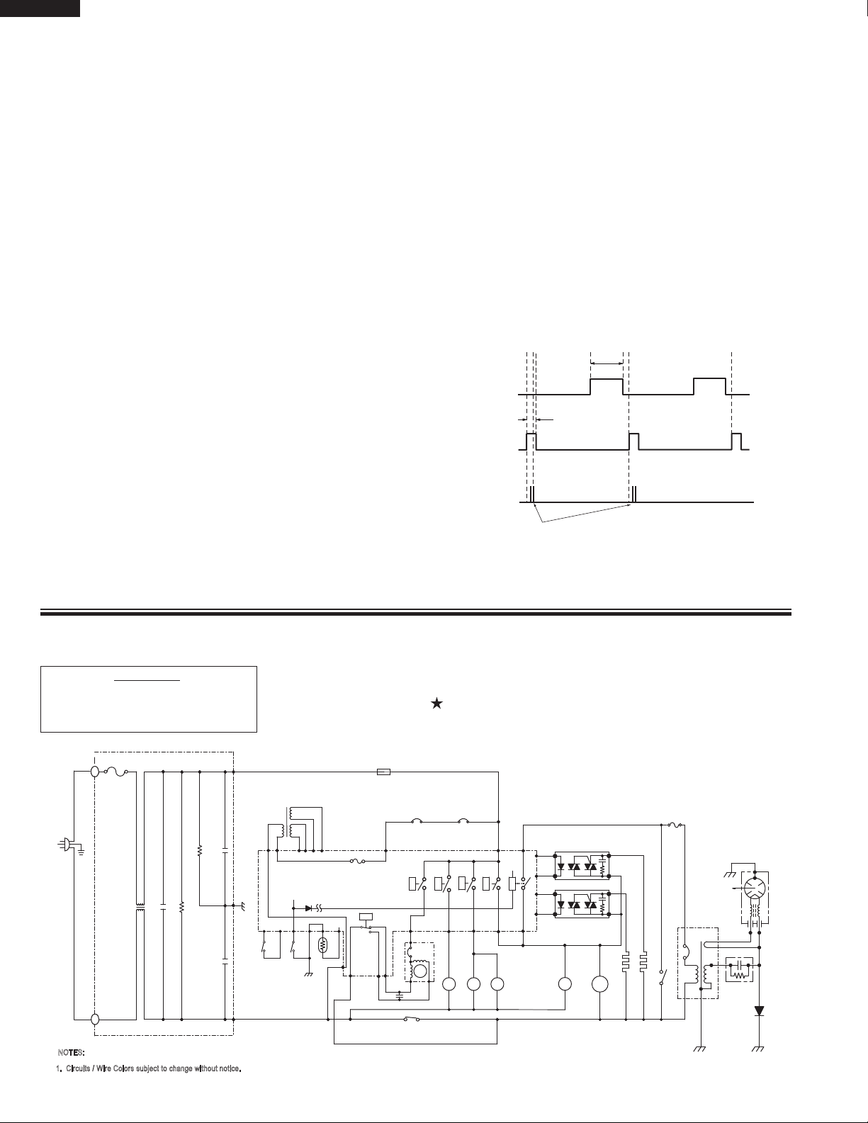
FIRE SENSING FEATURE (MICROWAVE MODE)
This model incorporates a sensing feature which will stop
the oven's operation if there is a fire in the oven cavity
during microwave cooking. This fire sensing feature will
operate when the microwave power level is set to 80% or
more. This is accomplished by the LSI repeatedly measuring the voltage across the temperature measurement circuit
(thermistor) during it's 32-seconds time base comparing the
obtained voltage measurements. If the most recent voltage measured is 300 mV greater than the previous voltage
measured, the LSI judges it as a fire in the oven cavity and
switches off the relays to the power transformer, fan motor
and convection motor. The LSI also stops counting down
and closes the damper door so that no fresh air will enter
the oven cavity. Please refer to the following section for a
more detailed description.
Operation
Please refer to the timing diagrams below.
1. The fire sensing will start after 30 minutes when the oven
is started.
2. The thermistor operates within a 32-seconds time
base and it is energized for three (3) seconds and off
for 29 seconds. Two (2) seconds after the thermistor
is energized, the voltage across the temperature
measurement circuit is sampled by the LSI and twenty
five (25) seconds after the thermistor is cut off the LSI
turns on the convection fan for three (3) seconds.
3. The above procedure is repeated. If the difference
between the first voltage measured (in step 1) and the
voltage measured when the procedure is repeated (step
2) is greater than 300 mV the LSI makes the judgment
that there is a fire in the oven cavity and will switch
off the relays to the power transformer, fan motor and
convection motor. The LSI also stops counting down and
closes the damper door so that no fresh air will enter the
oven cavity.
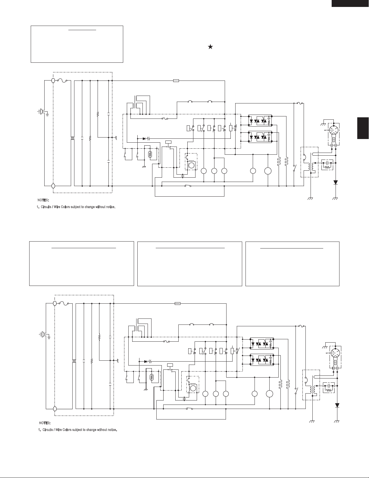
NOTE: CONDITION OF OVEN
SCHEMATIC
1. DOOR CLOSED.
2. CLOCK APPEARS ON DISPLAY.
SCHEMATIC DIAGRAM
NOTE: "
Figure O-1. Oven Schematic-OFF Condition
" indicates components with potential above 250V.
10
VHSO205SS
NOTES:
1. Circuits / Wire Colors subject to change without notice.
LV TRANSFORMER
C2
C1
C4
C3
A2
A1
A3
A6
A8
D9
RY2
RY1
RY5
RY4
RY3
RY6
RECTIFIER
SOLID-STATE RELAY
INTERLOCK RELAY
PRIMARY
SECONDARY
INTERLOCK
SWITCH
FAN MOTOR
UNIT
CONTROL
MONITOR SWITCH
1.0 uF
CAPACITOR
AC 2300V
MAGNETRON
RED
BLK
DAMPER
SWITCH
SWITCH
DOOR
SENSING
JET MOTOR
TURNTABLE MOTOR
N.O.
N.O.
JM
DM
FM
FM
OL
TTM
THERMISTOR
SOLID-STATE RELAY
SIDE HEATER
TOP HEATER
COM.
COM.
DAMPER MOTOR
B3
B4
B1
B2
B6
D7
D5
D3
E3
E5
E1
SIDE HEATER
CUT-OUT
THERMAL
CUT-OUT
TOP HEATER
THERMAL
MG.
FUSE
TEMP.
OVEN LAMP
F10A
FUSE
D1
WITH 150°C THERMOSTAT
TRANSFORMER
POWER
IN PRIMARY WINDING
GND
240V 60Hz
RED
GRY
RED
BLK
BLK
RED
BRN
BLK
RED
BRN
BLK
RED
RED
BLK
ORG
BRN
ORG
BRN
RED
BLK
ORG
BLK
ORG
BLK
ORG
RED
RED
RED
ORG
ORG
ORG
BLK
RED
GRY
WHT
GRY
BLK
GRY
GRY
GRY
WHT
GRY
WHT
GRY
GRY
WHT
GRY
WHT
GRY
WHT
WHT
RED
BLU
GRY
WHT
WHT
GRY
N.O.
COM.
GRY
BLK
GRN
RED
BRN
YLW
BLU
ORG
BLU
RED
G
R
N
BLK
BRN
GRN
WHT
GRN
GRN
WHT
WHT
A4
FUSE1
2.5A
BLK
WHT
L
L
NOISE SUPRESSION COIL
LINE CROSS CAPACITOR 1.0 uF 275V
RESISTOR 680 kOHM 1/2W
RESISTOR 10 MOHM 1/2W
LINE BYPASS CAPACITOR
0.0033 uF 250V
LINE BYP
ASS CAP
ACITOR
0.0033 uF 250V
FUSE
20A
NOTE: CONDITION OF OVEN
SCHEMATIC
1. DOOR CLOSED.
2. COOKING TIME PROGRAMMED.
3. “START” PAD TOUCHED.
NOTE: "
" indicates components with potential above 250V.
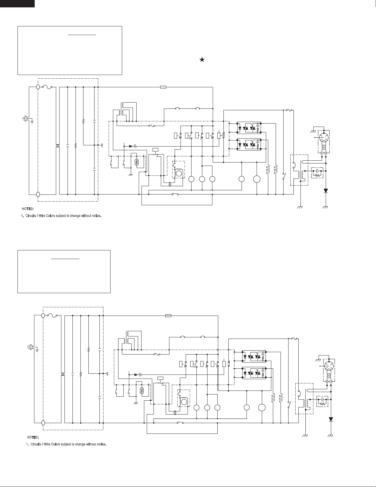
SCHEMATIC (CONVECTION)
NOTE: CONDITION OF OVEN
1. DOOR CLOSED.
2. CONVECTION PAD TOUCHED.
3. DESIRED TEMPERATURE SELECTED.
4. COOKING TIME PROGRAMMED.
5. “START” PAD TOUCHED.
Figure O-3. Oven Schematic-Convection, Reheat, Speed Bake Cooking Condition
Figure O-2. Oven Schematic-Microwave Cooking Condition
SCHEMATIC (SPEED REHEAT)
NOTE: CONDITION OF OVEN
1. DOOR CLOSED.
2. REHEAT PAD TOUCHED.
3. DESIRED TEMPERATURE SELECTED.
4. COOKING TIME PROGRAMMED.
5. “START” PAD TOUCHED.
SCHEMATIC (SPED BAKED)
NOTE: CONDITION OF OVEN
1. DOOR CLOSED.
2. BAKED PAD TOUCHED.
3. COOKING TIME PROGRAMMED.
4. “START” PAD TOUCHED.
11
VHSO205SS
NOTES:
1. Circuits / Wire Colors subject to change without notice.
LV TRANSFORMER
C2
C1
C4
C3
A2
A1
A3
A6
A8
D9
RY2
RY1
RY5
RY4
RY3
RY6
RECTIFIER
SOLID-STATE RELAY
INTERLOCK RELAY
PRIMARY
SECONDARY
INTERLOCK
SWITCH
FAN MOTOR
UNIT
CONTROL
MONITOR SWITCH
1.0 uF
CAPACITOR
AC 2300V
MAGNETRON
RED
BLK
DAMPER
SWITCH
SWITCH
DOOR
SENSING
JET MOTOR
TURNTABLE MOTOR
N.O.
N.O.
JM
DM
FM
FM
OL
TTM
THERMISTOR
SOLID-STATE RELAY
SIDE HEATER
TOP HEATER
COM.
COM.
DAMPER MOTOR
B3
B4
B1
B2
B6
D7
D5
D3
E3
E5
E1
SIDE HEATER
CUT-OUT
THERMAL
CUT-OUT
TOP HEATER
THERMAL
MG.
FUSE
TEMP.
OVEN LAMP
F10A
FUSE
D1
WITH 150°C THERMOSTAT
TRANSFORMER
POWER
IN PRIMARY WINDING
GND
240V 60Hz
RED
GRY
RED
BLK
BLK
RED
BRN
BLK
RED
BRN
BLK
RED
RED
BLK
ORG
BRN
ORG
BRN
RED
BLK
ORG
BLK
ORG
BLK
ORG
RED
RED
RED
ORG
ORG
ORG
BLK
RED
GRY
WHT
GRY
BLK
GRY
GRY
GRY
WHT
GRY
WHT
GRY
GRY
WHT
GRY
WHT
GRY
WHT
WHT
RED
BLU
GRY
WHT
WHT
GRY
N.O.
COM.
GRY
BLK
GRN
RED
BRN
YLW
BLU
ORG
BLU
RED
G
R
N
BLK
BRN
GRN
WHT
GRN
GRN
WHT
WHT
A4
FUSE1
2.5A
BLK
WHT
L
L
NOISE SUPRESSION COIL
LINE CROSS CAPACITOR 1.0 uF 275V
RESISTOR 680 kOHM 1/2W
RESISTOR 10 MOHM 1/2W
LINE BYPASS CAPACITOR
0.0033 uF 250V
LINE BYP
ASS CAP
ACITOR
0.0033 uF 250V
FUSE
20A
NOTES:
1. Circuits / Wire Colors subject to change without notice.
LV TRANSFORMER
C2
C1
C4
C3
A2
A1
A3
A6
A8
D9
RY2
RY1
RY5
RY4
RY3
RY6
RECTIFIER
SOLID-STATE RELAY
INTERLOCK RELAY
PRIMARY
SECONDARY
INTERLOCK
SWITCH
FAN MOTOR
UNIT
CONTROL
MONITOR SWITCH
1.0 uF
CAPACITOR
AC 2300V
MAGNETRON
RED
BLK
DAMPER
SWITCH
SWITCH
DOOR
SENSING
JET MOTOR
TURNTABLE MOTOR
N.O.
N.O.
JM
DM
FM
FM
OL
TTM
THERMISTOR
SOLID-STATE RELAY
SIDE HEATER
TOP HEATER
COM.
COM.
DAMPER MOTOR
B3
B4
B1
B2
B6
D7
D5
D3
E3
E5
E1
SIDE HEATER
CUT-OUT
THERMAL
CUT-OUT
TOP HEATER
THERMAL
MG.
FUSE
TEMP.
OVEN LAMP
F10A
FUSE
D1
WITH 150°C THERMOSTAT
TRANSFORMER
POWER
IN PRIMARY WINDING
GND
240V 60Hz
RED
GRY
RED
BLK
BLK
RED
BRN
BLK
RED
BRN
BLK
RED
RED
BLK
ORG
BRN
ORG
BRN
RED
BLK
ORG
BLK
ORG
BLK
ORG
RED
RED
RED
ORG
ORG
ORG
BLK
RED
GRY
WHT
GRY
BLK
GRY
GRY
GRY
WHT
GRY
WHT
GRY
GRY
WHT
GRY
WHT
GRY
WHT
WHT
RED
BLU
GRY
WHT
WHT
GRY
N.O.
COM.
GRY
BLK
GRN
RED
BRN
YLW
BLU
ORG
BLU
RED
G
R
N
BLK
BRN
GRN
WHT
GRN
GRN
WHT
WHT
A4
FUSE1
2.5A
BLK
WHT
L
L
NOISE SUPRESSION COIL
LINE CROSS CAPACITOR 1.0 uF 275V
RESISTOR 680 kOHM 1/2W
RESISTOR 10 MOHM 1/2W
LINE BYPASS CAPACITOR
0.0033 uF 250V
LINE BYP
ASS CAP
ACITOR
0.0033 uF 250V
FUSE
20A
NOTE: CONDITION OF OVEN
SCHEMATIC
1. DOOR CLOSED.
2. GRILL PAD TOUCHED.
3. COOKING TIME PROGRAMMED.
4. “START” PAD TOUCHED.
NOTE: " " indicates components with potential above 250V.
NOTE: CONDITION OF OVEN
SCHEMATIC
1. DOOR CLOSED.
2. ROAST PAD TOUCHED.
3. COOKING TIME PROGRAMMED.
4. “START” PAD TOUCHED.
Figure O-4. Oven Schematic-Speed Grill Cooking Condition
NOTE: The solid-state relays and relay RY2 are energized alternately.
For last 15 minutes, the contacts of relay RY6 will contact D5.
Figure O-5. Oven Schematic-Speed Roast Cooking Condition
12
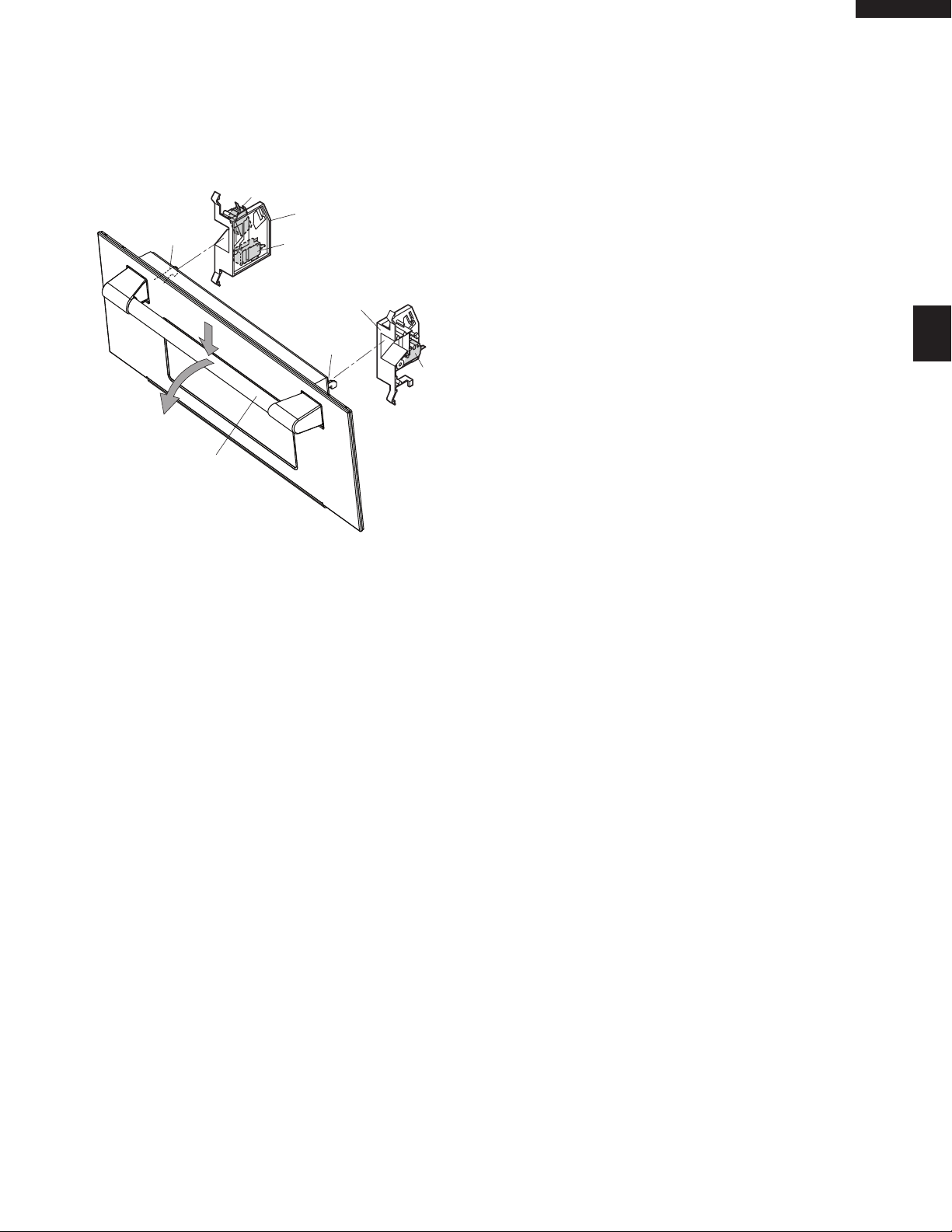
Monitor switch
Latch hook left
Door handle
Latch
head
Secondary
interlock switch
Door
sensing switch
Latch hook right
Latch
head
DESCRIPTION AND FUNCTION OF COMPONENTS
DOOR OPEN MECHANISM
The door is opened by pulling the door handle down and
forward, referring to the figure D-1. When the door handle is
pulled down, the latch heads are moved upward. And then
when the door handle is pulled forward, the latch heads
are released from the latch hooks right and left. Now, the
door will open.
Figure D-1. Door Open Mechanism
DOOR SENSING AND SECONDARY INTERLOCK
SWITCHES
The door sensing switch in the primary interlock system is
mounted in the lower position on the latch hook right, the
secondary interlock switch is mounted in the lower position
on the latch hook left. They are activated by the latch heads
on the door. When the door is opened, the switches interrupt
the circuit to all components except for the oven lamp. A
cook cycle cannot take place until the door is firmly closed
thereby activating both interlock switches. The primary interlock system consists of the door sensing switch and primary
interlock relay located on the control circuit board.
MONITOR SWITCH
The monitor switch is mounted on the upper position of latch
hook left. It is activated (the contacts opened) by the left
latch head while the door is closed. The switch is intended
to render the oven inoperative by means of blowing the
monitor fuse when the contacts of the primary interlock
relay and secondary interlock switch fail to open when the
door is opened.
Functions:
1. When the door is opened, the monitor switch contact close
(to the ON condition) due to their being normally closed.
At this time the door sensing and secondary interlock
switches are in the OFF condition (contacts open) due
to their being normally open contact switches.
2. As the door goes to a closed position, the monitor switch
contacts are first opened and then the door sensing
switch and the secondary interlock switch contacts close.
(On opening the door, each of these switches operate
inversely.)
3. If the door is opened, and the primary interlock relay
and secondary interlock switch contacts fail to open, the
monitor fuse blows simultaneously with closing of the
monitor switch contacts.
CAUTION: BEFORE REPLACING A BLOWN MONITOR
FUSE TEST THE DOOR SENSING SWITCH,
PRIMARY INTERLOCK RELAY, SECOND
ARY INTERLOCK SWITCH AND MONITOR
SWITCH FOR PROPER OPERATION. (REFER
TO CHAPTER “TEST PROCEDURE”).
NOTE: MONITOR FUSE AND MONITOR SWITCH ARE
REPLACED AS AN ASSEMBLY.
THERMISTOR
The thermistor is a negative temperature coefficient type.
The temperature in the oven cavity is detected through the
resistance of the thermistor, and then the control unit causes
the heater relay to operate, thus the current to the heating
elements is turned ON/OFF. If the convection cooking or some
cooking modes which use the top / side heating elements
is started and the oven temperature does not rise above
100οF (37.8οC), the control unit will stop the oven after 10
minutes. In this case, the thermistor may be opened.
MAGNETRON TEMPERATURE FUSE.
The temperature fuse located on the waveguide flange is
designed to prevent damage to the magnetron if an over
heated condition develops in the magnetron due to cooling
fan failure, obstructed air guide, dirty or blocked air intake,
etc.
Under normal operation, the temperature fuse remains
closed. However, when abnormally high temperatures are
reached within the magnetron, the temperature fuse will
remain open at 302οF(150οC) causing the oven to shut
down.
TOP HEATER THERMAL CUT-OUT
The thermal cut-out located on the thermal cover upper is
designed to prevent damage to the top heating element
unit if an over heated condition develops in the top heating
element unit due to convection fan failure, thermistor failure,
obstructed air ducts, dirty or blocked air intake, etc.
Under normal operation, the thermal cut-out remains closed.
However, when abnormally high temperature are reached
within the top heating element unit, the thermal cut-out
will open at 338οF (170οC) causing the oven to shut down.
When the thermal cut-out has cooled, the thermal cut-out
closes at 311οF(155οC).
SIDE HEATER THERMAL CUT-OUT
The thermal cut-out located on the thermal cover left is
designed to prevent damage to the side heating element
unit if an over heated condition develops in the top heating
element unit due to convection fan failure, thermistor failure,
obstructed air ducts, dirty or blocked air intake, etc.
Under normal operation, the thermal cut-out remains closed.
However, when abnormally high temperature are reached
within the side heating element unit, the thermal cut-out
VHSO205SS
-
13
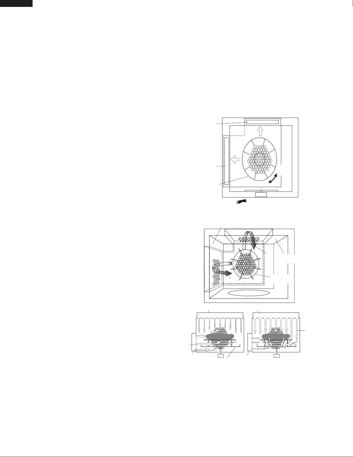
VHSO205SS
Side heating
element unit
Top heating
element unit
Convection
fan
Convection mode
JET
mode
FRONT VIEW
Hot air
Hot air
Hot air
Convection
fan
Hot air
Oven cavity left side
Oven cavity
top wall
Side heating
element unit
Side heating
element unit
Top heating element unit Top heating element unit
Turntable
Convection Mode JET Mode
will open at 302οF (150οC) causing the oven to shut down.
When the thermal cut-out has cooled, the thermal cut-out
closes at 266οF (130οC).
TOP HEATING ELEMENT
The top heating element is located at the top of the oven
cavity. It is intended to heat air driven by the convection fan.
The heated air is kept in the oven and force-circulated and
reheated by the top heating element.
SIDE HEATING ELEMENT
The side heating element is located at the left side of the
oven cavity. It is intended to heat air driven by the convection
fan. The heated air is kept in the oven and force-circulated
and reheated by the top heating element.
TURNTABLE MOTOR
The turntable motor rotates the turntable located in the
bottom of the oven cavity, so that the food on the turntable
is cooked evenly during cooking. The turntable may turn in
either direction.
FAN MOTOR (MAGNETRON SIDE)
The fan motor drives a blade which draws external cool air.
This cool air is directed through the air vents surrounding the
magnetron and cools the magnetron. This air is channelled
through the oven cavity to remove steam and vapors given
off from the heating foods. It is then exhausted through the
exhausting air vents at the oven cavity.
selected temperature. When the convection time reaches 0,
the heating elements are de-energized and the convection
fan stops operating and the oven shuts off.
Flow of hot air:
The rotation direction of the convection motor is controlled
by relay RY6. When the convection fan rotates clockwise,
the hot air from the oven cavity left side wall blows stronger
than one from the oven cavity top wall. ( This mode is called
“Convection mode”.) When the convection fan rotates counterclockwise, the hot air from the oven cavity top wall blows
stronger than one from the oven cavity left side wall. (This
mode is called “JET mode”.)
Figure D-2. Rotation direction of convection fan
FAN MOTOR (POWER TRANSFORMER SIDE)
The fan motor drives a blade which draws external cool air.
This cool air is directed through the air vents surrounding the
power transformer and cools the power transformer. This air
is channelled through the oven cavity to remove steam and
vapors given off from the heating foods. It is then exhausted
through the exhausting air vents at the oven cavity.
CONVECTION COOKING SYSTEM
This oven is designed with a hot air heating system where
food is not directly heated by the heating element, but is
heated by forced circulation of the hot air produced by the
heating elements. The air heated by the heating elements is
circulated through the convection passage provided on the
outer casing of the oven cavity by means of the convection
fan which is driven by the convection motor. It then enters
the inside of the oven through the vent holes provided on
the top and left sides of the oven. Next, the hot air heats the
food on the turntable and leaves the oven cavity through the
vent in the center of the oven cavity back side wall. Without
leaving the oven, this hot air is reheated by the heating elements, passes through the convection passage and enters
the inside of the oven cavity again, in a continuing cycle.
In this way, the hot air circulates inside the oven cavity to
raise its temperature and, at the same time, comes into
contact with the food being cooked. When the temperature
inside the oven cavity reaches the selected temperature, the
heating elements are de-energized. When the temperature
inside the oven cavity drops below the selected temperature,
the heating elements are energized again. In this way, the
inside of the oven cavity is maintained at approximately the
Figure D-3. Flow of hot air
DAMPER OPEN-CLOSE MECHANISM
Usually, the damper is in the open position except during
convection cooking, reheat, speed grill, speed roast, speed
bake, or all cooking modes which use the top / side heating
elements. Damper position is set automatically by damper
motor, damper switch, motor cam and damper shaft. These
components are operated by a signal that judges if microwave cooking, convection cooking operation or other cooking
14

VHSO205SS
operation is selected by the control unit.
Microwave Cooking:
Damper is in the open position, because a portion of cooling air is channelled through the cavity to remove steam
and vapors given off from the heating foods. It is then exhausted at the top of the oven cavity into a condensation
compartment.
Convection, Preheat, Speed Grill, Speed Roast, Speed
Bake, or all cooking modes which use the top / side
heating elements:
Damper is in the closed position, so that no hot air will be
allowed to leak out the oven cavity.
Damper Operation
1. When power supply cord is plugged in:
1-1. When power supply cord is plugged in, a signal is
sensed in the control unit, and operates shut-off
relay (RY4).
1-2. Contacts of shut-off relay (RY4) close, the damper
motor is energized, opening the damper door.
1-3. When the damper is moved to the open position by
the damper cam the damper switch is opened (OFF
position).
1-4. The signal from damper switch is re-sensed in the
control unit and shut-off relay (RY4) is turned off.
1-5. The 240 volts A.C. to the damper motor is removed
and the motor turns off.
2. When oven is microwave cooking:
Damper is in the open position.
3. When oven is convection cooking:
3-1. Damper motor is energized by touching the
convection, temperature and START pads.
3-2. When damper is in the closed position (damper
switch is ON), its signal is sensed by the control
unit, and shut-off relay (RY4) is de-energized.
3-3. The damper is held in the closed position during the
convection cooking operation.
3-4. At the end of the convection cooking, if the cavity air
temperature is below 250οF, shut-off relay (RY4) is
energized, and the damper is returned to the open
position.
NOTE: If the damper door is not in the proper position,
closed during convection or open during
microwave, the control unit will stop oven
TROUBLESHOOTING GUIDE
Never touch any part in the circuit with your hand or an uninsulated tool while the power supply is connected.
When troubleshooting the microwave oven, it is helpful to follow the Sequence of Operation in performing the checks. Many
of the possible causes of trouble will require that a specific test be performed. These tests are given a procedure letter
which will be found in the "Test Procedure "section.
IMPORTANT: If the oven becomes inoperative because of a blown monitor fuse, check the monitor switch, relay (RY1)
primary interlock relay (RY2), door sensing switch and secondary interlock switch before replacing the
monitor fuse. If the monitor fuse is replaced, the monitor switch must also be replaced. Use part FFSBA033WRKZ as an assembly.
IMPORTANT: Whenever troubleshooting is performed with the power supply cord disconnected. It may in, some cases,
be necessary to connect the power supply cord after the outer case has been removed, in this event,
1. Disconnect the power supply cord
2. Remove the outer case cabinet, referring to "OUTER CASE CABINET REMOVAL".
3. Open the door and block it open.
4. Discharge high voltage capacitor.
5. Remove the back plate from the oven, referring to "BACK PLATE REMOVAL".
6. Disconnect the leads to the primary of the power transformer.
7. Ensure that the leads remain isolated from other components and oven chassis by using insulation
tape.
8. After that procedure, reconnect the power supply cord.
When the testing is completed
1. Disconnect the power supply cord, and then remove outer case.
2. Open the door and block it open.
3. Discharge high voltage capacitor.
4. Reconnect all leads removed from components during testing.
5. Reinstall the outer case (cabinet) and theback plate.
15

VHSO205SS
CONDITION
PROBLEM
TEST PROCEDURE
POSSIBLE CAUSE
DEFECTIVE PARTS
A MAGNETRON
B POWER TRANSFORMER
C H.V. RECTIFIER ASSEMBLY
D HIGH VOLTAGE CAPACITOR
E SECONDARY INTERLOCK SWITCH
F PRIMARY INTERLOCK SYSTEM
G MONITOR SWITCH
H MONITOR FUSE
J MAGNETRON TEMPERATURE FUSE
K THERMAL CUT-OUT (TOP)
M TOP HEATING ELEMENT
O THERMISTOR
P DAMPER MOTOR
Q DAMPER SWITCH
U TOUCH CONTROL PANEL
V TACT SWITCH
W RELAY RY-1
W RELAY RY-2
W RELAY RY-3
W RELAY RY-4
W RELAY RY-5
W RELAY RY-6
Y DEFROST
Z FUSE1 ON PWB.
X SOLID-STATE RELAY (TOP)
X SOLID-STATE RELAY (SIDE)
Replace OVEN LAMP
Replace FAN MOTOR (MAGNETRON)
Replace TURNTABLE MOTOR
S CONVECTION MOTOR
Check LOOSE WIRING
Check SHORTED IN POWER CORD
Check NO POWER AT OUTLET
Check LOW VOLTAGE
L THERMAL CUT OUT (SIDE)
N SIDE HEATING ELEMENT
Replace
FAN MOTOR (POWER TRANSFORMER)
U LV TRANSFORMER
I FUSE F10A
R CONVECTION MOTOR CAPACITOR
AND
OFF CONDITION
Home fuse blows when power cord is plugged into wall receptacle.
Monitor fuse blows when power cord is plugged into wall receptacle
COOKING CONDITION (MICROWAVE)
Extremely uneven heating is produced in oven load (food).
Oven does not go into a cook cycle, when START pad is touched.
88:88 does not appear in display when power cord is first plugged into
Display does not operate properly when STOP/CLEAR pad is touched.
Oven lamp does not light with door opened.
Oven lamp does not light in cook cycle. (It light when door is opened).
Cooking cycle runs 1 minute then shuts down.
Oven lamp light, but turntable motor does not operate.
wall receptacle.
(The time of day should appear on the display with beep sound.)
Turntable motor operates normally but cooling fan motor does not
operate.
Low or no power is produced during microwave cooking (The food is
heated incompletely or not heated at all)
Function of variable cooking does not operate properly except HIGH
(CONVECTION, SPEED BAKE/
GRILL/ROAST)
Function of DEFROST does not operate properly.
power.
Oven does not go into cook cycle when START pad is touched.
Heating elements do not heat.
Temperature in the oven cavity is lower or higher than preset.
Convection cycle runs for 10 minutes then shuts down.
Convection motor does not operate of all or properly.
16
 Loading...