


Page 1
Viking Use/Installation Guide
Viking Range, LLC
111 Front Street
Greenwood, Mississippi 38930 USA
(662) 455-1200
For product information,
call 1-888-(845-4641)
or visit the Viking website at
vikingrange.com
F21363 EN
Outdoor 15” Wide Double Side Burners
(120913)
Page 2
Important: Please Read and Follow
1. Before beginning, please read these instructions completely and carefully.
2. Do not remove permanently affixed labels, warnings, or plates from product. This may void the warranty
3. Please observe all local and national codes and ordinances.
4. The installer should leave these instructions with the consumer who should retain for local inspector’s use and for
uture reference
f
nstallation must conform with local codes or in the absence of codes, the National Fuel Gas Code, ANSI Z223.1.
I
IInn CCaannaaddaa::
CAN/CGA-B149.2, Propane Installation Code and/or local codes.
Installation must be in accordance with the current CAN/CGA-B149.1, Natural Gas Installation Code or
Safety Tips
•Keep outdoor cooking appliance area free from combustible materials, gasoline and other flammable vapors and
liquids.
•Keep ventilation openings at the rear of the cart and cylinder free and clear to allow proper air flow. Do not obstruct
the flow of combustion and ventilation air.
•Spiders and insects can nest in the burners of the grill and block the gas and air flow to the burner ports. This may
cause a fire from behind the manifold cover. Inspect and clean burners periodically.
BBAASSIICC SSPPEECCIIFFIICCAATTIIOONNSS
DDeessccrriippttiioonn
VVGGSSBB55115533
FOR YOUR SAFETY
IIff yyoouu ssmmeellll ggaass::
11.. SShhuutt ooffff ggaass ttoo tthhee aapppplliiaannccee..
22.. EExxttiinngguuiisshh aannyy ooppeenn ffllaammee..
33.. OOppeenn lliidd..
44.. IIff ooddoorr ccoonnttiinnuueess,, iimmmmeeddiiaatteellyy ccaallll yyoouurr ggaass ssuupppplliieerr oorr yyoouurr
ffiirree ddeeppaarrttmmeenntt..
FOR YOUR SAFETY
11.. DDoo nnoott ssttoorree oorr uussee ggaassoolliinnee oorr ootthheerr ffllaammmmaabbllee vvaappoorrss
aanndd lliiqquuiiddss iinn tthhee vviicciinniittyy ooff tthhiiss oorr aannyy ootthheerr aapppplliiaannccee..
22.. AAnnyy LLPP ccyylliinnddeerr nnoott ccoonnnneecctteedd ffoorr uussee sshhaallll nnoott bbee ssttoorreedd
iinn tthhee vviicciinniittyy ooff tthhiiss oorr aannyy ootthheerr aapppplliiaannccee..
If not installed, operated and maintained in
accordance with the
product could expose you to substances in fuel or
fuel combustion which can cause death or serious
illness and which are known to cause cancer, birth
defects or other reproductive harm.
WARNING
mmaannuuffaaccttuurreerr’’ss
For example, benzene is a chemical which is
part of the gas supplied to the cooking
product. It is consumed in the flame during
combustion. However, exposure to a small
amount of benzene is possible if a gas leak
occurs. Formaldehyde and soot are byproducts of incomplete combustion. Properly
adjusted burners with a bluish rather than
yellow flame minimize incomplete combustion.
instructions, this
General Information
WWAARRNNIINNGG
and/or boats.
WWAARRNNIINNGG::
• Keep area clear and free from combustible materials, gasoline, and other flammable vapors.
• When the outdoor gas side burner or grill is not in use, the gas supply must be turned off at the LP gas supply
cylinder.
• The pressure regulator and hose assembly supplied with the unit must be used. Replacement pressure regulators
and hose assemblies must be those specified by the manufacturer.
• Finding a leak is not a “do-it-yourself” procedure. Some leaks can only be found with the burner control in the on
position and this must be done by a qualified technician.
• The LP supply cylinder to be used must be constructed and marked in accordance with the specifications for LPgas cylinders of the U.S. Department of Transportation (DOT) or the National Standard of Canada, CAN/CSAB339, Cylinders, Spheres, and Tubes for the Transportation of Dangerous Goods.
• Gas Manifold Pressure -
Natural gas - 4.0” W.C.P.
LP/Propane - 10.0” W.C.P.
• If the following instructions are not followed exactly, a fire causing death or serious injury may occur:
-Do not store a spare LP gas cylinder under or near this appliance.
-Never fill the cylinder beyond 80 percent full.
: This outdoor gas side burner is not intended to be installed in or on recreational vehicles
Keep electrical supply cord and the fuel supply hose away from heated surfaces.
Overall Width 15-5/16” (38.9 cm)
Overall Depth To end of landing ledge 31-9/16” (80.2 cm)
To end of knobs 32-5/8” (82.9 cm)
Overall Height To cooking surface 10 1/2” (26.3 cm)
Cutout Width 14 ” (35.6 cm)
Cutout Depth 27-1/2” (69.9 cm)
Cutout Height 10-1/4” (26.0 cm)
Gas Requirements Natural: standard residential 1/2” (1.3 cm) ID gas service line.
LP/Propane: equipped with high capacity hose/regulator assembly for connection
to standard 5 gal, 20 lb. LP/Propane gas cylinder with Type 1, QCC-1
connection or standard residential 1/2” (1.3 cm) ID gas service line.
Electrical Requirements
Side Burner Rating (2) - 15,000 BTU Nat./13,500 BTU LP
Approximate Shipping Wt. 80 lbs. (36.3 kg)
12 V - (8 AA batteries)
(4.4 kW Nat./4.0 kW LP)
Gas Connection
Verify the type of gas supply to be used, either natural or LP, and make sure the marking on the rating plate agrees
with that of the supply. Never connect an unregulated gas line to the appliance. An installer supplied gas shut-off
valve must be installed in an easily accessible location. All installer supplied parts must conform to local codes, or in
the absence of local codes, with the National electrical Code, ANSI/NFPA 70 and the National Fuel Code, ANSI
Z223.1.
Code or CAN/CGA-B149.2, Propane Installation Code and/or local codes. All pipe sealants must be an approved type
and resistant to the actions of LP gas. Never use pipe sealant on flare fittings. All gas connections should be made by
a competent technician and in accordance with local codes and or ordinances. In the absence of codes, the installation
must comply with the National Fuel Gas Code ANSI Z223.1.
The gas side burner and its individual shut-off valve must be disconnected from the gas supply piping system during
any pressure testing of that system at test pressures in excess of 1/2 PSIG (3.5 kPa). The unit must be isolated from the
gas supply piping system by closing its individual manual shut-off valve during any pressure testing of that system at
test pressures equal to or less than 1/2 psi (3.5 kPa).
BBuuiilltt--iinn iinnssttaallllaattiioonnss mmuusstt bbee pplluummbbeedd uussiinngg aa ffiixxeedd//hhaarrdd lliinnee iiff tthhee uunniitt iiss ggooiinngg ttoo bbee ooppeerraatteedd aatt aa
ddiissttaannccee eexxcceeeeddiinngg 33 ffeeeett ((00..9911 mmeetteerrss)) ffrroomm tthhee ffuueell ssuuppppllyy ppeerr AANNSSII ZZ2211..2244.. AAllll ccoonnnneeccttoorrss nneeeedd
ttoo ccoommppllyy wwiitthh AANNSSII ZZ2211..7755// CCSSAA 66..2277.. WWhheenn uussiinngg sseemmii--rriiddggeedd ttuubbiinngg,, aalluummiinnuumm oorr aalluummiinnuumm aallllooyy
ttuubbiinngg iiss nnoott ppeerrmmiitttteedd.. AAllll ccoonnnneeccttiioonnss aarree ttoo bbee vviissiibbllee tthhrroouugghh ddoooorr oorr ooppeenniinngg iinn tthhee eenncclloossuurree..
IInn CCaannaaddaa::
Installation must be in accordance with the current CAN/CGA-B149.1, Natural Gas Installation
2
3
Page 3
3/8” 3/8”
male male
flare flare
dapterdapter
Installer supplied
flexible gas line
with 3/8” female
adapter
Installer supplied
shut-off valve must
be easily accessible
Regulator
Assembly
3/8” male
flare
adapter
Male Male
couplercoupler
3/8” 3/8”
male male
flare flare
dapterdapter
1/2”
NPT
from
Manifold
Male Male
couplercoupler
Installer supplied
flexible gas line
with 1/2” female
adapter or GHS12
Installer supplied
shut-off valve must
be easily accessible
7/8” male
flare adapter
Regulator
Assembly
3/8” 3/8”
male male
flare flare
dapterdapter
1/2”
NPT
from
Manifold
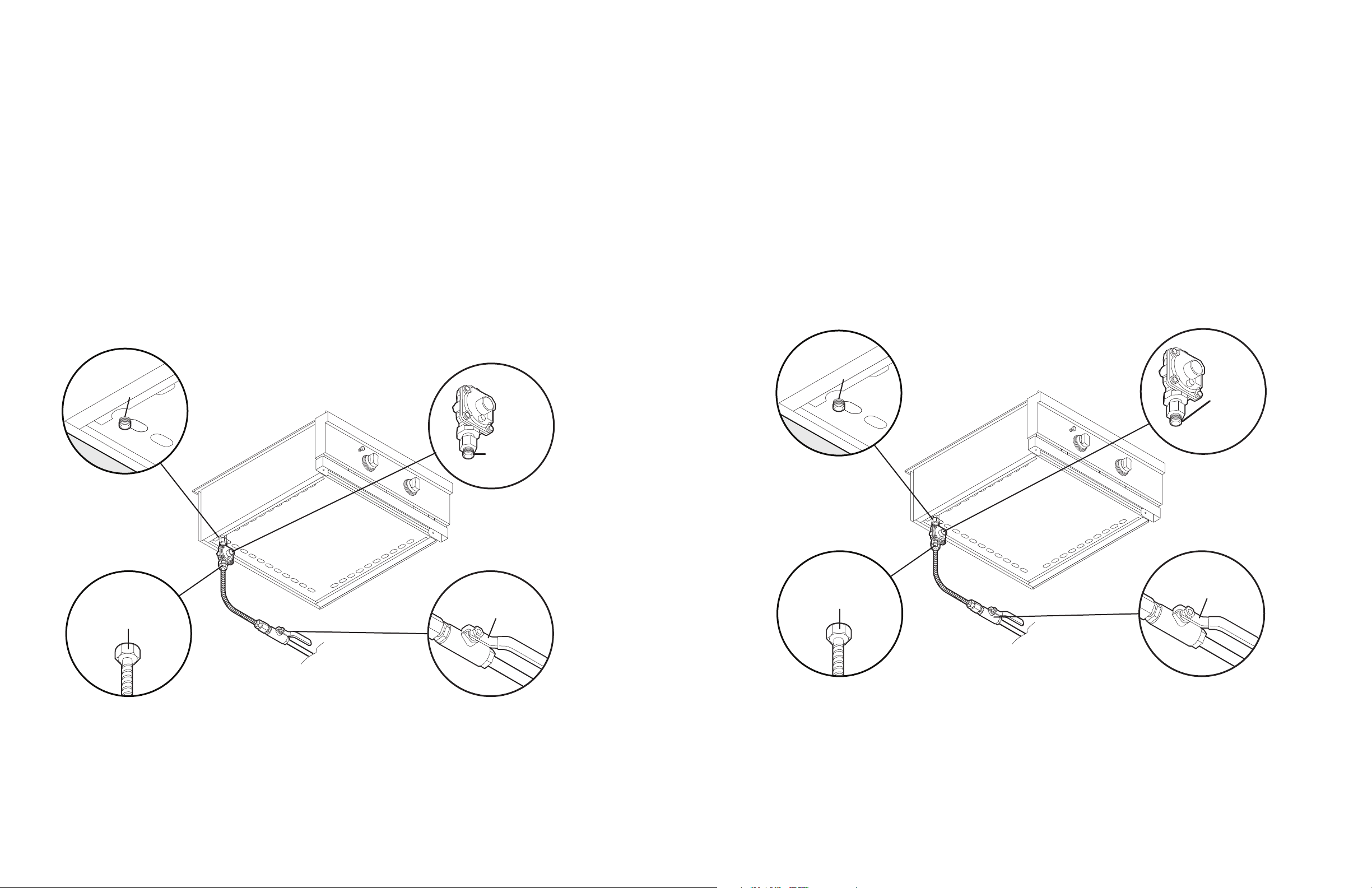
Natural Fixed Piping Connection
LP/PROPANE Fixed Piping Connection
Connection: Standard Residential 1/2” ID gas service line - 1/2” NPT male.
Operating Pressure: 4.0” W.C.P. Nat.
Supply Pressure: 6” to 10” W.C.P. Nat. If in excess of 10” W.C.P., a step-down regulator is required.
heck with your local gas utility company or with local codes for instructions on installing gas supply lines. Be sure to check on
C
ype and size of run and how deep to bury the lines. If the gas line is too small, the unit will not function properly.
t
To connect the supplied regulator assembly to the incoming flexible gas line, attach with a 7/8” (2.2 cm) female flare adaptor
to the 7/8” (2.2 cm) male flare adaptor on the regulator assembly. Ensure that the regulator arrow points in the direction of the
gas flow towards the unit and away from the supply. Connect the regulator assembly to the grill unit. All connectors need to
comply with ANSI Z21.75/ CSA 6.27. When using semi-ridged tubing, aluminum or aluminum alloy tubing is not permitted.
DDOO NNOOTT ffoorrggeett ttoo ppllaaccee tthhee iinnssttaalllleerr ssuupppplliieedd ggaass vvaallvvee iinn aann aacccceessssiibbllee llooccaattiioonn..
NNOOTTEE:: IIff uussiinngg aa VViikkiinngg GGSSHH1122 fflleexxiibbllee hhoossee,, rreemmoovvee tthhee 11//22”” ffllaarree aaddaapptteerr aanndd aattttaacchh hhoossee ttoo tthhee tthhee 77//88”” ((22..22 ccmm)) mmaalle