

Page 1

Viking Range, LLC
111 Front Street
Greenwood, Mississippi 38930 USA
(662) 455-1200
Installation Guide
For product information,
call 1-888-(845-4641)
or visit the Viking Web site at vikingrange.com in the U.S. or brigade.ca in Canada.
F21389 EN (053014)
NKVGR Natural Conversion Kit
for 700 Series Ranges/Rangetops
Page 2
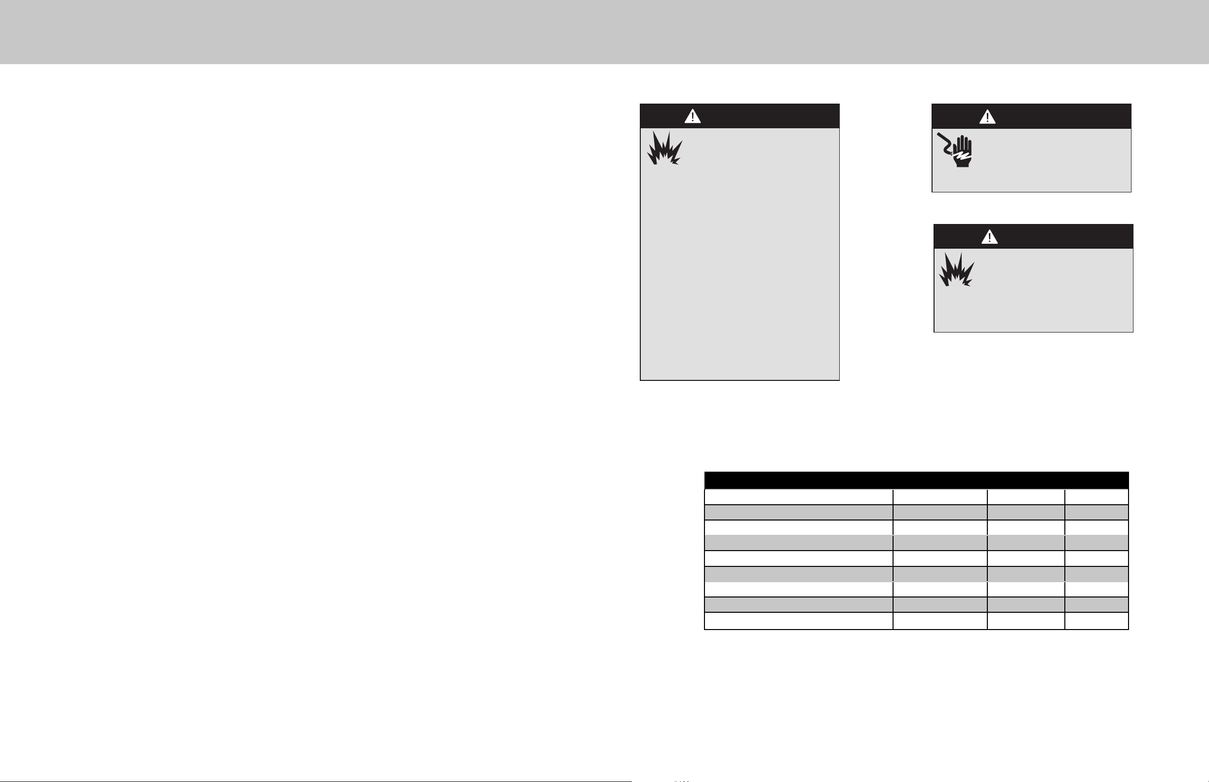
Table of Contents IMPORTANT - Please Read and Follow!
Warnings .......................................................................................................................... 3
Kit Contents ..................................................................................................................... 3
Regulator Conversion ...................................................................................................... 4
Infrared Broiler Conversion .............................................................................................. 5
Surface Burner Conversion .............................................................................................. 6
Griddle Conversion ......................................................................................................... 8
Oven Bake Burner Conversion ........................................................................................ 9
Rating Label locations ................................................................................................... 10
guide is not followed exactly, a fi re or
explosion may result causing property
damage, personal injury or death.
WHAT TO DO IF YOU SMELL GAS:
•DO NOT try to light any appliance.
•DO NOT touch any electrical switch.
•DO NOT use any phone in your building.
• Immediately call your gas supplier from
a neighbor's phone. Follow the gas
supplier's instructions.
• If you cannot reach your gas supplier, call
the fi re department.
Installation and service must be performed
by a qualifi ed installer, service agency, or
the gas supplier.
WARNING
FIRE/EXPLOSION
HAZARD
If the information in this
CAUTION
Be sure the electric power
is turned off at the breaker
box while the unit is being
converted.
CAUTION
Before placing the appliance
into operation, always check for
gas leaks with a soapy water
solution or other acceptable method.
DO NOT use an open fl ame to check for
leaks.
Natural Orifi ce Conversion Kit Contents
Description Part Number Size Quantity
Front Surface Burners In bag 050300-000 #44 (2.18 mm) 4
Rear Center/Right Rear Surface Burners In bag 050300-000 #51 (1.70 mm) 3
Left Rear Surface Burner In bag 050300-000 .048” (1.22mm) 1
Main Oven Burner 050279-000 #39 1
Left Oven (48” only) / Griddle Burner 050288-000 #50 2
Infrared Broiler Burner 050287-000 #48 1
Front Surface Burner Venturi 050576-000 4
Conversion label PF030377 1
NKVGR Conversion Instructions F21389 1
NOTE: Depending on the model being converted, some of the orifi ces may not be used.
2 3
Page 3
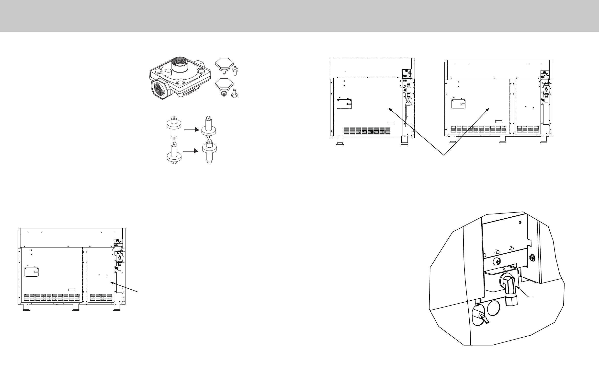
Regulator Conversion
•Remove hex nut from top of regulator.
•Unsnap plastic plunger from hex nut.
• Reverse plunger and reinstall onto hex nut by
pressing fi rmly.
Infrared Broiler Conversion
Natural
Orientation
NAT
NOTE: Plunger is marked “NAT” or “LP”.
Converted fuel type will be shown on the lower
portion of plunger.
• Reinstall hex nut onto regulator in confi guration
desired.
Apply sideways finger pressure
to remove pin from cap.
NAT
LP
NOTE: VGR748 models have two regulators. Make sure both regulators
are converted. To access second regulator, the island trim and small panel
on the back must be removed
LP
NAT
LP
LP
Orientation
conversion
conversion
Remove rear panel to access
infrared broiler orifi ce.
IMPORTANT: The infrared broiler orifi ce must
be changed from rear of range before unit is
installed. The island trim and rear panel must be
removed to access infrared broiler.
-Locate bag labeled 050287-000
- Remove nut securing 90 degree fi tting and
broiler tubing to rear of range.
- Remove orifi ce from 90º fi tting and replace with
orifi ce #48 from the bag labeled 050287-000.
Second regulator located behind small
panel on VGR748 Gas Ranges.
Reverse procedure to reassemble.
4 5
Broil Nut
Page 4
Surface Burner Conversion
Surface Burner Conversion
Preparing for Top Surface Conversion
Remove all grates, grate supports, surface burner caps, and griddle
NOTE: Some models may not be equipped with all parts mentioned above.
IMPORTANT: For models equipped with griddles, notice position of griddle temperature probe for proper reinstallation.
Failure to properly reinstall could result in damage to griddle temperature probe.
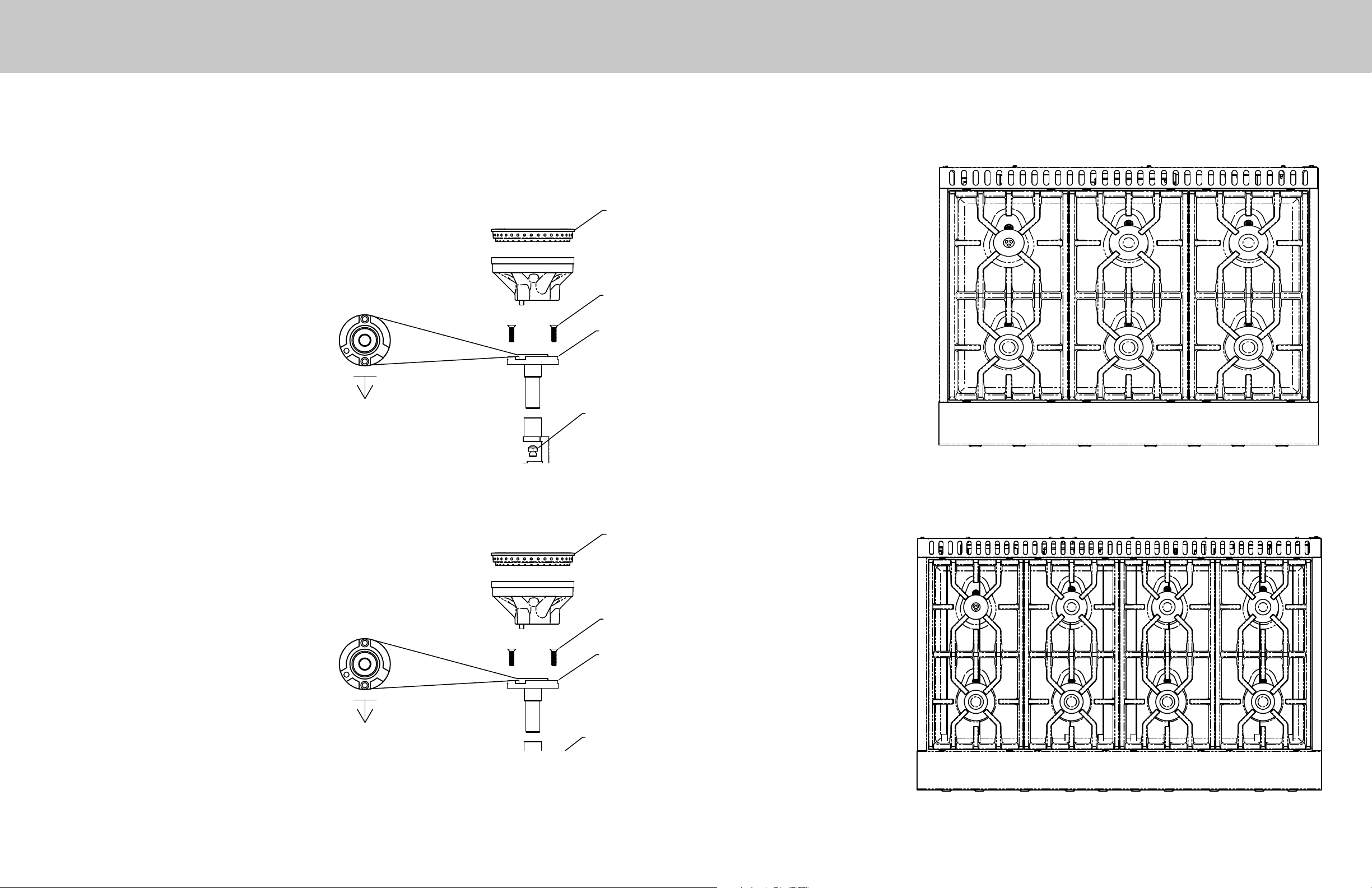
Front Surface Burner Conversion
-Locate bag labeled 050300-000
-Remove screws (Item #1) with a T-20 Torx bit.
-Remove venturi fl ange (Item #2).
-Use a metric 10mm nut driver to remove orifi ce (Item #3).
- Replace orifi ce with #44 from 050300-000 bag. The orifi ce
will have a violet color code ink and 086 stamped on the
orifi ce.
Tech tip: Tape can be applied to the inside of the socked
to assist in the removal of the surface burne
orifi ces. This can prevent the orifi ces from falling
into the range during removal.
- After replacing the orifi ce, replace Item#2 venturi fl ange
with Natural venturi fl ange labeled 050576-000. Note
orientation of venturi fl ange (refer to Top view of Venturi
fl ange).
-Reinstall screws and reverse procedure to reassemble.
Top View of
Venturi flange
Front of unit
Burner
Head
Item #1
Item #2
Item #3
Burner A #44 (2.18 mm)
Burner B #51 (1.70 mm)
Burner C .048” (1.22 mm)
36” Surface Burner Orifi ce Locations
C
(*Not applicable on
griddle models)
BB*
AA*A
(*Not applicable on
griddle models)
NOTE: For proper placement of the burner head, rotate until burner head seats into groove.
Rear Surface Burner Conversion
-Locate bag labeled 050300-000
-Remove screws (Item #1) with a T-20 Torx bit.
-Remove venturi fl ange (Item #2).
-Use a metric 10mm nut driver to remove orifi ce (Item #3).
- Replace left rear orifi ce with .048” from 050300-000 bag.
The orifi ce will have a dark green color code ink and 048
stamped on the orifi ce.
- Replace all other rear orifi ces with #51 from 050300-000
bag. The orifi ce will have a yellow color code ink and 067
stamped on the orifi ce.
Tech tip: Tape can be applied to the inside of the socked
to assist in the removal of the surface burner
orifi ces. This can prevent the orifi ces from falling
into the range during removal.
- After replacing the orifi ce, reinstall the current Item#2
venturi fl ange (it will not be replaced). Note orientation of
venturi fl ange (refer to Top view of Venturi fl ange).
-Reinstall screws and reverse procedure to reassemble.
NOTE: For proper placement of the burner head, rotate until burner head seats into groove.
Top View of
Venturi flange
Front of unit
Burner
Head
Item #1
Item #2
Item #3
Burner A #44 (2.18 mm)
Burner B #51 (1.70 mm)
Burner C .048 (.1.22 mm)
48” Surface Burner Orifi ce Locations
C
B
(*Not applicable on
griddle models)
AA
(*Not applicable on
griddle models)
B*
A*
B
A
6 7
Page 5
Screw (Front of Burner)
Oven Bake Burner ConversionGriddle Conversion (for models equipped with a griddle)
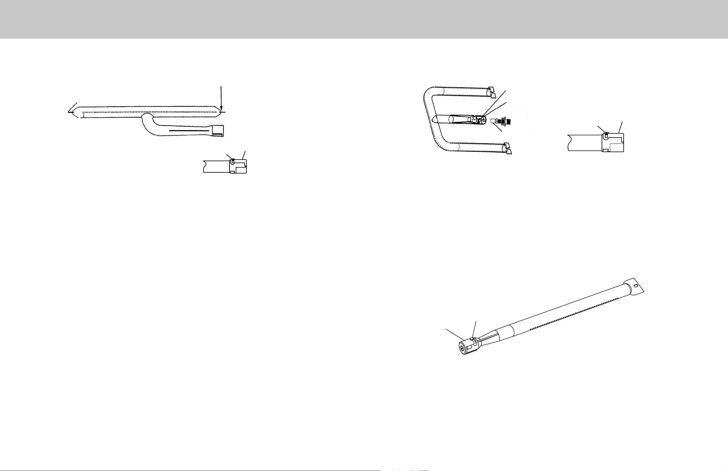
36” W. Oven and 48” W. Right Hand Oven Bake Burner
Air Shutter
Screw (Rear of Burner)
Adjustment
Screw
Air Shutter
-Locate bag labeled 050288-000.
-Remove griddle.
-Remove screws securing griddle burner to burner box.
-Loosen air shutter screw and adjust opening on burner to 7/16” and tighten air shutter screw.-
-Use a 1/2” deep socket wrench to remove orifi ce by turning counterclockwise.
-Install orifi ce (#50) from bag labeled 050288-000.
IMPORTANT: The orifi ce tip must be located 3/16” inside the burner for proper gas mixture
and combustion. The depth of the orifi ce can be adjusted by turning the orifi ce
counterclockwise (more depth) or clockwise (less depth).
Air Shutter
Set Screw
Adjustment
Screw
Orifice Hood
Air Shutter
-Remove oven racks.
-Remove oven bottom.
-Remove scews securing bake burner to oven burner box.
-Loosen air shutter screw and adjust opening on burner to 3/8” (.95 cm) and tighten air shutter screw.
-Remove orifi ce by turning counter-clockwise and replace with orifi ce (#39) from bag labeled 050279-000.
IMPORTANT: The orifi ce tip must be located 3/16” inside the burner for proper gas mixture and combustion. The
depth of the orifi ce can be adjusted by turning the orifi ce counterclockwise (more depth) or clockwise (less depth).
Reverse procedures as needed to reassemble.
48” W. Left Hand Oven Bake Burner
Reverse procedures as needed to reassemble.
Adjustment
Screw
Air Shutter
-Remove oven racks.
-Remove oven bottom.
-Remove screws securing bake burner to oven burner box.
-Loosen air shutter screw and adjust opening on burner to 3/8” (.95 cm) and tighten air shutter screw.
-Remove orifi ce by turning counter-clockwise and replace with orifi ce (#50) from bag labeled 050288-000.
IMPORTANT: The orifi ce tip must be located 3/16” inside the burner for proper gas mixture and combustion. The
depth of the orifi ce can be adjusted by turning the orifi ce counterclockwise (more depth) or clockwise (less depth).
Reverse procedures as needed to reassemble.
8 9
Page 6
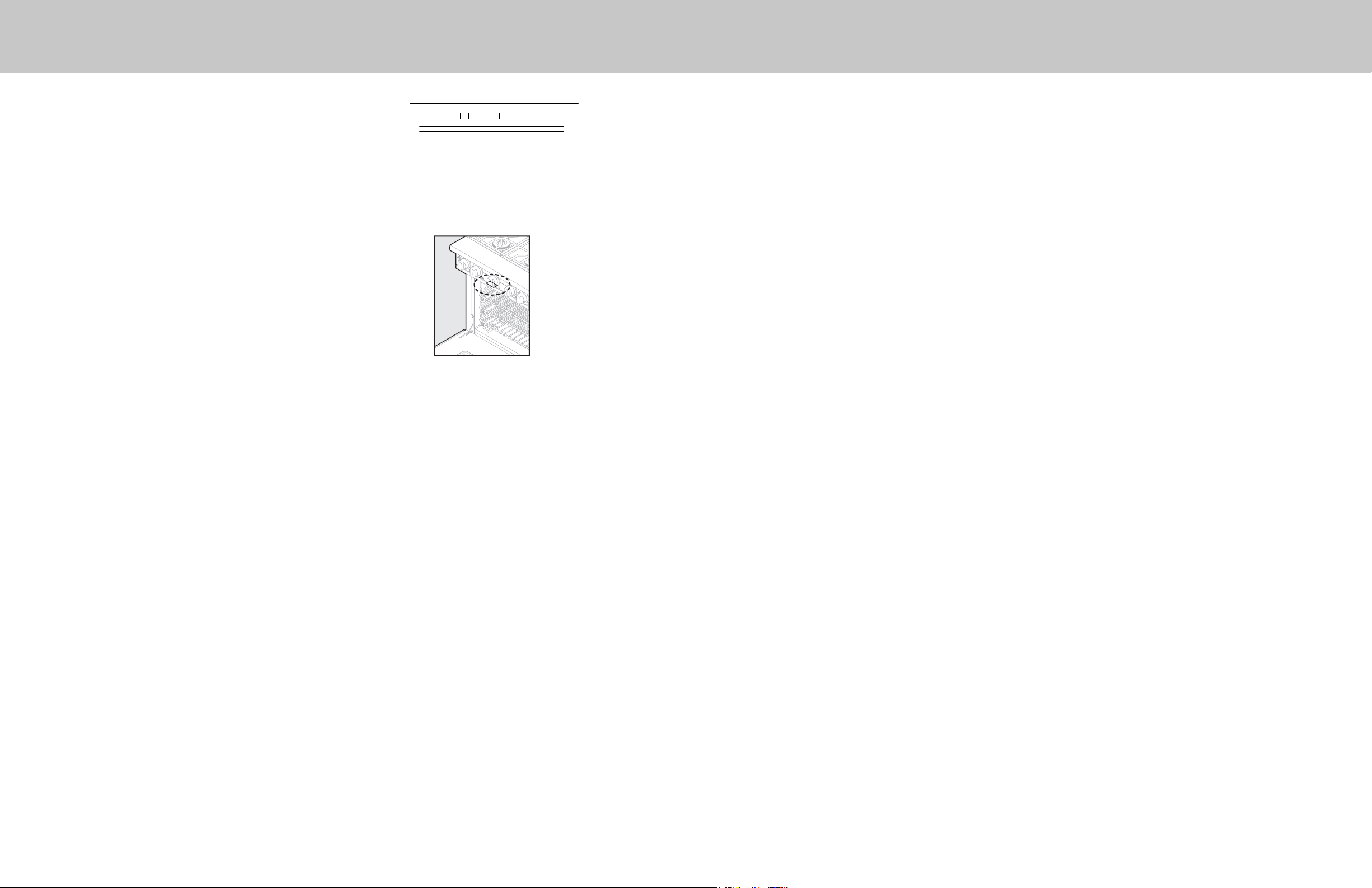
Rating Label Location
When the Natural conversion is complete, complete the enclosed
conversion label and place it next to the rating label.
The rating label is located under the control panel.
7KLVDSSOLDQFHZDVFRQYHUWHGRQ GD\PRQWK\HDUWR
E\
QDPHDQGDGGUHVVRIRUJDQL]DWLRQPDNLQJWKHFRQYHUVLRQZKLFK
DFFHSWVWKHUHVSRQVLELOLW\WKDWWKLVFRQYHVLRQKDVEHHQSURSHUO\
PDGH
1DWRU
/3JDV
3)
10 11
 Loading...