

Viking VGRT Installation Manual
Viking Range Corporation
111 Front Street
Greenwood, Mississippi 38930 USA
(662) 455-1200
For product information,
call 1-888-VIKING1 (845-4641)
or visit the Viking Web site at
vikingrange.com
F20056I EN
(033108J)
Viking Installation Guide
VGSB T-Series Outdoor 15” Wide Double Side
Burners & VGRT 24” Wide Outdoor Rangetop
GAS CONNECTION
Verify the type of gas supply to be used, either natural or LP, and make sure the marking on the rating plate agrees
with that of the supply. Never connect an unregulated gas line to the appliance. An installer supplied gas shut-off
valve must be installed in an easily accessible location. All installer supplied parts must conform to local codes, or in
the absence of local codes, with the National electrical Code, ANSI/NFPA 70 and the National Fuel Code, ANSI
Z223.1. In Canada: Installation must be in accordance with the current CAN/CGA-B149.1, Natural Gas Installation
Code or CAN/CGA-B149.2, Propane Installation Code and/or local codes. All pipe sealants must be an approved type
and resistant to the actions of LP gas. Never use pipe sealant on flare fittings. All gas connections should be made by
a competent technician and in accordance with local codes and or ordinances. In the absence of codes, the installation
must comply with the National Fuel Gas Code ANSI Z223.1.
The gas side burner and its individual shut-off valve must be disconnected from the gas supply piping system during
any pressure testing of that system at test pressures in excess of 1/2 PSIG (3.5 kPa). The unit must be isolated from the
gas supply piping system by closing its individual manual shut-off valve during any pressure testing of that sysptem at
test pressures equal to or les than 1/2 psi (3.5 kPa).
Built-in installations must be plumbed using a fixed/hard line if the unit is going to be operated at a
distance exceeding 3 feet (0.91 meters) from the fuel supply per ANSI Z21.24.
3
GENERAL INFORMATION
1. WARNING: This outdoor gas side burner is not intended to be installed in or on recreational vehicles
and/or boats.
2. WARNING: Keep electrical supply cord and the fuel supply hose away from heated surfaces.
3. Keep area clear and free from combustible materials, gasoline, and other flammable vapors.
4. When the outdoor gas side burner is not in use, the gas supply must be turned off at the LP gas supply cylinder.
5. The pressure regulator and hose assembly supplied with the unit must be used. Replacement pressure regulators
and hose assemblies must be those specified by the manufacturer.
6. Finding a leak is not a “do-it-yourself” procedure. Some leaks can only be found with the burner control in the on
position and this must be done by a qualified technician.
7. The LP supply cylinder to be used must be constructed and marked in accordance with the specifications for LP-gas
cylinders of the U.S. Department of Transportation (DOT) or the National Standard of Canada, CAN/CSA-B339,
Cylinders, Spheres, and Tubes for the Transportation of Dangerous Goods.
8. Gas Manifold Pressure - Natural gas - 4.0” W.C.P. LP/Propane - 10.0” W.C.P.
9. If the following instructions are not followed exactly, a fire causing death or serious injury may occur:
-Do not store a spare LP gas cylinder under or near this appliance.
-Never fill the cylinder beyond 80 percent full.
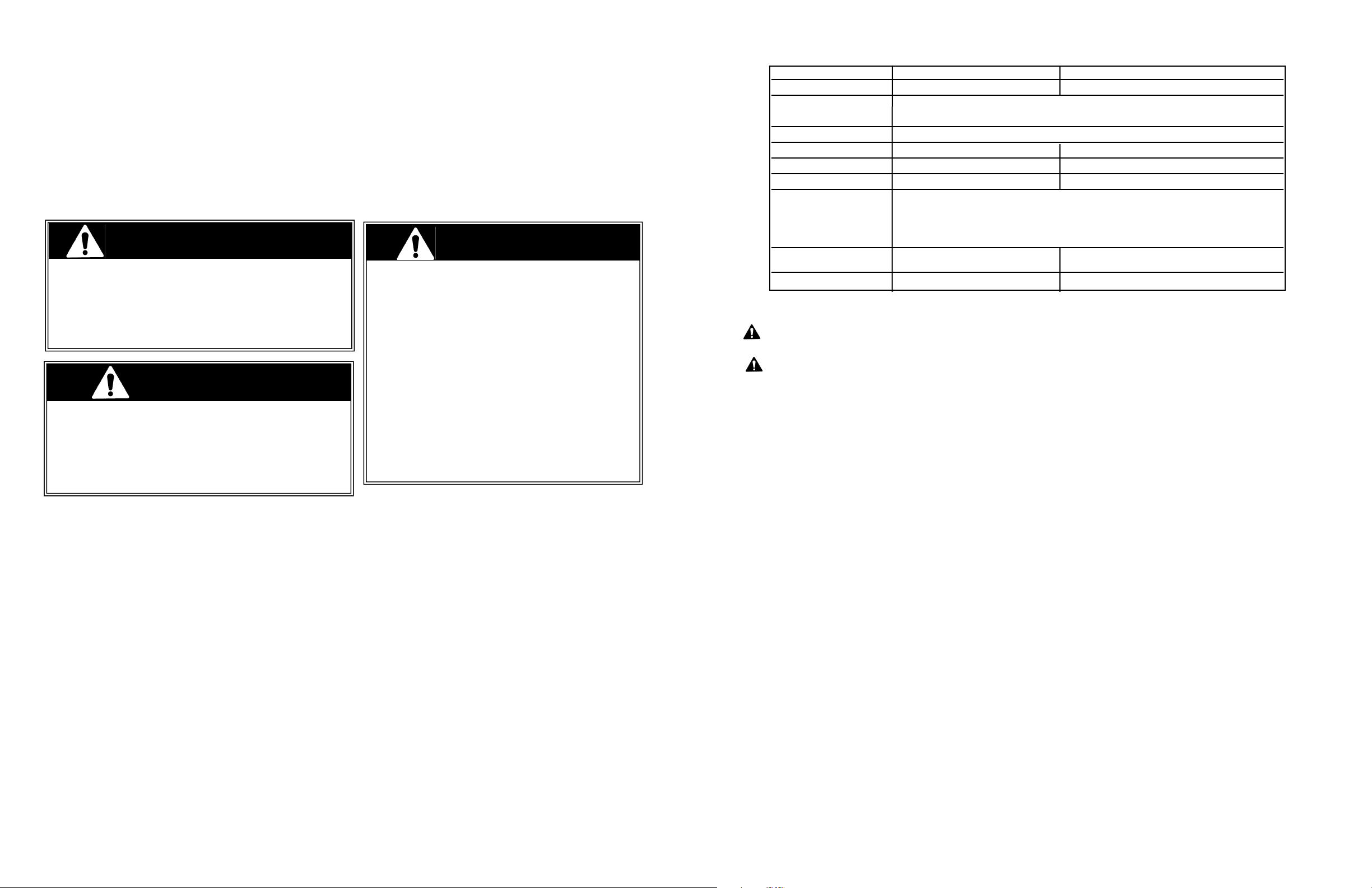
BASIC SPECIFICATIONS
Description VGSB152T VGRT244T
Overall Width 15-5/16” (38.9 cm) 26 1/4” (66.7 cm)
Overall Depth To end of landing ledge 31-9/16” (80.2 cm)
To end of knobs 32-5/8” (82.9 cm)
Overall Height To cooking surface 10 1/2” (26.3 cm)
Cutout Width 14 ” (35.6 cm) 24 3/4” (62.9 cm)
Cutout Depth 27-1/2” (69.9 cm) 27-1/2” (69.9 cm)
Cutout Height 10-1/4” (26.0 cm) 10-1/4” (26.0 cm)
Gas Natural: standard residential 1/2” (1.3 cm) ID gas service line.
Requirements LP/Propane: equipped with high capacity hose/regulator assembly for connection
to standard 5gal, 20 lb. LP/Propane gas cylinder with Type 1, QCC-1
connection or standard residential 1/2” (1.3 cm) ID gas service line.
Side Burner (2) - 15,000 BTU Nat./13,500 BTU LP (4) - 15,000 BTU Nat./13,500 BTU LP
Rating (4.4 kW Nat./4.0 kW LP) (4.4 kW Nat./4.0 kW LP)
Approximate Shipping Wt. 80 lbs. (36.3 kg) 160 lbs (72.0 kg)
IMPORTANT: PLEASE READ AND FOLLOW
1. Before beginning, please read these instructions completely and carefully.
2. Do not remove permanently affixed labels, warnings, or plates from product. This may void the warranty
3. Please observe all local and national codes and ordinances.
4. The installer should leave these instructions with the consumer who should retain for local inspector’s use and for
future reference
Installation must conform with local codes or in the absence of codes, the National Fuel Gas Code, ANSI Z223.1.
In Canada: Installation must be in accordance with the current CAN/CGA-B149.1, Natural Gas Installation Code or
CAN/CGA-B149.2, Propane Installation Code and/or local codes.
If you smell gas:
1. Shut off gas to the appliance.
2. Extinguish any open flame.
3. Open lid.
4. If odor continues, immediately call your gas supplier or your
fire department.
1. Do not store or use gasoline or other flammable vapors
and liquids in the vicinity of this or any other appliance.
2. Any LP cylinder not connected for use shall not be stored
in the vicinity of this or any other appliance.
If not installed, operated and maintained in
accordance with the manufacturer’s instructions, this
product could expose you to substances in fuel or
fuel combustion which can cause death or serious
illness and which are known to cause cancer, birth
defects or other reproductive harm.
For example, benzene is a chemical which is
part of the gas supplied to the cooking
product. It is consumed in the flame during
combustion. However, exposure to a small
amount of benzene is possible if a gas leak
occurs. Formaldehyde and soot are byproducts of incomplete combustion. Properly
adjusted burners with a bluish rather than
yellow flame minimize incomplete combustion.
2
FOR YOUR SAFETY
WARNING
FOR YOUR SAFETY
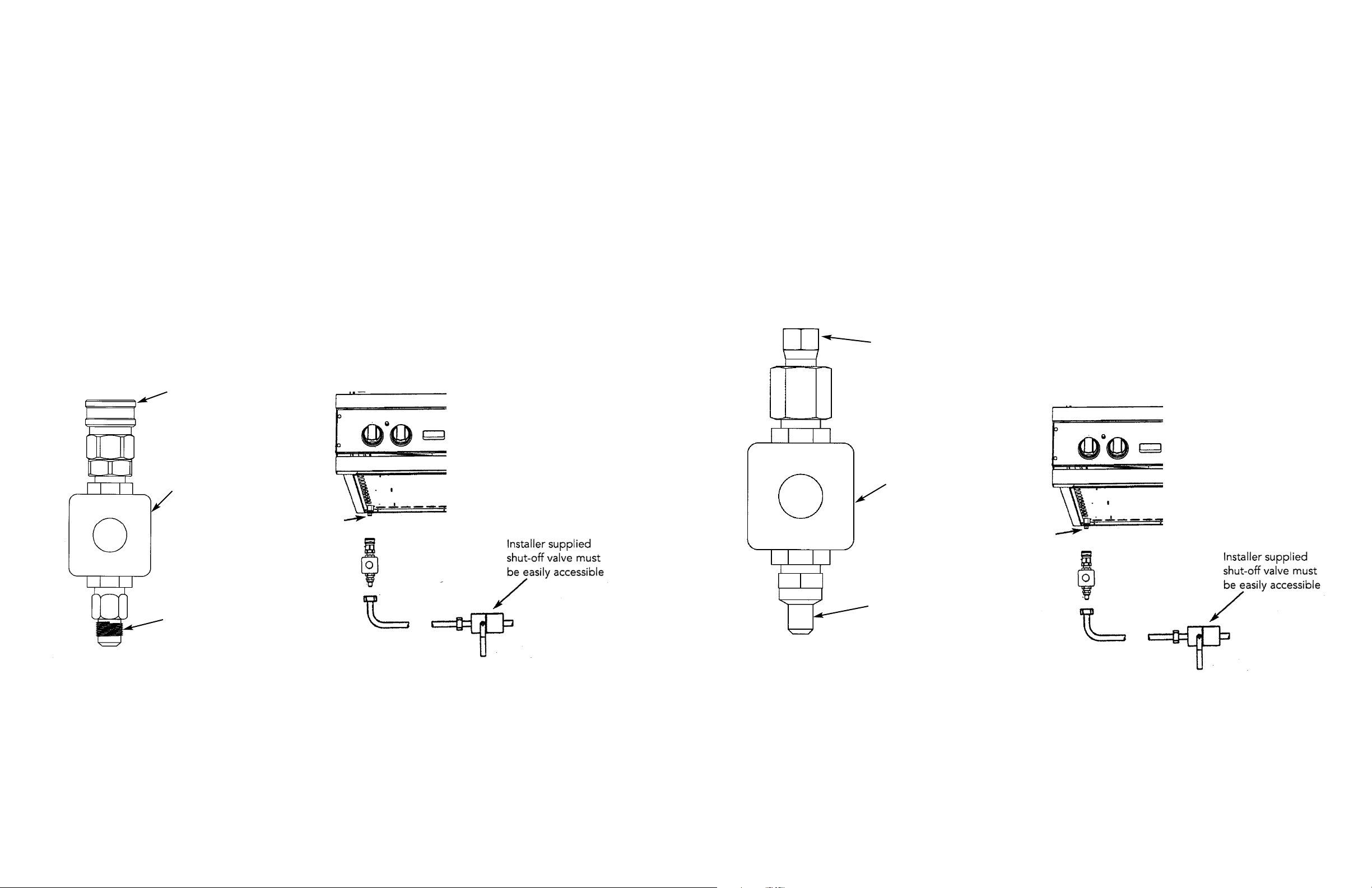
LP/PROPANE FIXED PIPING CONNECTION
Connection: Standard Residential 1/2” ID gas service line - 1/2” NPT male with 3/8” flare adapter.
Operating Pressure: 10.0” W.C.P. Nat.
Supply Pressure: 11” to 14” W.C.P. Nat. If in excess of 14” W.C.P., a step-down regulator is required.
Check with your local gas utility company or with local codes for instructions on installing gas supply lines. Be sure to check on
type and size of run and how deep to bury the lines. If the gas line is too small, the grill will not function properly.
To connect the supplied regulator assembly to the incoming flexible gas line, attach with a 3/8” female flare adaptor to the
3/8” male flare adaptor to the regulator assembly. Ensure that the regulator arrow points in the direction of the gas flow
towards the unit and away from the supply. Attach the regulator assembly to the grill unit with the 3/8” flemale flare adapter
on the regulator assembly to the 3/8” male flare adaptor on the grill.
DO NOT forget to place the installer supplied gas valve in an accessible location.
3/8” female
flare adaptor
Regulator
3/8” male
flare adaptor
Regulator Assembly
3/8” Male
flare
adaptor
Installer supplied flexible
gas line with 3/8”
female flare adaptor or
Viking GHS12
Regulator Assembly
Female
coupler sleeve
Regulator
1/2” male
flare adaptor
Male
coupler
fitting
Installer supplied flexible
gas line with 1/2”
female flare adaptor or
Viking GHS12
NATURAL FIXED PIPING CONNECTION
Connection: Standard Residential 1/2” ID gas service line - 1/2” NPT male with 1/2” flare adapter.
Operating Pressure: 4.0” W.C.P. Nat.
Supply Pressure: 6” to 14” W.C.P. Nat. If in excess of 14” W.C.P., a step-down regulator is required.
Check with your local gas utility company or with local codes for instructions on installing gas supply lines. Be sure to check on
type and size of run and how deep to bury the lines. If the gas line is too small, the grill will not function properly.
To connect the supplied regulator assembly to the incoming flexible gas line, attach with a 1/2” (1.3 cm) female flare adaptor
to the 1/2” (1.3 cm) male flare adaptor on the regulator assembly. Ensure that the regulator arrow points in the direction of the
gas flow towards the unit and away from the supply. Attach the regulator assembly to the grill unit by pulling back the female
coupler sleeve towards the regulator. Insert the coupler into themale coupler fitting on the grill until the sleeve snaps forward
securing the connection. DO NOT forget to place the installer supplied gas valve in an accessible location.
NOTE: If using a Viking GSH12 flexible hose, remove the 3/8” flare adapter and attach hose to the the 1/2” (1.3 cm) male
flare on the regulator assembly.
5
4
 Loading...