

Viking VGR73624GBF, VGR73624GBORGLP, VGR73626BCY, VGR74826GCY, VGR74828BCY Installation Manual
...
Installation
Professional Freestanding Ranges /
Built-in Rangetops
VGR7362, VGR7482,
VDR7362, CVDR7362, VDR7482, CVDR7482
VRT736, VRT748,

2
Warnings & Important Safety Instructions _________________________________________________3
Dimensions / Specifications - Rangetops __________________________________________________6
Dimensions - Ranges __________________________________________________________________7
Specifications - Ranges ________________________________________________________________8
Clearance Dimensions (Proximity to Cabinets)_____________________________________________10
Clearance Dimensions (Wood/Composite Overlay) _________________________________________11
Electrical & Gas Requirements _________________________________________________________12
Installation - Rangetops _______________________________________________________________14
Installation - Ranges__________________________________________________________________15
Door Removal ___________________________________________________________________15
Leg Installation __________________________________________________________________16
Electrical Connection (3-wire) ______________________________________________________17
Electrical Connectin (4-wire)________________________________________________________19
Leveling/Adjustments/Alignment ___________________________________________________20
Anti-tip Device Installation _________________________________________________________22
Standoff Spacer Removal __________________________________________________________24
Final Installation _________________________________________________________________24
Door Replacement _______________________________________________________________25
Final Preparation ____________________________________________________________________25
Performance Checklist ________________________________________________________________26
Service & Registration ________________________________________________________________27
Table of Contents
3
• Before beginning, please read these instructions
completely and carefully.
• DO NOT remove permanently affixed labels,
warnings, or plates from product. This may void the
warranty.
• All local and national codes and ordinances must
be observed. Installation must conform with local
codes or in the absence of codes, the National Fuel
Gas Code ANSI Z223.1 INFPA54.
• The installer must leave these instructions with the
consumer who should retain for local inspector’s
use and for future reference.
In Canada: Installation must be in accordance with
the current CAN/CGA B149.1 & 2 Gas Installation
codes and/or local codes. Electrical installation must
be in accordance with the current CSA C22.1 Canadian
Electrical Codes
Part 1 and/or local codes.
In Massachusetts: All gas products must be installed
by a “Massachusetts” licensed plumber or gasfitter. A
“T” type handle manual valve must be installed in the
gas supply line to the appliance.
An air curtain or other overhead range hood which
operates by blowing a downward airflow onto the
range, shall not be used with a gas range
Your safety and the safety of others is very
important.
We have provided many important safety
messages in this manual and on your
appliance. ALWAYS read and obey all
safety messages.
This is the safety alert symbol. This
symbol alerts you to hazards that
can kill or hurt you and others.
All safety messages will be preceded by the
safety alert symbol and the word “DANGER,”
“WARNING” or “CAUTION.” These words mean:
Hazards or unsafe practices
which WILL result in severe personal
injury or death.
DANGER
Hazards or unsafe practices
which COULD result in severe personal injury
or death.
Hazards or unsafe practices which COULD
result in minor personal injury or property
damage.
All safety messages will identify the
hazard, tell you how to reduce the chance
of injury, and tell you what can happen if
the instructions are not followed.
WARNING
CAUTION
IMPORTANT– Read and Follow!
4
DANGER
FIRE/EXPLOSION HAZARD
IF THE INFORMATION IN THIS
MANUAL IS NOT FOLLOWED
EXACTLY, A FIRE OR EXPLOSION
MAY RESULT CAUSING PROPERTY
DAMAGE, PERSONAL INJURY, OR DEATH.
• DO NOT store or use gasoline or other
flammable vapors and liquids in the vicinity
of this or any other appliance.
• WHAT TO DO IF YOU SMELL GAS:
–DO NOT try to light any appliance.
–DO NOT touch any electrical switch;
DO NOT use any phone in your building.
–Immediately call your gas supplier from a
neighbor’s phone.
–Follow the gas supplier’s instructions.
–If you cannot reach your gas supplier, call
the fire department.
• Installation and service must be performed
by a qualified installer, service agency, or the
gas supplier.
A GFI shall be used if required by NFPA-70 (National Electric Code), federal/state/local laws, or local
ordinances.
• The required use of a GFI is normally related to the location of a receptacle with respect to any
significant sources of water or moisture.
• Viking Range, LLC will NOT warranty any problems resulting from GFI outlets which are not installed
properly or do not meet the requirements below.
If the use of a GFI is required
, it should be:
• Of the receptacle type (breaker type or portable type NOT recommended)
• Used with permanent wiring only (temporary or portable wiring NOT recommended)
• On a dedicated circuit (no other receptacles, switches or loads in the circuit)
• Connected to a standard breaker of appropriate size (GFI breaker of the same size NOT
recommended)
• Rated for Class A (5 mA +/- 1 mA trip current) as per UL 943 standard
• In good condition and free from any loose-fitting gaskets (if applicable in outdoor situations)
• Protected from moisture (water, steam, high humidity) as much as reasonably possible
WARNING
To prevent possible damage to cabinets and
cabinet finishes, use only materials and
finishes that will not discolor or delaminate
and will withstand temperatures up to 194°F
(90°C). Heat resistant adhesive must be used if
the product is to be installed in laminated
cabinetry. Check with your builder or cabinet
supplier to make sure that the materials meet
these requirements.
IMPORTANT– Read and Follow!
5
DANGER
GAS LEAK HAZARD
To avoid risk of personal injury or
death; leak testing of the
appliance must be conducted
according to the manufacturer’s
instructions. Before placing appliance in
operation, always check for gas leaks with
soapy water solution.
• DO NOT USE AN OPEN FLAME TO CHECK
FOR GAS LEAKS.
DANGER
ELECTRICAL SHOCK
HAZARD
To avoid risk of electrical shock,
personal injury or death; verify
your appliance has been properly grounded
in accordance with local codes or in absence
of codes, with the National Electrical Code
(NEC) ANSI/NFPA-70 – latest edition.
WARNING
MOVING HAZARD
To avoid risk of severe personal
injury; this appliance requires
two or more personnel while
handling and moving. Possible
use of appliance moving devices is
recommended.
DANGER
CHEMICAL HAZARD
To avoid risk of property
damage and/or personal injury
or death; this appliance is not
too be used as a heating source.
• Benzene is a chemical which is part of the
gas supply to this cooking product, which
is consumed in the flames during
combustion. Exposure to a small amount of
benzene is possible if a gas leak occurs.
Formaldehyde and soot are by-products of
incomplete combustion.
• This appliance contains or produces
chemicals which can cause serious injury or
death and which are known to the state of
California to cause cancer, birth defects or
other reproductive harm. To reduce the risk
from substances in the fuel or from fuel
combustion make sure this appliance is
installed, operated, and maintained in
accordance to the instructions in this
document.
WARNING
TIPPING HAZARD
To reduce the risk of property
damage or personal injury;
install anti-tipping device
provided in accordance with the
installation instructions in this
document. Device must be
engaged properly to prevent
product from tipping over.
• THIS RANGE CAN TIP
• INJURIES TO PERSONS CAN
RESULT
• INSTALL ANTI-TIP DEVICE PACKED
WITH RANGE
• SEE INSTALLATION INSTRUCTIONS
IMPORTANT– Read and Follow!
6
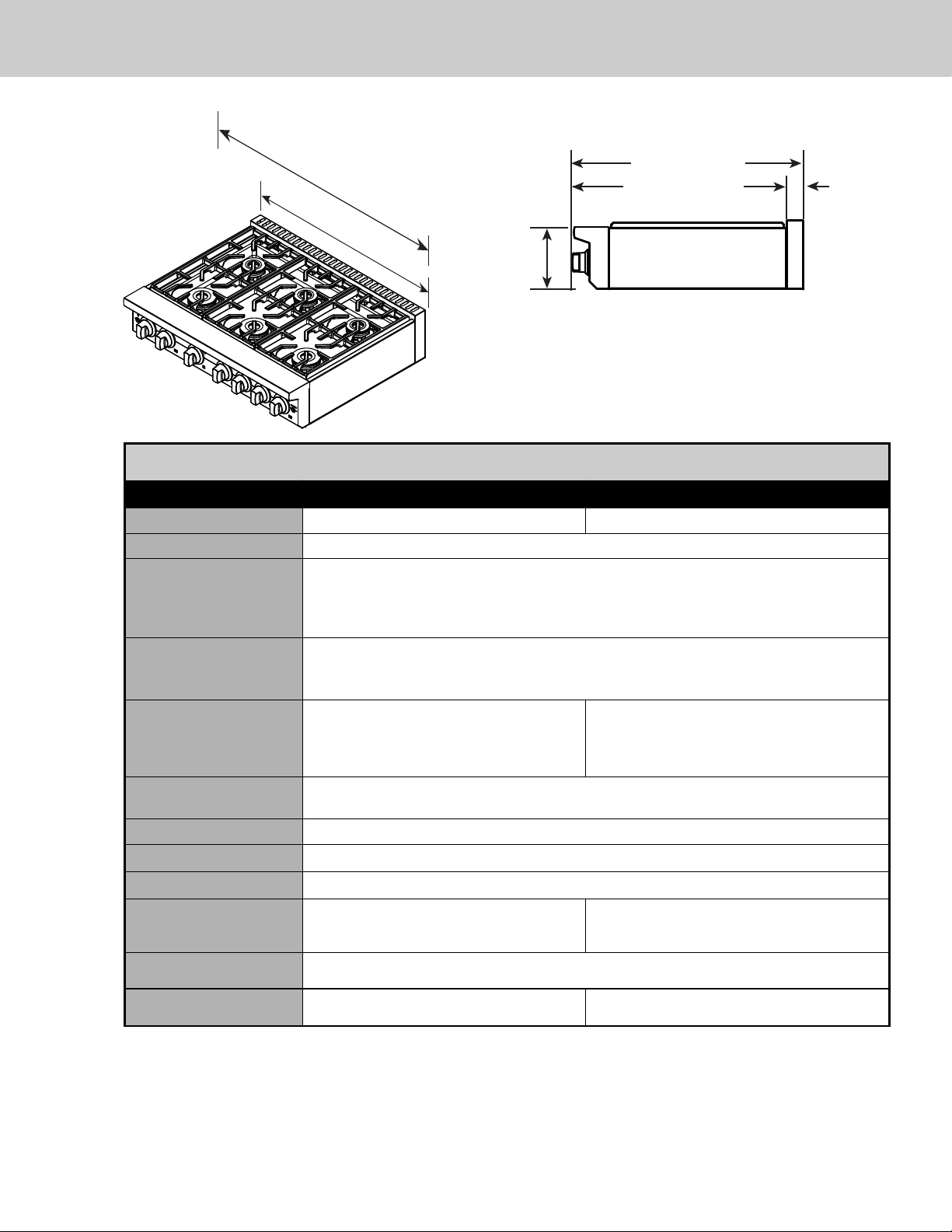
Dimensions / Specifications - 36”/48” Rangetop
Note:
Unit shown with standard island trim.
Minimum clearances from adjacent combustible construction
• Cooking surface and below, i.e., 36” (91.4 cm) and below -Sides—0”
• Above cooking surface, i.e. above 36" (91.4 cm) Sides—12” (30.5 cm)
o Within 12” (30.5 cm) side clearance, wall cabinets no deeper than 13” (33.0 cm) must be minimum 18” (45.7 cm) above cooking surface.
o Wall cabinets directly above product must be minimum 58” (147.3 cm) for open top burners above cooking surface.
o Rear—with island trim - 6” (15.2 cm) to ombustible rear wall; 0” to non-comabustible rear wall.
o Rear—with backguaard or high shelf - 3” (7.6 cm) to ombustible rear wall; 0” to non-comabustible rear wall.
7 Series Gas Rangetops
Description
36” W. Models 48” W. Models
Overall width 35-7/8” (91.1 cm) 47-7/8” (121.6 cm)
Overall height (from bottom) To top of side panel - 8” (20.3 cm)
Additions to overall
height
To top of grate— add 3/4” (1.9 cm)
To top of island trim— add 1” (2.5 cm)
To top of backguard—add 10” (25.4 cm)
To top of high shelf—add 24-1/8” (61.3 cm)
Overall depth
(from rear)
To end of side panel—25-1/4” (64.1 cm)
To end of landing edge—29-3/4” (75.6 cm)
To end of knobs—30” (76.2 cm)
Cutout dimensions
Cutout width—36” (91.4 cm)
Cutout height—7-5/8” (19.4 cm)
Cutout depth—min. 24” (61.0 cm),
max. 25-1/4” (64.1 cm)
Cutout width—48” (121.9 cm)
Cutout height—7-5/8” (19.4 cm)
Cutout depth—min. 24” (61.0 cm),
max. 25-1/4” (64.1 cm)
Gas requirements Shipped natural or LP/Propane gas; field convertible with conversion kit
(purchased separately); minimum required service line 1/2” (1.3 cm) ID.
Gas manifold pressure Natural 5.0” W.C.P. / Liquid propane L/P 10.0” W.C.P.
Electrical requirements
120 VAC/60 Hz 4ft. (121.9 cm), 3-wire cord with grounded 3-prong plug
Max. amp usage 0.5 amps
Surface burner rating
Natural/LP
(3) Front 23,000 BTU (6.7 kW)/20,000 BTU (5.8kW)
(2) Rear 15,000 BTU (4.4 kW)/13,500 BTU (4.0 kW)
(1) Rear 8,000 BTU (2.3 kW)/8,000 BTU (2.3 kW)
(4) Front 23,000 BTU (6.7 kW)/20,000 BTU (5.8kW)
(3) Rear 15,000 BTU (4.4 kW)/13,500 BTU (4.0 kW)
(1) Rear 8,000 BTU (2.3 kW)/8,000 BTU (2.3 kW)
Griddle burner rating
Natural/LP(If applicable)
15,000 BTU (4.4 kW)/13,500 BTU (4.0 kW)
Approximate
shipping weight
203 lbs. (92.1 kg) 257 lbs. (116.6 kg)
47-7/8”
(121.6 cm)
30” (76.2 cm)
27-3/4” (70.5 cm)
35-7/8”
(91.1 cm)
8”
(20.3 cm)
2-1/4”
(5.7 cm)
7
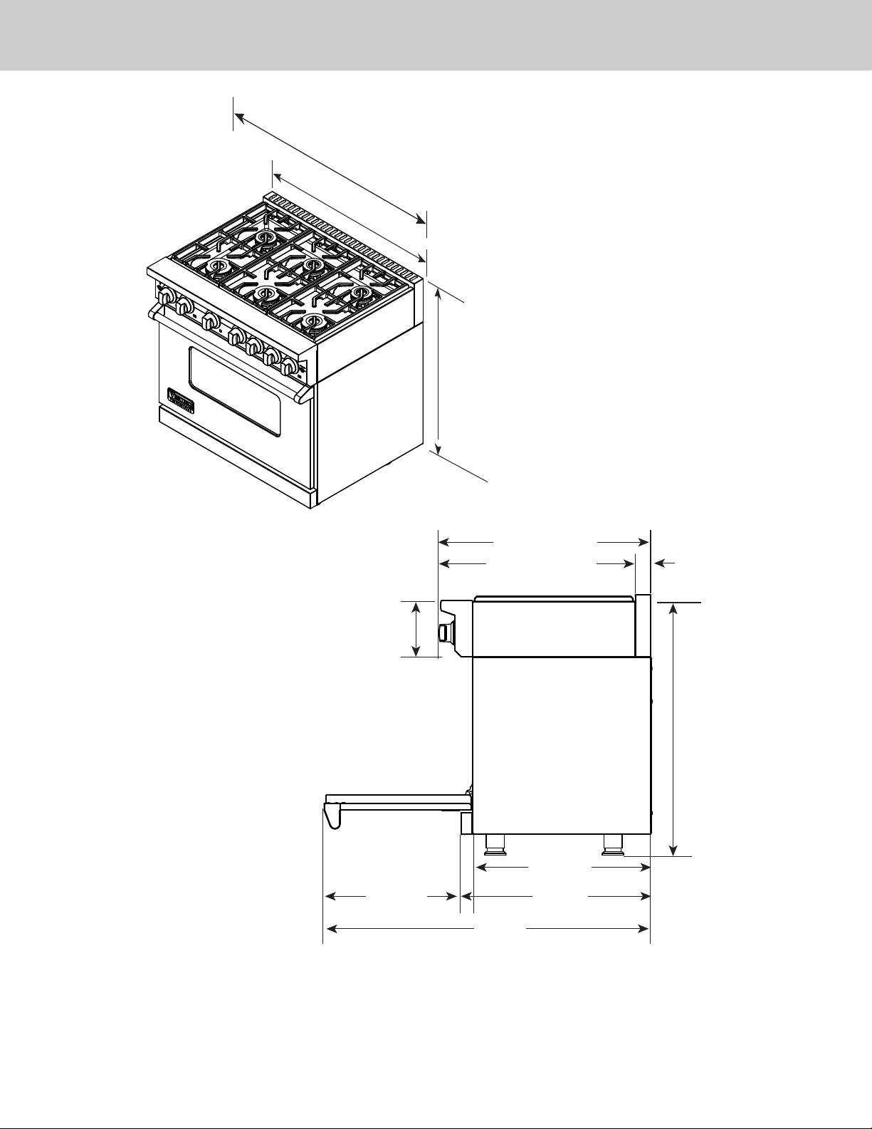
Note: Unit shown with standard island trim.
Note: All ranges installed with a backguard against a combustible wall require a standoff with the
backguard which will add 3/4” (1.9 cm) to the overall range depth.
Dimensions - 36”/48” Ranges
47-7/8”
(121.6 cm)
35-7/8”
(91.1 cm)
35-15/16”
(91.3 cm) min.
to
37-9/16”
(95.4 cm) max.
8”
(20.3 cm)
19-3/8”
(49.2 cm)
30” (76.2 cm)
27-3/4 (70.5 cm)
26-15/16”
46-5/16”
(117.6 cm)
2-1/4”
(5.7 cm)
35-15/16”
(91.3 cm) min.
to
37-9/16”
(95.4 cm) max.
25-1/4”
(64.1 cm)
(68.4 cm)
8
Minimum clearances from adjacent combustible construction:
Below cooking surface (36” [91.4 cm] and below)
• Sides - 0”
• Top grate support - 36” (91.4 cm)
Above cooking surface (above 36” [91.4 cm])
• Sides - 12” (30.5 cm)
• Within 12” (30.5 cm) side clearance, wall cabinets no deeper than 13” (33.0 cm) must be minimum 18” (45.7 cm) above cooking
surface
• Wall cabinets directly above product must be a minimum of 58” (147.3 cm) above cooking surface, unless a range hood is installed
above the cooking surface.
• Rear - 3/4” (1.9 cm) with 10” backguard or high shelf; 0” with island trim and non-combustible rear wall;
• 6” (15.2 cm) with island trim and combustible rear wall
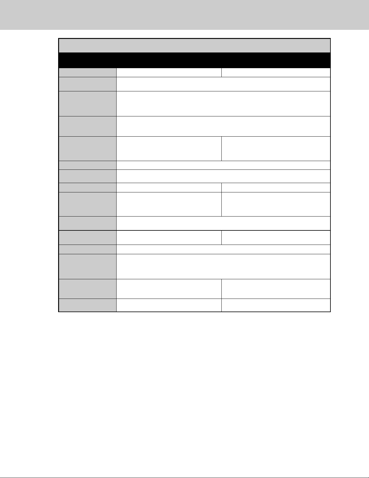
Gas 36” and 48” W. Ranges
Description
36” W. Models 48” W. Models
Overall width 35-7/8” (91.1 cm) 47-7/8” (121.6 cm)
Overall height To top of side trim – 35-15/16” (91.3 cm) min. 37-9/16” (95.4 cm) max.
Legs adjust – 1-5/8” (4.1 cm)
Overall depth from
rear*
To end of side panel – 25-1/4” (64.1 cm)
To front of door – 26-15/16” (68.4 cm)
To end of door handle – 30” (76.2 cm)
*Add 3/4” (1.9 cm) to overall depth for models installed against a combustible wall.
Additions to Base
Height
To top of island trim – add 1” (.5 cm)
To top of backguard – add 10” (25.4 cm)
To top of high shelf – add 24-1/8” (61.3 cm)
Gas requirements Shipped Natural or LP/Propane, accepts
standard residential 1/2” (1.3 cm) ID gas
service line. Unit is field convertible with
proper conversion kit
Shipped Natural or LP/Propane, accepts
standard residential 3/4” (1.9 cm) ID gas service
line. Unit is field convertible with proper
conversion kit
Gas manifold pressure Natural 5.0” W.C.P./ Liquid Propane L/P 10.0” W.C.P.
Electrical
requirements
120VAC/60 Hz; 4 ft. (121.9 cm), 3-wire cord with grounded
3-prong plug attached to unit
Maximum amp usage 1.5 amps 2.0 amps
Surface burner rating
Natural gas/LP
Front: (3) 23,000 BTU (6.7 kW) / 20,000 BTU (5.8 kW)
Rear: (2) 15,000 BTU (4.4 kW) / 13,500 BTU (4.0 kW)
(1) 8,000 BTU (2.3 kW) / 8,000 BTU (2.3 kW)
Front: (4) 23,000 BTU (6.7 kW) / 20,000 BTU (5.8 kW)
Rear: (3) 15,000 BTU (4.4 kW) / 13,500 BTU (4.0 kW)
(1) 8,000 BTU (2.3 kW) / 8,000 BTU (2.3 kW)
Griddle burner rating
15,000 BTU (4.4 kW) / 13,500 BTU (4.0 kW)
Oven interior width 29” (73.7 cm) Right oven - 23” (58.4 cm)
Left oven - 12-1/2” (31.8 cm)
Oven interior height
16-1/8” (40.9 cm)
Oven interior depth
Overall
AHAM
18-3/4 (47.6 cm)
17” (43.2 cm)
Oven volume
Overall
AHAM
5.1 cu. ft.
5.1 cu. ft.
Right - 4.0 cu. ft. / Left - 2.2 cu. ft.
Right - 3.8 cu. ft. / Left - 2.2 cu. ft.
Approximate
shipping weight
525 lbs. (236.6 kg) 641 lbs. (288.5 kg)
Specifications
Note: Clearances from non-combustible materials are not part of the ANSI Z21.1 scope and not certified by CSA. Clearances
to non-combustible materials must be approved by the authority having jurisdiction.
9
Minimum clearances from adjacent combustible construction:
Below cooking surface (36” [91.4 cm] and below)
• Sides - 0”
• Top grate support - 36” (91.4 cm)
Above cooking surface (above 36” [91.4 cm])
• Sides - 12” (30.5 cm)
• Within 12” (30.5 cm) side clearance, wall cabinets no deeper than 13” (33.0 cm) must be minimum 18” (45.7 cm) above
cooking surface
• Wall cabinets directly above product must be a minimum of 58” (147.3 cm) above cooking surface, unless a range hood is
installed above the cooking surface.
• Rear - 3/8” (0.9 cm) with 10” backguard or high shelf; 0” with island trim and non-combustible rear wall;
• 6” (15.2 cm) with island trim and combustible rear wall
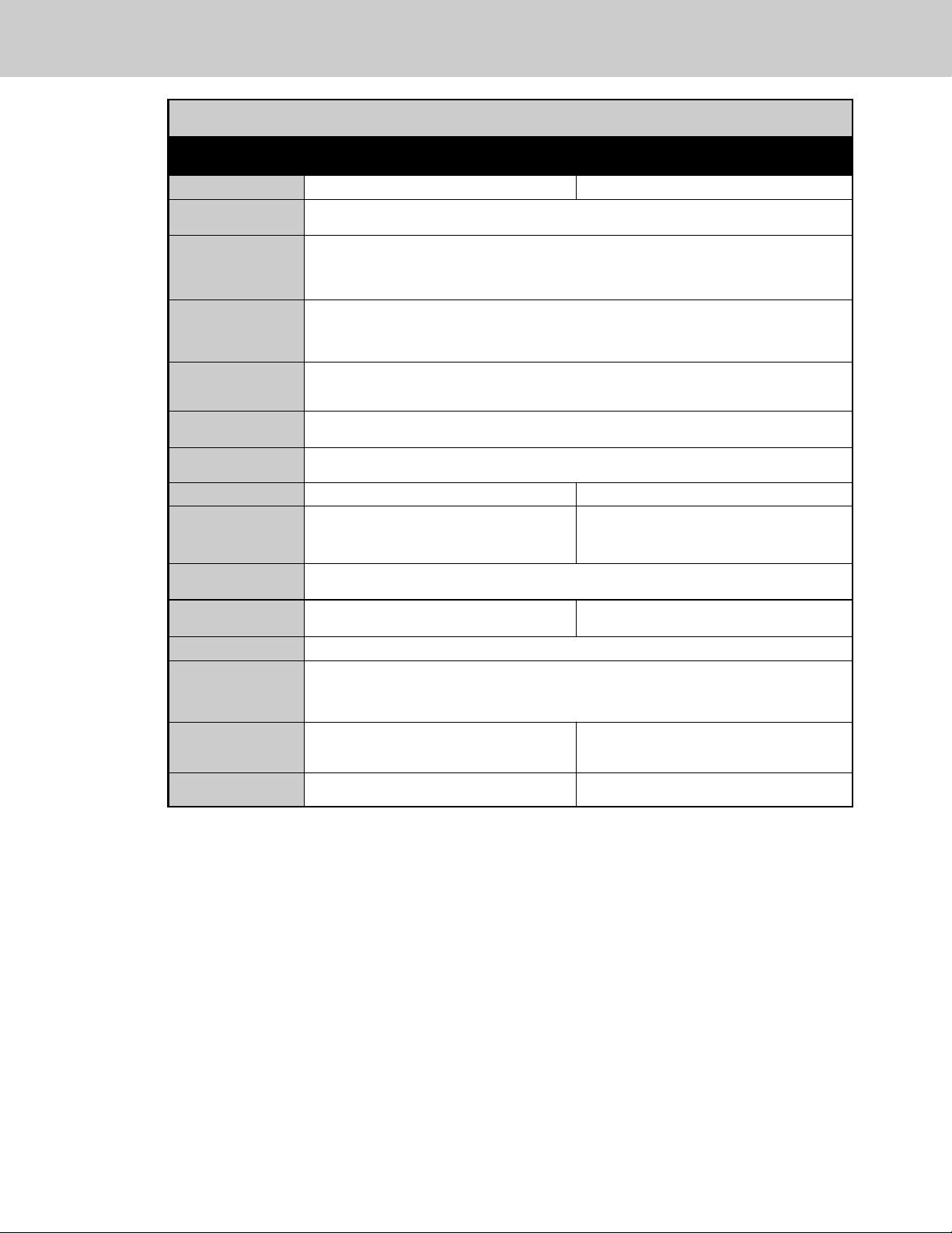
Dual Fuel 36” and 48” W. Ranges
Description
36” W. Models 48” W. Models
Overall width 35-7/8” (91.1 cm) 47-7/8” (121.6 cm)
Overall height To top of side trim – 35-15/16” (91.3 cm) min. 37-9/16” (95.4 cm) max.
Legs adjust – 1-5/8” (4.1 cm)
Overall depth from
rear*
To end of side panel – 25-1/4” (64.1 cm)
To front of door – 26-15/16” (68.4 cm)
To end of door handle – 30” (76.2 cm)
*Add 3/8” (1 cm) to overall depth for models installed against a combustible wall.
Additions to Base
Height
To top of island trim – add 1” (2.5 cm)
To top of backguard – add 10” (25.4 cm)
To top of high shelf – add 24-1/8” (6.3 cm)
Gas requirements Shipped Natural or LP/Propane, accepts standard residential 1/2” (1.3 cm) ID gas service line.
Unit is field convertible with proper conversion kit.
Gas manifold
pressure
Natural 5.0” W.C.P./ Liquid Propane L/P 10.0” W.C.P.
Electrical
requirements
See Electrical Requirements information
Maximum amp usage 240V - 28.5 amps / 208V - 24.7 amps 240V - 43.0 amps / 208V - 37.3 amps
Surface burner rating
Natural gas/LP
Front: (3) 23,000 BTU (6.7 kW) / 21,500 BTU (6.3 kW)
Rear: (2) 15,000 BTU (4.4 kW) / 13,500 BTU (4.0 kW)
(1) 8,000 BTU (2.3 kW) / 8,000 BTU (2.3 kW)
Front: (4) 23,000 BTU (6.7 kW) / 21,500 BTU (6.3 kW)
Rear: (3) 15,000 BTU (4.4 kW) / 13,500 BTU (4.0 kW)
(1) 8,000 BTU (2.3 kW) / 8,000 BTU (2.3 kW)
Griddle burner rating
15,000 BTU (4.4 kW) / 13,500 BTU (4.0 kW)
Oven interior width 30-5/16” (77.0 cm) Right oven - 25-5/6” (65.6 cm)
Left oven - 13-3/4” (34.9 cm)
Oven interior height
16-1/2” (41.9 cm)
Oven interior depth
Overall
AHAM
19-1/2” (49.5 cm)
16-13/16” (42.7 cm)
Oven volume
Overall
AHAM
5.6 cu. ft.
4.9 cu. ft.
Right - 4.7 cu. ft. / Left - 2.6 cu. ft.
Right - 4.1 cu. ft. / Left - 2.2 cu. ft.
Approximate
shipping weight
525 lbs. (236.6 kg) 692 lbs. (288.5 kg)
Note: Clearances from non-combustible materials are not part of the ANSI Z21.1 scope and not certified by CSA. Clearances
to non-combustible materials must be approved by the authority having jurisdiction.
Specifications
 Loading...