

Viking VGR30, VGR36-6B, VGR36-4G, VGR48-4Gl, VGR48-6G Service Manual
...
SERVICE MANUAL
FREE STANDING GAS RANGE

TABLE OF CONTENTS
Viking Model Numbers................................... 2
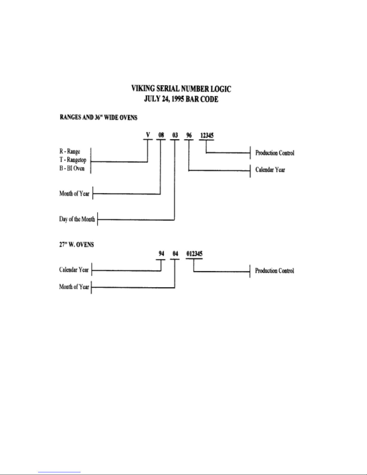
Viking Serial Number logic............................. 3
Viking Product Warrenty................................. 4
Proximity to Side Cabinets Installation........... 6
Gas Connections............................................ 7
Rangetop Cutout and Specifications............... 8
Range Leveling............................................... 9
Combustion of Gas........................................ 10
BTU Requirements......................................... 12
Gas Conversion............................................... 13
I / R Broiler Spud (Orifice) Change.............. 14
Surface Burner Adjustments............................ 15
Oven Burner Adjustments............................... 16
Grill / Griddle Burner Adjustment................... 17
Oven Temperature Calibration Chart................ 18
Oven Thermostat / Calibration.......................... 19
Silicon Carbide (Glow-Coil) Ignition............... 20
Door Removal.................................................. 21
Oven Door Assembly....................................... 22
Hinge and Logo Removal................................ 22
Door Hinge Removal...........................................22
Oven Door Parts..................................................22
Control Panel Removal..................................... 23
Landing Ledge Removal................................... 23
Component Location...........................................24
Top Burner Removal........................................ 25
Top Burner Ignitor Removal........................... 25
Spark Module Removal................................... 25
Indicator Light Removal.................................. 26
Bake / Broil Thermostat Removal.................... 26
Oven Ignitor Removal..................................... 26
Broil Gas Valve Removal................................. 26
Oven Gas Valve Removal................................. 26
Top Burner Valve Replacement........................ 27
Pressure Regulator Removal............................ 27
Convection Fan Removal................................. 27
Oven Burner Removal..................................... 27
Broil Burner Removal...................................... 28
Broil Ignitor Removal....................................... 28
Indicator Light.................................................. 28
Oven Light Switch........................................... 28
Oven Light Switch Removal............................ 28
Oven Gasket Removal..................................... 28
Convection Fan Removal................................. 28
Oven Light Removal........................................ 29
Grill Burner Removal....................................... 29
Grill Ignitor Removal....................................... 29
Griddle Thermostat Removal........................... 29
Trouble Shooting Guide.................................... 30
Griddle Repaie Kit.(12") griddle...................... 34
Griddle Repair Kit (24")................................... 35
Wiring Diagram (Rangetops)............................ 36
Wiring Diagram (convection Ranges)............... 37
2
NEW VIKING MODEL NUMBERS
RANGES AND RANGETOPS
V G R C 4 8 5 4 G Q D S S
V-Viking Color
AL-Almond
G-Gas Bk-Black
BU-Burgundy
SS-24" D EW-Euro White
Standard Range (30"W) FG-Forest Green
SC-27" D PL-Plum
Convection Range (30"W) SS-Stainless Steel
VB-Viking Blue
RC-27" D WH-White
Convection Range (36"/48"W) GG-Graphite Gray
RT-24" D LN-Linen
Rangetop
Width
30"
36"
48" D-Oven Door Window
60"
Q-12" Wide Grill
0-Standard Oven
5-Convection Oven G-Griddle
12" Wide
24" Wide
Number of Surface Burners
3
4

VIKING RANGE CORPORATION
PRODUCT WARRANTY
COOKING PRODUCTS
FREE STANDING GAS RANGES
90 DAYS-GLASS, PAINTED, PORCELAIN AND
*
DECORATIVE ITEMS
* 1 YEAR FULL WARRANTY-COMPONENTS AND
ACCESSORIES
* 5 YEAR LIMITED WARRANTY-SURFACE BURNER,
GRIDDLE TUBULAR BURNER, GRILL TUBULAR
BURNER (PART ONLY)
* 10 YEAR LIMITED WARRANTY-ANY PORCELAIN
OVEN OR PORCELAIN INNER DOOR WHICH RUSTS
THROUGH
DUAL FUEL RANGES
* 90 DAYS-GLASS, PAINTED, PORCELAIN AND
DECORATIVE ITEMS
* 1 YEAR FULL WARRANTY-COMPONENTS AND
ACCESSORIES
* 5 YEAR LIMITED WARRANTY-SURFACE BURNER,
GRIDDLE TUBULAR BURNER, GRILL TUBULAR
BURNER, BAKE ELEMENT, BROIL ELEMENT, OR
CONVECTION COOK ELEMENT (PART ONLY)
* 10 YEAR LIMITED WARRANTY-ANY PORCELAIN
OVEN OR PORCELAIN INNER DOOR PANEL WHICH
RUSTS THROUGH
ELECTRIC RANGES
* 90 DAYS-GLASS, PAINTED, PORCELAIN AND
DECORATIVE ITEMS
* 1 YEAR FULL WARRANTY-COMPONENTS AND
ACCESSORIES
* 5 YEAR-ANY HALOGEN ELEMENT, BAKE
ELEMENT, BROIL ELEMENT, OR CONVECTION
COOK ELEMENT (PART ONLY)
* 10 YEAR LIMITED WARRANTY-ANY PORCEOAIN
OVEN OR PORCELAIN INNER DOOR PANEL WHICH
RUSTS THROUGH
GAS RANGETOPS
* 90 DAYS -GLASS, PAINTED, PORCELAIN AND
DECORATIVE ITEMS
* 1 YEAR FULL WARRANTY-COMPONENTS AND
ACCESSORIES
* 5 YEAR LIMITED WARRANTY-SURFACE BURNERS,
GRIDDLE TUBULAR BURNER, GRILL TUBULAR
BURNER (PART ONLY)
ELECTRIC RANGETOP
* 90 DAYS-GLASS, PAINTED, PORCELAIN AND
DECORATIVE ITEMS
* 1 YEAR FULL WARRANTY-COMPONENTS AND
ACCESSORIES
* 5 YEAR-ANY HALOGEN ELEMENT, BAKE
ELEMENT, BROIL ELEMENT, OR CONVECTION
COOK ELEMENT (PART ONLY)
GAS WALL OVENS
* 90 DAYS-GLASS, PAINTED, PORCELAIN AND
DECORATIVE ITEMS
* 1 YEAR FULL WARRANTY-COMPONENTS AND
ACCESSORIES
* 5 YEARS-OVEN TUBULAR BURNER (PART ONLY)
* 10 YEAR LIMITED WARRANTY-ANY PORCELAIN
OVEN OR PORCELAIN INNER DOOR PANEL WHICH
RUSTS THROUGH
ELECTRIC WALL OVENS
* 90 DAYS-GLASS, POINTED, PORCELAIN AND
DECORATIVE ITEMS
* 1 YEAR FULL WARRANTY-COMPONENTS AND
ACCESSORIES
* 5 YEARS LIMITED WARRANTY-OVEN BAKE,
BROIL,OR CONVECTION HEATING ELEMENTS
* 10 YEAR LIMITED WARRANTY-ANY PORCELAIN OR
PORCELAIN INNER DOOR PANEL WHICH RUSTS
THROUGH
WARMING DRAWERS
* 90 DAYS-PAINTED AND DECORATIVE ITEMS
* 1 YEAR FULL WARRANTY-COMPONENTS AND
ACCESSORIES
* 5 YEAR LIMITED WARRANTY-HEATING ELEMENT
VENTILATION PRODUCTS
* 90 DAYS-PAINTED AND DECORATIVE ITEMS
* 1 YEAR FULL WARRANTY-COMPONENTS AND
ACCESSORIES
* 2 YEAR LIMITED WARRANTY-BLOWER MOTOR
OR EXTERIOR VENTILATOR MOTOR
KITCHEN CLEAN-UP
DISHWASHER
* 90 DAYS-PAINTED OR DECORATIVE ITEMS
* 1 YEAR FULL WARRANTY-COMPONENTS AND
ACCESSORIES
* 5 YEAR LIMITED WARRANTY-MOTOR/PUMP AND
WATER DISTRIBUTION SYSTEM COMPONENTS
* CIRCULATION PUMP
* DRAIN MOTOR/PUMP
* FILL V ALVE
* LOWER WASH ARM
* TUBE TO UPPER WASH ARM
* UPPER WASH ARM
* 25 YEAR LIMITED WARRANTY-STAINLESS STEEL
TANK OR INNER DOOR LINER WHICH DEVELOPS A
WATER LEAK
TRASH COMPACTORS
* 90 DAYS-PAINTED OR DECORATIVE ITEMS
* 1 YEAR FULL WARRANTY-COMPONENTS AND
ACCESSORIES
* 5 YEAR LIMITED WARRANTY-DRIVE SYSTEM
MOTOR
DISPOSERS
* VCFW 1020 AND VBFW
* 7 YEAR FULL WARRANTY
* VCHW 1000 AND VBHW 1030
* 5 YEAR FULL WARRANTY
5

PRODUCT WARRANTY (CONTINUED)
REFRIGERATION PRODUCTS
REFRIGERATION
* 90 DAYS-PAINTED OR DECORATIVE ITEMS
* 2 YEARS FULL WARRANTY
* 6 YEARS FULL WARRANTY ON SEALED SYSTEM
COMPONENTS
* COMPRESSOR
* CONDENSER
* DRYER/STRAINER
* EVAPORATOR
* CONNECTING TUBING
* 12 YEAR LIMITED WARRANTY-SEALED SYSTEM
COMPONENT (PARTS ONLY)
* COMPRESSOR
* CONDENSER
* DRYER/STRAINER
* EVAPORATOR
* CONNECTING TUBING
ICE MAKER
* 90 DAYS-PAINTED OF DECORATIVE ITEMS\
* 2 YEAR FULL WARRANTY
* 6 YEAR FULL WARRANTY ON SEALED SYSTEM
COMPONENT
* COMPRESSOR
* CONDENSER
* DRYER/STRAINER
* EVAPORATOR
* CONNECTING TUBING
* 12 YEAR LIMITED WARRANTY-SEALED SYSTEM
COMPONENT (PART ONLY)
* COMPRESSOR
* CONDENSER
* DRYER/STRAINER
* EVAPORATOR
* CONNECTING TUBING
WINE COOLER
* 90 DAYS-PAINTED OR DECORATIVE ITEMS
* 2 YEAR FULL WARRANTY
* 6 YEAR FULL WARRANTYON SEALED SYSTEM
COMPONENT
* COMPRESSOR
* CONDENSER
* DRYER/STRAINER
* EVAPORATOR
* CONNECTING TUBING
* 12 YEAR LIMITED WARRANTY-SEALED SYSTEM
COMPONENT (PART ONLY)
* COMPRESSOR
* CONDENSER
* DRYER/STRAINER
* EVAPORATOR
* CONNECTING TUBING
OUTDOOR PRODUCTS
GAS GRILLS
ITEMS
* 90 DAY-PAINTED, PORCELAIN, AND DECORATIVE
* 1 YEAR FULL WARRANTY
* 5 YEAR LIMITED WARRANTY-CAST IRON BURNER
ASSEMBLIES, INFRARED ROTISSERIE BURNERS,
AND PORCE LAIN GRILL GRATES
* LIFETIME WARRANTY-STAINLESS STEEL PART
WHICH RUST THROUGH
6
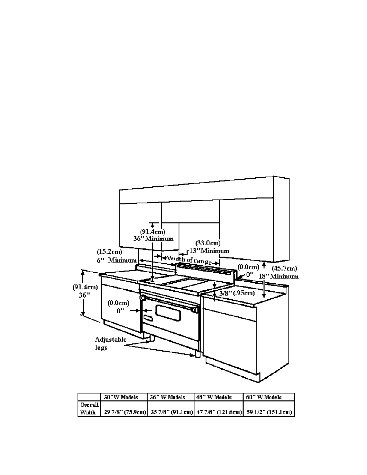
PROXIMITY TO SIDE CABINET INSTALLATION
1. This range may be installed directly adjacent to existing 36" high base cabinets.
IMPORTANT- the top grate support MUST BE 3/8" above the adjacent base cabinet coun tertop. This m ay
be accomplished by raising the unit using the adjustment spindles on the legs. (The countertops CANNOT
be higher than 37 1/2" due to the high BTU burners.)
2. The range CANNOT be installed directly adjacent to sidewalls, tall cabinets, tall appliances, or other side
vertical surfaces above 36" high. There must be a minimum of 6" side clearance from the range to such
combustible surfaced above the counter height.
3. Within the 6" side clearance to com bustible vertical surf aces above 36", the maxim um w all cabinet depth must
be 13" and wall cabinets within 6" side clearance must be 18" above the 36" high countertop.
4. Wall cabinets above the range must be a m inimum of 36" above the range cook ing surface f or the full width of
the range.
7
GAS CONNECTIONS
The gas supply (service) line must be the same size or greater than the inlet line of the appliance. This range
uses a ½" I.D. NPT (Sch40) inlet. Sealant on all pipe joints must be resistive to Lp gas.
1. Manual Shut-off Valve:
This installer supplied valve must be installed
in the gas service line ahead of the appliance
and regulator in
reached quickly in the event of an emergency.
2. Pressure Regulator:
a) All heavy-duty, commercial-type cooking
equipment must have a pressure regulator on
the incoming service line for safe and efficient
operation, since service pressure may fluctuate
with local demand. External regulators are not
required on this range, because a regulator is
built into each unit at the factory. UNDER NO
CONDITION BYPASS THIS BUILT-IN
REGULATOR.
b) Any conversion required must be performe d
by your dealer or a qualified licensed plumber
or gas service company. Please provide the
service person with this manual before work is
started on the range.
( GAS CONVERSIONS ARE THE
RESPONSIBILITY OF THE DEALER OR
END USER.)
c) This range can be used with Natural gas or
LP/Propane. It is shipped from the factory
adjusted for use with natural gas. The orifice
hoods must be screwed snug when
LP/Propane is used. (See LP/Propane
conversion).
d) Manifold pressure should be checked w ith a
manometer, natural gas requires 5.0"WC and LP
gas requires 10.0"WC. Incoming line pressure
upstream from the regulator must be 1.0"WC
higher than the manifold pressure in order to
check the regulator. The regulator used on this
range can withstand a maximum
a position where it can be
input pressure
e) The appliance, its individual shut-off valve,
and pressure regulator must be disconnected
from the gas supply piping system during any
pressure testing of that system at pressures in
excess of 1/2psig (3.45kPa).
f) The appliance must be isolated from the gas
supply piping system by closing its individual
manual shut-off valve during any pressure testing
of the gas piping system at test pressures equal to
or less than ½ psig (3.45kPa).
3. Flexible Connections:
a) If the unit is to be installed with flexible
couplings and/or quick-disconnect fittings, the
installer must use a heavy duty, A.G.A. design
certified commercial flexible connector of at lea st
½" ID NPT ( with suitable strain reliefs) in
compliance with ANSI Z21.69.
b) In Canada: CAN 1-6. 10-88 metal
connectors for gas appliance and CAN 1-6.9
M79 quick disconnect devices for use with gas
fuel.
of ½ PSI (14.0" WC). If the line pressure is
in excess of that amount, a step-down
regulator will be required.
8
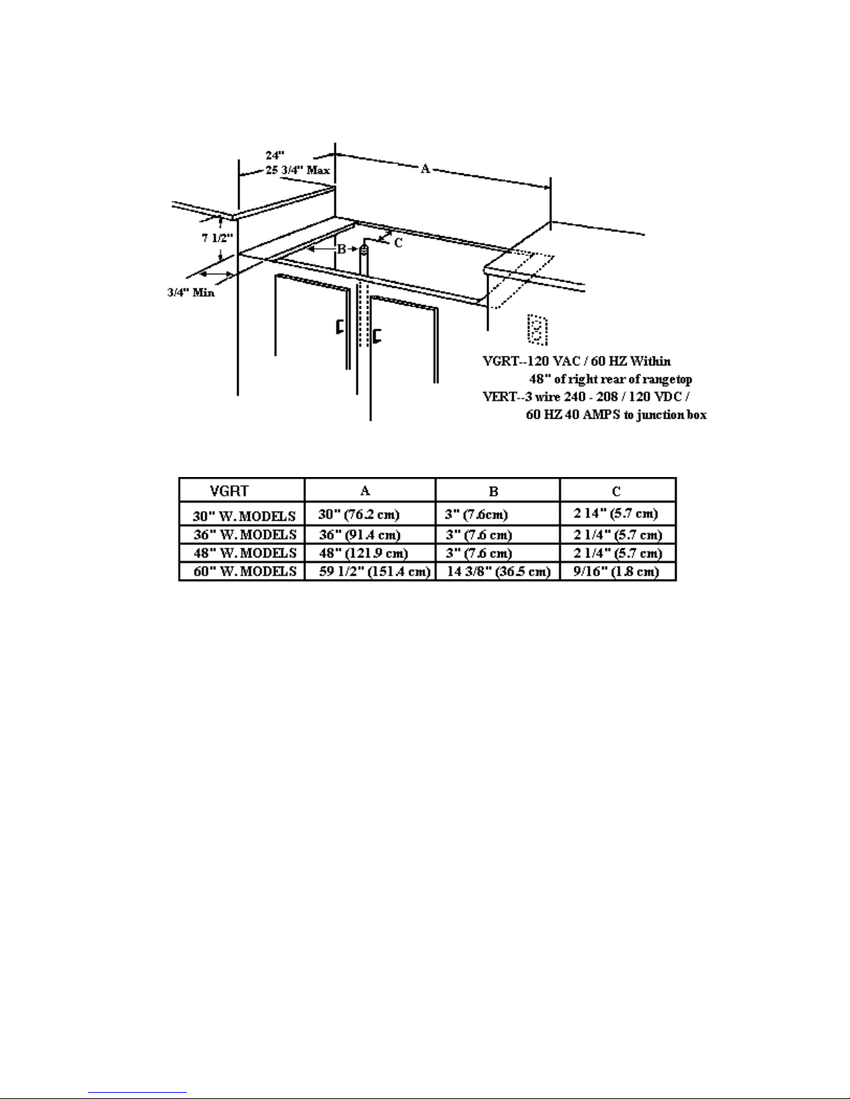
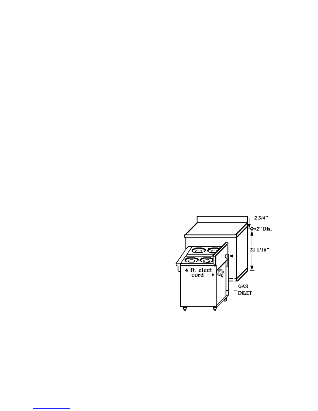
RANGETOP CUTOUT and SPECIFICATIONS
1. Gas Line Requirements:
a. Gas pipe size should be 3/4" (½" inside diameter)
b. Gas pipe should be 3" or less from floor and 6" from left to center of unit to allow for the
flex line.
i.e. 30" range 6"-15" from left 48" range 6"-24" from left
36" range 6"-15" from left 60" range 6"-30" from left
If it is higher than 3" from the floor, the range will not fit flush against the wall and
The shutoff valve will not be accessible.
2. Electrical Requirements: Gas ranges, gas rangetops, and Gas cooktops require a 120 volt
electrical outlet (GFI ground fault outlet not recommended).
a. 3" or less from the floor and 6" from the right to center of the unit.
i.e. 30" range 6"-15" from right 48" range 6"-24" from right
36" range 6"-18" from right 60" range 6"-30" from right
9
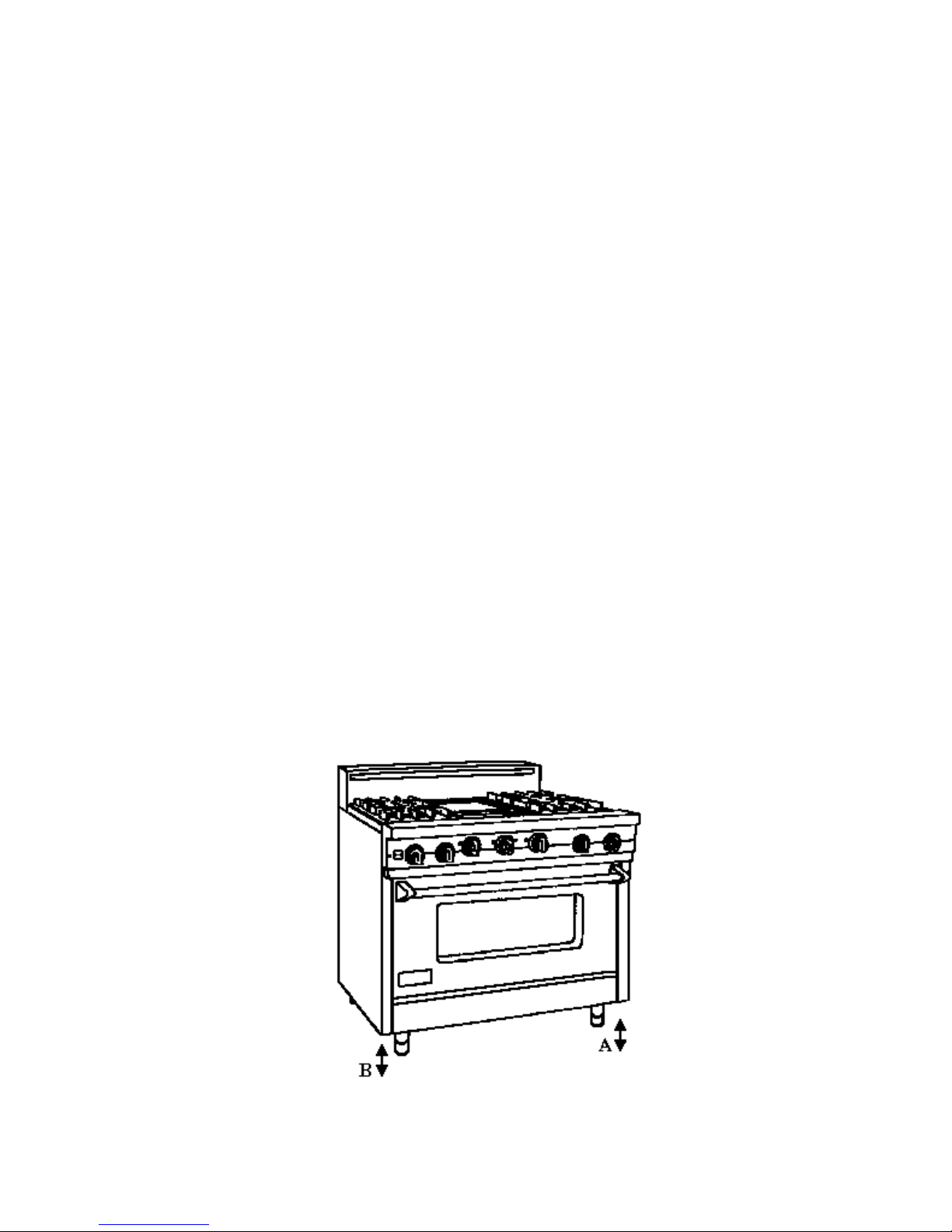
RANGE LEVELING
Careful leveling of the range is critical not only to
performance, but also to allow the alignment of
oven doors and drip tray. Closely follow the
procedures below to ensure proper performance
and appearance of the range. The range being
even slightly out of level will significantly
contribute to misalignment of oven doors.
1. If the floor is smooth and level, level the unit
with the screw thread of the legs. Set the high
corner of the range so that the top of the grate
support is 3/8" above the countertop, and level
the range to the high corner.
2. If the floor is uneven or has a decided slope,
level the unit with metal shims, as the
adjustment required may exceed the thread
available in the leg.
3. Proper and careful leveling of the range is
necessary for proper alignment of the oven
doors.
! The body of the range does n ot have a rigid f rame
to hold it into one position. This non-rigid
framework allows th e range to shift w ith u n-level
floors or slanted cabinets.
! Moving any one of the adjustable leveling leg s u p
or down will shift the range body. Use the
vertical line betw een the edg e of the door an d the
left side trim or center t rim on the 2 door m odels
to adjust the leveling legs.
A. Right Side
Front / Back
Adjusta ble Legs
B. Left Side
Front / Back
Adjusta ble Legs
When adjusted properly this space will be
uniform from the top to the bottom of the
door. The bottom corner of the end panel
will move in or out. Adjust this lower corner
to have an equal space from the top to the
bottom of the door.
! Increasing the length of the right front levelin g
leg will raise the right front corner of the
range, moving the top of the door to the left.
Lowering the right front leveling leg will
cause the top of the door to move to t he rig ht.
! Using the left front leveling leg will give you
the opposite effect. Raising the left front
corner will move the top of the door to the
right. Lowering the corner will move the top
of the door to the left. The rear leveling legs
will also have an effect on th e door alignment.
4. After the range is properly leveled , the drip
tray ha ndle may be aligned by loosening the
screws and a djusting the hand le horizo ntally
within the limits provided by the slotted
screw holes.
5. A carpenters’ spirit level should be placed
across the top of the range and the unit
leveled front-to back, side-to side and
vertically. If it is not level, burner
combustion may be erratic, liquid or semi-
liquid batters will
cook at an angle, and the
unit may not function
efficiently.
10

COMBUSTION OF GAS
A. The Meaning of Combustion
acts with a substance to produce large am ounts of
heat rapidly (and usually light), the process is
called combustion or burning.
B. Requirements for Combustion
needed for combustion to take place are fuel,
oxygen (air) and heat (temperature). All m ust be
present. Take away any one of the three and
burning will stop. Gas ignition temperature is
approximately 1100 - 1200 degrees Fahrenheit.
C. Basic Chemistry of Combustion
of gas is a chemical reaction betw een fuel gas and
oxygen. The basic elements of common fuel
gases are hydrogen (H) and Carbon (C). When
hydrogen burns, water vapor (H2O) is
produced. Complete burning of carbon in fuel
gases form carbon dioxide (C02). Complete
combustion produces harmless carbon dioxide
(C02) and water vapor (H20).
Water is produced as a vapor in the burning of
gas.If the flue products remain hot enough, water
is discharged as vapor to the outside through vent
system. If th e flu e product s shou ld becom e cool ,
as in an air conditioned room, this water vapor
will condense out as a liquid on any cooler
surface. The temperature at which water forms
from vapor is known as the dew-point.
D. Controlled Combustion
takes place when fuel gas and air are
supplied at proper rates to assure complete
combustion (burning) of the gas in a steady flam e.
When a gas appliance is operating
properly, burning starts at the burner ports.
Gas flow is controlled by a gas orifice size and by
gas pressure upstream of the orifice. Burners
which have some air premixed with the gas before
it passes through the B URNER PORTS
are called “blue flame” burn ers. This air added t o
the gas is called primary air. The rest of the air
required for complete combustion is supplied
to the burner flames in the COMBUSTION
CHAMBER and is called SECONDARY AIR.
Adjustments of gas rate and prim ary air prov ide
the key to obtaining stable, blue flames on the
burner using primary air. AIR SHUTTERS or
other devices provide control of primary air.
Proper amounts of prim ary and s econdary air are
needed for quiet and eff icie nt a pplia nce ope ratio n
- When oxygen
- Three things
- Combustion
- Controlled combustion
and for complete combustion of the gas. Size of
the inlet openings and flue outlets control
secondary air flow.
E. Explosive Combustion
very rapid burning which is not under control.
F. Limits of Flammability
mixtures will burn. Mixtures with zero to four
percent natural gas in air are to lean to burn.
Mixtures of four to fourteen percent natural gas in
air can burn with a controlled flame.
Flammability Limits are of interest to those
dealing with problems and everyday ope ratio ns in
the gas industry. For example consider,
FLASHTUBE ignition of rangetop burners. A
gas-air mixture from the burner head passes
through a char ge port into the open e nd of the
flashtube. This mixture is too rich to burn
without secondary air, but some air also enters
the flas htube at the entrance. The additional air
causes the mixture to become leaner to a
composition that is flammable. Wh en t he m ixt ure
travels down the tube to point of ignition, the
flame will carry back from the lighter to the
charge port and light the gas at the burner. If
the mixture in the flashtube has too
much gas (t oo rich) or has too m uch air (t oo le an),
the burner will not light.
Flammability L im its also enter th e picture w hen
primary air adjustm ents are ma de on burner s. For
example, Infra-red (radiant) burners usually
operate with about 100 percent primary air. In
other word the gas air mixture in the bu rn er h ead
contains all the air ideally required for complete
combustion. If too much prim ary air is used, the
mixture may becom e too lean and f all outside the
lower flammability limit and it will not burn on
the burner surface.
Unburned gas should not be allowed to coll ect in
combustion chambers or confined spaces because
gas-air mixture with in the flamm ability li mit s w ill
explode if ignited.
G. Incomplete Combustion - Causes and Effects
To obta in co mple te co mbustio n eno ugh air must
be supplied to the process. This air must have a
Reasonably normal oxygen content. Complete
burning of g as produces harm less carbon dioxide
and water vapor. If not enough air is suppli ed
other products will form. Some of these products
are harmful, especially carbon monoxide.
- An explosion is simply
- Not all air-gas
11
COMBUSTION OF GAS (CONTINUED)
It is vital that an appliance venting system do its
job. The importance of provi ding enough fresh
air to the room in which and appliance is
located can not be stressed too strongly.
Carbon monoxide is a toxic gas. It can cause
death if enough of it is inhaled. This gas has no
odor, color or taste, so that it cannot be detected
by bodily senses. Inhaled carbon monoxide is
absorbed into the blood. It combines with
hemoglobin in the blood to a m uch greater exten t
than oxygen and remains in the blood longer
than oxygen does. In doing so, it acts to reduce
the oxygen- carry ing f uncti on of th e blood. Thus,
a person exposed to carbon mon oxide can die lf a
lack of oxygen.
Carbon monoxide is only one product of
incomplete combustion. AL DEHYDES, another
class of compounds, also may be formed in
incomplete combustion. While carbon monoxide
is odorless, Aldehydes have a s h arp, pen e trat in g
odor. They are readily detected be sm ell, even at
very low concentrations. The odor of aldehydes
differs from odorants added to natu ral gas and the
two should not be confused. The absence of
aldehydes does not as sure t hat carbon m onoxi de
is not present. How ever, if the odor of aldehy des
is present, then carbon monoxides almost always
will be present, aldehydes themselves also are
toxic.
H. GAS BURNER OPERATION
a device to burn gas under control to produce
useful heat.
Primary air is brought into the burner from
outside the appliance at atmosphere pressure.
The gas jet streaming from the orifice draws or
injects primary air into the burner.
PRIMARY AIR:
before the gas leaves a burner port to burn.
SECONDARY AIR:
a burner flame at the point of combustion.
Air which is mixed with gas
Air externally supplied to
- A gas burner is
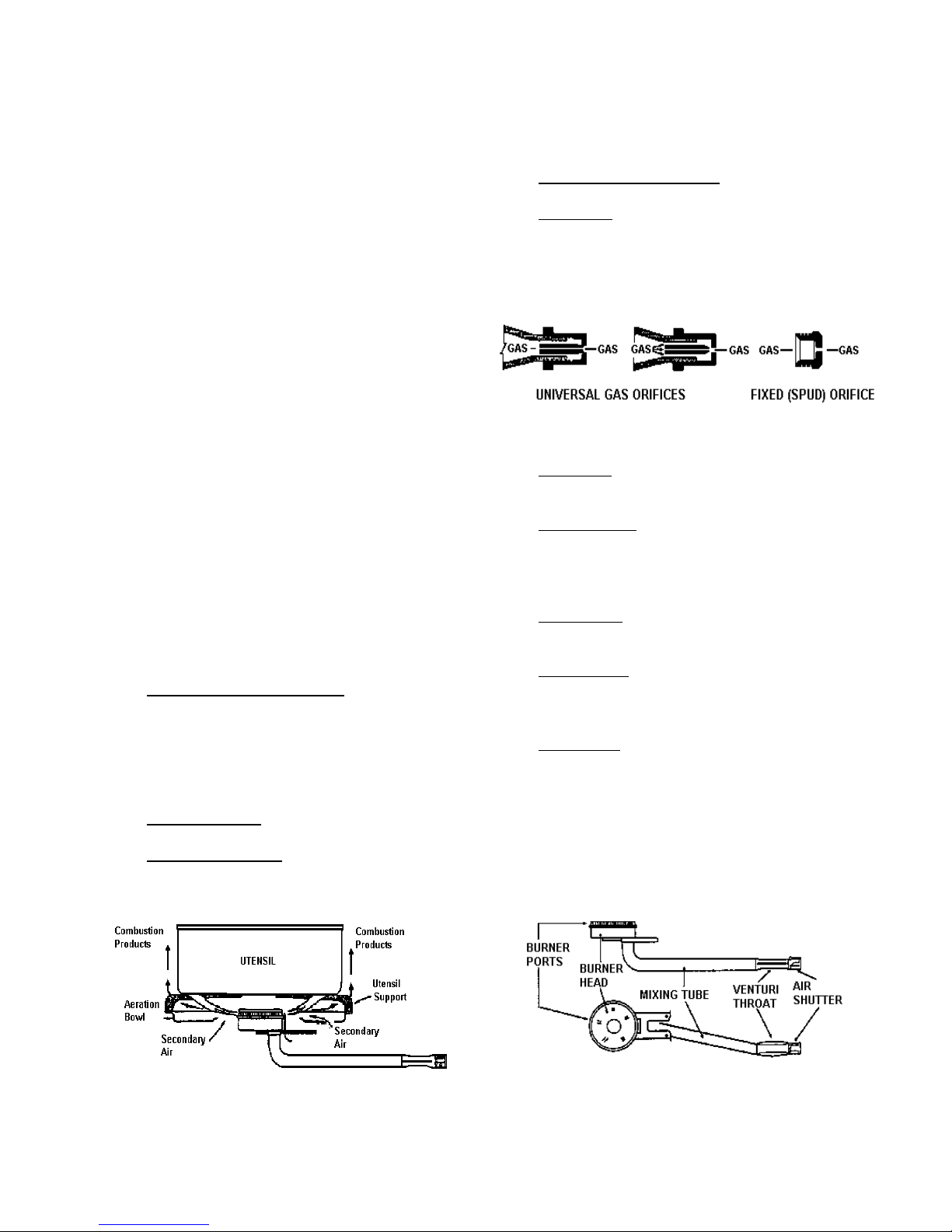
I. BURNER COMPONENTS
Gas Orifice
limits the amount of gas flowing to a burner. Gas
flow rate (volume) depends on the size of the
orifice (hole) and gas pressure at the inlet of the
orifice.
Air Shutter
the openings to control primary air flow.
Venturi Thr oat
body that narrows down and then flares out ag ain .
This neck helps maintain a more constan t prim ary
air injection.
Mixing Tube
from the venturi throat to the burner head.
Burner Head
provides uniform distribution of the air-gas
mixture to those ports.
Burner Ports
heat transfer. They spread the flam es so th ey can
be reached by secondary air. They provide
stable, blue flames.
- An opening o r hole, regulates or
- This is used to adjust the size of
- A section in a pipe or a burner
- Serves to carry the air-gas m ixture
- Contains the burner ports, and
- Distributes f lames to prov ide good
12
 Loading...