

Page 1
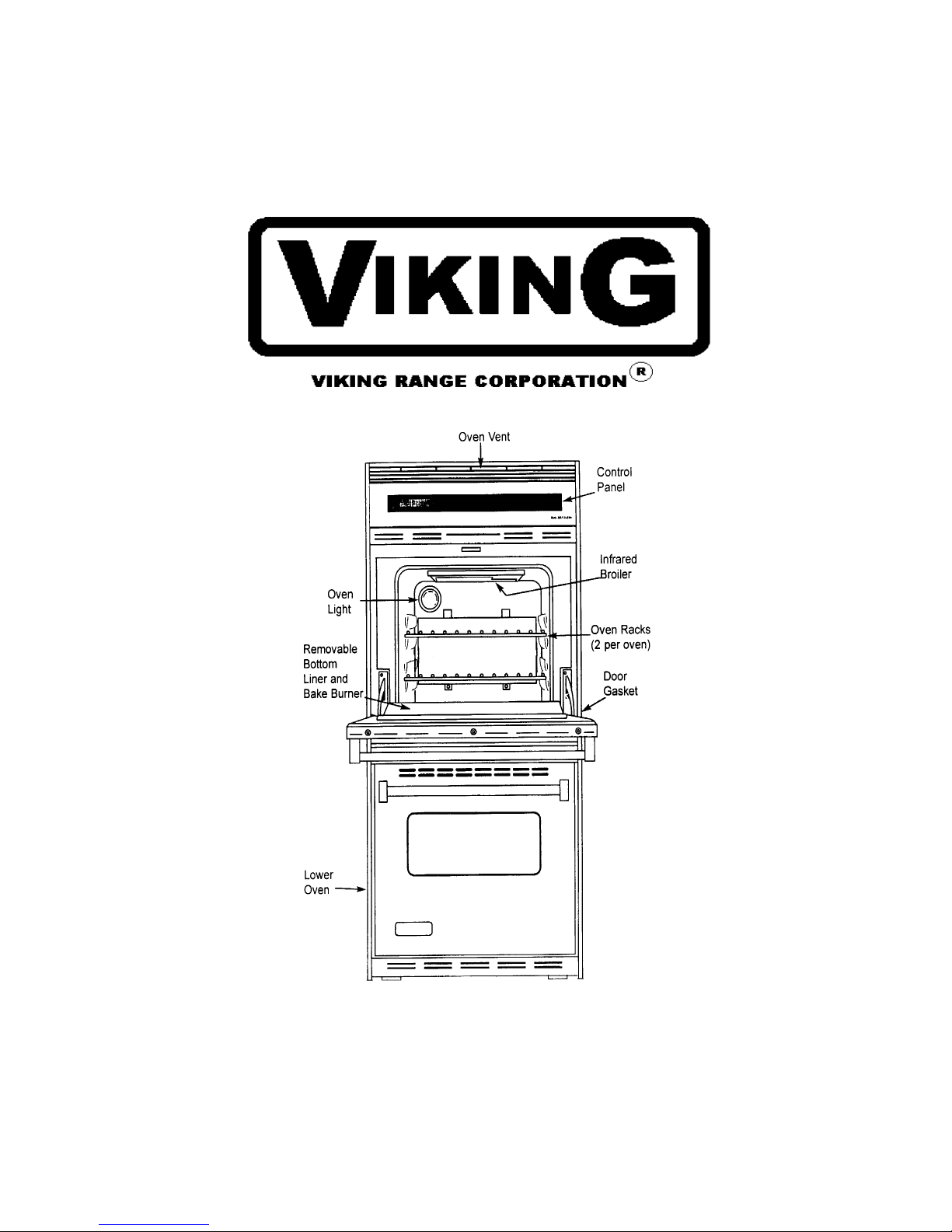
SERVICE NOTEBOOK
GAS WALL OVENS
VGDO271
VIKING RANGE CORPORATION, P. O. DRAWER 956, GREENWOOD, MS. 38930 - USA
Page 2

Table of Contents
Important information......................................... 4
Introduction
General Information....................................... 5
Model number location................................... 5
Important Safety Information
Safety Practices for Servicer......................... 6
Receiving Wall Oven..................................... 7
All Appliances............................................... 7
Self-Cleaning Oven....................................... 7
Oven.............................................................. 7
Delay Ignition.............................................. 7
In Case of Fire............................................... 8
Precautions..................................................... 8
Using the Ovens............................................. 8
Self-Cleaning Oven........................................ 9
Baking, Broiling, and Roasting...................... 9
Connecting Wall Oven to Gas........................ 9
Electrical Requirements............................... 9
Extension Cords.............................................. 9
Grounding........................................................9
Product Safety Devices................................. 10
General Information
Baking Guide................................................ 11
Prepare to Bake .............................................. 11
Remove Items Stored in Oven........................ 11
Oven Racks.................................................... 11
Oven Rack Placement ................................... 11
Bake Pan Placement ....................................... 11
Removing Oven Door .................................... 12
Replacing Oven Light ................................... 12
Care and Cleaning
Cleaning.......................................................... 13
Testing Procedures
Sail Switch...................................................... 14
Vent Hi-Limit Switch...................................... 14
Thermal Fan Switch ....................................... 14
Fan Motors ................................................... 15
Gas Valve ...................................................... 15
Bake and Broil Ignitors ................................. 15
Auto Latch Motor........................................... 16
Auto Latch Switches..................................... 16
Oven Temperature Sensor............................. 16
Oven Temperature Test ................................ 17
Troubleshooting Procedures ............................... 18
Disassembly Procedures
Removing and Replacing Oven ..................... 20
Control Panel Assembly .................................20
ERC (Electronic Range Control)..................... 20
Mylar Control Panel .................................. 21
Transformer / Relay Board(s)........................ 21
Vent Hi-Limit Switch ................................. 21
Thermal Fan Limit Switch .......................... 21
Oven Sensor ................................................ 21
Upper Oven Door Latch / Door
Plunger Light Switch Assembly................... 21
Lower Oven Door Latch / Door
Plunger Light Switch Assembly .................. 22
Oven Light Bulb / Oven Light Socket ......... 22
Oven Liner Removal .................................... 22
Oven Door Removal ..................................... 23
Door Disassembly ........................................ 23
Oven Door Hinge .......................................... 23
Blower Motor ................................................ 23
2
Page 3

Installation
Packing Material....................................... 26
Oven location............................................ 26
Cabinet Opening....................................... 26
Gas and Electrical Supply Location.......... 26
Electrical Connection Requirements......... 26
Gas Connection Requirements.................. 27
Gas Supply Pressure.................................. 28
Seal Wall Openings ...................................... 28
Place Oven in Wall ................................... 28
Converting Pressure Regulator for Use
with Natural Gas or Propane Gas ............. 28
Converting Type 1 Pressure Regulator
for Use with LP / Propane ......................... 29
Gas Connection .......................................... 31
Testing for Gas Leaks ................................. 31
Test Oven Burner Flame ............................. 31
Adjust Oven Burner Flame .......................... 32
Test Broiler Flame ....................................... 32
Removal and Replacement of Oven ............ 32
Programming Instructions
Oven Control ................................................ 33
Display........................................................... 34
Display Glossary ......................................... 34
Oven Signals ................................................. 35
Other Features .............................................. 35
Sounds (Fan)............................................... 35
Quick Reference Instructions ....................... 36
Flashing Display ........................................... 37
Setting Electronic Clock ............................ 37
Setting Electronic Timer ............................... 37
Prepare to Bake, Timed Baking ,
and Delayed Baking ..................................... 37
Table of Contents
Baking ............................................................ 38
Time Baking ................................................. 38
Delayed Baking ............................................ 39
Prepare for Broiling ...................................... 39
Infrared Broiling System .............................. 39
Hold .............................................................. 39
Prepare for Self-Clean and Delayed
Self-Clean Cycle ........................................... 40
Self-Cleaning ................................................ 40
Delayed Self-Clean Cycle ............................ 40
Adjusting Oven Temperature ....................... 41
Service Tones and Codes ..............................41
Testing Procedures
Service Information ...................................... 42
Quick Test Procedure.................................... 42
Electronic Range Control Warnings
and Failure Codes ...................................... 42
Temperature Calibration Offset ..................... 43
Function Switch Connection Check
Procedures .................................................... 43
Transformer / Relay Board 1 ........................ 43
Double Line Break K6 ................................. 43
Bake Relay K4 ............................................ 43
Broil Relay K5 .............................................. 43
Oven Light Relay K10 ................................. 43
Door Lock Relay K3 .................................. 43
Display (Filament) Voltage .......................... 43
Relay Board 2 .............................................. 44
Bake Relay K2 .............................................. 44
Broil Relay K3 .............................................. 44
Door Lock Relay K4 .................................... 44
Component Testing Information ........................ 45
Wiring Schematic ........................................... 51
Wiring Diagram .............................................. 52
3
Page 4
IMPORTANT INFORMATION
Pride and workmanship go into every product to provide our customers with quality products. It is possible,
however, that during its lifetime a product may require service. Products should be serviced only by a
qualified service technician who is familiar with the safety procedures required in the repair and who is
equipped with the proper tools, parts, testing instruments and the appropriate service manual. REVIEW ALL
SERVICE INFORMATION IN THE APPROPRIATE SERVICE MANUAL and TECHNICAL
SHEETS BEFORE BEGINNING REPAIRS.
Important Notice for Consumers and Services
WARNING
To avoid risk of serious injury or death, repairs should not be attempted by unauthorized personnel;
dangerous conditions (such as exposure to electrical shock) may result.
CAUTION
VIKING will not be responsible for any injury or property damage from improper service
procedures. If performing service on your own product, assume responsibility for any personal
injury or property damage which may result.
To locate an authorized servicer, consult the dealer from whom you purchased this product. For
further assistance, call:
Viking Preferred Service
Phone # 601-451-4133
Address your written correspondence to: Viking Preferred Service
111 Front Street
P. O. Drawer 956
Greenwood, MS. 38935-9560
Recognize Safety Symbols, Words, and Labels
Danger-Immediate hazards which WILL result in severe personal injury or death
Warning-Hazards or unsafe practices which COULD result in severe personal injury
or death
CAUTION-Hazards or unsafe practices which COULD result in minor personal
injury or product or property damage.
4
Page 5

INTRODUCTION
General Information
This manual provides basic instructions and
suggestions for handling, installing and
servicing your VIKING gas wall oven.
The directions, information, and warnings in
this manual are developed from experience
with, and careful testing of the product. If the
unit is installed according to the manual, it
will operate properly and will require minimal
servicing. A unit in proper operating order
insures the consumer all the benefits provided
by clean, modern gas cooking.
This manual contains basic information
needed be authorized VIKING service
technicians to install and service VIKING gas
wall ovens. There may be, however, some
parts which need further explanation. Refer to
the owners guide or VIKING maintains a tollfree technical support line to answer questions
from authorized service technicians. The
number is 1-800-467-2665.
Model Identification and Ordering
Replacement Parts.
Unit’s model and manufacturing numbers are
located on its rating label. Rating label is
located on the door frame. It can be seen by
opening the oven door. Before ordering parts,
write down the correct model and
manufacturing numbers from the rating label..
This avoids incorrect shipments and delays.
Please refer to parts catalog when ordering
replacement parts.
5
Page 6
SAFETY INFORMATION
As with all appliances, there are certain rules to
follow for safe operation. Verify everyone who
operates oven is familiar with the operations and
with these precautions. Use appliance only for its
intended purpose as described. Pay close attention
to the safety sections of this manual. Recognize
the safety section be looking for the symbol or the
word safety.
Recognize this symbol as a safety precaution.
If the information in this manual is not followed
exactly, a fire or explosion may result causing
property damage, personal injury or death.
Do not store or use gasoline or other flammable
vapors and liquids in the vicinity of this or any
other appliance.
WHAT TO DO IF YOU SMELL GAS
Extinguish any open flames
Do not try to light any appliance.
Do not touch any electrical switch; do not use
any phone in your building.
Immediately call your gas supplier from a
neighbor’s phone. Follow the gas supplier’s
instructions.
If you cannot reach your gas supplier, call the
local fire department.
Installation and service must be performed by an
authorized installer, service agency or gas
supplier.
SAFETY PRACTICES FOR SERVICER
Safe and satisfactory operation of gas wall ovens
depends upon its design and proper installation.
However, there is one more area of safety to be
considered: SERVICING.
Listed below are some general precautions and safety
practices which should be followed in order to protect
the service technician and consumer during service and
after service has been completed.
To avoid risk of electrical shock, property
damage, personal injury, or death verify wiring is
correct, if components were replaced. Verify
proper and complete operation of unit after
servicing.
This gas appliance contains or produces a
chemical or chemicals which are known to the
state of California to cause cancer, birth
defects, or other reproductive harm. To reduce
the risk from substances in the fuel or from fuel
combustion make sure this appliance is
installed, operated and maintained according to
the instructions in this manual.
Due to the nature of cooking, fires can occur as
a result of overcooking or excessive grease.
1. Gas smell-Extinguish any and all flames and open
windows.
2. Turn gas off-Service wall oven with gas turned
off unless testing requires it.
3. Checking for gas leaks-Never check for leaks
with any kind of open flame. Soap and water
solution should be used for this purpose. Apply
solution to suspected area and watch for air
bubbles which indicates a leak. Correct leaks by
tightening fittings, screws, connections, applying
approved compound, or installing new parts.
4. Using lights-Use a hand flashlight when servicing
wall ovens or checking for gas leaks. Electric
switches should not be operated where leaks are
suspected. This will avoid creating arcing or sparks
which could ignite the gas. If electric lights are
already turned on, they should not be turned off.
5. Do not smoke-Never smoke while servicing gas
wall ovens, especially when working on piping
that contains or has contained gas.
6. Check wall oven when service is completed-
After servicing, make visual checks on electrical
connection, and check for gas leaks. Inform
consumer of the condition of the wall oven
before leaving.
7. Adhere to all local regulations and codes when
performing service.
6
Page 7

SAFETY INFORMATION
RECEIVING WALL OVEN
Installer needs to show consumer location of the wall
oven gas shut-off valve and how to shut it off, if
necessary.
Authorized servicer must install the wall oven in
accordance with the installation instructions.
Adjustments and service should be performed only
by authorized servicer.
Plug wall oven into a 120-volt grounded outlet only.
Do not remove round grounding prong from the plug.
If in doubt about grounding of the home electrical
system, it is consumers responsibility and obligation
to have an ungrounded outlet replaced with a
properly grounded three-prong outlet in accordance
with the National Electrical Code. Do not use an
extension cord with this appliance.
Insure all packing materials are removed from the
wall oven before operating it, to prevent fire or
smoke damage should the packing material ignite.
Ensure wall oven is correctly adjusted by a qualified
service technician or installer for the type gas (NAT
or LP). Some wall ovens can be converted for use
with NAT or LP gas.
With prolonged use of a wall oven, high floor
temperatures could result. Many floor coverings will
not be able to withstand this kind of use. Never
install wall oven over vinyl tile or linoleum that
cannot withstand high temperatures. Never install
wall oven directly over carpeting.
ALL APPLIANCES
1. Proper Installation--Be sure your appliance is
properly installed and grounded by a qualified
technician.
2. Never Use Appliance for Warming or Heating the
Room.
3. Do Not Leave Children Alone-- Children should not
be left alone or unattended in the area where the
appliance is in use. They should never be allowed
to sit or stand on any part of the appliance.
4. Wear Proper Apparel--Loose fitting or hanging
garments should never be worn while using
appliance.
5. User Servicing--Do not repair or replace any part of
the appliance unless specifically recommended in
the manual. All other servicing should be referred
to a qualified technician.
6. Storage in or on Appliance--Flammable materials
should not be stored in oven.
7. Do Not Use Water on Grease Fires-- Smother fire or
flame, or use dry chemical or foam-type
extinguisher.
8. Use Only Dry Potholders--Moist or damp
potholders on hot surfaces may result in burns from
steam. Do not let potholder touch burners. Do not
use a towel or other bulky cloth.
SELF-CLEANING OVENS
1. Do Not Clean Door Gasket--The door gasket is
essential for a good seal. Care should be taken not
to rub, damage, or move the gasket.
2. Do Not Use Oven Cleaners--No commercial oven
cleaner or oven liner protective coating of any kind
should be used in or around any part of the liner.
3. Clean Only Parts Listed in Manual. See Cleaning
section.
4. Before Self-Cleaning the Oven--Remove broiler
pan, oven racks, and other utensils.
5. Remove all items from oven top and backguard.
OVEN
1. Use Care When Opening Door--Let hot air or steam
escape before removing or replacing food.
2. Do Not Heat Unopened Food Containers--Build-up
of pressure may cause container to burst and result
in injury.
3. Keep Oven Vent Ducts Unobstructed.
4. Placement of Oven Racks--Always place oven racks
in desired location while oven is cool. If rack is
removed while oven is hot, do not let potholder
contact hot heating element in oven.
DELAYED IGNITION
Bake Burner Flame
Allow no more than 40-60 seconds before burner
ignites and heat is felt. To check for heat, open oven
door to first stop and place hand over oven door. If
heat is not felt, cancel bake function. If burner
repeatedly fails to ignite, contact an authorized servicer.
Broiler Flame
Allow no more than 40-60 seconds before burner
ignites and flame is seen. If burner does not ignite
cancel broil function. If burner repeatedly fails to ignite
within 40-60 seconds contact an authorized servicer.
Radiant screen style broiler flame should appear hazy
or fuzzy. Haze should be no more than 3/8 inch thick.
The radiant screen should begin to glow red within 1-2
minutes.
7
Page 8
SAFETY INFORMATION
IN CASE OF FIRE
Fires can occur as a result of over cooking or excessive
grease. Though a fire is unlikely, if one occurs,
proceed as follows:
OVEN FIRES
1. If you see smoke from oven, do not open oven door.
2. Turn oven control to OFF.
3. As an added precaution, turn off gas supply and
power at main circuit breaker, or fuse box.
4. Turn on vent to remove smoke.
5. Allow food or grease to burn itself out in oven.
6. If smoke and fire persist, call fire department.
7. If there is any damage to components, call repair
service before using oven.
If smoke or fire persists call the local fire
department.
To avoid the risk of property damage or personal injury
do not obstruct the flow of combustion or ventilation air
to the oven.
To avoid the risk of electrical shock, serious personal
injury or death: Make sure your oven has been properly
grounded and always disconnect the electrical supply
before servicing this unit.
NOTE: The maximum gas supply pressure for these
models must not exceed 14 inches W.C.P.
PRECAUTIONS
Do not mix household cleaning products. Chemical
mixtures may interact with objectionable or even
hazardous results.
Do not put plastic items on warm cooking areas.
They may stick and melt.
Do not use damp sponge or dishcloth to clean oven
when oven is hot. Steam from sponge or dishcloth
can burn.
Do not leave fat heating unless you remain nearby.
Fat can ignite if overheated by spilling onto hot
surfaces.
USING THE OVEN
Do not leave children alone or unattended where a
wall oven is hot or in operation. They could be
seriously burned.
Do not allow anyone to climb, stand or hang on the
door. They could damage the wall oven and cause
severe personal injury.
Wear proper apparel. Loose fitting or hanging
garments should never be worn when using oven.
Flammable material could ignite if brought in
contact with flame or hot oven surfaces which may
cause severe burns.
Never use wall oven for warming or heating a room.
This may cause burns, injuries or a fire.
Do not use water on grease fires
Do not let grease or other flammable material
collect in or around wall oven.
Do not repair or replace any part of wall oven
yourself unless it is recommended in this manual.
Use only dry potholders. Moist or damp potholders
used on hot surfaces may result in a burn from
steam. Do not let a potholder touch the flame. Do
not use a towel or a bulky cloth as a potholder.
Never leave wall oven unattended while cooking.
Boilovers can cause smoking and may ignite.
Only certain types of glass/ceramic, earthenware, or
other glazed utensils are suitable for oven use.
Unsuitable utensils may break due to sudden
temperature change.
Use care when opening oven door. Let hot air or
steam escape before removing or replacing food.
Do not heat unopened food containers in oven.
Buildup of pressure may cause a container to burst and
result in injury.
Keep wall oven vent ducts unobstructed.
Place oven racks in desired location while oven is
cool. If a rack must be moved while oven is hot,
use a dry potholder.
Do not use aluminum foil to line oven bottom or
racks. Aluminum foil can cause a fire and will
seriously affect baking results.
Do not touch interior surfaces of oven during or
immediately after use. Do not let clothing or other
flammable materials come in contact with bake or
broil burners.
Other areas of the oven can become hot enough to
cause burns, such as vent openings, window, oven
door and oven racks.
To avoid steam burns, do not use a wet sponge or
cloth to wipe up spills on hot cooking area.
Do not store combustible or flammable materials
such as gasoline or other flammable vapors and
liquids near or in oven.
Do not clean oven gasket located on back of the
door. Gasket is necessary to seal the oven and can
be damaged as a result of rubbing or being moved.
Do not drape towels or any material on oven door
handles. These items may ignite causing a fire.
Do not store items of interest to children in cabinets
above wall oven. Children may climb on oven to reach
these items and become seriously injured.
8
Page 9
SAFETY INFORMATION
SELF-CLEANING OVEN
Do not clean door gasket. Door gasket is essential
for a good seal. Be careful not to rub, damage or
move it.
Do not use oven cleaners. No commercial oven
cleaner or oven liner protective coating of any kind
should be used in or around any part of the oven.
Remove the broiler pan and other cookware before
self-cleaning oven.
BAKING, BROILING, AND ROASTING
Do not use oven area for storage.
Stand back from wall oven when opening door of a
hot oven. Hot air or steam can cause burns to
hands, face, and eyes.
Do not use aluminum foil anywhere in the oven.
This could result in a fire hazard and damage the
wall oven.
Use only glass cookware appropriate for use in gas
ovens.
Always remove broiler pan from oven when
finished broiling. Grease left in pan can catch fire if
oven is used without removing grease from the
broiler pan.
When broiling, meat that is close to the flame, may
ignite. Trim any excess fat to help prevent
excessive flare-ups.
Make sure broiler pan is placed correctly to reduce
any possibility of grease fires.
Should a grease fire occur in the broiler pan, turn off
oven, and keep oven door closed until fire burns out.
CONNECTING WALL OVEN TO GAS
Install manual shut-off valve in gas line for easy
accessibility outside wall oven. Be sure of the location
of the shut-off valve.
ELECTRICAL REQUIREMENTS
120-volt, 60 Hertz, individual circuit which is properly
grounded and protected by a circuit breaker or fuse.
EXTENSION CORD
Due to possible pinching during installation, extension
cords should not be used on built-in products.
GROUNDING
NOTE: This appliance must be properly grounded, for
personal safety.
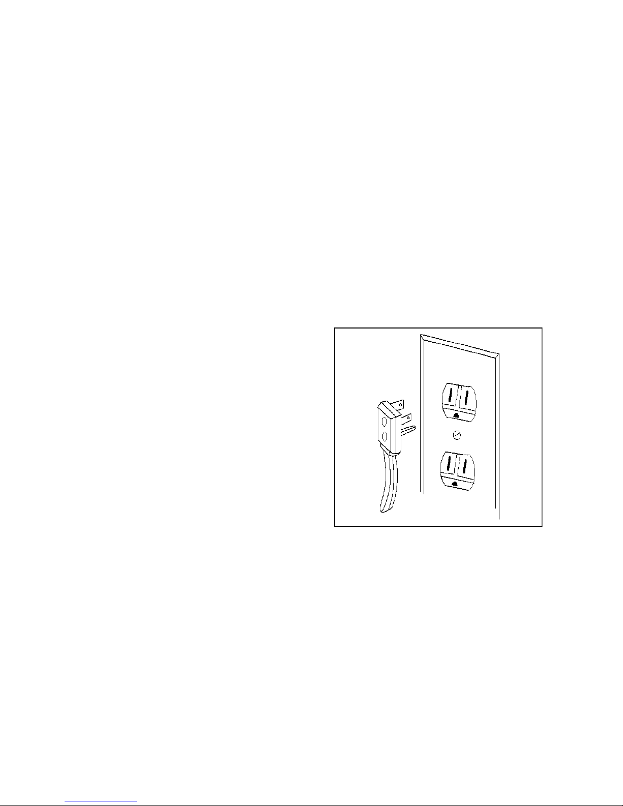
Power cord on this appliance is equipped with a three
prong grounding plug. This matches standard three
prong grounding wall receptacle to prevent possibility
of electric shock from the appliance.
Consumer should have wall receptacle and circuit
checked by qualified electrician to verify receptacle is
properly grounded.
Where standard two prong wall receptacle is
encountered, it is consumers responsibility and
obligation to have it replaced with a properly grounded
three prong wall receptacle.
DO NOT, UNDER ANY CIRCUMSTANCES, CUT
OR REMOVE THE THIRD (GROUND) PRONG
FROM POWER CORD.
9
Page 10

SAFETY INFORMATION
PRODUCT SAFETY DEVICES
Safety devices and features have been engineered into the product to protect consumer and servicer. Safety devices must
never be removed, bypassed, or altered in such a manner as to defeat the purpose for which they were intended.
Listed below are various safety devices together with reason each device is incorporated in the gas wall oven.
Pressure Regulator Maintains proper and steady gas pressure for operation of wall oven controls.
Regulator must be set for the type of gas being used whether Natural or LP. After servicing
regulator, make certain it is set properly before completing service.
Gas Burner Orifice Universal orifices are used on some oven valves. They must be adjusted or set for
type of gas being used, Natural or LP. If not universal orifice, the orifice spud or
hood must be of proper size for gas used.
After servicing a valve or orifice verify it is adjusted properly before completing
service.
Oven Safety Valve Oven valve is designed to be a safety valve. Two basic designs are used in gas wall
ovens.
Hydraulic type valve
Electric type valve
Both types are safety valves because they are indirectly operated by the oven
thermostat, which controls a pilot flame or electric ignitor, to open the oven valve.
Incoming gas pressure closes the valve.
Latch Assembly Locks the door during self-cleaning cycle. Prevents possible injury to consumer by
preventing door opening at high temperatures where ignition of soil could take place
with the in-rush of air.
Grounded Wall Oven Frame Ground prong on power cord is connected to the frame, usually a green lead fastened
by a screw. In addition, any part or component capable of conducting an electrical
current is grounded by its mounting.
If any ground wire, screw, strap, nut, etc. is removed for service, or any reason, it
must be reconnected to its original position with original fastener before the
appliance is put into operation again.
Failure to do so can create a possible shock hazard.
10
Page 11
GENERAL INFORMATION
Baking Guide
Refer to owners manual for following recommendations
only as a guide for times and temperature. Times, rack
position, and temperatures may vary depending on
conditions and food type. For best results, always
check food at minimum time. When roasting, choose
rack position based on size of food item.
Prepare to Bake
To reduce risk of food poisoning due to bacterial
growth and production of toxins, keep meat, milk, fish,
and eggs
refrigerated until needed.
Remove Items Stored in Oven
Remove any pans and other cooking utensils stored in
oven.
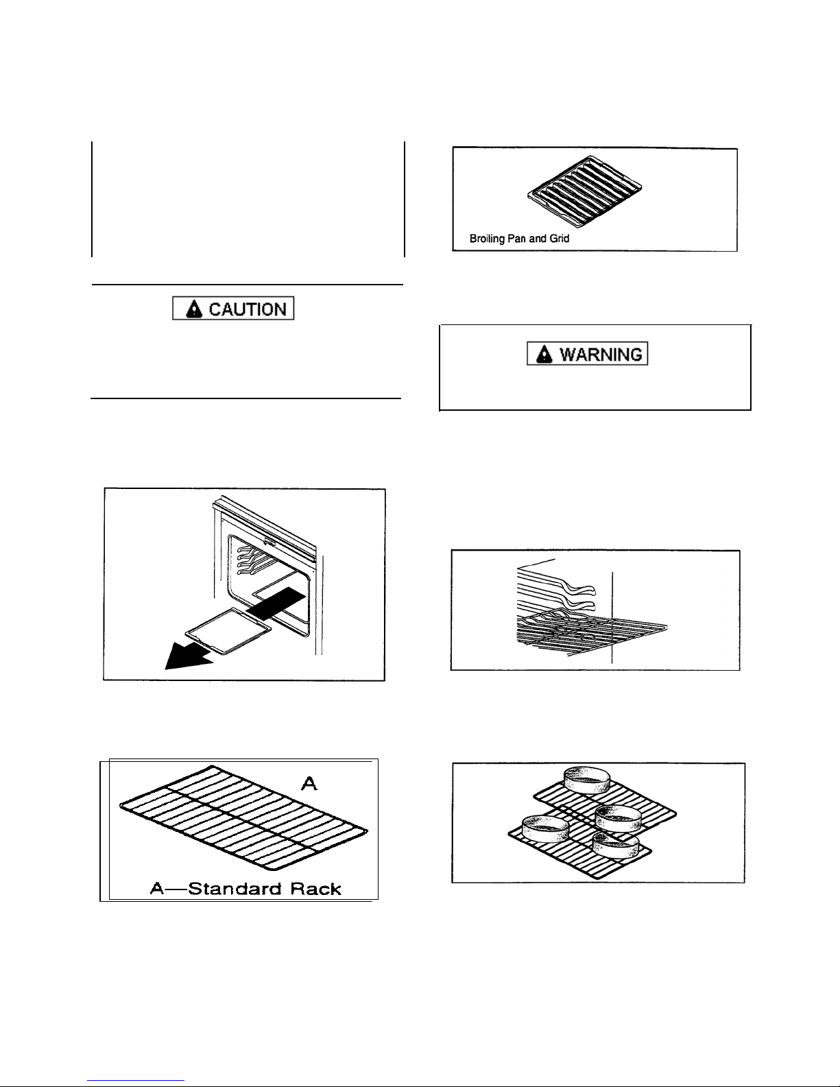
Oven Racks
Oven Rack Placement
Position oven rack before turning oven on.
To avoid damaging oven liner or creating fire, do not
line oven bottom or racks with foil.
1. Pull rack forward to stop position.
2. Raise front edge of rack and pull until rack is out of
oven.
3. Place rack in new rack position.
• Curved edge of rack must be toward rear of
oven.
Bake Pan Placement
Use Standard rack for normal baking and broiling.
• Keep pans and baking sheets 2 “ from oven walls.
• Stagger pans placed on different racks so one is not
directly over the other.
11
Page 12
GENERAL INFORMATION
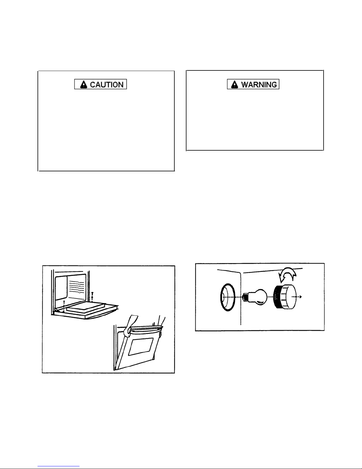
Removing Oven Door
Replacing Oven Light
To avoid personal injury or property damage, handle
oven door with care.
• Door is heavy and can be damaged if dropped.
• Avoid placing hands in hinge area when door is
removed. Hinge can snap closed and pinch hands.
• Do not scratch or chip glass, or twist door. Glass
may break suddenly.
• Replace door glass if damaged.
• Do not lift door by handle.
1. Open door fully.
2. Remove screws.
• Oven doors are attached with a screw on each
side of oven door.
3. Close door to first stop, grasp door firmly on each
side, and lift upward until door is off hinges.
• Do not lift door by handle. Glass or handle can
break.
• Only push hinges closed once oven door is
removed if necessary. Use both hands when
closing hinge. Hinge snaps closed.
To avoid risk of burns or electrical shock, disconnect
electrical supply to oven before changing light bulb.
• Before replacing light bulb make sure bulb and lens
are cool.
• Wear protective gloves.
• Do not operate oven without bulb and lens cover in
place.
1. Disconnect electrical supply.
2. Remove oven door if desired.
3. Unscrew light bulb cover (counterclockwise)
located in rear of cavity. Then turn light bulb
counter-clock-wise to remove.
4. Replace light bulb with 120-volt, 40 watt appliance
bulb.
• Do not over-tighten bulb or cover. They may be
difficult to remove later.
5. Replace light bulb cover and oven door before use.
6. Reconnect power supply.
12
Page 13
CARE AND CLEANING
Cleaning
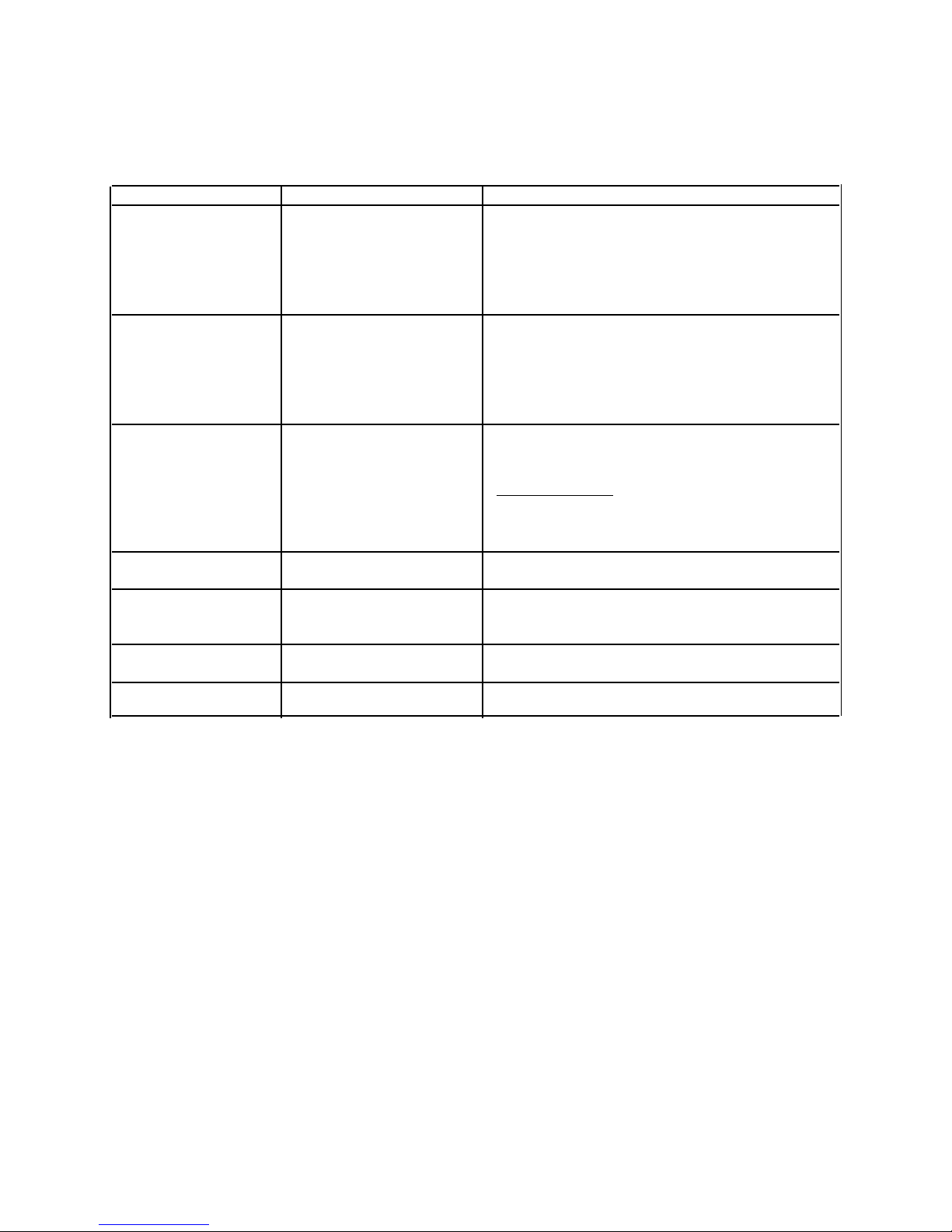
Part Material to Use General Directions
Clean burner area Soap and a non-abrasive 1. Pull oven bottom forward and lift out.
plastic scouring pad, cloth 2. Unscrew nut on burner and remove burner baffle.
or toothbrush. 3. Wipe out burner area around burner with cloth
and warm soapy water.
4. Dry area thoroughly. Replace burner baffle and
Broiler pan and grid Soap and a non-abrasive Drain fat, cool pan and grid slightly.(Do not let soiled
plastic scouring pad, cloth pan and grid stand in oven to cool.) Sprinkle with soap.
or toothbrush. Fill the pan with warm water. Let pan and grid stand for
Inside oven door Soap and water Clean the outside of the door and the window area with
Outside finish Soap and water Wash all glass with cloth dampened in soapy water.
Oven interior surfaces Soap and water Cool before cleaning. Frequent wiping with mild soap
Control panel Soap and water Wash with cloth dampened in soapy water.
Oven racks Soap and water For heavy soil, clean by hand and rinse thoroughly.
oven bottom.
a few minutes. Wash or scour if necessary. Rinse and
dry. The broiler pan and grid may also be cleaned in
the dishwasher.
warm soapy water.
Oven Door Gasket
Do not clean the braided oven door gasket. Gasket should
not be moved while cleaning. Avoid getting any cleaning
materials on gasket.
Rinse and polish with a dry cloth.
and water prolongs time between self-cleaning.
Be sure to rinse thoroughly.
Rinse and polish with a dry cloth.
13
Page 14

T EST PROCEDURES
To avoid the risk of electrical shock, personal injury or death, disconnect power
before servicing, unless testing requires it.
Control compartment tests generally requires removal
of oven from cabinet cutout. See disassembly
instructions to access control compartment.
Sail Switch
Sail switches are located in the rear of control
compartment and mounted to control compartment
back, in front of the fan motors. During self-clean
operations thermal switch contacts close, supplying
power to fan motors. Air from the fan motor pushes
against the sail switch paddle, closing the sail switch
contacts, supplying power to the self-clean circuit. The
sail switch contacts must close for proper self-clean
operation.
Use the following procedure to check sail switch
contacts
for continuity.
1. Disconnect power from oven. Disconnect switch
wires.
2. Access sail switches by removing control panel
assembly.
3. Set ohmmeter in the low ohm range. Attach meter
leads to switch terminals on sail switch.
4. Meter should indicate no continuity or infinite ohms
when switch is in normal position.
5. Push switch paddle to close switch contacts. Meter
should indicate continuity or a low ohm reading.
6. Replace sail switch that failed the test.
NOTE: Both sail switches must be tested.
Vent Hi-Limit Control
OPEN CLOSED
145°F 185°F
1. Turn off power to
oven and disconnect gas
supply.
2. Remove oven from
wall cutout.
3. Remove screws securing outer cabinet top shield to
outer cabinet wrapper shield.
4. Disconnect wires from switch connections.
5. Attach ohmmeter leads to switch terminals. At
ambient room temperature 70°F, continuity
should be indicated.
Thermal Fan Switch
Thermal fan switches are mounted behind the control
panel. Fan switches monitor the temperature at the rear
of the oven cabinet and supply power to the fan motor
if the rear cabinet temperatures exceed 150°F.
Thermal fan switch contains three terminals. Terminal
1 is the common terminal connected to the power
source. Terminal 2 is the NO terminal connected to the
fan motors and terminal 3 is the NC terminal connected
to the oven elements.
During most cooking operations, the C-NC contacts
remain closed. When the oven rear cabinet
temperatures reach approximately 150°F, contacts CNC open and C-NO closes supplying power to the fan
motors. Use the following procedure to check contacts
C-NC for continuity.
1. Disconnect power to oven. Remove switch wiring.
2. Access thermal fan switches by removing the oven
from the cabinet and rear cabinet back panels
3. Set ohmmeter to low range.
4. Attach meter leads to switch terminal 1 or Com and
3 to NC.
5. Meter should indicate low ohms or continuity. It is
difficult to check fan switch contacts COM-NO
since they are closed when the rear cabinet
temperature reaches 150°F and above.
Terminals 1-2 (NO) closed @150°F open @ 120°F
Terminals 1-3 (NC) opened @150°F closed @ 120°F
14
Page 15
T EST PROCEDURES
To avoid the risk of electrical shock, personal injury or death, disconnect power
before servicing, unless testing requires it.
Fan Motors
The fan motors are mounted to the control compartment back.
They cool the exterior oven cabinets, electrical components
and close the sail switch contacts during self-clean operation.
Use the following procedure to check for continuity.
1. Remove oven from cabinet. Remove cabinet top.
2. Disconnect power from oven. Remove motor wiring.
3. Set ohmmeter to low range.
4. Attach meter leads to wiring terminals. Meter should
indicate a low resistance reading of approximately 20 - 30
ohms for continuity.
5. If an open circuit is indicated, the motor coil has
failed. Replace motor.
6. Test each terminal to ground. If motor cavity is
shorted, replace motor.
Gas Valve
The bake and broil dual gas valves supply gas to the bake and
broil burners. The valves contain bimetal arms attached to
the valve seats held closed by incoming gas pressure. These
arms are wrapped with a small electric heater coil. When a
current range of approximately 3.2-3.6 amps flows through
the bake or broil circuit, the bimetal arm is heated. Heating
causes the arm to bend, allowing gas to flow and be ignited
be the burner ignitor.
The broil gas valve is located on the right side of the control
panel flueway and the bake gas valve is located on the left
side of the control panel flueway.
The bimetal arms can be checked for continuity using the
following procedure.
1. Access valves by removing control panel glass and
control panel mounting bracket.
2. Disconnect power to oven. Remove gas valve wiring.
3. Set ohmmeter to low ohms range. Attach meter leads to
the two gas valve terminals facing rear of oven.
4. Meter should indicate low ohms or continuity.
5. Repeat on two gas valve terminals facing front of
oven.
6. If meter indicates infinite ohms, an open heater coil,
the complete gas valve must be replaced.
NOTE: Do not apply 120 VAC to valve. Apply 120 VAC to
valve will render valve inoperative.
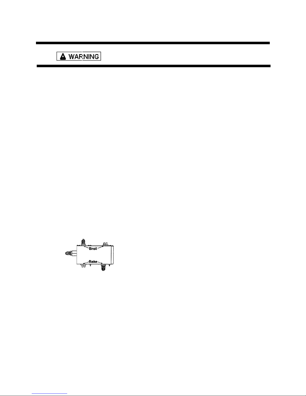
Bake and Broil Ignitors
The bake and broil ignitors are mounted to the bake and broil
burners. They ignite the gas flowing into the burner.
During bake and broil operations, current flows through the
ignitor, gas valve and thermostat at neutral. As the ignitor
heats up and starts glowing, its internal resistance decreased.
This allows more current to flow through the bake or broil
circuit.
When the circuit current reaches approximately 3.2-3.6 amps,
the bimetal arm in the gas valve flexes, opening the valve and
allows gas to flow to the burner where it is ignited by the
glowing ignitor. The ignitors glow anytime the bake or broil
burners are operating and cycles on and off with the
temperature setting.
Use the following procedure to check the ignitors for
continuity.
1. Disconnect power to oven.
2. Remove ignitor from burner.Disconnect ignitor
wiring.
3. Set ohmmeter R X 10 range. Attach one meter lead to
each ignitor lead.
4. A resistance of several hundred ohms may be indicated.
Amount of resistance may vary with each ignitor. This
test determines if ignitor is opened internally.
5. Ignitor may still have to be replaced even though
continuity is indicated and it glows when the oven is set
for a bake, broil or clean function.
Ignitor current may be measured more exactly by testing
with the oven operating. Use the following procedure to
test the ignitor current with the oven operating.
1. Insert an ammeter in series with one lead of ignitor or any
amprobe attached to the lead to check amount of current
flowing through the ignitor circuit.
2. Turn on oven and wait for ignitor to glow red. Meter
should indicate approximately 3.2-3.6 amps.
The same procedure may be use to bench test the ignitor.
Connect an AC jumper or test cord to the ignitor leads
follow the preceding procedure.
and
15
Page 16

T EST PROCEDURES
To avoid the risk of electrical shock, personal injury or death, disconnect power
before servicing, unless testing requires it.
Auto Latch Motor
Do not
assembly. If latch motor or switches have failed,
replace latch assembly.
1. Disconnect power.
2. Slide oven out from wall cutout approximately 6
inches to gain access to control panel screws.
3. Remove screws securing control panel to unit, and
pull control panel out of unit to gain access to latch
assembly.
4. Disconnect lead wires from latch motor.
5. Connect jumper cord leads to latch motor.
6. Connect jumper cord to 120 AC power source.
7. Replace if latch motor fails to operate.
8. Reverse procedure to reconnect.
Auto Latch Switches
Unlock and lock door latch switches cannot be
replaced.
Replace latch as an assembly.
1. Perform steps 1 through 3, from “Auto Latch
2. Disconnect lead wires from door latch switch
3. Set ohmmeter to the R X 1 scale.
4. Attach meter leads to door latch switch (unlock).
5. Depress actuator arm. The meter should read
continuity.
6. Reverse procedure to reconnect.
7. Use same procedure to test door latch switch (lock).
If upper latch fails in the closed position.
remove latch motor or switches from latch
Motor”.
(unlock)
1. Shut off electricity at the fuse box or circuit breaker.
2. Remove control panel to gain access to latch
assembly.
3. Force door latch rod past “fishhook” detent.
4. Replace latch assembly.
Oven Temperature Sensor
Detail testing can be accomplished as follows.
Oven temperature sensor is mounted in the oven cavity
and electrically connected to the ERC.
Following is approximate resistance.
75°F--1082 ohms
350°F--1656 ohms
550°F--2056 ohms
880°F--2686 ohms
Sensor resistance can be checked by removing the
sensor interconnect harness plug from the ERC and
inserting ohmmeter leads into the harness connector
plug. A resistance reading of approximately 1100 ohms
should be indicated at ambient room temperature, 75°F.
If a higher resistance is indicated, then remove sensor
from oven. Disconnect sensor from harness at plug and
recheck sensor resistance to assure that the problem is
in the sensor and not in the interconnect harness or due
to a bad connection.
NOTE: Sensor resistance will increase if held in your
hand.
1. Disconnect power to oven.
2. Disconnect sensor harness plug from ERC.
3. Connect meter leads into harness connector plug,
resistance should be approximately 1100 ohms at room
temperature 75°F.
• If a higher resistance is indicated remove sensor
from oven. Disconnect sensor from harness at the
plug and recheck sensor resistance to assure the
problem is in the sensor and not in the
interconnecting harness or due to a bad
connection.
16
Page 17
T EST PROCEDURES
To avoid the risk of electrical shock, personal injury or death, disconnect power
before servicing, unless testing requires it.
Oven Temperature Test
The following procedure should be used to verify oven
temperature calibration.
• Verify oven door is adjusted and sealing properly.
• Do not cover the oven racks or oven bottom with
foil.
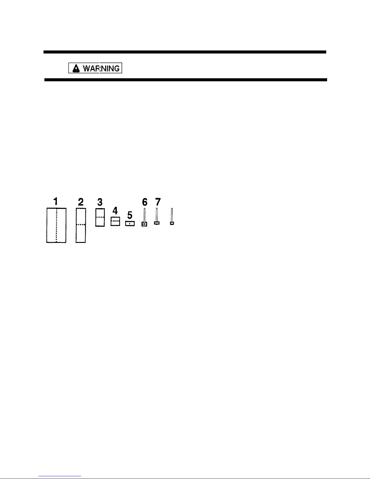
1. Acquire an 8-1/2 X 11 inch piece of aluminum foil.
2. Fold the aluminum foil five times, doubling the
thickness with each fold.
3. After the fifth fold, place the thermocouple tip into
the center of the foil and fold foil over the
thermocouple. Fold ends of the foil sides to attach
foil to thermocouple.
4. Place the oven rack in the center of the oven cavity.
Position thermocouple on the center of the rack.
5. Turn oven to 350°F and allow oven to cycle for 25
to 30 minutes. Oven should cycle between 330°F to
370°F.
17
Page 18
T EST PROCEDURES
To avoid the risk of electrical shock, personal injury or death, disconnect power
before servicing, unless testing requires it.
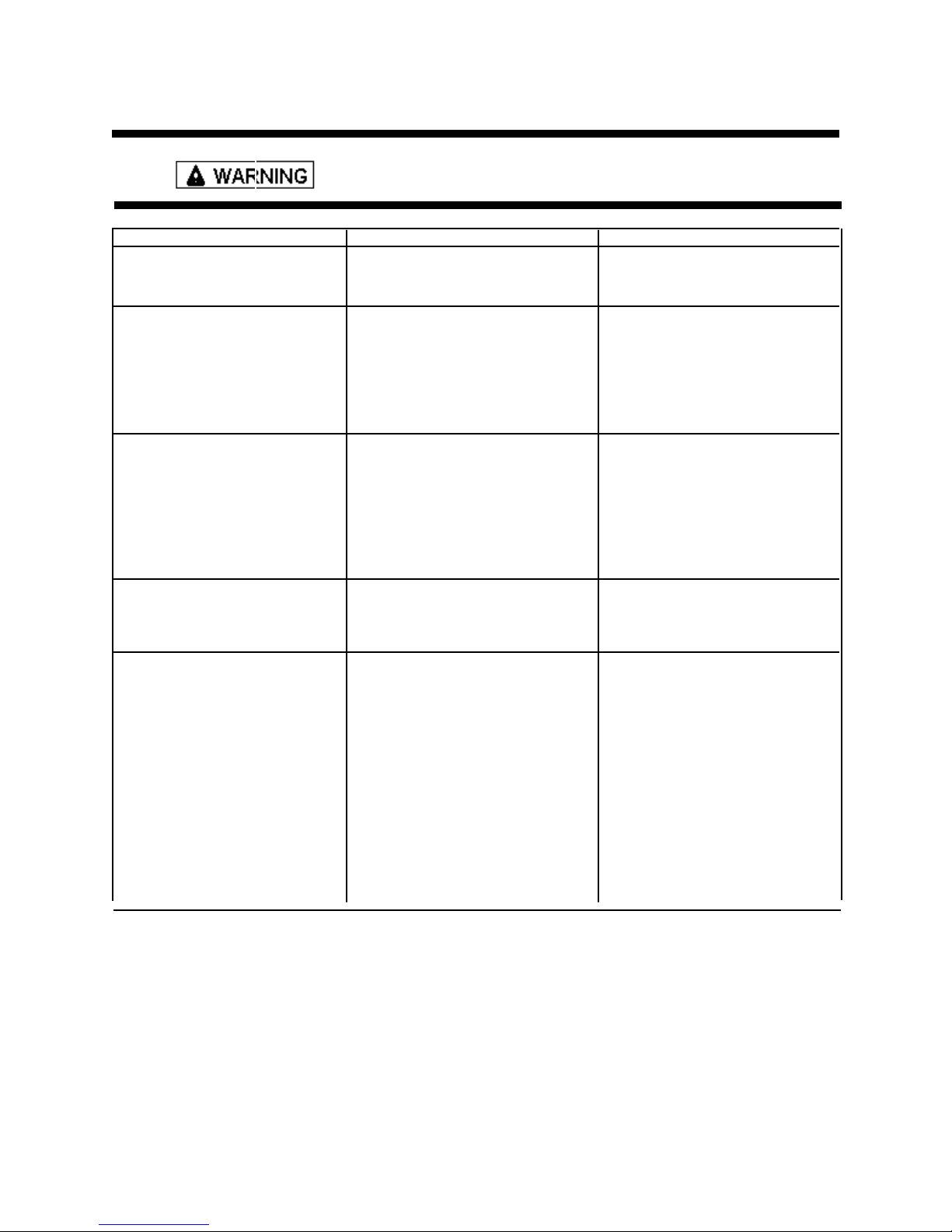
1. No oven operation in bake or A. No voltage to ERC A. Check for 120 VAC at ERC
broil. If no voltage is present, check
2. No gas flows to burner, Ignitor A. Failed ignitor A. Check ignitor current draw.
glows red. Replace ignitor if it fails test.
3. Gas flows to bake/broil A. Ignitor positioned too far from A. Reposition ignitor closer to
burner, but does not light.
4. Broil burner shuts off shortly A. Sail switch contacts not closing. A. Check both sail switch contacts
after the start of self-clean for continuity.
operation. Bake and broil
functions operate normally.
5. Fan motor does not operate. A. No power to fan motor. A. Check for 120 VAC supplied
next step.
Problem Probable Cause Correction
for broken or loose wiring.
B. Gas pressure too high B. Check for correct gas pressure.
Natural gas pressure should be
5" WCP and LP gas pressure
should be 10" WPC.
C. Failed gas valve C. Check gas valve for continuity.
burner. Bake/broil burner.
B. Dirt or grease in orifice or B. Clean orifice or burner.
burner.
C. Insufficient gas pressure. C. Check for correct gas pressure.
Natural gas pressure should be
5" WCP and LP gas pressure
should be 10" WCP.
at fan motor. If no voltage is
present, check for broken or
loose wiring between fan motor
and relay board. If voltage is
present at fan motor, go to
B. Failed fan motor or winding B. Check motor winding for
or frozen shaft. continuity. Check for a
frozen motor shaft. Check
for broken wiring between
motor and neutral terminal
block.
.
18
Page 19
T EST PROCEDURES
To avoid the risk of electrical shock, personal injury or death, disconnect power
before servicing, unless testing requires it.
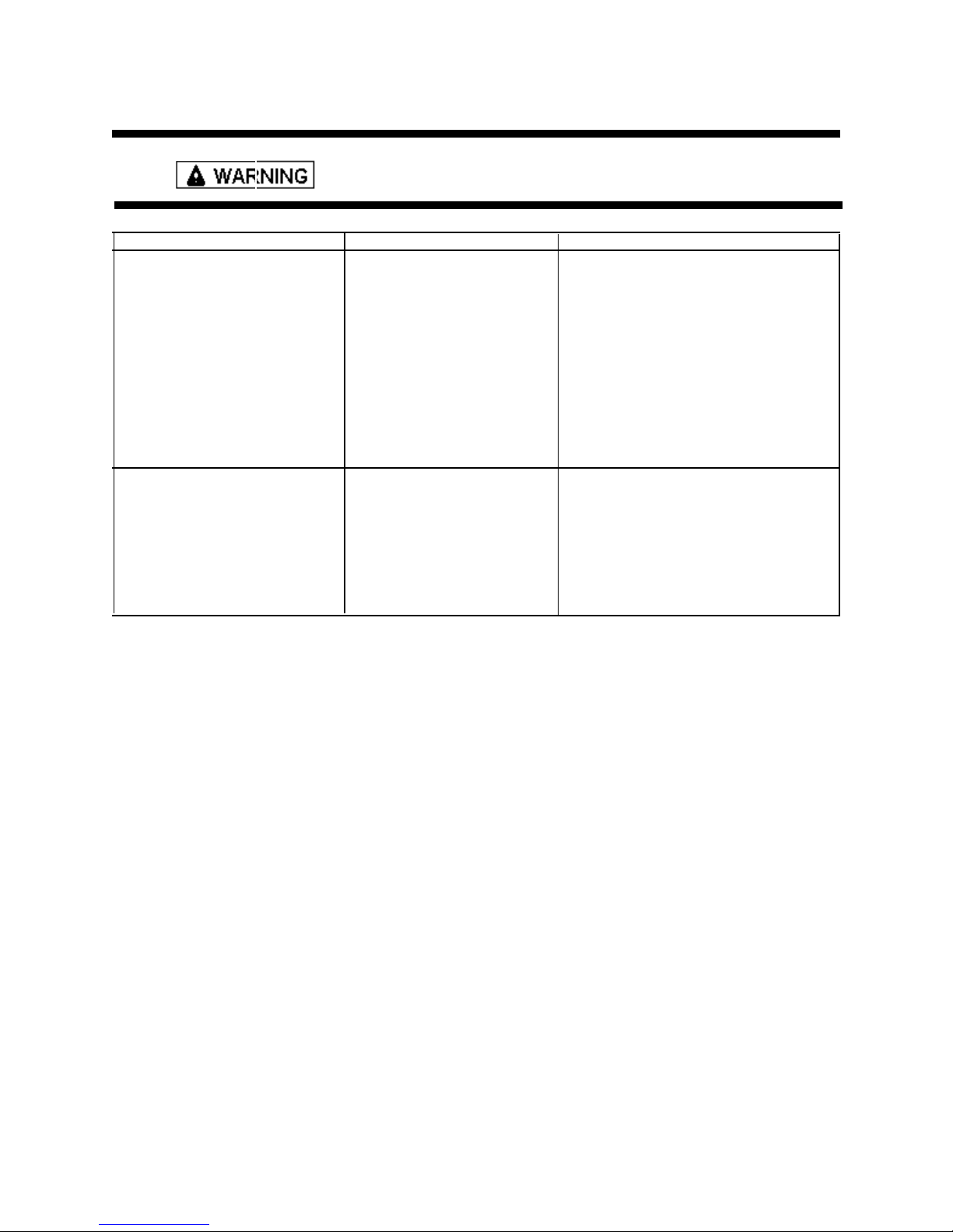
6. Oven light does not operate A. Failed light bulb. A. Replace bulb.
7. Oven light stays on. A. Burned out bulb. A. Check light switch contacts for
C. Failed light socket.
Problem Probable Cause Correction
B. Failed light switch B. Check light switch contacts for
continuity. Replace light switch
if necessary..
C. Failed light socket. C. Check for 120 VAC at the light
socket terminals. If voltage is
present, replace socket. If no
voltage is present, check for
broken wiring between hot
terminal block and light switch
and between light switch and
socket.
continuity.
B. Failed light switch contacts
19
Page 20
DISASSEMBLY PROCEDURES
To avoid the risk of electrical shock, personal injury or death, disconnect power
before servicing, unless testing requires it.
To avoid risk of personal injury or property damage this
unit requires a two man lift when lifting unit in or out of
cutout
Removing and Replacing Oven
1. Turn off power to the oven at the circuit breaker.
2. Open oven door and remove screws securing unit to
the wall.
3. Pull oven forward out of the cabinet opening.
4. Disconnect or unplug the power cord leading from
unit to fuse box or junction box depending on unit.
5. Disconnect gas supply from unit.
6. Replace the oven using the installation instructions.
After final gas connection is made, turn on manual gas
valve and test all connections in gas supply piping and
oven for gas leaks.
To avoid property damage or serious personal injury,
never use a lighted match to test for gas leaks.
Control Panel Assembly
1. Turn off power to unit.
2. Remove screws securing top piece to the unit.
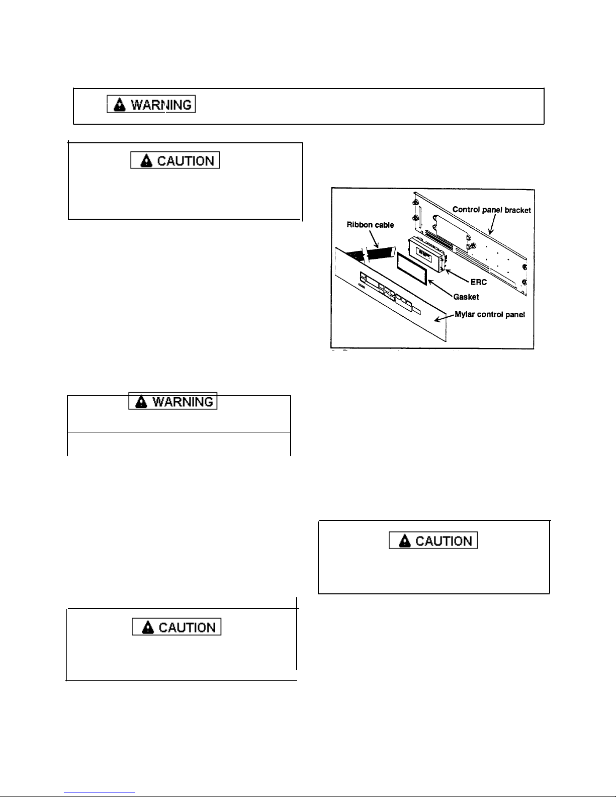
3. Mylar control panel is loose, but the ribbon cable
does not allow complete removal.
NOTE: Mylar control panel needs to be supported
while removing rest of assembly.
4. Remove screws securing bottom trim under Mylar
panel.
5. Remove screws securing control panel bracket.
6. Lean control panel bracket forward to disconnect
wire terminals and ribbon cable.
While unplugging electrical connections, pins may be
damaged, use extreme care when disconnecting.
7. Gently pull control panel up and forward to remove
complete assembly.
8. Reverse procedure to reassemble control panel.
ERC
1. Turn off power to unit.
2. Remove screws securing top trim piece to the unit.
3. Mylar control panel is loose, but the ribbon cable
does not allow complete removal.
NOTE: Mylar control panel needs to be supported
while removing rest of assembly.
4. Remove screws securing ECR to control panel
bracket.
5. Gently pull ECR forward to gain access to wire
terminals.
While unplugging electrical connections, pins may be
damaged, use extreme care when disconnecting.
6. Disconnect all electrical connections from ECR and
remove.
7. Reverse procedure to reassemble.
20
Page 21
DISASSEMBLY PROCEDURES
Mylar Control Panel
1. Turn off power to unit.
2. Remove screws securing top trim piece to the unit.
3. Mylar control panel is loose, but the ribbon cable
does not allow complete removal.
NOTE: Mylar control panel needs to be supported
while removing rest of assembly.
4. Remove screws securing ERC to control panel
bracket.
5. Gently pull ERC forward to gain access to ribbon
cable.
6. Disconnect ribbon cable from ERC and remove
Mylar control panel.
7. Reverse procedure to reassemble.
Transformer / Relay Board(s)
1. Turn power off to unit.
2. Remove control panel, see “Control Panel
Assembly” for removal.
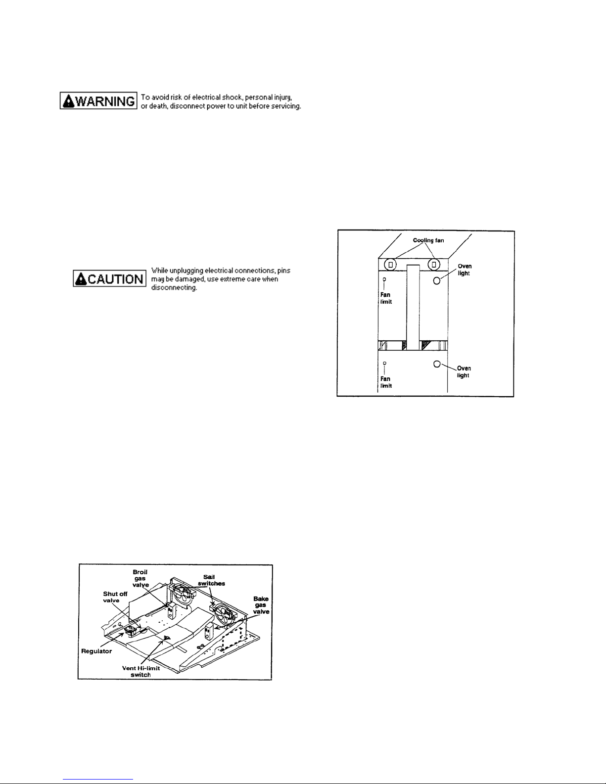
3. PC board is mounted to the chassis side walls
behind the control panel assembly.
4. Disconnect and label wire terminals.
5. Release plastic tabs securing circuit board.
6. Reverse procedure to reassemble.
Vent Hi-Limit Switch
1. Turn power and gas off to unit.
2. Remove control panel, see “Control Panel
Assembly” for removal.
3. Disconnect wire terminals from control limit switch.
4. Remove screws securing control limit switch.
5. Reverse procedure to reassemble.
Thermal Fan Limit Switch
1. Turn off and disconnect both electrical and gas
supplies to the unit.
2. Open oven door and remove screws securing unit to
the wall.
3. Remove unit from cutout opening.
4. Remove screws securing top or bottom back rear
outer wrapper from the unit, depending on which
limit switch need replaced.
5. Disconnect wiring terminal leads from limit switch.
6. Remove screws securing limit switch.
7. Reverse procedure to reassemble.
Oven Sensor
1. Turn off power to unit.
2. Open oven door or remove oven door, see “Door
Removal”.
3. Remove screws securing sensor to top right rear
corner of oven cavity.
4. Pull sensor forward, maneuver wires through
insulation to disconnect wire plug connector.
5. Reverse procedure to reassemble.
Upper Oven Door Latch / Door Plunger
Light Switch Assembly
1. Turn off power to unit.
2. See “Control Panel Assembly “ for removal.
3. Remove screws securing latch assembly to chassis.
4. Disconnect and label wire terminals.
5. Remove latch assembly from chassis.
6. Reverse procedure to reassemble door latch
assembly
21
Page 22
DISASSEMBLY PROCEDURES
Lower Oven Door Latch / Door Plunger
Light Switch Assembly
1. Turn off power to unit.
2. Remove top oven door, see “Oven Door” procedure.
3. Remove screws securing center trim between oven
doors.
4. Remove screws securing latch assembly to chassis.
5. Remove latch assembly from chassis.
6. Disconnect and label wire terminals.
7. Reverse procedure to reinstall door latch assembly.
Oven Light Bulb / Oven Light Socket
1. Turn off power to unit.
2. Open oven door to gain access to oven light.
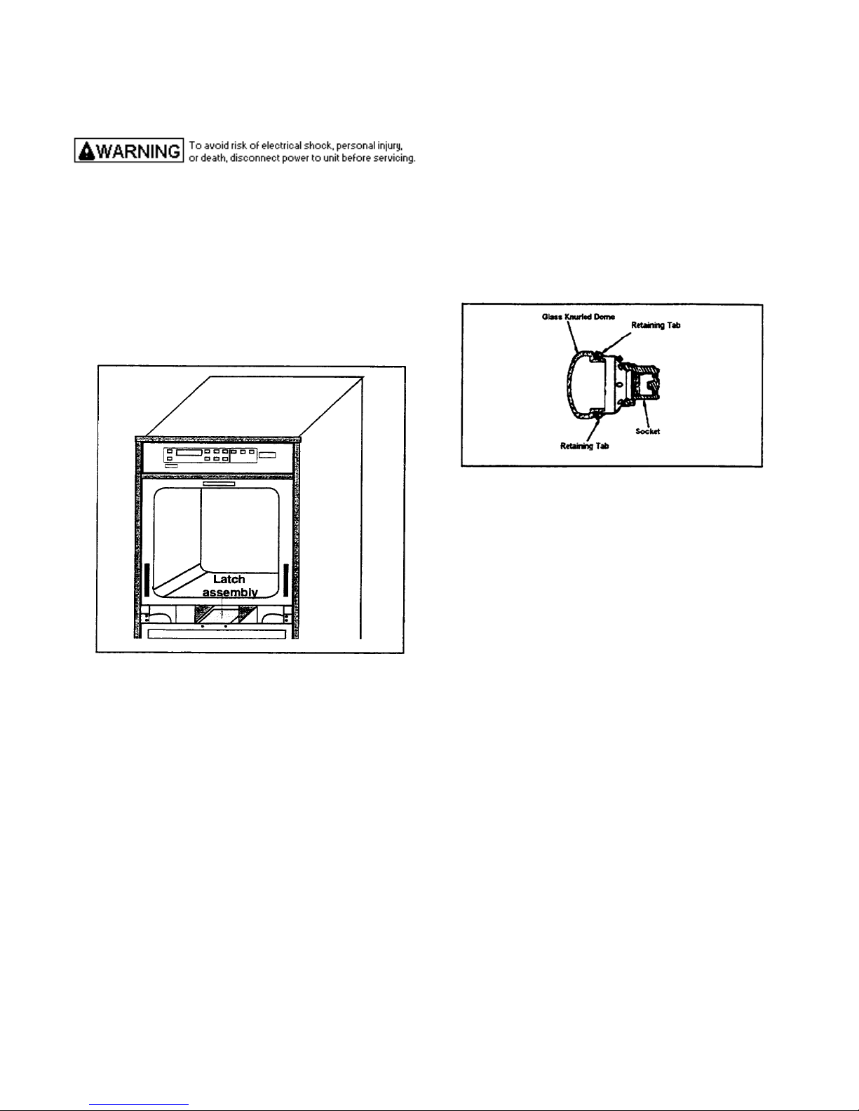
3. Unscrew (counterclockwise) glass knurled dome.
4. Using a glove, unscrew (counterclockwise) oven
light bulb.
NOTE: Proceed with the following steps for oven light
socket removal.
5. Remove screws securing unit to the wall.
6. Remove oven from cutout opening and disconnect
gas supply.
7. Disconnect or unplug the power cord leading from
unit to fuse box or junction box depending on unit.
8. Remove screws securing outer wrapper cover and
remove.
9. Carefully displace fiberglass insulation away from
rear of light socket.
10. Push inner assembly of light socket toward rear of
range, or twist out, depending on style of base.
11. Disconnect wires from light socket.
12. Reverse procedure to reinstall light socket.
Reposition insulation around lamp socket. Do not
over tighten.
NOTE: Reposition fiberglass insulation around oven
light socket to eliminate possibility of heat
related problems.
Oven Liner Removal
NOTE: Unit should be run through at least one clean
cycle to set insulation.
1. Turn off and disconnect both electric and gas
supplies to oven.
2. Remove oven door and oven racks.
3. Remove oven bottom and temperature sensor. Pull
capillary tube through side of oven.
4. Remove oven light cover and bulb.
5. Remove bake burner, ignitor, broil burner, and broil
ignitor.
6. Remove chip cover.
7. Remove cabinet back.
8. Remove screws securing oven liner at the rear.
Maneuver oven liner from frame by pulling
outward.
9. Reverse procedure to reassemble.
When reinstalling new liner, use flat sheet metal strips 4
X 28 inches to prevent insulation from “bunching up”
as new liner is installed.
NOTE: When removing oven liner be certain not to
dislodge the broil air duct on the right side of
cabinet. If air duct is dislodged, broiler burner
will not function as it will disrupt the flow of air
to the broiler, resulting in poor air-gas mixture.
22
Page 23
DISASSEMBLY PROCEDURES
Oven Door Removal
1. Open oven door and remove screws securing door to
hinge assembly.
2. Place oven door in first stop position, then grasp
both sides and lift up off the hinge.
NOTE: Door hinges are spring loaded and will snap
closed if bumped. Avoid pinching fingers by
closing hinges completely until ready to mount
door back on the unit.
3. Reverse procedure to reassemble.
Door Disassembly
1. Remove oven door, see “Door Removal”.
2. Remove screws on right, left, top, and bottom of
oven door.
3. Remove door liner from door assembly.
4. Remove screws securing inner glass support
securing glass and door handle.
5. Remove glass mounting bracket and glass window.
6. Remove screws securing heat door liner shield and
remove.
7. Reverse procedure to reassemble.
NOTE: When reassembling door, verify HB ll marking
on the glass is facing toward the heat (inside
of the oven).
Oven Door Hinge
1. Turn off power to unit.
2. Remove oven door, see “Door Removal”.
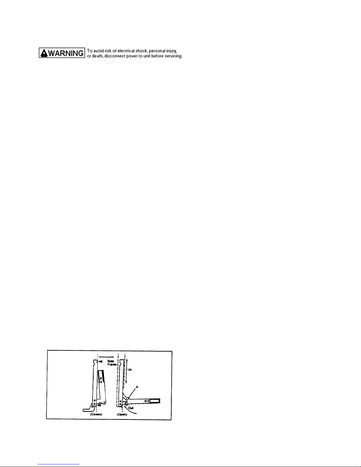
3. Carefully open the hinge fully, and insert a wooden
dowel or screwdriver bit into opening marked A on
the following diagram.
4. Remove the top and bottom screws securing hinge
assembly to the front frame.
5. Slide the hinge assembly up and move top of hinge
towards rear of the range. Withdraw hinge
assembly through the frame opening.
6. Reverse procedure to reinstall oven door hinge
assembly.
Blower Motor
1. Turn off and disconnect electrical and gas supplies
to the oven.
2. Open oven door and remove screws securing unit to
the wall.
3. Remove unit from cutout opening.
4. Remove screws securing top outer wrapper from the
unit.
5. Disconnect and label wire terminals connected to
blower motor.
6. Remove screws securing blower motor assembly to
bracket.
7. Reverse procedure to reassemble.
Vent Assembly
1. Turn off and disconnect electrical and gas supplies
to the oven.
2. Open oven door and remove screws securing unit to
the wall.
3. Remove unit from cutout opening.
4. Remove screws securing top and back outer
wrapper from the unit.
5. Remove screws securing vent assembly to unit.
6. Turn off and disconnect electrical and gas supplies
to the oven. Vent assembly and slowly maneuver
vent assembly away from unit.
7. Reverse procedure to reassemble.
Broil Ignitor
1. Shut off power and gas supply to oven.
2. Remove oven door and oven racks.
3. Unscrew broil ignitor wire cover mounting screw.
Remove cover.
4. Remove broil ignitor mounting screws. Pull ignitor
leads and connectors into oven cavity through hole
in broil chamber.
5. Disconnect ignitor wiring.
6. Reverse procedure to reassemble.
Broil Burner
1. Shut off power and gas supply to oven.
2. Remove oven door and oven racks.
3. Remove broil ignitor mounting screws. Remove
ignitor from broiler burner.
4. Remove broil burner mounting screws securing
burner to burner bracket.
5. Move burner up against burner bracket, push burner
towards rear of oven. Slide broiler burner out of
broil chamber.
6. Reverse procedure to reassemble.
23
Page 24

DISASSEMBLY PROCEDURES
Oven Burner Ignitor
1. Shut off power and gas supply to oven.
2. Remove oven door and oven racks.
3. Remove oven bottom by lifting from front and
sliding it out of oven.
4. Remove screws securing ignitor bracket to back
burner box. Remove screw securing ignitor to bake
burner.
5. Pull ignitor leads and connectors through opening.
Disconnect ignitor wiring.
6. Reverse procedures to reassemble.
Oven Burner
1. Shut off power and gas supply to oven.
2. Remove oven door and oven racks.
3. Remove oven bottom by lifting from front and
sliding it out of oven.
4. Remove screws securing ignitor bracket to back
burner box. Remove screw securing ignitor to bake
burner.
5. Disconnect and remove bake burner.
6. Reverse procedures to reassemble.
Pressure Regulator
1. Turn off and disconnect electrical and gas supplies
to the oven.
2. Remove control panel assembly, see “Control Panel
Assembly” procedures.
3. Unscrew and remove regulator from 90° elbow
fitting.
4. Reverse procedures to reassemble.
NOTE: Use a soap solution to check for leaks after
installing replacement regulator.
Shut - Off Valve
1. Turn off and disconnect electrical and gas supplies
to the oven.
2. Remove control panel assembly, see “Control Panel
Assembly” procedures.
3. Unscrew pressure regulator from 90° fitting.
4. Unscrew shut-off valve and fitting assembly from
gas manifold.
5. Unscrew 90° fitting from shut-off valve.
6. Reverse procedures to reassemble.
NOTE: Use soap solution to check for leaks after
installing replacement valve.
Sail Switch
1. Shut off electrical and gas supplies to the oven.
2. Remove control panel assembly, see “Control Panel
Assembly” procedures.
3. Remove screws securing sail switch mounting
bracket to control compartment back. Disconnect
switch wiring.
4. Remove sail switch and bracket assembly.
5. Reverse procedures to reassemble.
24
Page 25

DISASSEMBLY PROCEDURES
Door Assembly
25
Page 26
INSTALLATION INSTRUCTIONS
Packing Material
Remove protective packing material from oven. Tape
residue can be cleaned with a soft cloth and alcohol.
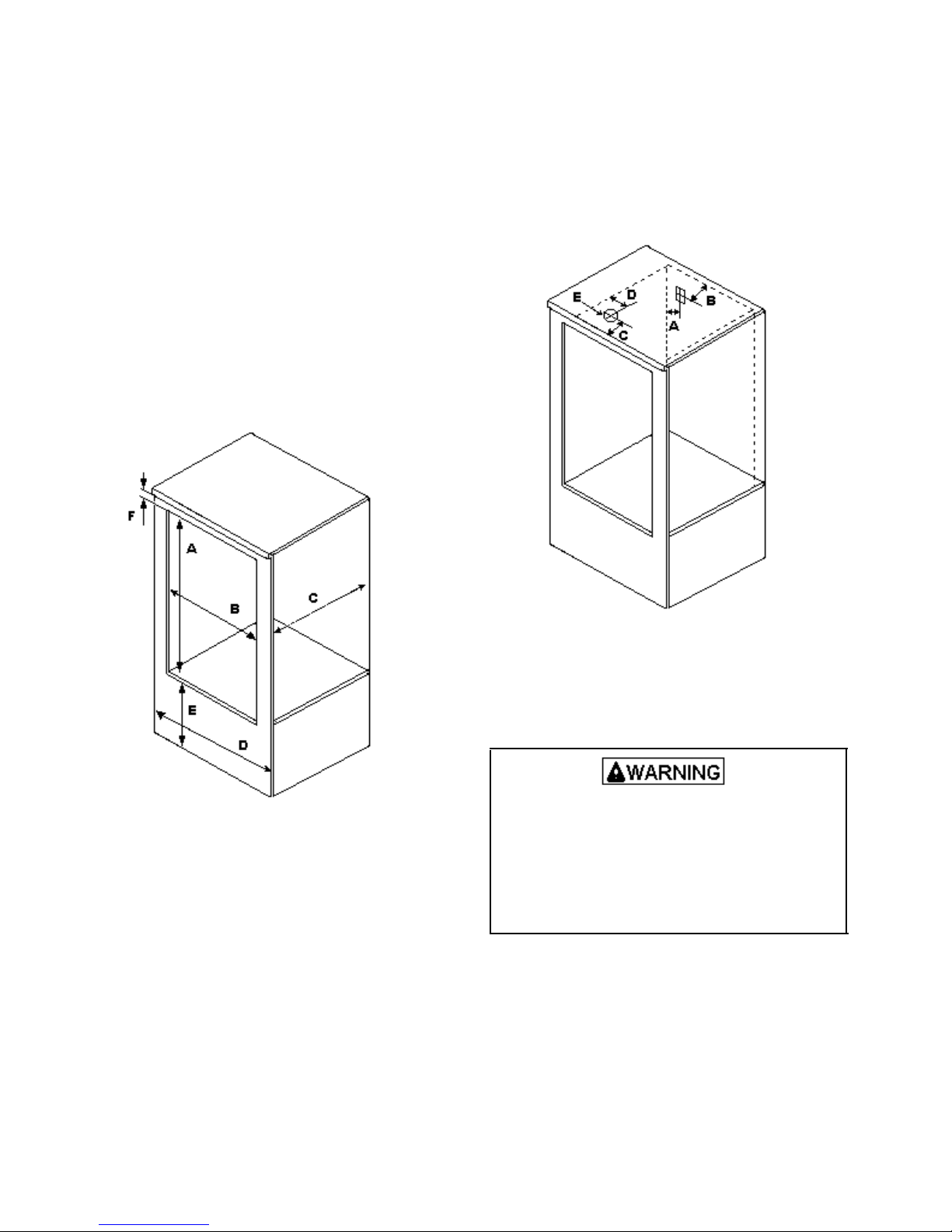
Oven Location
Choose a location based on following factors.
• Make sure there is adequate space for proper
installation.
• Carefully read all instructions before beginning
installation.
A --- 54 inches
B --- 25 inches
C ---23 3/4 inches
D ---27 inches
E ---12 ½ inches
F --- 3 inches
Gas and Electric Supply Location
Gas supply must be located in the area shown. Gas
connection must not interfere with the electrical
connection.
Electrical Gas
A --- 8 inches C --- 5 ½ inches
B --- 5 inches D --- 5 inches
E --- 4 inch round hole
Electrical Connection Requirements
To avoid the risk of serious electrical shock or property
damage, do not cut or remove the third (ground) prong
from the power plug. A 3-wire grounded conductor
system must be used. Relying on the flexible
connector, hard piping or any other part of the part of
the gas supply line as a ground may cause fire,
electrical shock and/or erratic control operation.
Oven must be electrically grounded in accordance with
local codes or in the absence of local codes, with the
National Electrical Code, ANSI/NFPA #70-latest
edition.
26
Page 27
INSTALLATION INSTRUCTION
In Canada, electrical connections are to be made in
accordance with CSA C22.1 Canada Electrical Code.
All electrical connections are to be made in accordance
with CSA standards Z240.6.1 electrical requirements
for mobile homes.
Use a 120 volt, 60 hertz, 3-prong receptacle protected
by a 15 amp circuit breaker or time delay fuse. A
qualified electrician should confirm the outlet is
properly grounded and polarized.
If a 2-prong outlet is encountered, home owner must
replace outlet before using oven. Do not cut off cord,
use plug adapter or extension cord, or remove
grounding plug.
Gas Connection Requirements
Before connecting this appliance to the gas supply
piping system, confirm installation meets the
requirements of local codes, or in the absence of local
codes, with the National Fuel Gas Code, ANSI Z223.1Latest Edition.
When installed in mobile housing, installation is to be
in accordance with CSA standard A241.1 gas equipped
mobile housing.
The installation of appliances designed for
manufactured (mobile) home installation must conform
with Manufactured Home Constriction and Safety
Standard, Title 24 CFR, Pare 3280, or when such
standard is not applicable, the Standard for
Manufactured Home Installation, ANS1225.1/NPA 501
A-Latest Edition, or with local codes or the standard
CAN/CSA-Z240MH, “Mobile Homes”, and with local
codes where applicable.
The installation of appliances is to be in accordance
with CAN1-B149.1 or B149.2 installation code for gas
burning appliances and equipment and/or local codes.
Part1 and/or local codes.
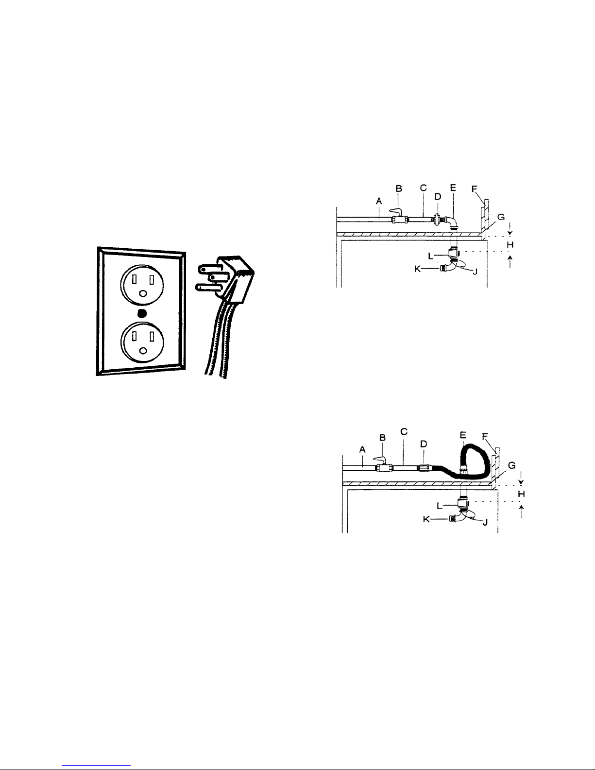
Assemble gas supply line to oven. All gas supply
piping tubing, fittings, and shutoff valves are not
supplied with this oven. See examples.
NOTE: Refer to National Fuel Gas Code to determine
gas pipe sizing requirements, if oven
performance is in question.
A --- ½-inch rigid pipe supply line.
B --- Manual shutoff valve
C --- Nipple
D --- Union
E --- Elbow
F --- Upper cabinet door or removable panel
G --- Upper cabinet shelf.
H --- 2 1/4 inches
J --- L.P. orifice spuds.
K --- Inlet to oven.
L --- Pressure regulator.
A --- ½-inch rigid pipe supply line.
B --- Manual shutoff valve.
C --- Nipple
D --- Adapter.
E --- Flexible gas connector.
F.--- Upper cabinet door or removable panel.
G--- Upper cabinet shelf
H --- 2 1/4 inches.
J --- L.P. orifice spuds
K --- Inlet to oven
L --- Pressure regulator.
27
Page 28
INSTALLATION INSTRUCTIONS
G as Supply Pressure
To avoid property damage, maximum gas supply
pressure must not exceed 14" WCP.
• Appliance and individual shutoff valve must be
disconnected from the gas supply piping system
during any pressure testing of that system at test
pressures in excess of ½ psig (3.5 kPa) (14" WCP).
• Appliance must be isolated from gas supply piping
system by closing manual shutoff valve during any
pressure testing of the gas supply piping system at
test pressures equal to or less than ½ psig (3.5 kPa)
(14"WCP).
• Gas supply pressure for checking regulator setting
must be at least 1" WCP above manifold pressure
shown on rating label.
Seal Openings
Openings in wall behind the oven or on the floor under
oven must be sealed before sliding oven into position.
Place Oven in Wall
This procedure should be performed by 2 people.
1. Lean oven to each side and remove shipping base.
2. Move wall oven close to wall opening and plug in
oven cord.
3. Place in wall opening.
4. Secure wall oven to cabinet with 4 screws.
Converting Pressure Regulator for Use with
Natural Gas or Propane Gas
This oven arrives from factory adjusted for use with
natural gas. If using LP/propane gas is desired, oven
ust be converted. See “Type 1" or Type 2" regulator. m
To avoid electrical shock that can cause personal
Injury or death, disconnect main electrical supply
To oven before servicing.
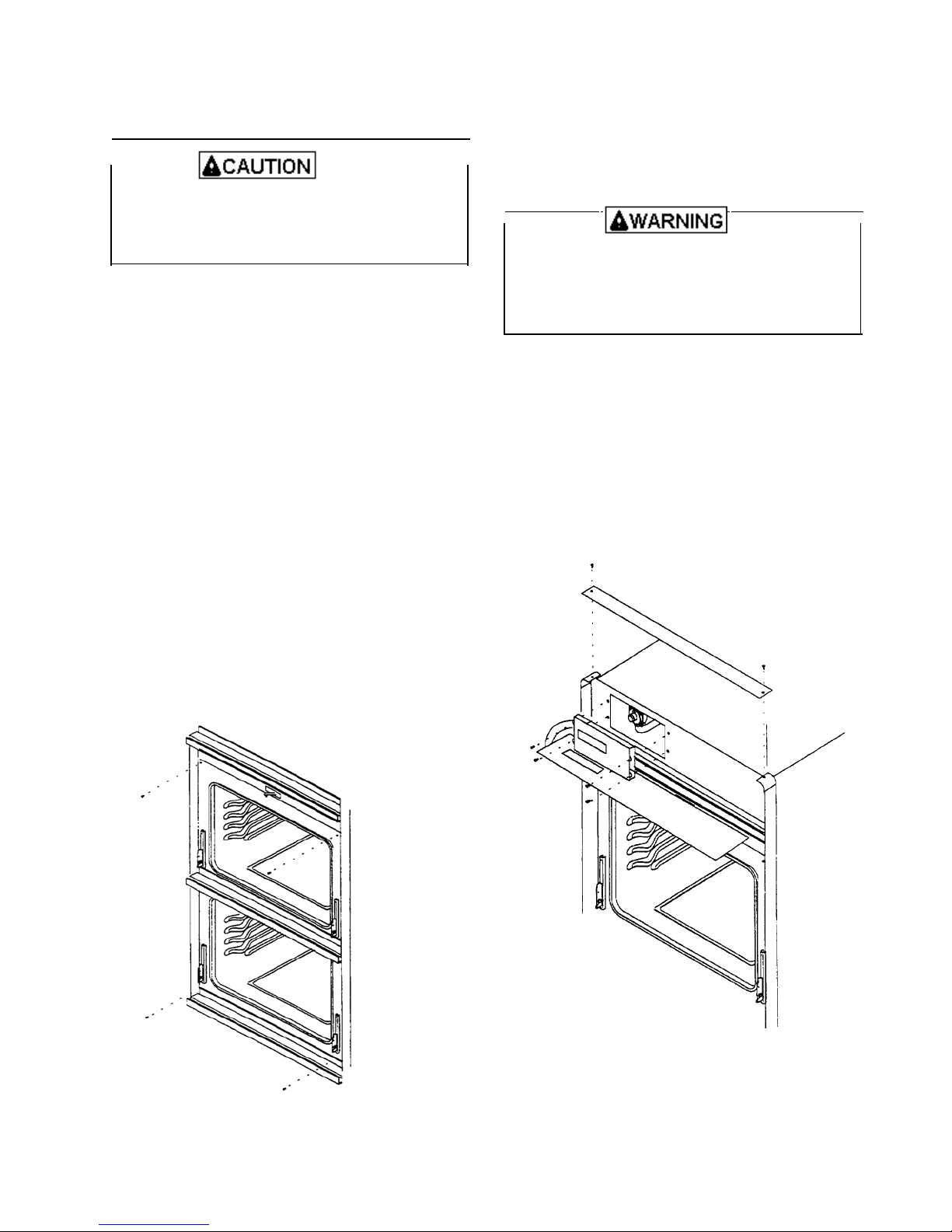
Remove Control Panel
To convert pressure regulator remove oven control
panel.
1. Remove 2 screws and lift off top trim.
2. Tilt control panel out to expose electronic range
control.
3. Remove 4 screws and pull out range control to
expose pressure regulator.
• Broiler burner orifice spuds are wired to
manifold behind pressure regulator.
4. After converting broiler burners and wiring orifice
spuds to manifold, see “Testing for Gas Leaks”
section, reverse procedure to reinstall control panel.
28
Page 29
INSTALLATION INSTRUCTIONS
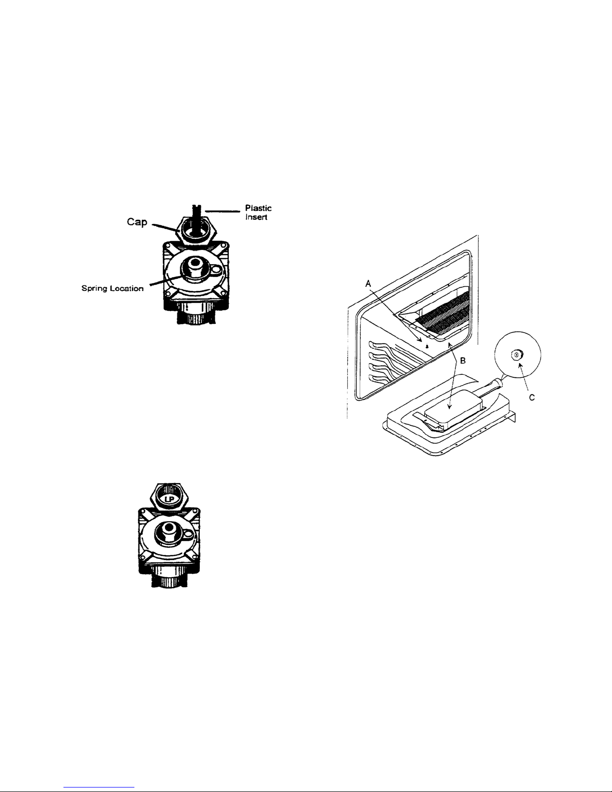
Converting Type 1 Pressure Regulator for Use with
LP/ Propane
1. Remove pressure regulator cap with a wrench.
2. Remove plastic insert from pressure regulator cap.
• Plastic insert fits tightly in cap.
3. Reverse plastic insert and carefully push plastic
insert firmly into hole in pressure regulator cap.
• Cap must show “LPG10" or “LP10".
4. Place pressure regulator cap on pressure regulator
and tighten.
• Insert should not disturb spring in body of
regulator.
Converting Type 2 Pressure Regulator for Use with
LP/Propane
1. Remove pressure regulator cap with a wrench.
2. Reverse pressure regulator cap.
• Cap must show “LP”.
3. Place pressure regulator cap on pressure regulator
and tighten.
Converting Broiler Burner for Use with LP/Propane
1. Locate orifice spud attached adjacent to pressure
regulator and remove for later use.
2. Open oven door and locate broiler burner on oven
ceiling.
• Remove oven door to make conversion easier.
See “Removing Oven Door” section.
3. Remove screw securing front of burner to oven
ceiling and remove broiler.
• Be careful not to damage ignitor while removing
broiler.
A--- Remove Screw B --- Broiler C --- Orifice
4. Unscrew natural gas burner spud stamped “52" with
5/16-inch socket wrench and replace with
LP/propane burner spud stamped “58".
• Attach unused burner spud near regulator for
future use.
5. Reinstall broiler.
29
Page 30
INSTALLATION INSTRUCTIONS
Converting Oven Burners for Use with LP/Propane
Lower burner orifices and air shutters are located
behind front trim. Remove oven trim to convert oven
burners.
1. Remove oven doors.
• See “Removing Oven Doors” section.
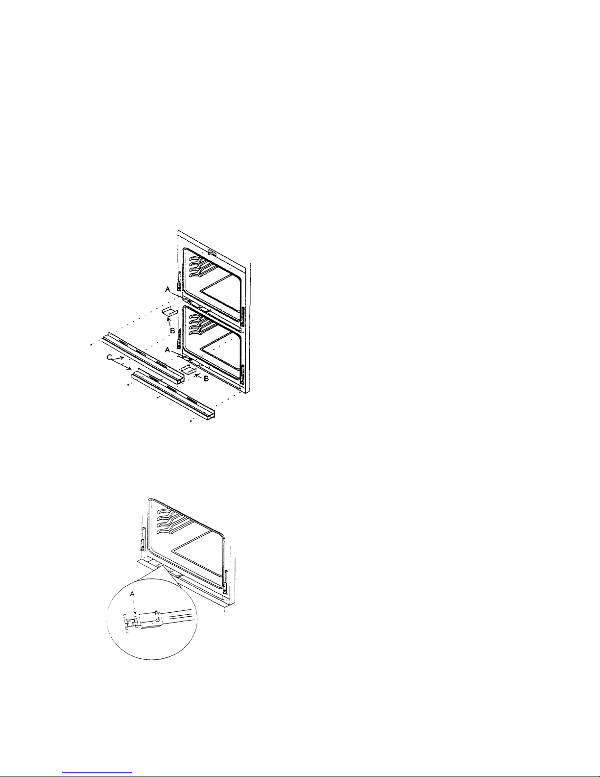
2. Remove screws (3) from each trim piece.
3. Pull trim away from oven.
• Each orifice box has an air channel. Air channel
must be in place before reinstalling trim.
• Reverse procedure to reinstall trim.
A --- Air Channel B --- Orifice Box C --- Trim
4. Turn (tighten) orifice hood clockwise until snug.
• Do not over tighten orifice hoods. Orifice hoods
can strip.
5. Replace trim after burner is tested and air shutter is
properly adjusted.
• See “Test and Adjust Oven Burner “ section.
Converting Type 1 Pressure Regulator for Use with
Natural Gas
1. Remove pressure regulator cap with a wrench.
2. Remove plastic insert from pressure regulator cap.
• Plastic insert fits tightly in cap.
3. Reverse plastic insert and carefully push plastic
insert firmly into hole in pressure regulator cap.
• Insert must show “NAT” or be blank.
4. Place pressure regulator cap on pressure regulator
and tighten.
• Insert should not disturb spring in body of
regulator.
Converting Type 2 Regulator for Use with Natural
Gas
1. Remove pressure regulator cap with a wrench.
2. Reverse pressure regulator cap.
• Insert shows “NAT” or is blank.
3. Place pressure regulator cap on pressure regulator
and tighten.
Converting Oven Burner for Use with Natural Gas
Lower burner orifices and air shutters are located
behind front trim. Remove oven trim to convert oven
burners.
1. Remove oven doors.
• See “Removing Oven Door” section.
2. Remove screws (3) from each trim piece.
3. Pull trim away from oven.
• Each orifice box has an air channel. Air channel
must be in place before reinstalling trim.
• Reverse procedure to reinstall trim.
4. Turn (loosen) orifice hood counterclockwise 2 full
turns.
5. Replace cover plate and storage drawer.
A – Orifice Hood
30
Page 31
INSTALLATION INSTRUCTIONS
Converting Broiler Burner for Use with Natural Gas
1. Locate orifice spud attached adjacent to pressure
regulator and remove for later use.
• Orifice spud used for natural gas is silver and is
stamped “52".
2. Open oven door and locate broiler burner on oven
ceiling.
• Remove oven door to make conversion easier.
See “Removing Oven Door” section.
3. Remove screw securing front of burner to oven
ceiling and remove broiler.
• Be careful not to damage ignitor as you remove
broiler.
4. Unscrew LP/propane burner spud stamped “58"
with 5/16 inch socket wrench and replace with
natural gas spud stamped “52". Replace LP spuds
on inlet piping.
5. Reinstall broiler and, if necessary, oven door.
Gas Connection
Connect gas supply to regulator using hard pipe or
flexible connector (check local codes). Pressure
regulator supplied with this appliance has a ½ inch NPT
female connector.
• A manual shutoff , not supplied with oven, must be
installed in an accessible location outside of oven.
• Use joint compound that is resistant to action of
propane gas on all male pipe threads.
• Do not over tighten gas fitting when attaching to
pressure regulator. Over tightening may crack
regulator.
• Support pressure regulator with wrench when
installing gas fitting.
To avoid property damage or personal injury, only
use a new flexible connector that is AGA/CGA
design certified.
• Do not use an old connector.
• Do not reuse a connector after moving
appliance.
Testing for Gas Leaks
After final gas connections are made, turn on manual
gas valve and test all connections in gas supply piping
and oven for gas leaks.
To avoid property damage or serious personal injury,
never use a lighted match to test for gas leaks.
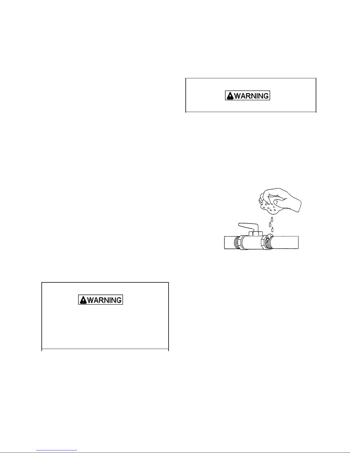
1. Place soap suds on connection.
• Bubbles appear if leak is present.
2. If bubbles appear, shut off gas supply valve.
3. Tighten joint if leak is at factory fitting.
• If leak is not at factory fitting, unscrew, apply
more joint compound, and tighten to correct
leak.
4. Retest connection for leak after tightening.
• Retest any connections that were disturbed.
Test Oven Burner Flame
Properly adjusted oven burner flames are blue with a
distinct deep blue inner cone approximately ½ inch
long. When using natural gas, flame should not have
any yellow flame when burning. Some yellow flame
when burning LP/propane gas is normal.
Flame should not be visible in the oven cavity when
burning and should not extend into the oven cavity
beyond the removable oven bottom.
• If burner flame is blowing or noisy, reduce airflow
to burner.
• If burner flame is yellow and does not hold its
shape, increase airflow to burner.
31
Page 32
INSTALLATION INSTRUCTIONS
Adjust Oven Burner Flame
To avoid electric shock that can cause personal
injury or death, disconnect main electrical supply
to oven before servicing.
Lower burner orifices and air shutters are located
behind front trim. Remove oven trim to adjust oven
burners.
1. Remove oven doors.
• See “Removing Oven Door” section.
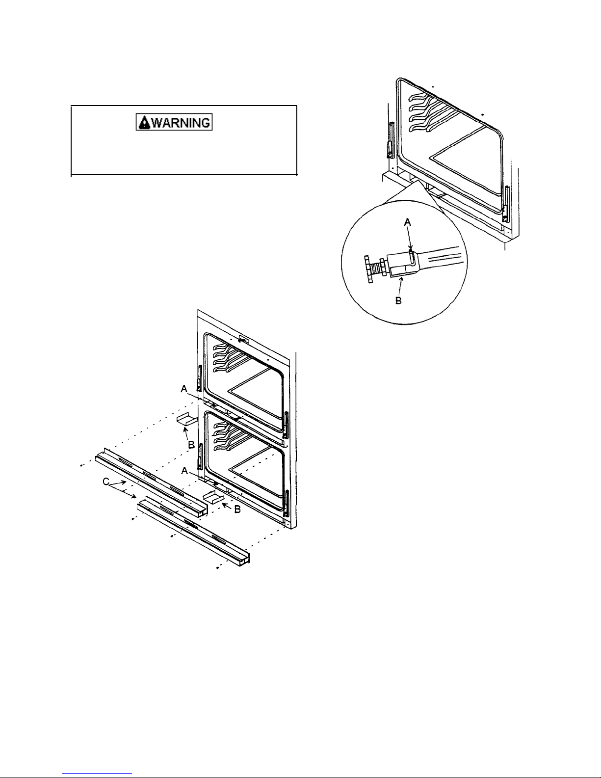
2. Remove screws (3) from each trim piece.
3. Pull trim away from oven.
• Each orifice box has an air channel. Air channel
must be in place before reinstalling trim.
• Reverse procedure to reinstall trim.
A --- Air Channel B --- Orifice Box C --- Trim
4. Loosen air shutter screw and open or close air
shutter.
A --- Air Shutter screw B --- Air Shutter
5. Replace trim after burner is tested and air shutter is
properly adjusted.
Test Broiler Flame
Broiler flame should appear hazy or fuzzy. Haze
should be no more than 3/8 inch thick. The radiant
screen should begin to glow red within 1--2 minutes.
Removal and Replacement of Oven
1. Disconnect power to oven at circuit breaker or fuse
panel.
2. Turn off manual shutoff valve, and disconnect gas
supply.
3. Remove oven, unplug power cord, and place oven
aside.
4. To reinstall oven, follow instructions in Installation
section of this manual.
• Do not reuse a flexible connector after moving
appliance.
32
Page 33

PROGRAMMING INSTRUCTIONS
Controls clock, timer, and interior oven light for both ovens. STOP TIME pad is used to program delayed bake and
delayed clean features for both upper and lower ovens.
Oven Control Description
Pad Description
OVEN LIGHTS Turn light on and off in both upper and lower ovens.
TIMER ON/OFF Use to time any kitchen function or cancel timer. Does not
control bake, broil, or clean functions.
CLOCK Use to set time of day.
STOP TIME Use to set delayed bake and delayed self-clean.
OFF / CANCEL Cancels any baking or cleaning function except timer.
COOK TIME Use to set timed baking.
CLEAN Use to set self-clean cycle.
BROIL Use to select broil.
BAKE Use to select bake.
+ or - Use to set temperature or time.
Controls upper oven settings. Any time or
temperature settings entered only effect
upper oven.
Controls lower oven settings. Any time or
temperature settings entered only effect lower
oven.
33
Page 34
PROGRAMMING INSTRUCTIONS
Display
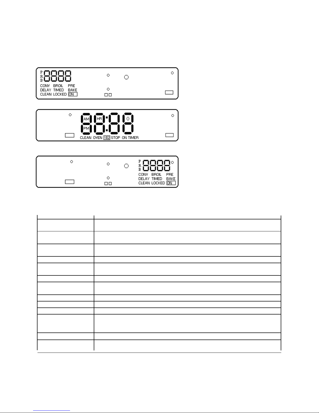
Some items in display can be seen but will not glow.
Displays temperature and baking
method or function for upper oven.
Displays time-of-day, timer and
Timed of delayed settings.
Displays temperature and cooling
method or function for lower oven.
DESCRIPTION of DISPLAY
TIME AM, PM or HR TIME AM or PM Flashes in display while time-of -day is entered. TIME HR flashes
TIMER Flashes in display while timer is set. TIMER stops flashing and displays while time
counts down.
PRE-BAKE, BAKE BAKE flashes while bake oven temperature is entered. While oven preheats PRE BAKE displays. After oven has reached temperature, BAKE displays.
ON Displays when oven is heating.
OVEN 1 or 2 Flashes while time is entered for timed or delayed baking. 1 displays when upper
TIMED BAKE Flashes, then displays when a time baking cycle is set.
DELAYED TIME Displays when delayed bake or self-clean cycle is set.
BAKE or CLEAN
STOP Displays when setting stop time for a delayed baking or self-clean cycle.
BROIL Flashes, then displays when a broil is set.
CLEAN Displays when self-clean cycle is entered and set.
LOCK LOCK flashes while oven door is locked and remains in display while door is locked.
HLD Displays when oven is holding oven temperature at 170°F for 1 hour.
SLO Displays when oven is set to slow-bake temperature. Oven cooks like crockpot for
when time is entered for timed or delayed baking or delayed self-cleaning.
oven is set. 2 displays when lower oven is set.
After cycle is complete and oven has cooled to a safe temperature, LOCK no longer
displays and door can be opened.
up to 12 hours. Approximately 225°F.
34
Page 35
PROGRAMMING INSTRUCTIONS
Oven Signals
Preheat signal After setting oven to bake and selecting a temperature, oven preheats. When
Timer and end-of-cycle When a timed baking cycle is complete or time elapses on timer, three long signals
Signal sound, then once approximately every 6-8 seconds. End of cycle signal continues to
Other Features
12-hour automatic cancel This safety feature prevents oven from continuing to operate if it has been left on
Child lockout This safety feature is used to prevent children from accidentally programming oven
Service codes and tones Electronic range control is equipped with a self diagnostic system. Self diagnostic
Sounds
Oven Fan Oven cooling fan can turn on while oven is heating to cool range control
oven reaches set temperature, 1-second signal sounds.
sound until OFF/ CANCEL pad is pushed .
If minute timer end of cycle signal is sounding, push TIMER ON/OFF pad.
No signal will sound at the end of a clean cycle.
for over 12 hours. If a cooking function continues longer than 12 hours without any
options on oven control being touched, this feature turns oven off. Any time an
option is touched, 12-hour automatic cancel is reset.
by disabling electronic oven control. On the upper oven control press and hold
BAKE and BAKE TIME for 5 seconds. “OFF” displays where the temperature
normally appears. To reactivate control, press and hold BAKE and BAKE TIME
pads for 5 seconds on the upper oven control. Child lockout must be reset after a
power failure.
system alerts you if there is an error or problem in the control. If electronic range
control sounds a series of short, rapid beeps for over 16 seconds and display shows
a F-code, record the F-code shown. Some F-codes can be cleared by touching
OFF/ CANCEL or disconnecting power to the range. If the code continues to
reoccur call an authorized servicer. Disconnect electrical supply to range and
contact an authorized servicer.
F1--Control malfunction
F2--High oven temperature
F3--Temperature sensor malfunction
F4--Temperature sensor malfunction
F7--Touch pad malfunction
F9--Door lock malfunction (door unlocked)
FF--Door lock malfunction (door locked)
35
Page 36

PROGRAMMING INSTRUCTIONS
Quick Reference Instructions
Read “Important Safety Instructions” before using
“Quick Reference Instructions”. If there are
unanswered questions, see detailed sections of this
manual.
Flashing Display
When power is connected to oven display flashes.
Press OFF/ CANCEL to clear display.
Setting Electronic Clock
1. Press CLOCK pad.
2. Press + or - pad until correct time-of-day displays.
• Clock saves time-of-day approximately 5-10
seconds after time is entered.
Setting Electronic Timer
1. Press TIMER pad.
2. Press + or - pad until correct time displays.
3. Press TIMER pad again to cancel
Resetting and Canceling Timer
To reset the time when remaining time is displayed,
press + or - pad until new time displays. To cancel
timer, press and hold TIMER pad for approximately 5
seconds.
Baking
1. Press BAKE pad.
2. Press + or - pad until desired temperature is
displayed.
3. Press OFF/ CANCEL pad when finished.
Time Baking
1. Place food in oven.
2. Press BAKE TIME pad.
3. Press + or - pad until desired baking time is
displayed.
4. Press BAKE pad.
5. Press + or - pad until desired temperature displays.
6. Press OFF/ CANCEL pad when finished.
Delayed Baking
1. Place food in oven.
2. Press BAKE pad.
3. Press + or - pad until desired temperature is
displayed.
4. Press STOP TIME pad.
5. Press + or - pad until desired stop time displays.
6. Press BAKE TIME pad.
7. Press + or - pad until desired baking time displays.
To Cancel Remaining Baking Time
1. Press OFF/ CANCEL pad.
Instant Broil
1. Center food on broiling grid and pan, and place on
rack in oven.
2. Push BROIL pad.
3. Press + pad to set HI, -pad to set lower broil
temperature.
4. Press OFF/ CANCEL pad when finished.
Self-cleaning
1. Prepare oven for self-cleaning.
2. Press CLEAN pad.
3. Press + or - pad to adjust desired amount of
cleaning time.
4. Press OFF/ CANCEL pad when finished.
Delayed Self-clean Cycle
1. Prepare oven for self-cleaning.
2. Press CLEAN pad.
3. Press + or - pad to adjust desired amount of
cleaning time.
4. Press STOP TIME pad.
5. Press + or - pad until desired stopping time
appears in display.
6. Press OFF/ CANCEL pad when finished.
Interrupt Self-clean Cycle
1. Press OFF/ CANCEL pad.
2. After oven has cooled to a safe temperature, door
can be opened.
Hold
1. Press BAKE pad.
2. Press - pad until 170° , then HLD is displayed.
3. Press OFF/ CANCEL pad when finished.
Slow Bake
1. Press BAKE pad.
2. Press -pad until 170°, then HLD, and then SLO is
displayed.
3. Pres OFF/ CANCEL pad when finished.
Timed Slow Bake
1. Place food in oven.
2. Press BAKE TIME pad.
3. Press + or - pad until desired baking time is
displayed.
4. Press BAKE pad.]
5. Press + or - pad until 170°, then HLD, and then
SLO is displayed.
36
Page 37
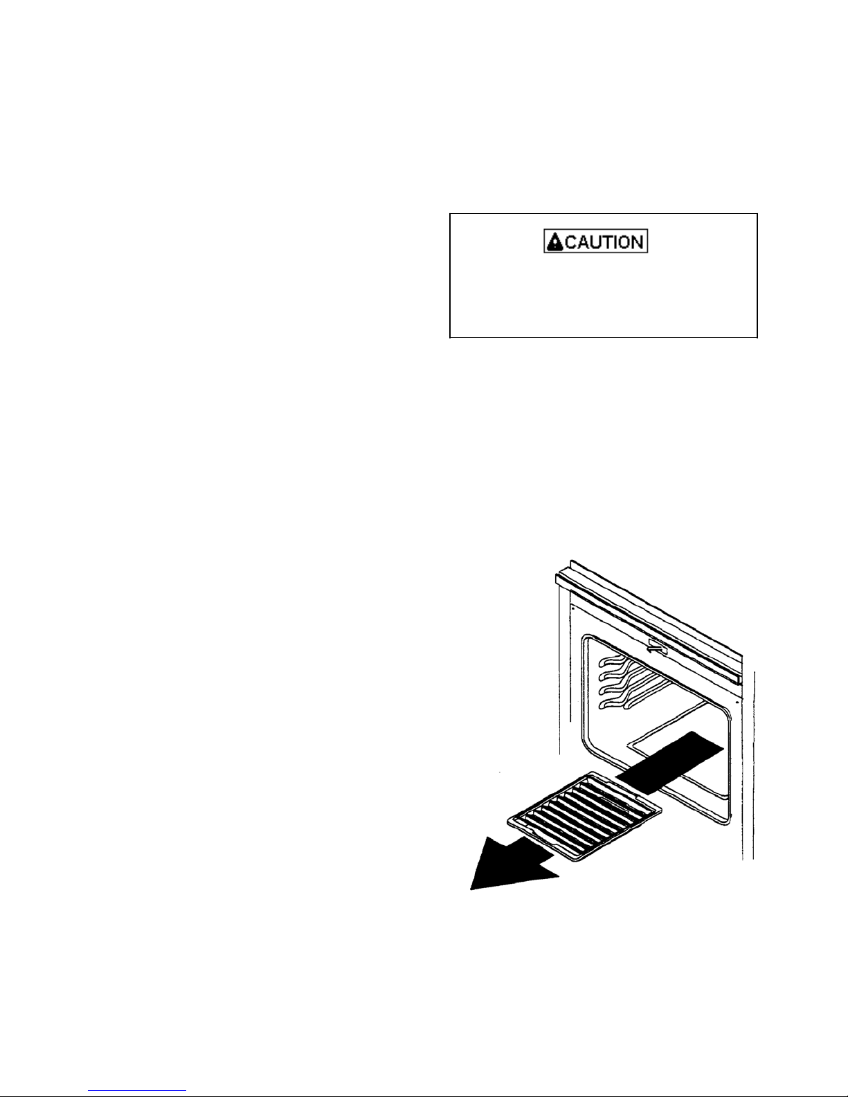
PROGRAMMING INSTRUCTIONS
6. Press OFF/CANCEL pad when finished.
Delayed Slow Bake
1. Place food in oven.
2. Press STOP TIME pad.
3. Press + or - pad until desired baking time displays.
4. Press BAKE TIME pad.
5. Press + or - pad until desired baking time displays.
6. Press BAKE pad.
7. Press - pad until 170°, HLD, and then SLO is
displayed.
To Cancel Remaining Baking Time
Press BAKE CANCEL pad.
Flashing Display
When power is connected to oven display flashes.
Press OFF/CANCEL to clear display.
Setting Electronic Clock
When power is connected or restored, display flashes
until pad is pressed.
1. Press CLOCK pad.
2. Press + or - pad until correct time-of-day displays.
• Time increases in larger increments the longer
+ or - pad is held.
• Clock saves time-of-day approximately 5-10
seconds after time is entered.
Setting Electronic Timer
The timer is a timer only. Electronic timer does not
control bake, broil, or self-clean function. Timer can be
set up to 11 hours and 50 minutes. Up to 1 hour, timer
displays minutes and seconds. After 1 hour, timer
displays hours and minutes.
1. Press TIMER ON/OFF pad.
2. Press +or - pad until correct time displays.
• Timer increased in larger increments the longer
+ or - pad is held.
• Timer begins counting down automatically after
time is entered.
3. Press TIMER ON/OFF pad to cancel timer signal.
• After time elapses, timer beeps approximately
once a second until TIMER ON/OFF pad is
pressed.
Resetting and Canceling Timer
To reset the time when remaining time is displayed,
press TIMER ON/OFF pad, then + or - pad until new
time displays.
To cancel timer, press and hold TIMER ON/OFF pad
for approximately 5 seconds.
Also, to cancel timer, press TIMER ON/OFF pad, then
press + or - pad until timer displays “00".
Prepare to Bake, Broil, Timed Bake, and Delayed
Bake
To reduce risk of food poisoning due to bacterial
growth and production of toxins, never hold meat,
milk, fish or eggs for more than 2 hours before
cooking.
Remove Items Stored in Oven
Remove any pans and other cooking utensils stored in
oven. Items left in oven can cause damage to the oven
or item in oven.
Never store the broiler pan or place utensils directly on
the oven bottom. If the broiler pan or utensils are left on
the oven bottom while heating, the oven bottom can
chip or be damaged.
37
Page 38
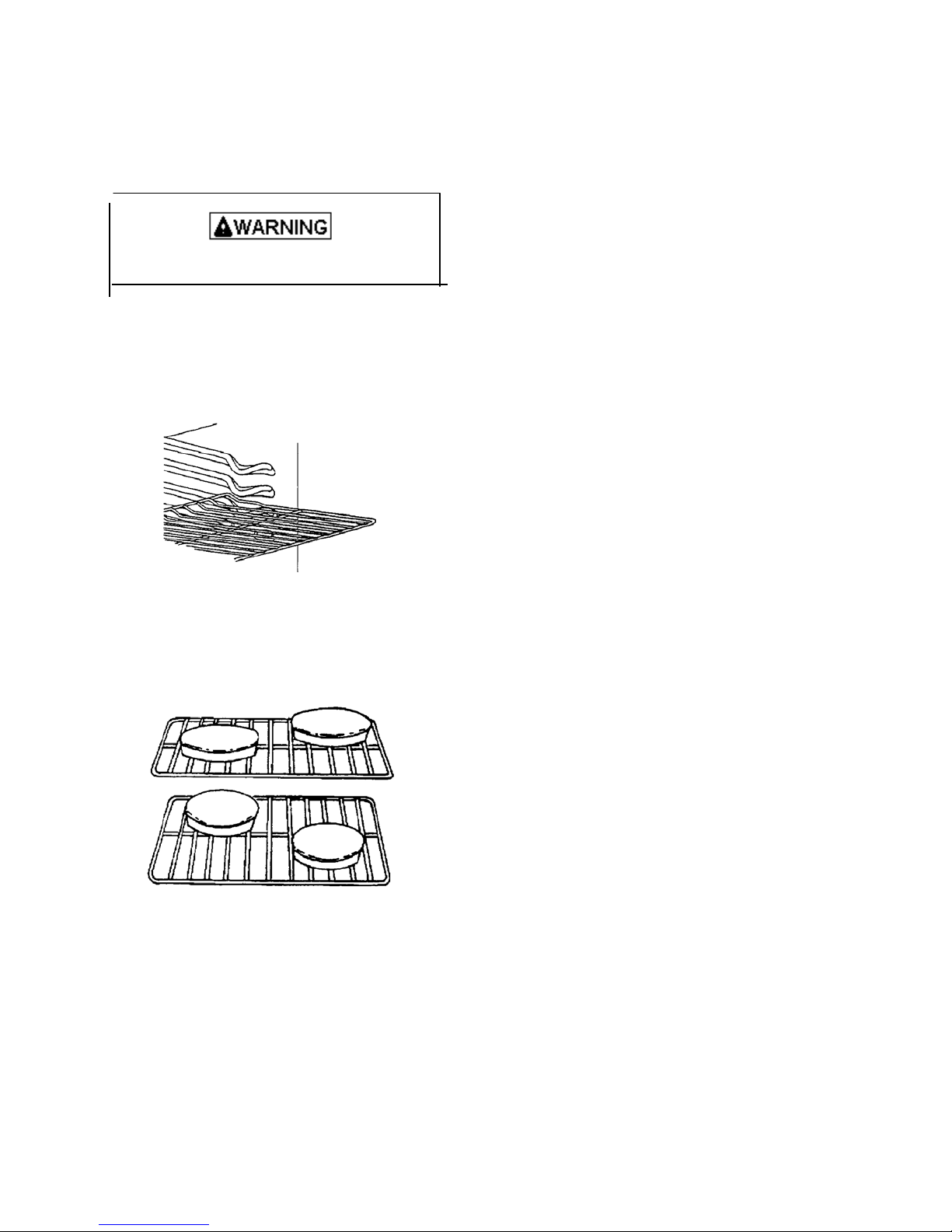
PROGRAMMING INSTRUCTIONS
Oven Rack Placement
Position oven rack before turning oven on.
To avoid damaging oven liner or creating fire, do
not line oven bottom or oven racks with foil.
1. Pull rack forward to stop position.
2. Raise front edge of rack and pull until rack is out of
oven.
3. Place rack in new rack position.
• Curved edge of rack must be toward rear of oven.
Pan Placement
• Keep pans and baking sheets 2 inches from oven
walls.
• Stagger pans placed on different racks so one is not
directly over the other.
Check for Bake Burner Flame
Allow no more than 40 - 60 seconds before burner
ignites and heat is felt. To check for heat, open oven
door to first stop and place hand over oven door. If
heat is not felt, press OFF/CANCEL. If burner
repeatedly fails to ignite, contact an authorized servicer.
Baking
Open oven door to confirm nothing is stored in oven
cavity and set racks to proper height before baking.
Preheat approximately 10 -15 minutes before placing
food inside oven.
1. Press BAKE pad.
2. Press + or - pad until desired temperature is
displayed.
• Temperature can be set from 170°F to 550°F in 5
degree increments.
• Temperature starts at 170°F and increases in 5°
increments until reaching set temperature. Some
minor smoking is normal when using oven for
first time.
• When bake temperature is reached oven signal
sounds for approximately 1 second.
3. Press OFF/CANCEL pad when finished.
• Remove food from oven when baking time has
elapsed. Food left in oven can overcook.
Time Baking
Set oven to cook for desired amount of time. Oven
automatically stops heating after time elapses.
1. Place food in oven.
2. Press BAKE TIME pad.
3. Press + or - pad until cooking time is displayed.
• Cook time can be set up to 11 hours and 50
minutes.
• 10 minutes minimum baking time.
4. Press BAKE pad.
5. Press + or - pad until desired temperature is
displayed.
• Temperature can be set from 170°F to 550°F in 5°
increments.
• Temperature display increases in 5°F increments
starting 100°F until reaching set temperature.
Some minor smoking is normal when using oven
for first time. When bake temperature is reached
oven signals.
• To view bake time, press and hold BAKE TIME
pad.
• When baking time has elapsed, an end of cycle
signal sounds, oven automatically turns off and
display returns to time of day. Oven signal
sounds 3 times, then once every 3 seconds for 5
minutes or until OFF/ CANCEL pad is pressed.
6. Press OFF/CANCEL pad when finished.
• Remove food from oven when baking time has
elapsed. Food left in oven can overcook.
To Cancel Remaining Baking Time
Press OFF/CANCEL pad.
38
Page 39
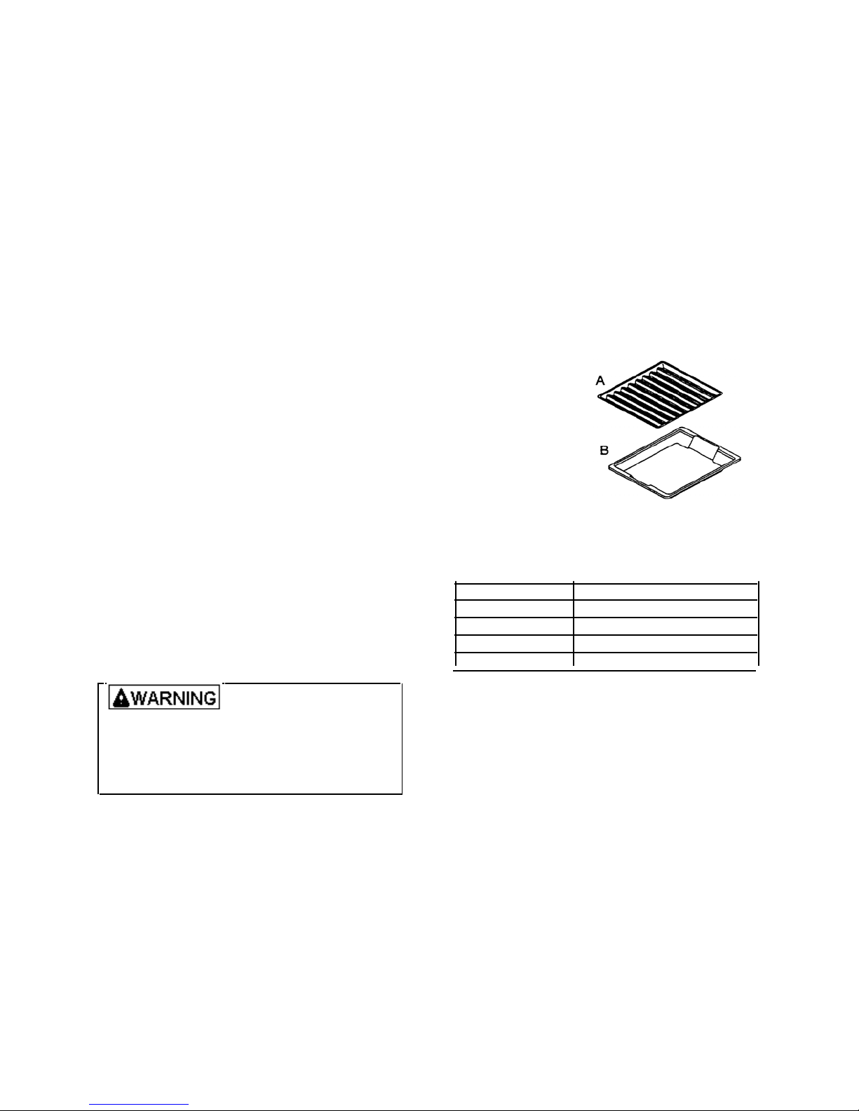
PROGRAMMING INSTRUCTIONS
Delayed Baking
Set oven to begin and end baking at later time.
Range control automatically calculates starting time.
1. Place food in oven.
2. Press STOP TIME pad.
• Current time of day appears in display.
3. Press + or - pad until desired stop time displays.
• Stop time can be set 11 hours 50 minutes ahead
of current time of day.
4. Press BAKE TIME pad.
5. Press + or - pad until desired baking time
displays.
• 10 minimum baking time.
6. Press BAKE pad.
7. Press + or - pad until desired temperature is
displayed.
• Temperature can be set from 170°F to 550°F in
5° increments.
• Electronic range control calculates start time.
• When start time is reached “DELAY” no longer
displays and “ON” displays.
• To view stop time, press and hold STOP TIME
pad.
• When baking time has elapsed, end of cycle
signal sounds, oven automatically turns off and
display returns to time of day. Oven signal
sounds 3 times, then once every 3 seconds for 5
minutes or until OFF/CANCEL pad is pressed.
To Cancel Remaining Baking Time
press OFF/CANCEL pad.
Prepare for Broiling
To avoid risk of fire, do not
line the broiler grid with foil.
• Foil may trap grease on top
of grid close to burner causing a fire.
• Never leave oven unattended while broiling.
Overcooking may result in a fire.
Broiling Tips
• Remove excess fat from meat before broiling. Cut
edges of meat to prevent curling.
• Place food on a cold ungreased broiling pan. If
pan is hot, food sticks.
• All food except fish should be turned at least one
time. Begin broiling with skin side down,
• Season meat after it has browned
• Broiling does not require preheating.
• Begin broiling using suggested rack levels in
Broil Guide .section to test broiler results. If food
is not brown enough, broil on a higher rack
position. If food is too brown, broil on a lower
rack position.
Infrared Broiling System
Infrared Broiling System generates immediate,
intense heat using a special screen. This screen
focuses heat directly on the food; searing in natural
juices and providing restaurant quality, charbroiled
flavor.
1. Center food on broiler grid and pan, and place on
rack in oven.
• Oven door should be closed.
A --- Broiler Grid
B --- Broiler Pan
2. Push BROIL pad.
3. Press + to set HI
broil or - pad to set lower broil temperature
• Temperature sets to HI or from 170°F to 550°F.
Broiler Setting Flame
HI Broiling red meats
545 Broiling pork
525 Broiling poultry
475 Broiling seafood
425 Broiling fruits and vegetables
400 and below Toasting and warming breads
4. Press OFF/CANCEL pad when finished.
Check Broiler Flame
Allow no more than 40--60 seconds before burner
ignites and flame is seen. If burner does not ignite,
press OFF/CANCEL pad. If burner repeatedly fails to
ignite within 40--60 seconds contact an authorized
servicer.
Hold
The hold feature holds the oven temperature at a low
temperature for 1 hour to keep food warm.
1. Press BAKE pad.
2. Press - pad until 170°, then HLD is displayed.
3. Press OFF/CANCEL pad when finished.
• Remove food from oven when broiling time has
elapsed. Food left in oven can overcook.
39
Page 40
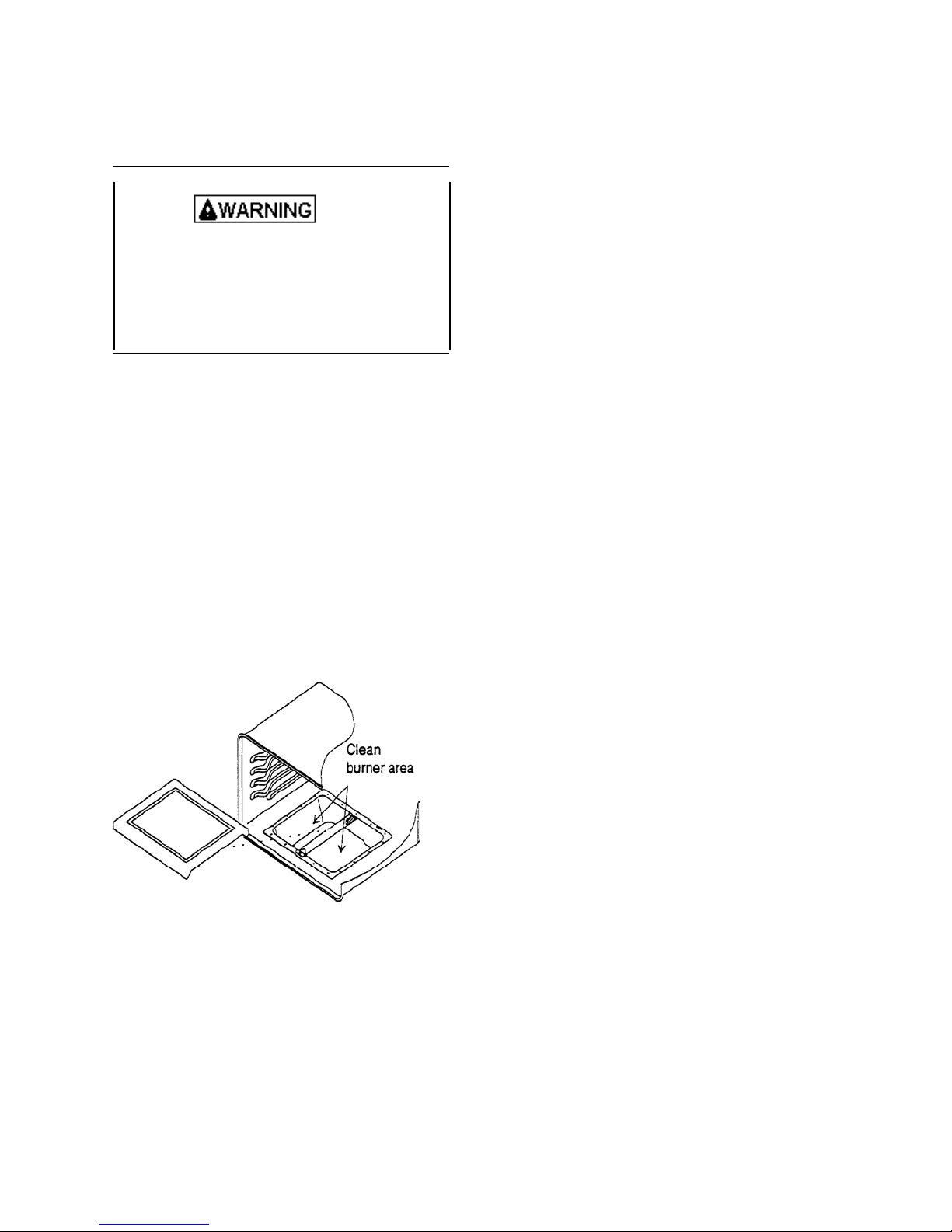
PROGRAMMING INSTRUCTIONS
Prepare for Self-Clean and Delayed Self-Clean
Cycle
To avoid risk of
personal injury, do not touch oven
vents or area around vents during self-cleaning.
These areas can become hot enough to cause burns.
To avoid risk of smoke damage or fire, clean excess
spills from oven interior.
• A small amount of smoke is normal when cleaning.
Excess smoke may indicate a faulty gasket or too
much food residue has been left in oven. Move
birds and small animals susceptible to fumes or
smoke to another room.
• Do not use cleaning cycle if oven light cover is not
properly in place.
• Remove oven racks and all baking utensils from
oven.
Clean Burner Area
Wear hand protection to avoid injury from sharp edges.
1. Pull oven bottom forward and lift out.
2. Wipe out burner area around burner with cloth and
warm soapy water.
3. Dry area thoroughly. Replace oven bottom.
Self-Cleaning
Self-clean feature uses high oven temperature to clean
oven interior. Only one oven can be cleaned at a time.
1. Prepare oven for self-cleaning.
2. Press CLEAN pad.
3. Press + or - pad to adjust desired amount of
cleaning time.
• Increase or decrease cleaning time by 5 minute
increments.
• Clean can be set from 2 to 4 hours. Minimum
recommended cleaning time is 3 hours.
• “LOCK” flashes while oven door is locking and
remains in display while door is locked.
• Oven begins to clean automatically.
4. Press OFF/CANCEL pad when finished.
• After oven has cooled to a safe temperature,
“LOCK” no longer displays and door is
unlocked.
Delayed Self-Clean Cycle
Self-clean feature uses high oven temperature to clean
oven interior. Set oven to begin and end cleaning at
later time. Control calculates back from end time to
determine starting time. Only one oven can be cleaned
at a time.
1. Prepare oven for self-cleaning.
2. Press CLEAN pad.
3. Press + or - pad to adjust desired amount of
cleaning time.
• Increase or decrease cleaning time by 5 minute
increments.
• Clean can be set from 2 to 4 hours. Minimum
recommended cleaning time is 3 hours.
4. Press STOP TIME pad.
5. Press + or - pad until desired stopping time appears
in display.
• Starting time is automatically calculated back
based on amount of cleaning time and stop time.
Oven begins to clean automatically.
• “LOCK” flashes while oven door is locking and
remains in display while door is locked.
• To view remaining cleaning time, press and hold
CLEAN pad.
• To view calculated stop time, press and hold
STOP TIME pad.
6. Press OFF/CANCEL pad when finished.
• After oven has cooled to a safe temperature,
“LOCK” no longer displays and door is
unlocked.
40
Page 41

Interrupt Self-Clean Cycle
1. Press OFF/CANCEL pad.
2. After oven has cooled to a safe temperature, door
can be opened.
Adjusting Oven Temperature
Oven temperature has been factory calibrated and
tested. In the unlikely event that oven consistently
overcooks or undercooks food, oven temperature can be
adjusted.
1. Press BAKE pad.
2. Press + until an oven temperature greater than
500°F shows in display.
3. Immediately press and hold BAKE pad until “00"
appears in display, approximately 5 seconds.
4. To decrease oven temperature (for cooler oven),
press - until negative numbers appear. Oven can be
adjusted from -05° to - 35° lower. To avoid overadjusting oven move temperature -5° each time.
5. To increase oven temperature (for a warmer oven)
press + until positive numbers appear. Oven can be
set from 05° to 35° higher. To avoid over adjusting
oven, move temperature 5° each time.
6. Press 0FF/CANCEL pad. Temperature adjustment
will be retained even through a power failure.
Service Tones and Codes
Electronic range control has a self-diagnostic system.
Self-diagnostic system sounds a series of short, rapid
beeps and shows an “F-code” in display when there is a
problem. When electronic range control signals a
problem, follow steps listed below.
1. Record “F-code” shown.
• See, DIGIT FAILURE DISPLAY in
“Warnings and Failure Codes” section.
2. Disconnect electrical supply.
• Pressing OFF/CANCEL pad or disconnecting
electrical supply may eliminate “F-code”. If
failure continues, contact an authorized servicer.
3. Contact an authorized servicer to check range.
41
NOTES:
Page 42

TESTING PROCEDURES
Service Information
Electronic Range Control (ERC) operates in
conjunction with a transformer/relay board 1, relay
board 2, and oven temperature sensor(s) to control all
bake, broil, and self-clean functions.
The ERC is connected to a mylar control panel
incorporating minute timer, clock, stop time, oven light,
cancel, bake, bake time, broil, and clean. Slew pads are
used to set times and temperatures.
The mylar control panel provides direct input to the
ERC to control all functions.
The ERC display consists of two digital readouts which
displays all timing functions, and all temperature
functions.
The transformer/relay board for upper oven consists of
oven light, bake, broil, door lock, and double line break
relays controlled by the ERC, and a step down
transformer with two secondary windings which
convert 120 VAC input to filament voltage (3.2--4.2
VAC) to power the ERC display.
The relay board for lower oven consists of bake, broil,
door lock, and double line break relays controlled by
the ERC.
Oven temperature sensor 1 is mounted in the upper
oven cavity and connected to the J4 connector on the
rear of the ERC. Oven temperature sensor 2 is mounted
in the lower oven cavity and connected to the J6
connector on the rear of the ERC. As the oven
temperature increased, the sensor resistance also
increases. The ERC converts this resistance to a
corresponding temperature readout and cycles the
relay(s) to maintain the desired temperature setting.
The ERC is also capable of sensing certain failure
conditions which can occur in the oven temperature
sensor(s), the self clean latch switch(es) the adaptor
board or the ERC itself. If the ERC senses a failure,
power will be removed from the relays, an alarm will
sound and a failure code will be displayed.
Each major component of the ERC system is serviced
as a separate part. However, each component and
related wire harness must be tested prior to replacing an
individual component.
Quick Test Procedure
“Quick Test” Mode for Electronic Range Control
Follow procedure to use the quick test mode. Entries
must be made within 32 seconds of each other or the
control will exit the quick test mode. The quick test
mode cannot be reactivated until power is disconnected
from oven, and must be accessed with in 5 minutes of
powering up.
NOTE: To enter Quick Test mode, this must be the
first key pad entered after power is applied.
1. Apply power to oven press and hold BAKE TIME
(upper oven) pad for 5 seconds.
2. Display will read the following:
Pad Response
CLEAN Double Line Break (DLB) on
BAKE DLB and Bake on
BROIL DLB and Broil on
STOP TIME Panel light and beeper on
BAKE TIME Displays manufacturer code and
sensor readings “000" = open sensor
TIMER Displays dashes
CLOCK All display segments illuminated
OVEN LIGHT Oven light on
CANCEL Exit Quick test
SLEW Sequences through display segments
ERC Warnings and Failure Codes
The ERC is capable of detecting certain failures within
the ERC, along with oven temperature sensor and self
clean door latch switch.
The warning and failure codes which may appear on the
display:
ERC will flash “door”, if one full door lock cycle
has not been completed within 60 seconds of
energizing the door lock relay.
DIGIT FAILURE DISPLAY
F1 control malfunction - Replace ERC
F2 oven over temperature - Check sensor wiring,
sensor, and temperature limiter
F3 open sensor or sensor circuit - Check sensor
resistance and wiring
F4 shorted sensor or sensor circuit - Check sensor
resistance and wiring
F7 shorted input key - verify control panel to p.c.
board connection, test control panel continuity,
replace control panel
F9 failure of door lock switch sensing with door
unlocked - Check latch switch, door motor, check
plunger switch, and wiring.
FF failure of door lock switch sensing with door locked
- Check latch switch, door motor, check plunger
switch, and wiring
42
Page 43

TESTING PROCEDURES
Temperature Calibration Offset
The ERC incorporates ± 35°F calibration offset
capabilities for the oven. This adjustment will not
effect the cleaning cycle temperature and will remain in
memory if power is interrupted. Follow the procedures
as listed to calibrate oven.
1. Press BAKE pad.
2. Press + until an oven temperature greater than
500°F shows in display.
3. Immediately press and hold BAKE pad until “00"
appears in display, approximately 5 seconds.
4. To decrease oven temperature (for cooler oven),
press - until negative numbers appear. Oven can be
adjusted from -05° to -35° lower. To avoid overadjusting oven move temperature -5° each time.
5. To increase oven temperature (for a warmer oven)
press + until positive numbers appear. Oven can be
set from 05° to 35° higher. To avoid over adjusting
oven, move temperature 05° each time.
6. Press OFF/CANCEL pad. Temperature adjustment
will be retained even through a power failure.
Function Switch Connection Check Procedure
The Quick-Test mode can be used to verify relay
operation on the transformer/relay board. If the relay
engages (clicks) during Quick-Test mode it is generally
operative.
Transformer/Relay Board 1
The relays for door lock, oven light, bake, and broil, are
controlled by approximately a 24 VDC signal from the
ERC. Input voltage is 102 - 132 VAC.
Testing of the relays is with voltage applied to oven
after attaching voltmeter leads to appropriate terminals.
Double Line Break --K6
Drive voltage (24 VDC) indicated at J1 connector Pin 1
and 3.
1. Turn off power to oven.
2. Attach voltmeter lead to E1 connector on relay
board.
3. Attach voltmeter lead to E18 connector on relay
module.
4. Turn on power and touch bake, broil or convection.
5. If 24 VAC is indicated, the double line break relay
is closing. Otherwise, replace the transformer/ relay
board.
Bake Relay --K4
Double line break relay okay. Drive voltage at J1
connector pins 3 and 5.
1. Turn off power to oven.
2. Attach voltmeter lead to E18 connector on relay
board.
3. Attach voltmeter lead to E11 (BK) connector on
relay module.
4. Turn on power and touch the bake pad.
5. If 24 VAC is indicated, bake relay is operating.
Broil Relay --K5
Double line break relay okay. Drive voltage at J1
connector pins 3 and 6.
1. Turn off power to oven.
2. Attach voltmeter lead to E18 connector on relay
module.
3. Attach voltmeter lead to E12 (BR) connector on
relay module.
4. Turn on power and touch broil pad.
5. If 24 VAC is indicated broil relay is operating.
Oven Light Relay --K10
Drive voltage at J1 connector pins 1 and 4.
1. Turn off power to oven.
2. Attach voltmeter lead to E3 (neutral) connector on
relay module.
3. Attach voltmeter lead to E17 connector on relay
module.
4. Turn on power and touch oven light pad.
5. If 120 VAC is indicated, oven light relay is
operating.
Door Lock Relay --K3
Double line break relay okay. Drive voltage at J1
connector pins 1 and 9.
1. Turn off power to oven.
2. Attach voltmeter lead to E3 (neutral) connector on
relay module.
3. Attach voltmeter lead to E8 connector on relay
module.
4. Turn on power and program cleaning cycle
operation.
5. Two indications will be present during this test.
• 120 VAC will be present when the lock
assembly is being engaged.
• 0 VAC is indicated when the door is locked and
cleaning cycle is operational.
Display (Filament) Voltage
1. Turn power on, turn meter to VAC scale.
2. Touch meter lead to J1-1 terminal.
3. Touch meter lead to J1-14 terminal
4. Meter should indicate 3.2 VAC.
43
Page 44

TESTING PROCEDURES
Relay Board 2
The relays for oven light, bake, broil, convection
element, convection fan and double line break are
controlled by approximately 24 VAC signal from ERC.
Input voltage is 102 -- 132 VAC.
Testing of the relays is with voltage applied to oven
after attaching voltmeter leads to appropriate terminals
NOTE: If bake, broil, or convection do not work, the
first test would be the relay for double line break.
Bake Relay --K2
Double line break relay okay. Drive voltage at J1
connector pins 4 and 5.
1. Turn off power to oven.
2. Attach voltmeter lead to gray wire connection on
double line break relay.
3. Attach voltmeter lead to E3 (BA) connector on
relay.
4. Turn on power and touch the bake pad.
5. If 24 VAC is indicated bake relay is operating.
Broil Relay --K3
Double line break relay okay. Drive voltage at J1
connector pins 3 and 5.
1. Turn off power to oven.
2. Attach voltmeter lead to gray wire connection on
double line break relay.
3. Attach voltmeter lead to E6 (BR) connector on relay
module.
4. Turn on power and touch broil pad.
5. If 24 VAC is indicated broil relay is operating.
Door Lock Relay --K4
Double line break relay okay. Drive voltage at J1
connector pins 1 and 7.
1. Turn off power to oven.
2. Attach voltmeter lead to E3 (neutral) connector on
transformer/relay board 1.
3. Attach voltmeter lead to E2 connector on relay
module.
4. Turn on power and program cleaning cycle
operation.
5. Two indications will be present during this test.
• 120 VAC will be present during the lock
assembly is being engaged.
• 0 VAC is indicated when the door is locked and
cleaning cycle is operational.
44
Page 45
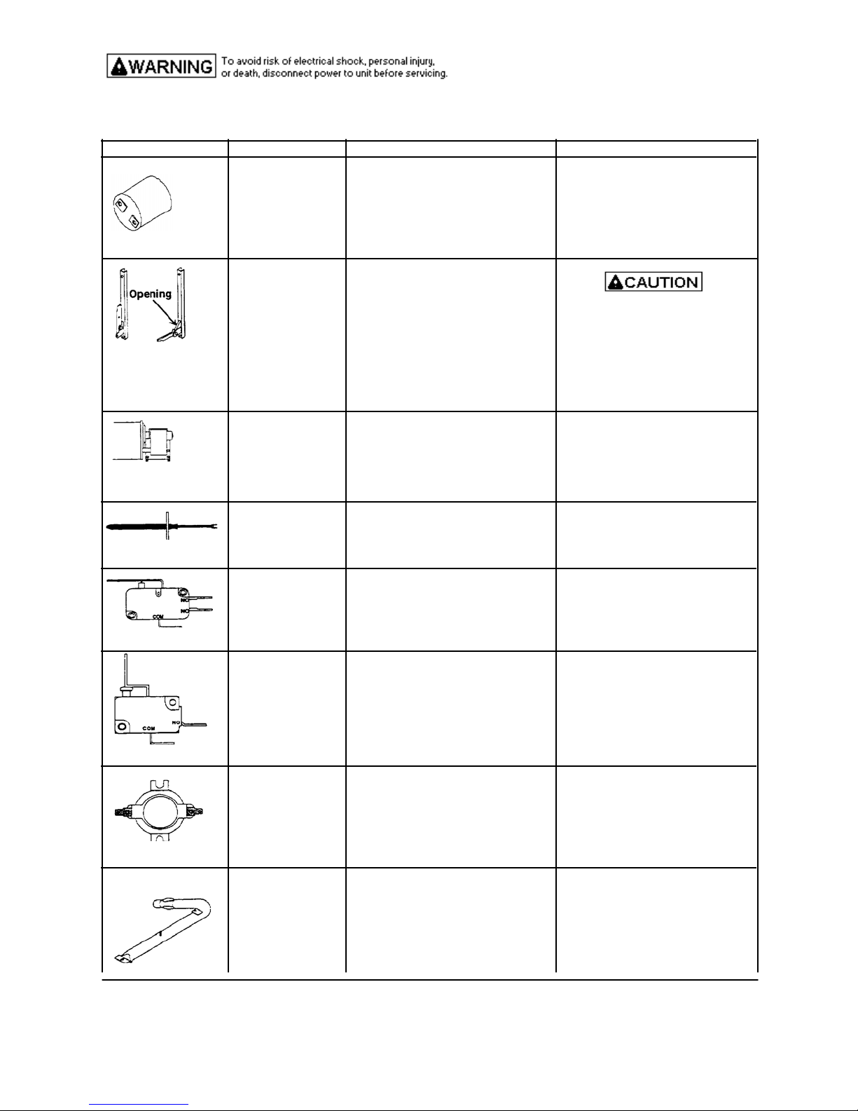
COMPONENT TESTING INFORMATION
Illustration Component Test procedure Results
voltage is present at oven light
rear of unit and guide hinge out Hinge can snap and pinch hands
through frame opening or storage or fingers.
Blower motor Verify supply voltage. 120VAC
chassis.
Bake Burner Verify gas is supplied.
Oven light socket
check wiring.
Hinge Carefully open the hinge fully, &
hinge. Slide hinge top toward when oven door is removed.
terminals, and are not shorted to
Heraeus sensor Measure resistance Approximately 1100Ω at room
Door lock switch Switch connections in following Normally open
or light switch positions:
Sail switch Switch connections in following Normally open
Engaged Com-NO=Closed, ComNC=Open
Controls Verify proper operation. Normally open
Test continuity of receptacle Indicates continuity with bulb
terminals. screwed in.
Measure voltage at oven light 120 VAC, see wiring diagram for
terminal identification If no
insert a wooden dowel or screw-
driver bit into opening. Remove
top and bottom screws securing Do not place hands in hinge area
drawer
Disconnect and check continuity of Continuity
motor at the terminals, and verify
temperature.
Unlocked Com-NO=Open, Com-NC=Closed
Locked Com-NO=Closed, Com-NC-Open
positions:
Not engaged Com-NO=Open, ComNC=Closed
31833001 Control limi Opens at 145°F, Closes at 185°F
042056 Fan switch 1-2 (NO) Opens at 120°F, Closes at 150°F
1-3 (NC) Opens at 150°F, Closes at 120°F
Orifice adjusted for Natural or LP.
Check for obstructions or
contamination in ports.
w
45
Page 46
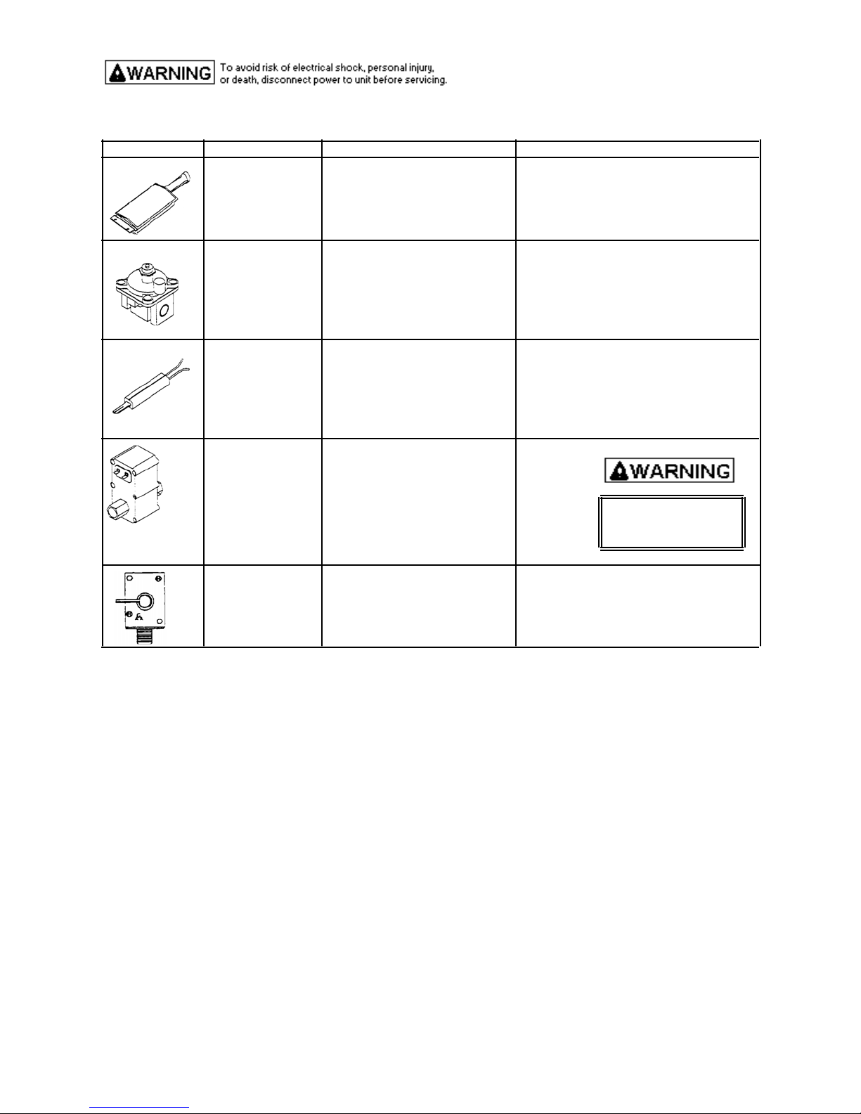
COMPONENT TESTING INFORMATION
Illustration Component Teat Procedure Result
circuit
Broil Burner Verify gas is supplied.
Proper orifice installed for
Natural or LP.
Check for damage to screen. Replace if punctured or torn.
Pressure regulator Verify gas pressure (WPC). 5" Natural
If on LP service verify gas 10" LP/Propane
supply conversion.
Norton Ignitor Test for voltage at terminals. 120 VAC
Test for the amount of 3.2 --3.6 Amps
amperage in the circuit
(Ignitor may glow but not
have sufficient amperage to
open valve).
Gas valve Disconnect wiring to valve
Measure resistance on bake
circuit. Continuity Do not attempt to open
Measure resistance on broil valve with 120 VAC
Shut off valve Check to verify gas supply is
turned on.
Continuity
46
Page 47
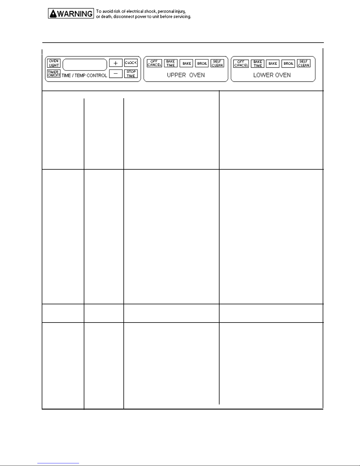
C OMPONENT TESTING INFORMATION
ECR mylar touch system
Illustration Component Test Procedure Results
See Illustrations Mylar touch F1 - Control malfunction. Test mylar touch pad.
above system F2 - Oven over temperature. Check sensor wiring, sensor, and
temperature limiter.
F3 - Open sensor or sensor circuit Check sensor resistance and wiring.
F4 - Shorted sensor or sensor circuit Check sensor resistance and wiring.
F7 - Shorted input key. Verify mylar switch connections, replace
mylar touch switch.
F9 - Door lock or door lock circuitry Check latch switch.
malfunction (door unlocked)
FF - Door lock or door lock circuitry Check latch switch
malfunction (door locked)
Door - Lock status is not sensed within Verify operation of door latch switches.
ERC control Oven Press Bake While increasing or decreasing oven
temperature Press + slew pad until an oven temperature, this does not affect selfadjustment temperature greater than 500° shows cleaning temperature.
` To increase oven temperature (for
ERC control Twelve hour Control will automatically cancel any
off baking operation and remove all relay
ERC control Child lock out This is a safety feature that can be used
90 seconds of energizing door lock relay.
on display.
Immediately press and hold BAKE until
“00" appears in display, approximately
5 seconds.
To decrease oven temperature (for a
cooler oven), press - slew pad until
negative numbers appear. Oven can be
adjusted from -5° to -35° lower.
To avoid over adjusting oven move
temperature -5° each time.
warmer oven), press + slew pad until
positive numbers appear. Oven can be
adjusted 5° to 35° higher. To
avoid overadjusting oven move
temperature 5° each time.
Press OFF / CANCEL. Temperature
adjustment will be retained even though
power failure.
drives 12 hours after the last pad touch.
to prevent children from accidentally
programming the oven. If disables the
electronic oven control. Press and hold
BAKE and BAKE TIME for approxImately 5 seconds. “Off” will display
where the temperature normally appears.
To reactivate the control, press and hold
BAKE and BAKE TIME for 5 seconds.
Child lockout features must be reset after
a power failure.
47
Page 48
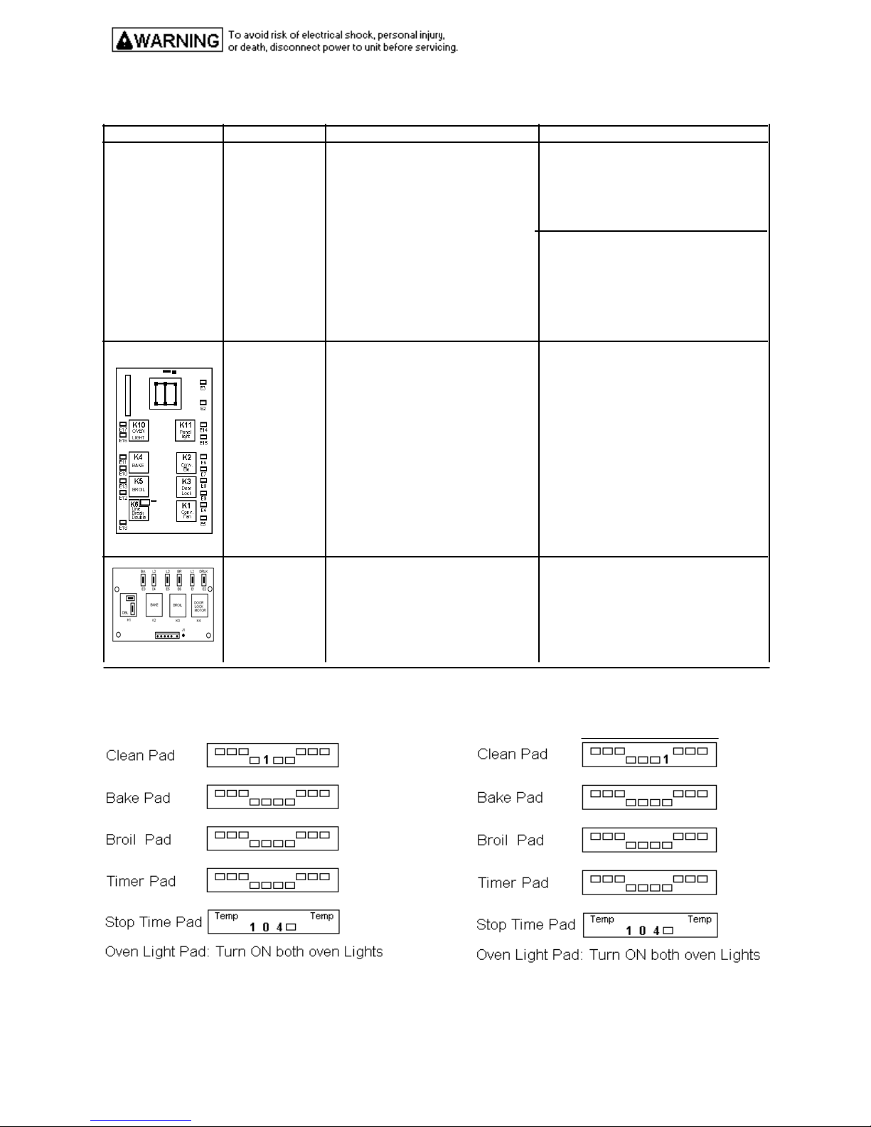
COMPONENT TESTING INFORMATION
Illustration Component Teat Procedure Results
ERC Controlled Quick test mode Press and hold Bake Time pad for
5 seconds within the first 5 minutes
of power up. (This must be the first
pad touhed.) Pressing each pad will
force a response from control,
releasing the pad ends the response.
Entries on control pad must be
within 32 seconds of each other or
control will exit mode. Mode can
exited by pressing Off/Cancel.
See Quick Test Mode Display
below.
Relay Board Listen for relay to actuate. If relay does not actuate, verify power
to
Verify input and output power. relay board (120 VAC)
Relay Board Listen for relay to actuate. If relay does not actuate, verify power
to
Verify input and output power relay board (120 VAC).
Quick Test Mode Display;
Upper oven Lower oven
Clean Double line break (DLB) on
Bake DLB and Bake on
Broil DLB and Broil on
Stop Time Panel light and beeper on
Bake Time Displays checks and sensor readings
Timer Displays dashes
Clock Display on full
Oven Light Oven light on
Slew pads Sequences thru display segments
Cancel Exits quick test mode
48
Page 49
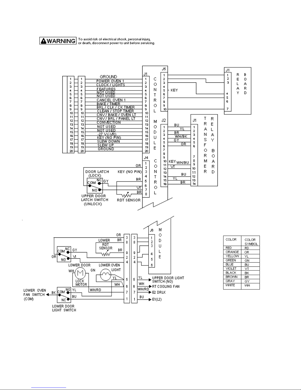
COMPONENT TESTING INFORMATION
49
Page 50
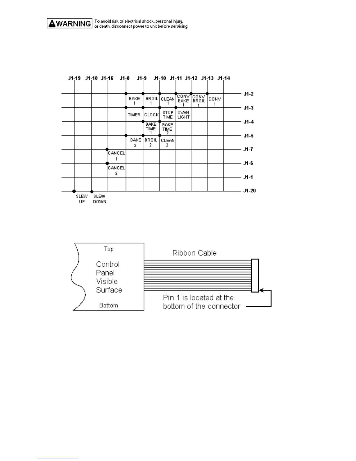
COMPONENT TESTING INFORMATION
Continuity is indicated as 100Ώ and below. Each pad must be pressed to perform the following test.
Switch Matrix
Relay Drive Requirements
Relay drive requirements are defined as a percentage of on time based on a 60 second cycle.
Bake 100% bake
Broil 100% broil
Clean Stage 1 - 100% broil, 0% bake, for 30 minutes
Stage 2 - 0% broil, 100% bake
50
Page 51

SCHEMATIC WIRING DIAGRAM
VGDO 271 BUILT-IN GAS 27” W. DOUBLE WALL OVEN
51
Page 52
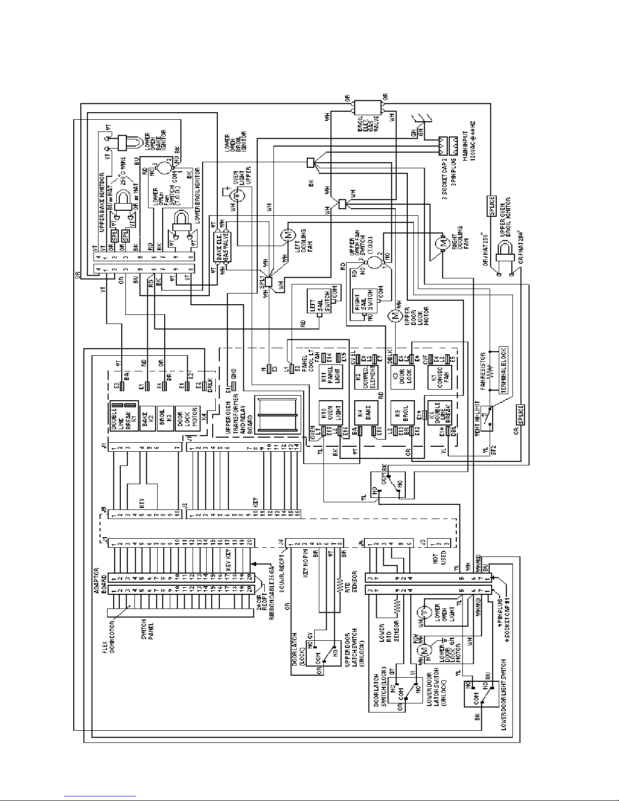
VGDO271 WIRING DIAGRAM BUILT-IN GAS 27” W. DOUBLE OVEN
52
 Loading...