

Page 1
Viking Range Corporation
111 Front Street
Greenwood, Mississippi 38930 USA
(662) 455-1200
For more product information,
call 1-888-VIKING1 (845-4641) or
visit the Viking web site
vikingrange.com
F20664D EN
(082012)
Built-In Electric Warming Drawers
(Indoor and Outdoor Models)
Viking Installation Guide
Page 2
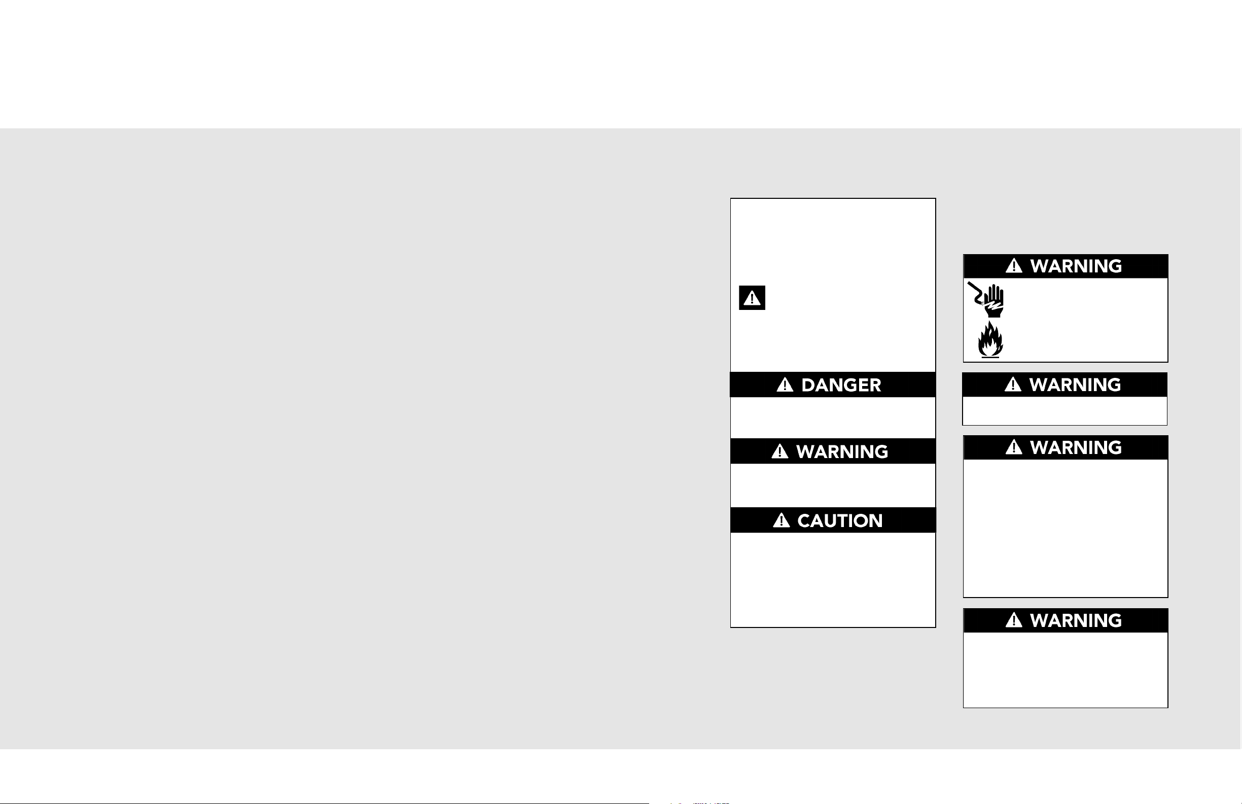
Table of Contents
Warnings & Important Safety Instructions _______________________________________________3
Dimensions _________________________________________________________________________4
Specifications _______________________________________________________________________6
Cutout Dimensions (VEWD/VEWDO) ___________________________________________________7
Cutout Dimensions (DFWD) ___________________________________________________________8
Electrical Requirements ______________________________________________________________9
General Information ________________________________________________________________10
Installation (VEWD/VEWDO) _________________________________________________________11
Custom Front (DFWD)_______________________________________________________________13
Final Preparation ___________________________________________________________________14
Performance Checklist ______________________________________________________________14
Service & Registration _______________________________________________________________15
IMPORTANT– Read and Follow!
Your safety and the safety of others is
very important.
We have provided many important safety
messages in this manual and on your
appliance. Always read and obey all
safety messages.
This is the safety alert symbol. This
symbol alerts you to hazards that
can kill or hurt you and others.
All safety messages will be preceded by
the safety alert symbol and the word
“DANGER,” “WARNING” or “CAUTION.”
These words mean:
Hazards or unsafe practices
which WILL result in severe personal
injury or death
Hazards or unsafe practices
which COULD result in severe personal
injury or death
Hazards or unsafe practices which
COULD result in minor personal injury or
property damage.
All safety messages will identify the
hazard, tell you how to reduce the chance
of injury, and tell you what can happen if
the instructions are not followed.
• Before beginning, please read these
instructions completely and carefully.
• DO NOT remove permanently affixed
labels, warnings, or plates from product.
This may void the warranty.
• All local and national codes and ordinances
must be observed. Installation must
conform with local codes, or in the absence
of codes, the National Electrical Code,
ANSI/NFPA70 - latest edition.
• The installer must leave these instructions
with the consumer who should retain for
local inspector’s use and for future
reference.
In Canada: Installation must be in accordance
with the current CSA C22.1 Canadian
Electrical Codes Part 1 and/or local codes.
FIRE AND ELECTRICAL
SHOCK HAZARD
To reduce the risk of electric
shock and fire, DO NOT use a
flexible power-supply cord with
this appliance.
For outdoor installation, installer must
install a ground fault interrupt.
Make sure that incoming voltage is the
same as unit rating. An electric rating plate
specifying voltage, hertz, wattage, amps,
and phase is attached to the product.
Wiring the warming drawer with more
voltage than it is rated for may cause
severe damage to the thermostat,
element, and other components. Wiring
the warming drawer with less voltage than
it is rated for may cause significant
decrease in performance.
To reduce the risk of fire, electric shock, or
injury to persons, installation work and
electrical wiring must be done by qualified
people in accordance with all applicable
codes and standards, including fire-rated
conditions.
2
3
Page 3
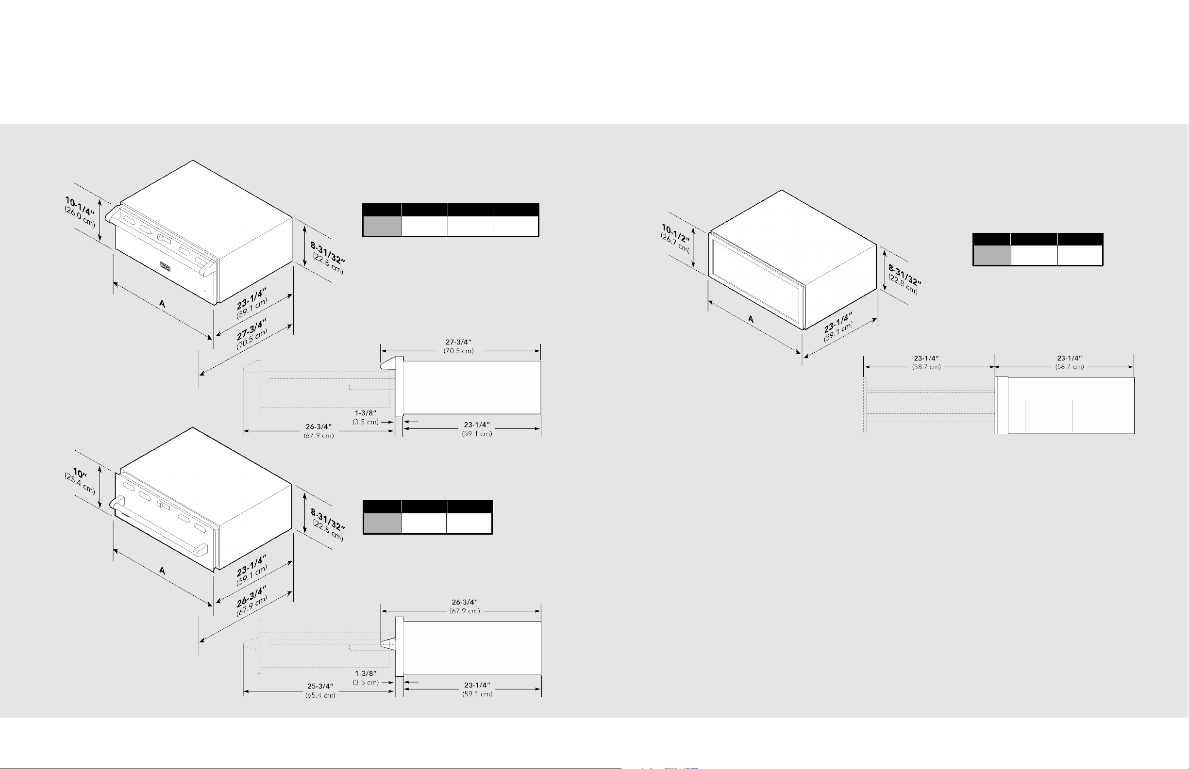
Dimensions - VEWD
4
Dimensions - DFWD
5
Custom
VEWD527/530/536
Custom Front
DFWD171/101
DFWD171 DFWD101
Overall
width A
26”
(66.0 cm)
29”
(73.7 cm)
VEWD527 VEWD530 VEWD536
Overall
width A
26-1/2”
(67.3 cm)
29-1/2”
(74.9 cm)
35-3/8”
(89.9 cm)
Outdoor
VEWDO530/536
VEWD530 VEWD536
Overall
width A
29-1/2”
(74.9 cm)
35-1/4”
(89.5 cm)
Page 4
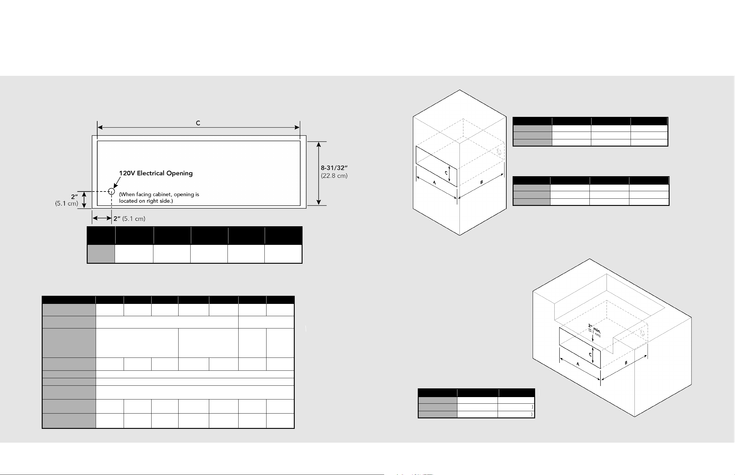
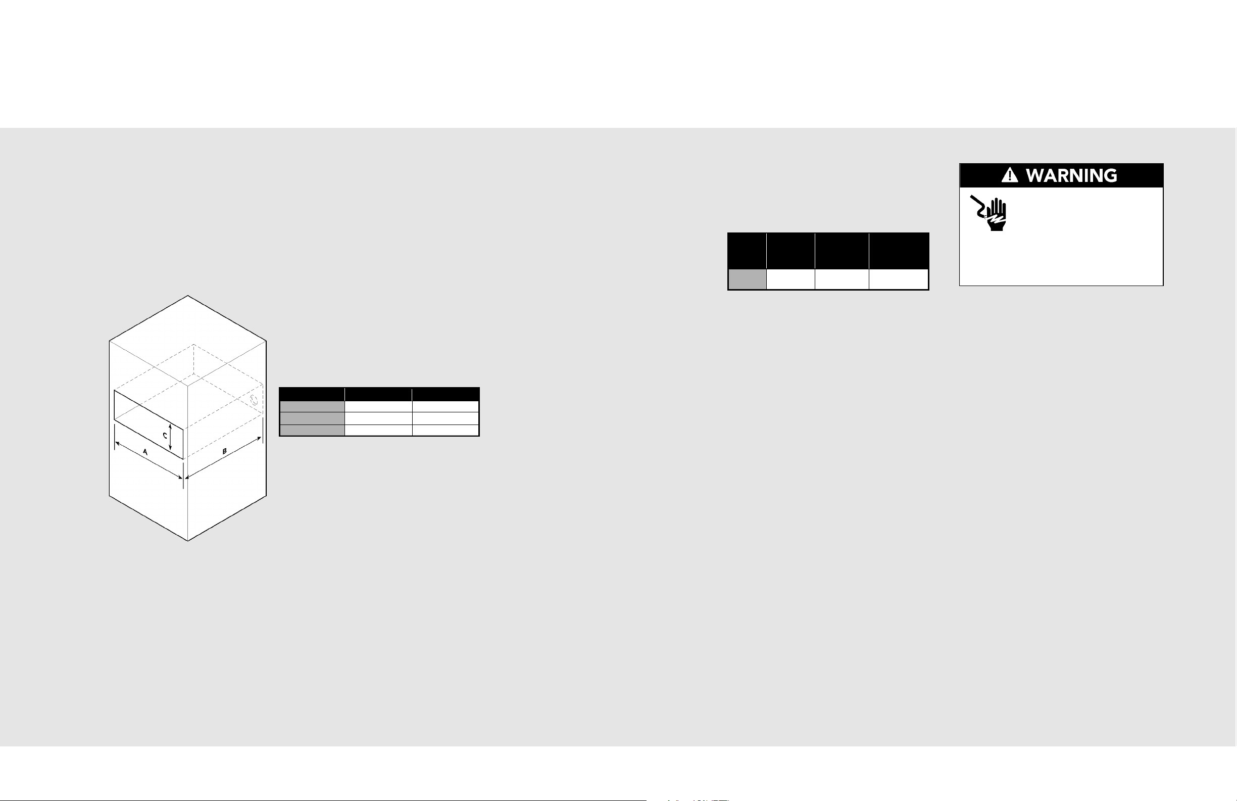
Cutout Dimensions - VEWD/VEWDO
7
VEWD527 VEWD530 VEWD536
Cutout width (A) 25-1/4” (64.1 cm) 28-1/4” (71.8 cm) 34” (86.4 cm)
Cutout depth (B) 23-1/2” (59.7 cm) 23-1/2” (59.7 cm) 23-1/2” (59.7 cm)
Cutout height (C) 9-1/4” (23.5 cm) 9-1/4” (23.5 cm) 9-1/4” (23.5 cm)
VEWDO530 VEWDO536
Cutout width (A) 28-1/4” (71.8 cm) 34” (86.4 cm)
Cutout depth (B) 23-1/2” (59.7 cm) 23-1/2” (59.7 cm)
Cutout height (C) 9-1/4” (23.5 cm) 9-1/4” (23.5 cm)
Outdoor
Indoor
Note: For Outdoor Models, seal around drawer opening with silicon caulk that is provided.
Specifications
6
Flush Mount Option:
Note: To install the warming drawer in a flush mount application, a flush mount
accessory kit is required and sold separately.
VEWD527 VEWD530 VEWD536
Cutout width (A) 26-15/16” (68.4 cm)29-15/16” (76.0 cm) 35-5/8” (90.5 cm)
Cutout depth (B) 25-3/8” (64.5 cm) 25-3/8” (64.5 cm) 25-3/8” (64.5 cm)
Cutout height (C) 10-5/8” (27.0 cm) 10-5/8” (27.0 cm) 10-5/8” (27.0 cm)
Description
VEWD527 VEWD530 VEWD536 VEWDO530 VEWDO536 DFWD171 DFWD101
Overall width 26-1/2”
(67.3 cm)
29-1/2”
(74.9 cm)
35-3/8”
(89.9 cm)
29-1/2”
(74.9 cm)
35-1/4”
(89.5 cm)
26”
(66.0 cm)
29”
(73.7 cm)
Overall height
(from bottom)
10-1/4” (26.0 cm) 10-1/2” (26.7 cm)
Overall depth (from rear)
To end of handle
With drawer fully
extended
27-3/4”(70.5 cm)
51-3/8” (130.5 cm)
26-3/4”(67.9 cm)
50-3/8” (128.0 cm)
N/A N/A
Interior width 17-1/4”
(43.8 cm)
20-1/2”
(52.1 cm)
25”
(63.5 cm)
20-1/2”
(52.1 cm
25”
(63.5 cm)
17-1/4”
(43.8 cm)
20-1/2”
(52.1 cm)
Interior height 6” (15.2 cm)
Interior depth 22-3/4” (27.8 cm)
Electrical
Requirements
Hard wire direct with separate 15 amp minimum 2-wire with ground circuit;
120 VAC/50-60 Hz
Max. Amp Usage 425 watts
3.6 amps
450 watts
3.8 amps
550 watts
4.6 amps
450 watts
3.8 amps
550 watts
4.6 amps
425 watts
3.6 amps
450 watts
3.8 amps
Approx. shipping wt. 80 lb.
(36 kg)
90 lb.
(40.5 kg)
110 lb.
(49.5 kg)
90 lb.
(40.5 kg)
110 lb.
(49.5 kg)
90 lb.
(40.5 kg)
110 lb.
(49.5 kg)
Rear View
VEWD/VEWDO/DFWD
VEWD527 DFWD171 VEWD530/
VEWDO530/
DEWD102
DFWD101 VEWD536/
VEWDO536
Overall
width C
24-7/8”
(63.2 cm)
24-7/8”
(63.2 cm)
27-7/8”
(70.8 cm)
27-7/8”
(70.8 cm)
33-5/8”
(85.4 cm)
Dimensions
Page 5
Electrical Requirements
Electrical shock hazard.
To avoid the risk of electrical
shock, personal injury or death;
verify electrical power is turned
off at the breaker box until the range is
installed and ready to operate, installation
by an authorized installer only.
9
Electrical Connection
VEWD527/
DFWD171
VEWD530/
VEWDO530
DEWD102
DFWD101
VEWD536/
VEWDO536
Max. amp
usage
425 watts
3.6 amps
450 watts
3.8 amps
550 watts
4.6 amps
Electrical Requirements
Check your national and local codes
regarding this unit. Hard wire direct with
seperate 120V/15 amp minimum 2-wire
wtih ground circuit. Maximum amp usage.
Note: Use copper conductors ONLY!
Grounding Instructions
This appliance must be connected to a
grounded metal, permanent wiring system,
or an equipment-grounding conductor
must be run with the circuit conductors and
connected to the equipment-grounding
terminal or lead on the appliance.
With the appliance positioned in front of
the cabinet opening, connect wire leads
extending from the power supply to the
terminal block of the unit. Make sure the
colored wires of the terminal block are
connected to the corresponding colored
wires extending from the power supply.
Cutout Dimensions - DFWD
8
DFWD171 DFWD101
Cutout width (A) 25-1/4” (64.1 cm) 28-1/4” (71.8 cm)
Cutout depth (B) 24” (61.0 cm) 24” (61.0 cm)
Cutout height (C) 9-1/4” (23.5 cm) 9-1/4” (23.5 cm)
Custom Front Models
Page 6
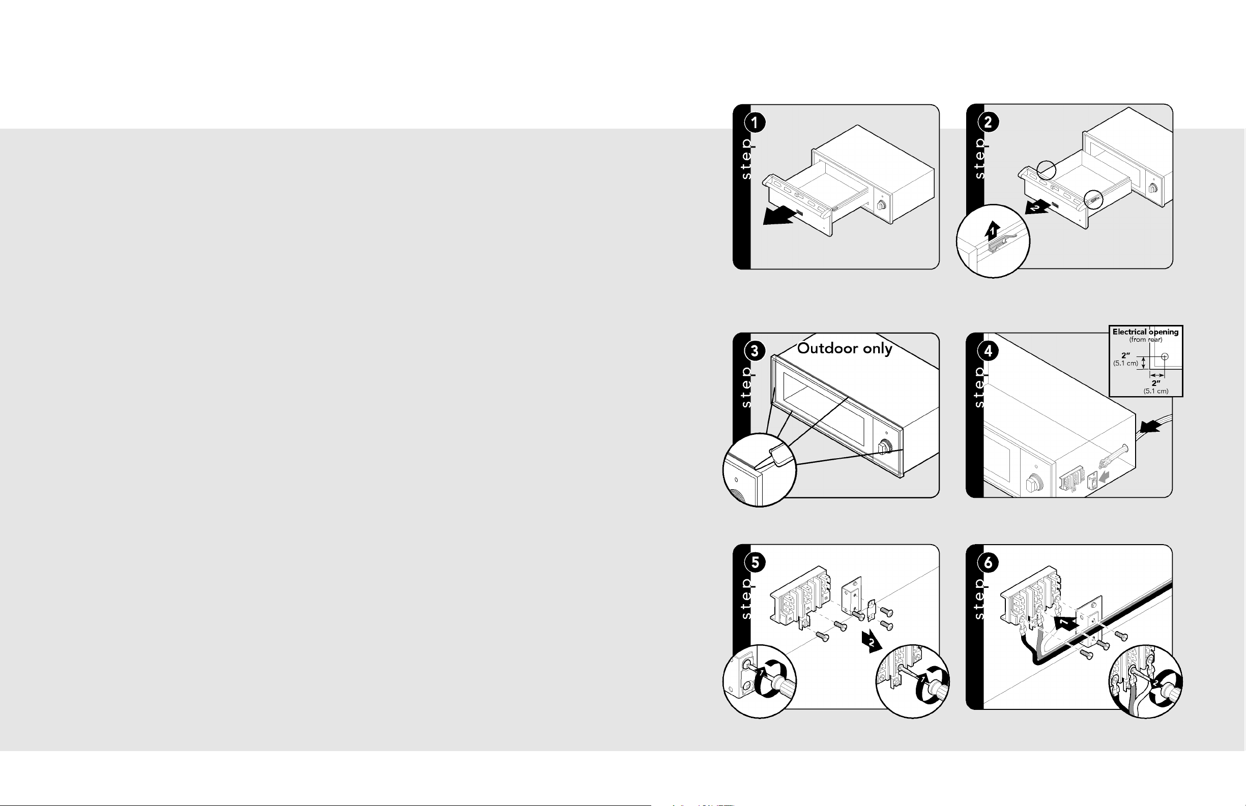
Installation - VEWD & VEWDO
11
Pull out warming drawer
pan until fully extended.
Slide finger along right and left side until you reach the
black hand latches (located at the front of the rails). Pull
up on both the right and left latches and pull out
drawer pan support.
Apply silicone caulk around the back
of the warming drawer trim.
Note: For outdoor models ONLY.
Feed supply cord up through
hole in rear of warming drawer.
Remove strain relief bracket and mounting
screws on the terminals.
Attach the white (neutral) and black (line) lead
terminals. Attach ground wire to the
center terminal.
General Information
10
• When installing this unit directly below
other units, only install with Viking builtin products.
• Remove warming drawer carefully from
carton. Remove all loose packaging and
accessories.
• It is the responsibility of the installer to
comply with local codes. If no local
codes are applicable, wire in accordance
with the National Electrical Code,
ANSI/NFPA 70 - latest edition.
• This appliance is not fused. Protect
with a proper sized fuse or circuit
breaker and a GFI for outdoor models.
• Line disconnect switch, circuit breaker,
GFI (for outdoor models) or
plug/receptacle of power cord
connection should be readily accessible
to the operator.
• Ground unit per applicable electrical
codes.
• Any installation not matching the
specifications discussed in these
instructions will void the manufacturer’s
warranty.
READ AND FOLLOW ALL WARNING
AND CAUTION INFORMATION
WHEN INSTALLING THIS APPLIANCE.
Moving, Handling and Unpacking
Remove and discard all packing materials,
including cardboard and tape on the
outside and inside of the warming drawer.
Some stainless steel parts may have a
plastic protective wrap which must be
peeled off. The interior should be washed
thoroughly with hot, soapy water to remove
film residues and any dust or debris before
being used, then rinsed and wiped dry.
Solutions stronger than soap and water are
rarely needed.
Page 7
12
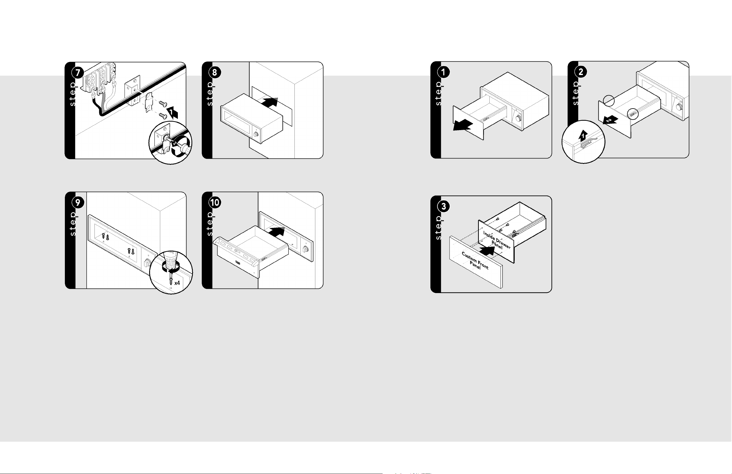
Push supply cord toward terminal
block to relieve strain, reattach supply cord strain relief
bracket over supply cord.
Slide cavity assembly into the cabinet opening.
Secure the warming drawer using four
#8 mounting screws (four screws provided).
Replace drawer assembly.
Installation - Custom Front DFWD
13
Pull out warming drawer pan until fully extended.
Slide finger along right and left side until you reach the
black hand latches (located at the front of the rails). Pull
up on both the right and left latches and pull out
drawer pan support.
Center the custom front on the inside drawer panel.
Attach the custom front with the six 5/8” screws provided.
Page 8

Final Preparation
14
Service & Registration
15
• All stainless steel body parts should be
wiped with hot, soapy water and with a
liquid cleaner designed for this material.
If buildup occurs, DO NOT use steel wool,
abrasive cloths, cleansers, or powders!
If it is necessary to scrape stainless steel
to remove encrusted materials, soak with
hot, wet cloths to loosen the material, then
use a wool or nylon scraper. DO NOT use
a metal knife, spatula, or any other
material tool to scrape stainless steel!
Scratches are almost impossible to
remove.
Only authorized replacement parts may be used in performing service on the appliance.
All servicing should be referred to a qualified technician.
Contact Viking Range Corporation, 1-888-VIKING1 (845-4641), for the nearest service parts
distributor in your area or write to:
VIKING RANGE CORPORATION
PREFERRED SERVICE
1803 Hwy 82W
Greenwood, Mississippi 38930 USA
Warming Drawer – The serial number and model number for your
appliance can be found by pulling drawer out until it stops and lifting
inner lining. Rating/Serial plate is located on the left, rear side.
Record the following information indicated below. You will need it if service is ever required.
Model number ____________________________________________________________________________________
Serial number _____________________________________________________________________________________
Date of purchase __________________________________________________________________________________
Date installed ______________________________________________________________________________________
Dealer's name _____________________________________________________________________________________
Address ___________________________________________________________________________________________
These installation instructions should remain with the unit for future reference.
 Loading...