

Page 1
VIKING MODEL VEV900
EXTERIOR MOUNTED BLOWER
FOR USE WITH VIKING VWH, VIH, VBCV, VICV AND DTWN
24" TO 42" WIDE, 18" HIGH RANGE HOODS
READ AND SAVE THESE INSTRUCTIONS
WARNING
TO REDUCE THE RISK OF FIRE, ELECTRIC
SHOCK, OR INJURY TO PERSONS, OBSERVE
THE FOLLOWING:
1. Use this unit only in the manner intended by the
manufacturer. If you have questions, contact the
manufacturer or your distributor.
2. Before servicing or cleaning unit, switch power off
at service panel and lock the service disconnecting means to prevent power from being switched
on accidentally. When the service disconnecting
means cannot be locked, securely fasten a prominent warning device, such as a tag, to the service
panel.
3. Installation work and electrical wiring must be done
by a qualified person(s) in accordance with all
applicable codes and standards, including firerated construction codes and standards.
4. Sufficient air is needed for proper combustion and
exhausting of gases through the flue (chimney) of
fuel burning equipment to prevent backdrafting.
Follow the heating equipment manufacturer's guideline and safety standards such as those published
by the National Fire Protection Association (NFPA),
and the American Society for Heating, Refrigeration and Air Conditioning Engineers (ASHRAE),
and the local code authorities.
WARNING
5. When cutting or drilling into wall, or ceiling, do not
damage electrical wiring or other hidden utilities.
6. Ducted fans must always be vented to the outdoors.
7. To reduce risk of fire, use only metal ductwork.
8. This unit must be grounded.
CAUTION
1. For general ventilating use only. Do not use to
exhaust hazardous or explosive material and vapors.
2. To avoid motor bearing damage and noisy and/or
unbalanced impellers, keep drywall spray, construction dust, etc. off power unit.
3. Please read specification label on product for
further information and requirements.
4. Electrical circuit, including speed control, (if used),
must be rated 6 AMPS minimum.
Blower Dimensions
28.251 x 24.75 x 7.17
SPECIFICATIONS
MODEL VOLTS AMPS CFM DUCT SIZE
VEV900 120 5.7 900 10 " DIA.
PLAN THE INSTALLATION
ALL INSTALLATIONS
1. Locate the blower so the length of the duct run and
number of elbows needed are kept to a minimum.
2. Where possible, blower should be centered between wall studs or roof rafters.
3. Avoid pipes, wires, or other ductwork that may be
running through the wall.
INSTALLER: Leave This Manual With The Homeowner
HOMEOWNER: Use And Care Information On Page 4
1
Page 2
11" dia.
hole
29½"
1¼"
dia. hole
127/8"
10¾"
25"
7¼"
91/8"
Wa l l S tud
Wa l l S tud
REMOVE
SIDING
8½"
Pilot
Hole
OUTSIDE - WALL VIEW
PREPARE THE INSTALLATION
20½"
11"
dia.
hole
103/8"
1¼"
dia. hole
8½"
20¾"
7¼"
91/8"
REMOVE
SHINGLES
Pilot
Hole
OUTSIDE - ROOF VIEW
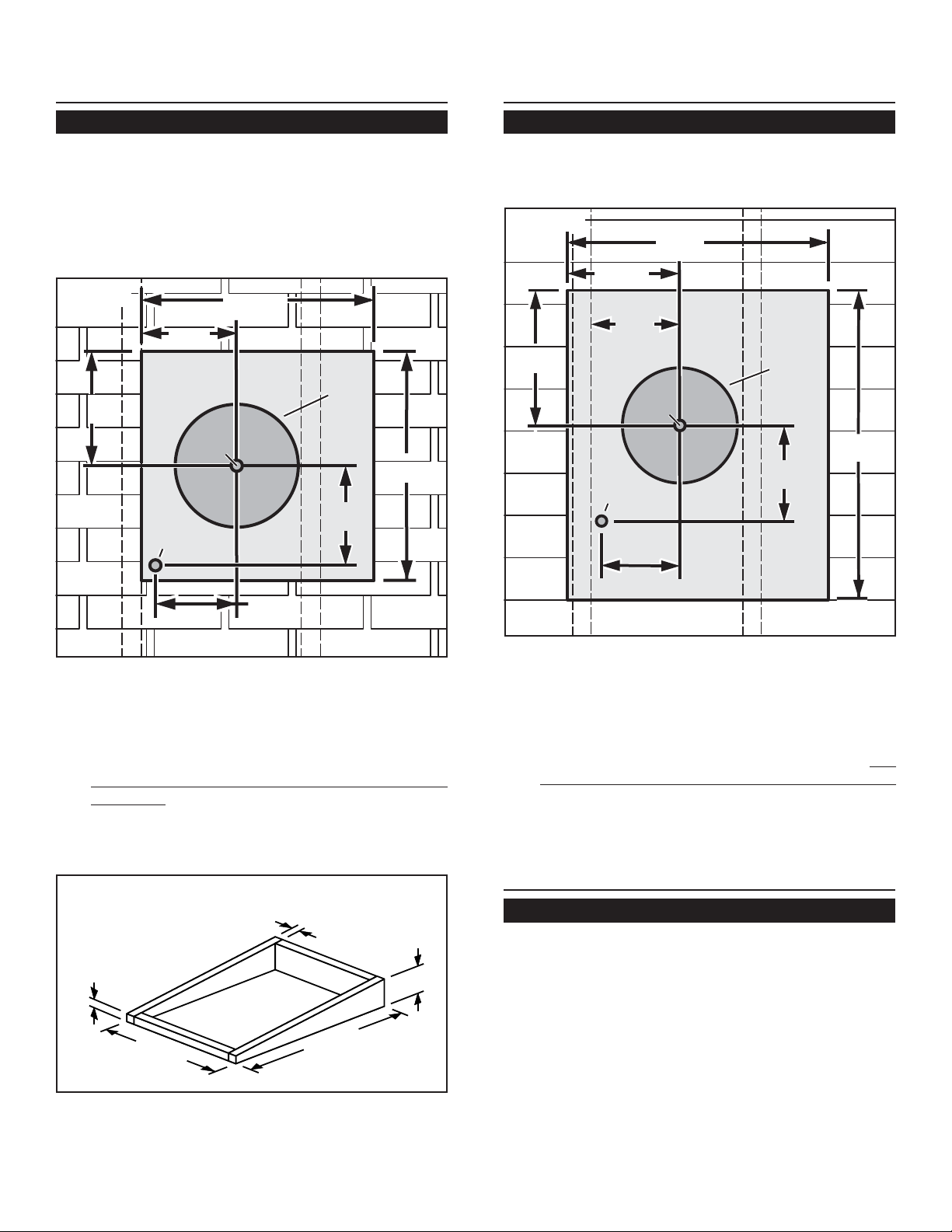
LOCATION
PREPARE THE INSTALLATION
LOCATION
ROOF INSTALLATIONS
1. Locate the blower on the rear slope of the roof.
Place it in a location to minimize duct run. The
location should be free of obstacles (T.V. leads,
electrical lines, etc.). Bear in mind, if the blower top
is level with the roof peak, it will not be seen from
the street. Keep this approximate location in mind
as you work from within the attic.
Figure 1
20¾"
8½"
103/8"
REMOVE
SHINGLES
Pilot
Pilot
Hole
Hole
11"
dia.
hole
20½"
Roof Rafter
1¼"
dia. hole
Roof Rafter
91/8"
WALL INSTALLATIONS
1. Choose a position on the outside wall. Make sure
that no wall studs, pipes or wires run through the
opening area.
Figure 3
24¾"
10¾"
REMOVE
SIDING
11" dia.
hole
127/8"
Wall Stud
8½"
Pilot
Pilot
Hole
Hole
28¼"
1¼"
dia. hole
91/8"
Wall Stud
7¼"
7¼"
OUTSIDE - ROOF VIEW
From inside the attic space:
2. Drill a PILOT HOLE up through the roof, 8½"
from the
inside edge
of a ROOF RAFTER.
From outside - on the roof:
Measure and mark the 20¾" x 20½" rectangle.
3.
Cut and remove only the shingles inside this
rectangle.
Measure and mark the 11" DIAMETER HOLE
4.
and the 1¼" DIAMETER HOLE. Cut these holes
all the way through the roof.
Figure 2
2"
5. For flat roof installations, build a curb that will mount
24¾"
2"
28¼"
the blower at a minimum pitch of 2/12. See Figure
2. Discharge end of the blower should be pointed
away from prevailing winds.
6¾"
OUTSIDE - WALL VIEW
From inside the wall:
2. Drill a PILOT HOLE through the wall, 8½" from
the
inside edge
of a WALL STUD.
From outside - on the wall:
3. Measure and mark the 25" x 29½" rectangle.
and remove only the siding inside this rectangle.
4. Measure and mark the 11" DIAMETER HOLE
and the 1¼" DIAMETER HOLE. Cut these holes
all the way through the wall.
PREPARE THE BLOWER
ALL INSTALLATIONS
1. Unpack the blower assembly.
2. Remove the cover and screws.
3. Remove and discard cardboard from blower wheel.
4. Remove the wiring box cover and screws.
5. Attach an appropriate U.L. approved cable con-
nector in the hole at the rear of the wiring box.
2
Cut
Page 3
INSTALL THE BLOWER
INSTALL THE BLOWER
ROOF INSTALLATIONS
1. Remove roofing nails from the upper 2/3 of the
shingles around the cutout area and carefully lift the
shingles to allow the back flashing sheet on the
blower housing to fit under them.
2. Center the blower ring in the 11" diameter hole,
making sure that the 1-1/4" diameter electrical wiring hole aligns with the hole in the wiring box.
3. Attach the blower to the roof with the six screws
provided. All six holes in the back panel must be
filled, or any moisture that may get inside the blower
housing could leak into the house.
4. Using a good grade of roofing cement, seal all of the
shingles around the housing and flashing sheet as
well as the mounting screw heads.
5. Bring electrical wiring through the hole in the wiring
box and secure it according to local codes.
Figure 4
WALL INSTALLATIONS
1. Place a large bead of caulk on the back side of the
housing along the outer edge.
2. Center the blower ring in the 11" diameter hole,
making sure that the 1-1/4" diameter electrical
wiring hole aligns with the hole in the wiring box.
3. Attach blower to the wall with the six screws
provided. All six holes in the back panel must be
filled, or any moisture that may get inside the
blower housing could leak into the house.
4. Using a good grade of caulk, seal all around the
mounting screw heads.
5. Bring electrical wiring through the hole in the wiring
box and secure it according to local codes.
6. Make the electrical connections with the proper
connector for the type of wire being used. Connect
white to white, black to black, and green or bare
wire to green. See Figure 4.
BLACK
TO
BLACK
120 VAC
LINE IN
WHITE
TO
WHITE
GREEN
TO
GREEN
6. Make the electrical connections with the proper
connector for the type of wiring being used. Connect white to white, black to black, and the green or
bare wire to green. See Figure 4.
7. Replace wiring box cover and screws. Do not pinch
wiring under the cover.
7. Replace wiring box cover and screws. Do not
pinch wiring under cover.
8. Check for free movement of the damper before
installing housing cover and screws.
9. Top and side flanges of the back plate may be
covered with trim strips. Do not block grille opening
at bottom with trim. It will adversely affect performance of the blower.
8. Check for free movement of the damper before
installing housing cover and screws.
3
Page 4

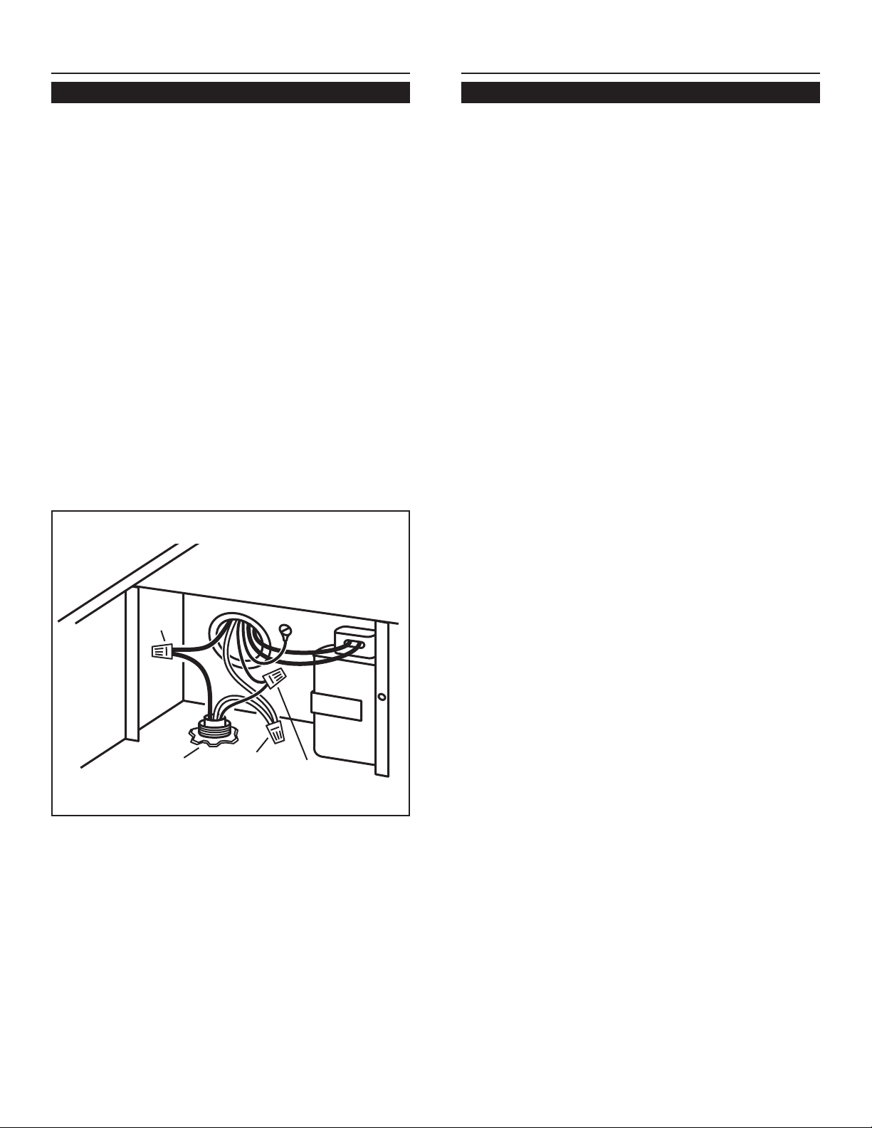
INSTALL THE ROUGH-IN PLATE
USE AND CARE
1. Run 10" round steel ductwork, from exterior blower
to the installation location. For best performance,
use the straightest possible duct run and the fewest number of elbows. Tape all joints.
2. Run 120 VAC electrical power cable from service
panel and from remote blower to installation location.
3. Remove wiring box cover. Remove knockouts
from the wiring box. Feed 6" of power cable through
openings and attach cables to wiring box with
appropriate connectors.
EXTERIOR
BLOWER
ROUGH-IN PLATE LEAD
GREEN
WHITE
BLACK
WIRING BOX
GREEN
BLACK
WHITE
GREEN
WHITE
BLACK
BLACK
WHITE
GREEN
ROUGH-IN PLATE LEAD
LINE IN
120 VAC
60 HZ
10 A MAX.
4. Wire black to black, white to white, and green or
bare wire beneath green ground screw. Replace
wiring box cover.
5. Attach rough-in plate to the studs at the inside top
of hood with (4) #10-24 nuts provided.
6. Connect ductwork to rough-in plate and tape joint.
Disconnect electrical power supply and lock out
service panel before cleaning or servicing this unit.
CLEANING
Remove cover and carefully vacuum blower and
inside of housing. Be careful not to bend or otherwise
damage blower wheel.
MOTOR LUBRICATION
The motor is permanently lubricated. Do not oil or
disassemble motor.
10" DAMPER
MOUNTS INSIDE
DUCTWORK AT
LEAST 3" ABOVE
CANOPY OUTLET
10" ROUND
DUCT
HOUSE
WIRING
WIRE
POWER
CABLE
BOX
COVER
7. Turn on power and check blower operation.
VIKING RANGE CORPORATION
GREENWOOD, MISSISSIPPI 38930 USA
4
99043131E
Page 5

VIKING MODÈLE VEV900
VENTILATEUR MONTÉ À L’EXTÉRIEUR
POUR UTILISATION AVEC LES HOTTES DE CUISINE VIKING VWH, VIH, VBCV, VICV ET DTWN,
24" À 42" (76,2 CM À 106,7 CM) DE LARGEUR, 18" (45,7 CM) DE HAUTEUR.
VEUILLEZ LIRE CES DIRECTIVES ET LES CONSERVER
t damage electrical wiring or other hidden
AVERTISSEMENT
OBSERVEZ LES DIRECTIVES CI-DESSOUS DE
MANIÈRE À RÉDUIRE LES RISQUES D’INCENDIE, DE
CHOC ÉLECTRIQUE OU DE BLESSURES
CORPORELLES.
1. N’utilisez cet appareil que de la manière prévue par le
fabricant. Si vous avez des questions, contactez le
fabricant ou le distributeur.
2. Avant de procéder à la réparation ou à l’entretien de
l’appareil, coupez l’alimentation du panneau d’entrée
d’électricité et verrouillez le dispositif de sectionnement
de manière à empêcher que le courant ne soit
accidentellement rétabli. S’il est impossible de verrouiller
le dispositif de sectionnement, fixez solidement un
écriteau ou une étiquette au panneau d’entrée d’électricité.
3. La pose de l’appareil et les travaux d’électricité doivent
être effectués par des personnes qualifiées en respectant
la réglementation en vigueur, notamment les codes et
normes de la construction ayant trait à la résistance au
feu.
4. Pour éviter les refoulements, l’apport d’air doit être
suffisant de manière à brûler et à évacuer, par le conduit
de fumée (cheminée), les gaz produits par les appareils
à combustibles. Respectez les directives du fabricant de
l’appareil de chauffage et les normes de sécurité,
notamment celles publiées par la National Fire Protection
Association (NFPA), l’American Society for Heating, la
Refrigeration and Air Conditioning Engineers (ASHRAE)
et les codes des autorités locales.
5. When cutting or
AVERTISSEMENT
utilities.
5. Veillez à ne pas endommager le câblage électrique ou
d’autres équipements non apparents lors de la découpe
ou du perçage du mur ou du plafond.
6. Les ventilateurs canalisés doivent toujours être ventilés
à l’air libre.
7. Pour réduire les risques d’incendie, utilisez seulement
des conduits en métal.
8. Cet appareil doit être mis à la terre.
ATTENTION
1. Cet appareil ne doit servir qu’à la ventilation générale. Ne
l’utilisez pas pour éliminer des matières ni des vapeurs
dangereuses ou explosives.
2. Pour éviter d’endommager les roulements du moteur, de
déséquilibrer les pales ou de les rendre bruyantes,
débarrassez l’appareil de la poussière de plâtre, de
construction, etc.
3. Veuillez lire l’étiquette de spécifications du produit pour
obtenir plus de renseignements, notamment sur les
normes.
4. Le circuit électrique, y compris la commande de régime
(le cas échéant), doit avoir au minimum une puissance
nominale de 6 ampères.
Dimensions de ventilateur
71,8 cm (28.25") x 62,9 cm (24.75") x 18,2 cm (7.17")
SPÉCIFICATIONS
MODÈLE VOLTS AMPÈRES PCM DU CONDUIT
VEV900 120 5,7 900 DIAMÈTRE
DIMENSION
DE 25,4 cm
(10 po)
PLANIFICATION DE LA POSE
TOUS LES TYPES DE POSE
1. L’emplacement du ventilateur doit être choisi de manière
à réduire le plus possible l’utilisation de conduits et de
coudes.
2. Lorsque cela est envisageable, le ventilateur doit être
centré entre les poteaux muraux ou les chevrons du toit.
3. Évitez les tuyaux, les fils ou autres conduits qui peuvent
passer dans les murs.
INSTALLATEUR : Veuillez laisser ce manuel au propriétaire
PROPRIÉTAIRE : La page 8 contient des renseignements portant sur l’utilisation et l’entretien
5
Page 6

PRÉPARATION DE
20½"
11"
dia.
hole
103/
8"
1¼"
dia. hole
8½"
20¾"
7¼"
91/
8"
REMOVE
SHINGLES
Pilot
Hole
OUTSIDE - ROOF VIEW
11" dia.
hole
29½"
1¼"
dia. hole
127/8"
10¾"
25"
7¼"
91/8"
Wa l l S t u d
Wa l l S t u d
REMOVE
SIDING
8½"
Pilot
Hole
OUTSIDE - WALL VIEW
L’EMPLACEMENT
POSES SUR LES TOITS
1. Choisissez un emplacement pour le ventilateur sur la
pente arrière du toit. Placez-le de sorte à réduire au
maximum l’utilisation de conduits. Cet emplacement
doit être exempt d’obstacles (fils de téléviseur, lignes
électriques, etc.). Rappelez-vous que si le dessus du
ventilateur est à la même hauteur que le faîte du toit, il
ne pourra être aperçu de la rue. Gardez cet emplacement
en tête pendant que vous travaillez à partir du grenier.
Figure 1
264 mm
103/
8"
(10 3/8 po)
216 mm
8½"
(8 ½ po)
ENLEVEZ
REMOVE
LES
BARDEAUX
SHINGLES
Chevron
Orifice d’un
Roof Rafter
diamètre de
32 mm
1¼"
(1 ¼ po)
dia. hole
Avant-
Pilot
Pilot
trou
Hole
Hole
527 mm
20¾"
(20 ¾ po)
Orifice d’un
11"
diamètre de
279 mm (11 po)
dia.
hole
Chevron
232 mm
Roof Rafter
(9 1/
91/
8"
8 po)
521 mm
(20 1/2 po)
20½"
PRÉPARATION DE
L’EMPLACEMENT
POSES SUR LES MURS
1. Choisissez un emplacement sur le mur extérieur.
Assurez-vous qu’aucun poteau mural, tuyau ou câble ne
passe au niveau de l’ouverture.
Figure 3
327 mm
127/8"
(12-7/8 po)
628.7 mm (24¾ po)
273 mm
10¾"
(10¾ po)
216 mm
8½"
(8½ po)
Wall Stud
Poteau mural
Orifice d’un
diamètre de
1¼"
32 mm
dia. hole
(1¼ po)
Pilot
Pilot
Avant-
trou
Hole
Hole
25"
ENLEVEZ
REMOVE
SIDING
PAREMENT
184 mm
7¼"
(7¼po)
LE
Orifice
d’un
11" dia.
diamètre
de
hole
279 mm
(11 po)
232 mm
91/8"
(9-1/8 po)
Wall Stud
Poteau mural
717.6 mm
29½"
(28¼ po)
184 mm
7¼"
(7 ¼ po)
OUTSIDE - ROOF VIEW
EXTÉRIEUR – VUE DU TOIT
De l’intérieur du grenier
2. Percez un AVANT-TROU à travers le toit, à une distance
de 216 mm (8 ½ po) du
rebord intérieur
d’un CHEVRON.
De l’extérieur –sur le toit :
3. Mesurez et tracez un rectangle de 527 mm x 521 mm
(20 ¾ po x 20 ½ po). Coupez et retirez seulement les
bardeaux qui se trouvent à l’intérieur de ce rectangle.
4. Mesurez et tracez un ORIFICE D’UN DIAMÈTRE DE
279 MM (11 PO) et un ORIFICE D’UN DIAMÈTRE DE
32 MM (1 ¼ PO). Découpez ces orifices de part en
part du toit.
Figure 2
51 mm
(2 po)
2"
5. Pour la pose sur un toit plat, construisez un cadre porteur
pour supporter le ventilateur en vous assurant que la pente
628.7 mm
24¾"
(24¾ po)
51 mm
(2 po)
2"
28¼"
717.6 mm
(28¼ po)
171.5 mm
(6¾ po)
6¾"
minimale est de 2/12. Reportez à la figure 2. L’extrémité du
conduit d’évacuation du ventilateur ne doit pas être orientée
dans la direction des vents dominants.
OUTSIDE - WALL VIEW
EXTÉRIEUR –VUE DU MUR
De l’intérieur du mur :
2. Percez un AVANT-TROU à travers le mur, à une
distance de 216 mm (8 ½ po) du
rebord intérieur
POTEAU MURAL.TUD.
De l’extérieur –sur le mur :
3. Mesurez et tracez un rectangle de 635 mm x 749 mm
(25 po x 29,5 po). Coupez et retirez seulement les
bardeaux qui se trouvent à l’intérieur de ce rectangle.
4. Mesurez et tracez un ORIFICE D’UN DIAMÈTRE DE
279 MM (11 PO) et un ORIFICE D’UN DIAMÈTRE
DE 32 MM (1 ¼ PO). Découpez ces orifices de part
en part du mur.
PRÉPARATION DU VENTILATEUR
TOUS LES TYPES DE POSE
1. Déballez le ventilateur.
2. Retirez le couvercle et les vis.
3. Enlevez l’emballage de carton protégeant la roue du
ventilateur puis jetez-le.
4. Retirez le couvercle du boîtier de câblage et les vis.
5. Fixez un connecteur de câble homologué U.L. dans
l’ouverture à l’arrière du boîtier de câblage.
6
d’un
Page 7

POSE DU VENTILATEUR
POSE DU VENTILATEUR
POSES SUR LES TOITS
1. Retirez les deux premiers tiers des clous à toiture des
bardeaux se trouvant autour de la surface de découpe
puis soulevez délicatement les bardeaux de manière à
permettre à la tôle de rejéteau de s’y glisser.
2. Centrez l’anneau de ventilateur dans le trou de 27,9 cm
(11 po) de diamètre, en s’assurant que l’orifice pour le
câblage électrique de 3,2 cm de diamètre (1 1/4 po)
coïncide avec l’orifice dans le boîtier de câblage.
3. Fixez le ventilateur au toit à l’aide des six vis fournies.
Tous les six trous du panneau arrière doivent être couverts,
sans quoi de l’humidité peut pénétrer à l’intérieur du
ventilateur et couler dans l’habitation.
4. Imperméabilisez tous les bardeaux autour du boîtier et de
la feuille de tôle ainsi que les têtes des vis de montage à
l’aide d’un enduit à toiture de bonne qualité.
5. Faites passer le câblage électrique par l’ouverture du
boîtier de câblage et fixez-le en respectant la
réglementation locale.
Figure 4
POSES SUR LES MURS
1. Appliquez une large bande de produit à calfeutrer à
l’arrière du boîtier, le long du rebord extérieur.
2. Centrez l’anneau de ventilateur dans le trou de 27,9 cm
(11 po) de diamètre, en s’assurant que l’orifice pour le
câblage électrique de 3,2 cm de diamètre (1 1/4 po)
coïncide avec l’orifice dans le boîtier de câblage.
3. Fixez le ventilateur au mur à l’aide des six vis fournies.
Tous les six trous du panneau arrière doivent être
couverts, sans quoi de l’humidité peut pénétrer à l’intérieur
du ventilateur et couler dans l’habitation.
4. Imperméabilisez le pourtour des têtes de vis de montage
à l’aide d’un produit à calfeutrer de bonne qualité.
5. Faites passer le câblage électrique par l’ouverture du
boîtier de câblage et fixez-le en respectant la
réglementation locale.
6. Effectuez les branchements électriques en utilisant le
connecteur convenant au type de câblage utilisé. Branchez
les fils noirs ensemble, les fils blancs ensemble et le fil
vert ou le fil dénudé avec le fil vert. Reportez-vous à la
Figure 4.
BLACK
NOIR
TO
AU
BLACK
NOIR
CÂBLE
120 VAC
ÉLECTRIQUE
LINE IN
120 VAC
WHITE
BLANC
TO
AU
WHITE
BLANC
GREEN
VERT
TO
AU
GREEN
VERT
6. Effectuez les branchements électriques en utilisant le
connecteur convenant au type de câblage utilisé. Branchez
les fils noirs ensemble, les fils blancs ensemble, et le fil
vert ou le fil dénudé avec le fil vert. Reportez-vous à la
Figure 4.
7. Replacez le couvercle du boîtier de câblage et les vis. Ne
pincez pas le câblage sous le couvercle.
7. Replacez le couvercle du boîtier de câblage et les vis. Ne
pincez pas le câblage sous le couvercle.
8. Assurez-vous que le clapet peut bouger librement avant
d’installer le couvercle du boîtier et les vis.
9. Les rebords supérieurs et latéraux de la plaque arrière
doivent être recouverts avec des tringles de finissage.
Ne bloquez pas la partie inférieure de la grille à air avec
les tringles. Le rendement du ventilateur en serait
affecté.
8. Assurez-vous que le clapet peut bouger librement avant
d’installer le couvercle du boîtier et les vis.
7
Page 8

POSE DE LA PLAQUE DE RACCORDEMENT
UTILISATION ET ENTRETIEN
1. Faites cheminer les conduits ronds en acier de 25,4 cm
(10 po) du ventilateur extérieur vers la hotte. Pour un
meilleur rendement, utilisez le conduit rond le plus droit
possible et réduisez au maximum l’utilisation de coudes.
Scellez tous les joints avec du ruban adhésif.
2. Faites cheminer le câble électrique de 120 V.C.A. du
panneau d’entrée d’électricité et du ventilateur vers la
hotte.
3. Retirez le couvercle du boîtier de câblage. Retirez les
entrées sectionnables de la boîte de câblage. Faites
passer 15,2 cm (6 po) de câble électrique par les
ouvertures et fixez les câbles du boîtier de câblage aux
connecteurs appropriés.
WIRING BOX
EXTERIOR
VENTILATEUR
BLOWER
EXTÉRIEUR
CÂBLAGE DE PLAQUE
DU VENTILATEUR
VERT
GREEN
BLANC
WHITE
BLACK
NOIR
NOIR
BLACK
WHITE
ROUGH-IN PLATE LEAD
BLANC
BOîTIER DE CÂBLAGE
VERT
GREEN
GREEN
VERT
WHITE
BLANC
BLACK
NOIR
BLACK
NOIR
BLANC
WHITE
VERT
GREEN
CÂBLE
LINE IN
ÉLECTRIQUE
120 VAC
120 VAC
60 HZ
60 HZ
10 A MAX.
10 A MAX.
CÂBLAGE DE PLAQUE
ROUGH-IN PLATE LEAD
DU VENTILATEUR
4. Branchez les fils noirs ensemble, les fils blancs ensemble
puis placez le fil vert ou le fil dénudé sous la vis de borne
de terre verte. Replacez le couvercle du boîtier de
câblage.
5. Fixez la plaque du ventilateur aux goujons se trouvant sur
la partie supérieure de l’intérieur de la hotte à l’aide de (4)
écrous n
o
10-24, inclus.
6. Branchez le conduit à la plaque de raccordement et
scellez le joint avec du ruban adhésif.
Débranchez l’alimentation électrique et verrouillez le panneau
d’entrée d’électricité avant de nettoyer ou de réparer l’appareil.
NETTOYAGE
Retirez le couvercle et passez soigneusement l’aspirateur
à l’intérieur du boîtier. Veillez à ne pas courber ou endommager
la roue du ventilateur.
LUBRIFICATION DU MOTEUR
Le moteur est lubrifié en permanence. Il ne doit pas être
huilé ni démonté.
AMORTISSEUR DE
10 po BÂTIS À
L'INTERIEUR DE
CONDUIT A MOINS
3 po AU-DESSUS DE
SORTIE DE VERRIÈRE
CONDUIT ROND DE
15,2 CM (10 PO)
CÂBLAGE
DOMESTIQUE
COUVERCLE
CÂBLE D’ALIMENTATION
DU BOÎTIER
DE CÂBLAGE
7. Mettez l’appareil sous tension et vérifiez le fonctionnement
du ventilateur.
VIKING RANGE CORPORATION
GREENWOOD, MISSISSIPPI 38930 USA
8
99043131E
 Loading...