

Page 1
Service
Manual
This manual is to be used by qualied appliance technicians only. Viking
does not assume any responsibility for property damage or personal
injury for improper service procedures done by an unqualied person.
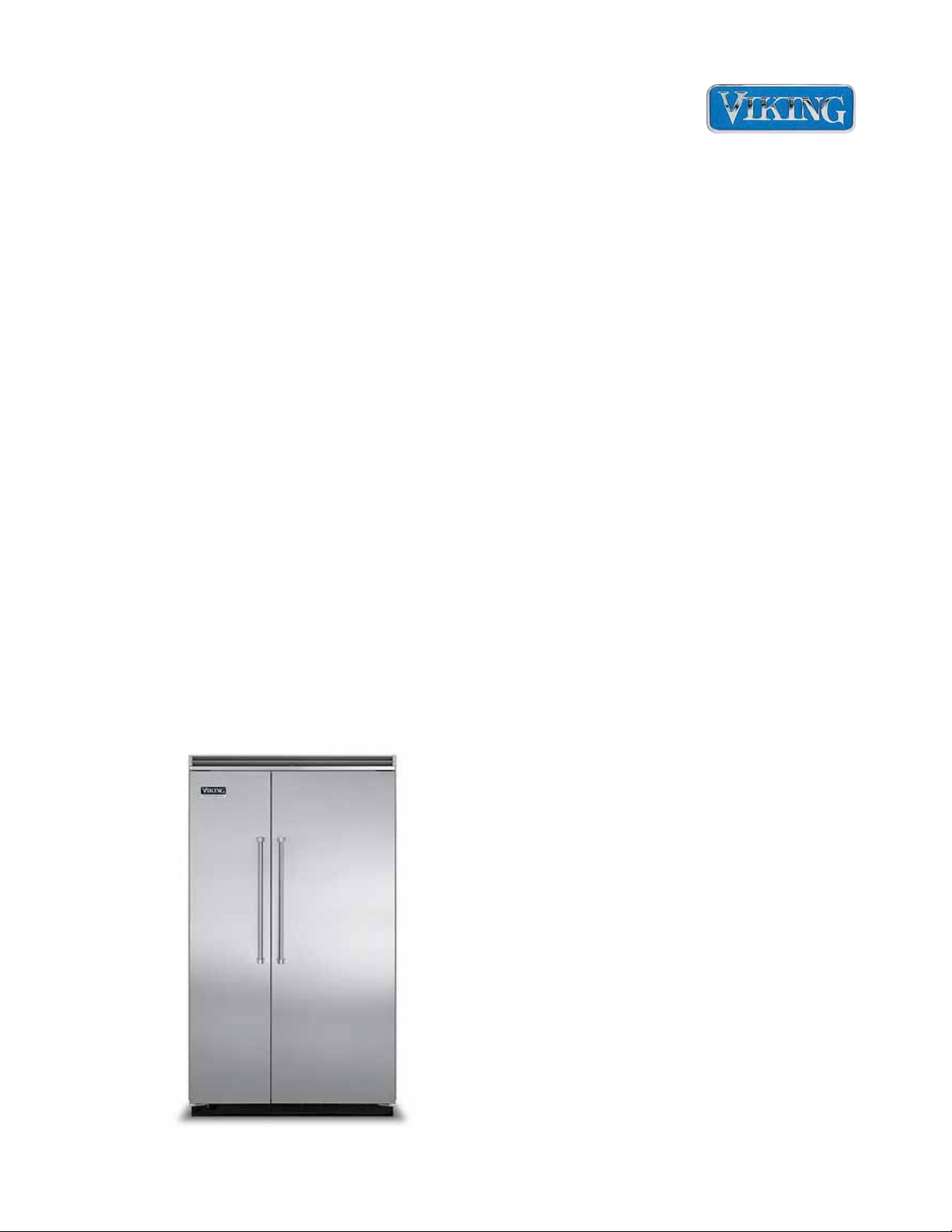
Built-In
Side by Side
Non-Dispenser
®
Preferred Service
This Base Manual covers general and
specic information including, but not
limited to the following models:
Refrigerator /
Freezer
FDSB5421
FDSB5481
VCSB5421
VCSB5481
SMR-0020
MAY 2012
Page 2
Table of Contents
Important Information 3
Safety Information .................................................... 3
Warnings .................................................................. 4
Electrical Requirements ........................................ 4
Tip Over Hazard .................................................... 4
General Information 5
Model - Serial Number Matrix .................................. 5
Operation 6
Settings and Functions ............................................ 6
Electronic Temperature Settings ........................... 6
Electronic Temperature Settings ........................... 6
Key Press Conrmation ........................................ 6
Fast Cool .............................................................. 7
MAX FRZ .............................................................. 7
MAX REF .............................................................. 7
Forced Pull-Down (Forced compressor start) ....... 8
Forced Defrost ...................................................... 8
Showroom Mode .................................................. 9
Sabbath Mode ...................................................... 9
Fahrenheit to Celsius ............................................... 9
Display Panel Operation ........................................ 10
Temperature Control Operation .............................11
Disassembly 12
Parts Location–Control Panel ................................ 12
Upper Grille Assembly ........................................ 13
Control Panel ..................................................... 13
Control Panel (continued) .................................. 14
Overlay Switch .................................................... 14
Overlay Switch (continued) ................................. 15
High Voltage Board ............................................ 15
Low Voltage Board ............................................. 15
Power Disconnect Switch ................................... 16
Inverter ................................................................ 16
Inverter (continued) ............................................ 17
Condenser Fan ................................................... 17
Parts Location–Refrigerator Compartment ............ 18
Light Assembly .................................................... 19
Fresh Food Fan Assembly .................................. 19
Interior Lights ...................................................... 20
Plasma Cluster™ ................................................ 20
Parts Location–Freezer Compartment and Lower
Unit–Non Dispenser ............................................... 21
Ice Maker (shown here with cover off) ................ 22
Thermal Cut Out (TCO) ...................................... 25
Freezer Evaporator Fan ..................................... 25
Freezer Thermistor ............................................. 26
Defrost Heater ................................................... 26
Defrost Terminator ............................................. 28
Float Switch ........................................................ 28
Water Valve ......................................................... 29
Drain Pan Heater ................................................ 29
Service Procedures 30
Program Modes ..................................................... 30
2 ©2012 Viking Preferred Service
Program Mode A .................................................... 30
Display Ref Temperature .................................... 30
Display Frz Temperature ..................................... 30
Defrost mode selection ....................................... 30
Conventional defrost time adjustment (CRTD) ... 30
Compressor low speed frequency ...................... 31
Adjust Cut-In Hysteresis .................................... 31
Adjust Cut-Out Hysteresis .................................. 32
Display Software Version .................................... 33
Exiting Mode A .................................................... 33
Program Mode B .................................................... 34
Adjust Freezer Temperature Offset ..................... 34
Adjust Refrigerator Temperature Offset .............. 34
Adjust MAX FRZ duration ................................... 35
Adjust MAX REF duration ................................... 35
Adjust FAST COOL duration ............................... 35
Adjust Door Open Alarm delay ........................... 36
Adjust Compressor Dwell Time ........................... 36
Adjust Compressor High Frequency ................... 36
Adjust DC Fan Cycling On Time ......................... 36
Adjust DC Fan Cycling Off Time ......................... 36
Exiting Mode B .................................................... 36
Program Mode C .................................................... 37
Set Model type .................................................... 37
Adjust Freezer Upper Temperature Limit ............ 37
Adjust Freezer Lower Temperature Limit ............ 37
Adjust Refrigerator Upper Temperature Limit ..... 38
Adjust Refrigerator Lower Temperature Limit ..... 38
Defrost lockout adder .......................................... 38
Defrost start delay ............................................... 39
Defrost termination delay .................................... 39
Constant Evaporator fan mode ........................... 39
Plant mode .......................................................... 39
ALARMS ................................................................ 40
1. High Temp Alarm ............................................ 40
2. Open Thermistor Alarm ................................... 40
3. Shorted Thermistor Alarm ............................... 41
4. Power Loss Alarm ........................................... 41
5. Door Open Alarm ............................................ 41
TABLE 1 - Model types ......................................... 42
Door Stop Adjustment ............................................ 43
Light Bulb ............................................................... 43
Door Hinge Adjustment .......................................... 43
Height Adjustment .................................................. 44
Diagnostics 46
VCC3 Inverter Diagnostic Codes ........................... 46
High Voltage Board ................................................ 47
Low Voltage Board ................................................. 48
Troubleshooting Guide ........................................... 49
Wiring Diagrams 52
Wiring and Component Testing .............................. 52
High Voltage Board ................................................ 52
Side by Side schematic .......................................... 53
Side by Side Wiring Diagram ................................. 54
Page 3
Important Information
SAVE THESE INSTRUCTIONS
REVIEW ALL SERVICE INFORMATION IN THE APPROPRIATE SERVICE MANUAL AND TECHNICAL SHEETS
BEFORE BEGINNING REPAIRS.
Pride and workmanship go into every product to provide our customers with quality products. It
is possible, however, that during its lifetime, a product may require service. Products should be
serviced only by a qualified service technician that is familiar with the safety procedures required
in the repair and who is equipped with the proper tools, parts, testing instruments, and the
appropriate service manual.
Safety Information
We have provided many important safety
messages in this manual and on the appliance.
Always read and obey all safety messages.
This is the safety alert symbol.
To avoid risk of serious injury or death, repairs should
not be attempted by unauthorized personnel.
WARNING!
!
This symbol alerts you to hazards that can kill
or hurt you and others. All safety messages will
be preceded by the safety alert symbol and the
word “DANGER”, “WARNING”, or “CAUTION”.
These words mean:
DANGER!
IMMEDIATE HAZARDS WHICH WILL RESULT IN
SEVERE PERSONAL INJURY OR DEATH.
WARNING!
Hazards or unsafe practices which COULD result in
severe personal injury or death.
CAUTION!
CAUTION!
VIKING will not be responsible for any injury or
property damage from improper service procedures.
If performing service on your own product, you must
assume responsibility for any personal injury or
property damage which may result.
Technical support for authorized servicers:
1-800-914-4799
Address your written correspondence to:
Viking Preferred Service
1803 HWY 82 West
Greenwood, MS 38930
Hazards or unsafe practices which COULD result in
minor personal injury or product or property damage.
All safety messages will identify the hazard, tell
you how to reduce the chance of injury, and tell
you what can happen if the instructions are not
followed.
©2012 Viking Preferred Service 3
Page 4
Important Information
Warnings
Read and follow all instructions before using
this appliance to prevent the potential risk of
re, electric shock, personal injury, or damage
to the appliance as a result of improper usage
of the appliance. Use appliance only for its
intended purpose as described in this manual.
To ensure proper and safe operation: appliance
must be properly installed and grounded by a
qualied technician. DO NOT attempt to adjust,
repair, service, or replace any part of your
appliance unless it is specically recommended
in this manual. All other servicing should be
referred to a qualied servicer.
Make sure that incoming voltage is the same
as unit rating. An electric rating plate specifying
voltage, frequency, wattage, amperage, and
phase is attached to the product.
Electrical Requirements
WARNING!
TIP OVER HAZARD
Appliance is top heavy and tips easily when not
completely installed. Keep doors closed until
appliance is completely installed and secured per
installation instructions.Use two or more people to
move and install appliance. Failure to do so can
result in death or serious injury.
WARNING!
ELECTRICAL SHOCK HAZARD
Disconnect power or turn power disconnect switch
to “OFF” position before removing top grille. Failure
to do so can result in death or electrical shock.
WARNING!
Assure that the electrical installation is
adequate and in conformance with the National
Electrical Code, ANSI/NFPA 70-latest edition
or Canadian Electrical Code C22.1-1998 and
C22.2 No. 0-M91 (or latest edition), and all
local codes and ordinances. A 115 volt, 60-Hz,
15 amp, fused, electrical supply is required. It
is required that
a separate circuit serving only this appliance
be provided. This appliance is equipped with a
power supply cord having a 3-prong grounding
plug.
To minimize possible shock hazard, the cord
must be plugged into a mating 3-prong,
grounding-type wall receptacle. DO NOT use
an extension cord.
Tip Over Hazard
Most of the unit’s weight is at the top. Extra
care is needed when moving the unit to prevent
tipping. Keep doors closed until appliance is
completely installed and secured per installation
instructions. Use two or more people to move
and install appliance. Failure to do so can result
in death or serious injury.
ELECTRICAL SHOCK HAZARD
Plug into a grounded 3-prong outlet. If a
2-prong wall receptacle is encountered, contact a
qualied electrician.
DO NOT remove ground prong. Unit must be
grounded at all times. DO NOT use an adapter.
DO NOT use an extension cord.
Failure to follow these instructions can result in
death, re, or electrical shock.
WARNING!
BURN HAZARD
DO NOT touch condenser coils near defrost pan.
Doing so can result in burns.
4 ©2012 Viking Preferred Service
Page 5
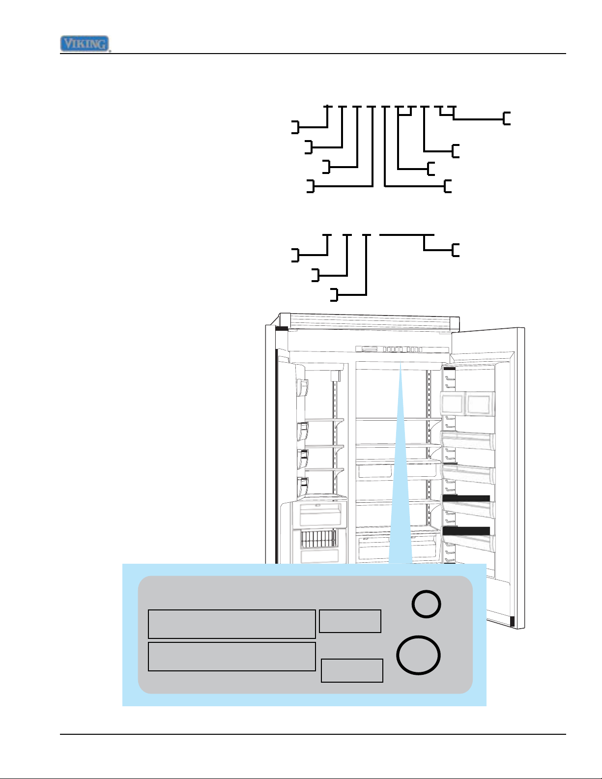
Model - Serial Number Matrix
VIKING RANGE CORP. LISTED HOUSEHOLD
General Information
V C S B 5 4 8 1 S S
Model Numbers
Serial Numbers
The serial number and model
number for your appliance are
located on the identication
plate mounted on the upper
left side of the door opening.
Viking Professional Series
Commercial
Side by Side
Built-In
Month
Year of Manufacture
Stainless
Refresh
48" Wide
Version
02 15 12 R1000264
Serial Number
Day
GREENWOOD, MISSISSIPPI 38930 REFRIGERATOR 35NN
MODEL/MODELE FDSB5421SS 6.25OZ R134a
NUMBER/NUMERO
SERIAL/SERIE 021512R10000264 115 VAC/60 HZ
NUMBER/NUMERO
©2012 Viking Preferred Service 5
AMPS: 9.9
PE920095
c
U
U
L
L
Page 6
Operation
Settings and Functions
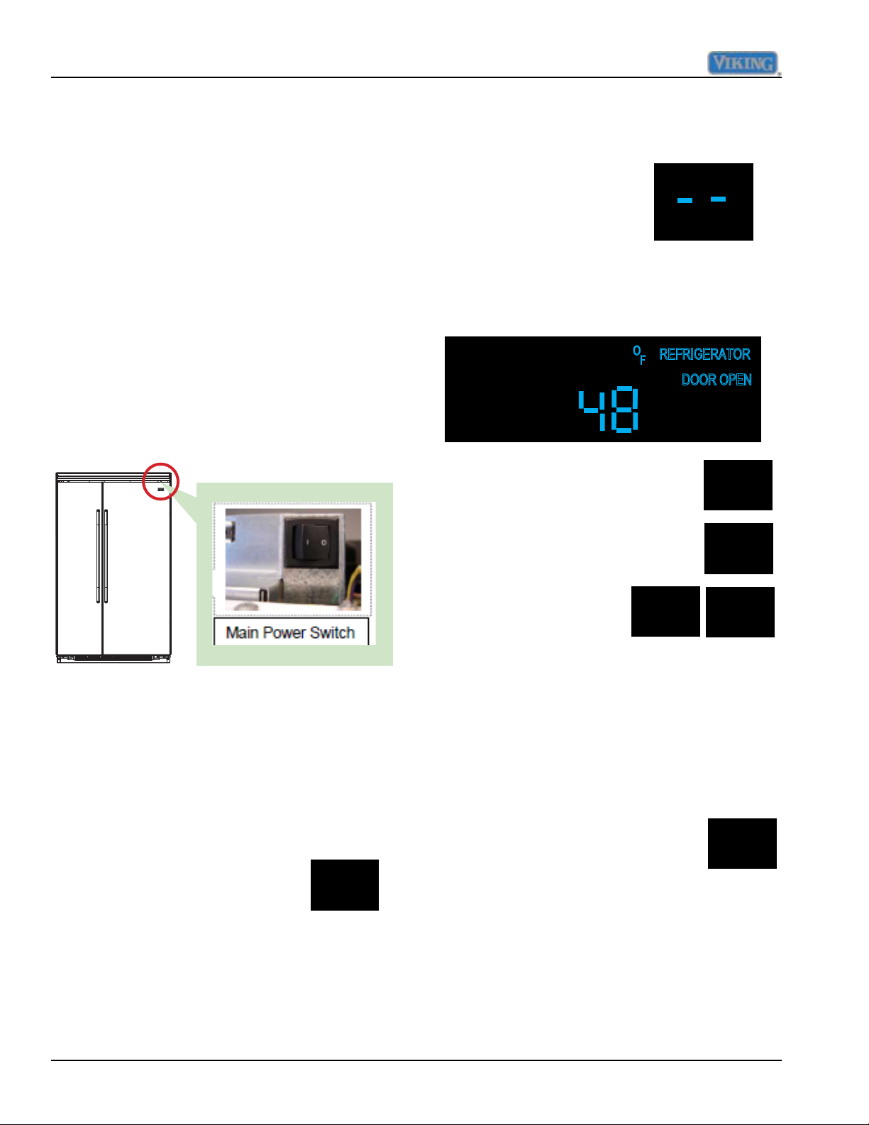
Power On/Off Switch (Power Interruption
Switch) The power on/off switch is located
behind your refrigerator’s top grille. It is used
to turn the power “OFF” when cleaning the
refrigerator or changing the light bulbs. Your
refrigerator arrives from the factory with the
power interruption switch “ON”.
To turn power “OFF”, remove the center grille
blade. Press the power on/off switch to the
“OFF” position.
To turn power “ON”, press power on/off switch
to the “ON” position. Replace the center grille
blade.
Electronic Temperature Settings
When power is first applied to the refrigerator,
there will be two dashes
displayed as in illustration.
After approximately thirty
seconds the digital display
will change to numbers,
indicating temperature in the refrigerator
(default upon initial start-up) compartment
along with the word REFRIGERATOR and
degrees Fahrenheit.
To adjust temperature , enable
the key pad controls by pressing
and releasing the "ACTIVATE
ACTIVATE
CONTROLS
CONTROLS" pad. Select "REF
TEMP" or "FRZ TEMP" pad
for applicable section. The
FRZ
TEMP
temperature is then
adjusted in that section
HIGHER
LOWER
by pressing "HIGHER
or LOWER" pad while
observing digital readout.
IMPORTANT: Be sure the power on/off
switch is in the “ON” position after cleaning or
changing light bulbs.
Key Press Confirmation
The key press confirmation is the "beep" that
is heard when a control pad is pressed. This
audible confirmation can be made active or
Electronic Temperature Settings
Your refrigerator’s electronic controls are
located behind the door above
the cabinet interior. To activate
the electronic control panel,
ACTIVATE
CONTROLS
press “ACTIVATE CONTROLS”
pad. All other pads, except the “Alarm Off”
pad, will remain inactive until the ”ACTIVATE
CONTROLS” pad is pressed. Once activated,
pad remains programmable for at least ten
minutes
6 ©2012 Viking Preferred Service
inactive.
To deactivate the confirmation
ACTIVATE
CONTROLS
beep press and hold "ACTIVATE
CONTROLS" pad for three seconds,
three long beeps will be heard, confirming
deactivation.
To activate the confirmation beep press and
hold "ACTIVATE CONTROLS" pad for three
seconds, three long beeps will be heard,
confirming activation.
Page 7
Operation
Fast Cool
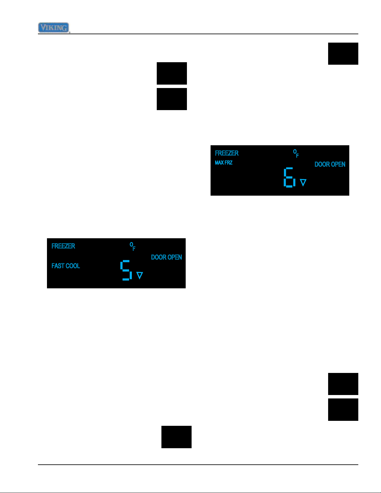
Fast Cool is enabled by pressing
and releasing the "ACTIVATE
ACTIVATE
CONTROLS
CONTROLS" pad and then
pressing and releasing the "FAST
COOL"pad.
FAST
COOL
This causes the control to
temporarily (predetermined time, factory
default is 2 hours) replace the freezer setpoint
o
to Max Frz temperature (factory default -5
F)
and also the refrigerator setpoint to Max Ref
temperature (factory default 33
o
F).
Max Frz time duration is adjustable in
Program Mode B, range is 1 to 20 hours in 1
hour increments.
The only temperature speed used during this
mode of operation is high speed (115HZ).
and releasing the "MAX FRZ" tab.
MAX
FRZ
This causes the control to
temporarily (factory setting is 6
hours) change the current freezer set point
o
F. This set point temperature is not
to -5
adjustable and is programmed from factory.
The time duration is adjustable in Program
Mode B, range is 1 to 20 hours in 1 hour
increments.
When MAX FRZ is selected, the display
illuminates "MAX FRZ" as shown above. The
temperature display will move towards that
set point temperature (- 5
o
F) as the unit pulls
down.
When "FAST COOL" is selected by pressing
the pad, "FAST COOL" is illuminated on the
display as shown in illustration above.
Fast Cool will terminate after the time
duration has expired or if another mode is
selected or if temperature is increased or
decreased by pressing "HIGHER or LOWER"
tabs. Fast Cool can be cancelled by pressing
"FAST COOL" again, the Fast Cool will
extinguish on the display.
MAX FRZ
Max Frz is enabled by pressing
and releasing the "ACTIVATE
ACTIVATE
CONTROLS
CONTROLS" pad and then Pressing
Max Frz will terminate at the conclusion
of the time duration or if another mode is
selected, or if the temperature is manually
changed by pressing "HIGHER or LOWER"
tabs. Max Frz can also be terminated by
again pressing and releasing "MAX FRZ".
The conclusion or termination of this mode is
confirmed by "MAX FRZ" extinguishing from
display.
MAX REF
Max Ref is enabled by pressing
and releasing the "ACTIVATE
ACTIVATE
CONTROLS
CONTROLS" pad and then
Pressing and releasing the "MAX
FRZ" tab.
MAX
REF
This causes the control to
temporarily (factory setting is 4 hours) change
o
the current refrigerator set point to 33
F.
©2012 Viking Preferred Service 7
Page 8

Operation
This set point temperature is not adjustable
and is programmed from factory.
The time duration is adjustable in Program
Mode B, range is 1 to 20 hours in 1 hour
increments.
When MAX REF is selected, the display
illuminates "MAX REF" as shown above. The
temperature display will move towards that
set point temperature (33o F) as the unit pulls
down.
Max Ref will terminate at the conclusion of the
time duration or if another mode is selected,
or if the temperature is manually changed by
pressing "HIGHER or LOWER" tabs. Max Ref
can also be terminated by again pressing and
releasing "MAX REF".
The conclusion or termination of this mode is
confirmed by "MAX REF" extinguishing from
display
Forced Pull-Down (Forced compressor
start)
This function will ignore compressor dwell
time and cause immediate compressor start
up in the high speed mode (115HZ).
Forced pull-down will terminate after both
cut-out temperatures are met, or if a defrost
or forced defrost is initiated, or if an extended
power loss occurs.
Forced Defrost
To enter Forced defrost, first
press and release "ACTIVATE
ACTIVATE
CONTROLS
CONTROLS", then press and hold
"HIGHER" pad, then press and hold
"DISPLAY OFF" pad until you get an
HIGHER
audible consisting of three beeps.
This causes the control to
DISPLAY
OFF
immediately suspend all
temperature control operations
and start a defrost cycle, regardless of
compressor dwell time and defrost start delay.
If defrost terminator temperature is satisfied
defrost heaters will come on at this time for a
normal defrost cycle.
Forced defrost will terminate when defrost
terminator opens (completion of cycle defrost)
or if forced pull-down is initiated or if there is a
long power loss..
To enter Forced pull-down, first
press and release "ACTIVATE
ACTIVATE
CONTROLS
CONTROLS", then press and hold
"LOWER" pad, then press and hold
"DISPLAY OFF" pad also until you
LOWER
get an audible consisting of three
beeps.
This causes the control to
immediately energize the
appropriate outputs in an effort to reach both
of the cut-out temperatures (refrigerator and
freezer).
8 ©2012 Viking Preferred Service
DISPLAY
OFF
When forced defrost is initiated the
temperature numbers are replaced with
"dEF" in the seven segment displays, as
shown above. When defrost is complete the
displayed "dEF" will again be replaced with
displayed temperature numerals.
Page 9
Showroom Mode
Showroom mode allows electronic controls and
interior lights to function independently of the
refrigeration system.
Operation
ACTIVATE
CONTROLS
To enter Showroom mode:
Press and hold the “ACTIVATE
CONTROLS” pad. While holding,
press and hold the “HIGHER” and
“ALARM OFF” pad simultaneously.
HIGHER
Continue holding until three beeps
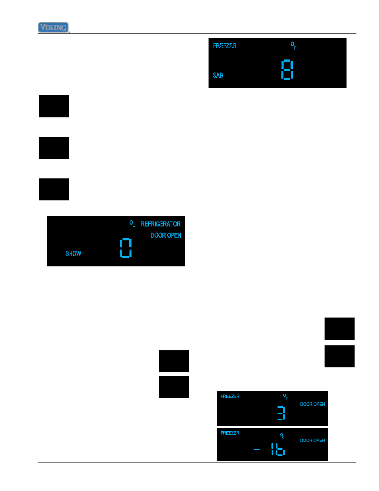
are heard and then "SHOW" is
illuminated along with Refrigerator
and 38OF or Freezer and 0OF.
Whichever section was active
ALARM
OFF
prior to to showroom mode being
entered will determine which one is
displayed.
To exit Showroom mode: Press and hold the
“ACTIVATE CONTROLS” pad. While holding,
press and hold the “HIGHER” and “ALARM
OFF” pad simultaneously. Continue holding
until three beeps are heard. The display will
revert to normal operation
HIGHER
Sabbath Mode
To enter Sabbath mode, press and
hold "ACTIVATE CONTROLS" pad
ACTIVATE
CONTROLS
then press and hold "DISPLAY
OFF" pad, together for three
seconds this will cause an audible
DISPLAY
OFF
three beeps, signifying that
Sabbath mode has been entered.
When Sabbath mode has been entered the
display goes blank except for the "SAB",
see illustration below, which will remain
illuminated whether the door(s) are open or
closed, it will not change state.
Sabbath mode is used to control the
refrigerator without interior lights, LED
display changes and enunciators. Alarms are
suppressed, you will not get visual or audible
alarms during Sabbath mode, although they
are recorded in memory and will be displayed
upon exiting Sabbath mode.
The freezer/refrigerator outputs (compressor,
fans,etc.) should not have an immediate
reaction from a user action. If the control calls
for an action because the door was opened
or closed, the control shall delay its reaction
randomly (15-25 seconds).
To exit "SABBATH" mode, press and hold
"ACTIVATE CONTROLS" and then "DISPLAY
OFF" together for three seconds, an audible
three beeps will be heard and "SAB" on
display will extinguish. The display will return
to normal and any alarms will be visually and
audibly displayed.
Fahrenheit to Celsius
Factory default for readout is
Fahrenheit, to change to Celsius,
ACTIVATE
CONTROLS
press and hold "ACTIVATE
CONTROLS" and then press and
hold "DISPLAY OFF" for three
seconds and
o
F will change to oC.
DISPLAY
OFF
To change back to Fahrenheit,
repeat same steps.
©2012 Viking Preferred Service 9
Page 10
Operation
Display Panel Operation
The unit being serviced has a control panel that allows operation of the unit as well as diagnostic abilities.
See the information below for details.
Operation Description How to Access Function
Keyboard Entry Tone Indicates a pad was pressed, com-
mand was read, and accepted
Command Accepted Tone Three short tones sound indicating a
command has been accepted
"ACTIVATE CONTROLS" Pad If the pad is activated, the display
panel remains active at least 10
minutes after the door is closed
"FRZ TEMP" Pad "FREEZER" will light up and buff-
ered freezer temperature will be
displayed. Factory setting is 0
o
F
"REF TEMP" Pad "REFRIGERATOR" will light up and
buffered refrigerator temperature will
be displayed. Factory setting is 38
"HIGHER" Pad Raises temperature settings one
degree at a time
"LOWER" Pad Lowers temperature settings one
degree at a time
"FAST COOL" Pad "FAST COOL" will light up enabling
the fast cool function which changes
the freezer set point to max frz and
the ref set point to max ref for a factory default of 2 hours.
"MAX RFZ" Pad Sets freezer temperature to coldest
setting (-5
o
F). Factory setting is 6
hours
"MAX REF" Pad Sets refrigerator temperature to
coldest setting (33
o
F). Factory set-
ting is 4 hours
"ALARM OFF" Pad Deactivates (partially or fully), audio/
visual alarm signals
"DISPLAY OFF" Pad Deactivates control panel except for
"ACTIVATE CONTROLS" and "DISPLAY OFF" pads
To turn off entry tone, press and hold
“ACTIVATE CONTROLS” pad for 3
to 5 seconds
Press the “ACTIVATE CONTROLS”
pad
Press “HIGHER” or “LOWER” pad
Press “HIGHER” or “LOWER” pad
o
F
Press “HIGHER” pad. To raise
temperature at a faster rate, hold the
pad down
Press “LOWER” pad. To lower
temperature at a faster rate hold, the
pad down
Press "FAST COOL" pad. A second
press will disengage feature.
Press “MAX FRZ” Pad to engage. A
second press will disengage feature
Press “MAX REF” pad to engage. A
second press will disengage feature
Press “ALARM OFF” to terminate
audible alarm, visual alarm indicators will continue to blink until alarm
condition is cleared or permanently
disabled. To reactivate press and
hold “ALARM OFF” pad for 3 seconds.
Press “DISPLAY OFF” pad to deactivate display. Press “ACTIVATE
CONTROLS” pad to reactivate
10 ©2012 Viking Preferred Service
Page 11
Operation
Temperature Control Operation
For any temperature setting, outputs will be turned off/on based on cut-in/cut-out temperature determined
by resistance levels of freezer or refrigerator thermistors.
Refrigerator and Freezer Thermistor (NTC)
As temperature decreases, resistance increases. As temperature increases, resistance decreases.
Note: Open thermistor or thermistor circuit or a shorted thermistor will result in refrigerator continuing to
cool with error code displayed. The affected section will call for cooling 100 percent of time except during
defrost cycle
Deg F Deg C K-Ohms
-24 -31 565
-22 -30 531
-20 -29 499
-18 -28 469
-16 -27 441
-15 -26 415
-13 -25 391
-11 -24 368
-9 -23 347
-8 -22 327
-6 -21 308
-4 -20 291
-2 -19 274
0 -18 259
1 -17 245
3 -16 231
5 -15 218
7 -14 206
9 -13 195
Deg F Deg C K-Ohms
10 -12 185
12 -11 175
14 -10 165
16 -9 157
18 -8 148
19 -7 141
21 -6 133
23 -5 126
25 -4 120
27 -3 114
28 -2 108
30 -1 103
32 0 97
34 1 93
36 2 88
37 3 84
39 4 80
41 5 76
43 6 72
Deg F Deg C K-Ohms
45 7 69
46 8 65
48 9 62
50 10 59
52 11 56
54 12 54
55 13 51
57 14 49
59 15 47
61 16 44
63 17 42
64 18 41
66 19 39
68 20 37
70 21 35
72 22 34
73 23 32
75 24 31
77 25 30
Freezer temperature setting and thermistor value will determine if compressor/condenser fan and evaporator fan
switches are open or closed. Compressor/ condenser fan switch must be open for 6 minutes before switch can close
again (compressor dwell time). Refrigerator temperature setting and thermistor value will determine if fresh food
switch is open or closed. Cut-out and cut-in temperature values must be reached and maintained for 15 seconds before output state will change (digital delay). Refrigerator and freezer control calibration can be adjusted in Program
Mode A.
©2012 Viking Preferred Service 11
Page 12
Disassembly
WARNING!
To avoid risk of electrical shock, personal injury, or death, disconnect electrical power source to unit, unless
test procedures require power to be connected. Ensure all ground wires are connected before certifying unit as
repaired and/or operational.
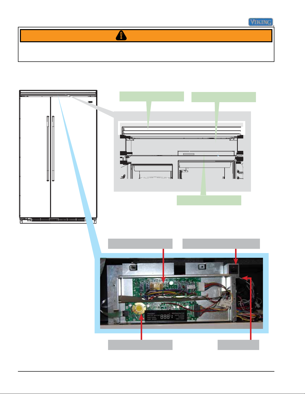
Parts Location–Control Panel
Upper Grille Assembly
Control Panel
Overlay Switch
Power Disconnect SwitchHigh Voltage Board
Low Voltage Board
12 ©2012 Viking Preferred Service
Inverter
Page 13
Disassembly
WARNING!
To avoid risk of electrical shock, personal injury, or death, disconnect electrical power source to unit, unless
test procedures require power to be connected. Ensure all ground wires are connected before certifying unit as
repaired and/or operational.
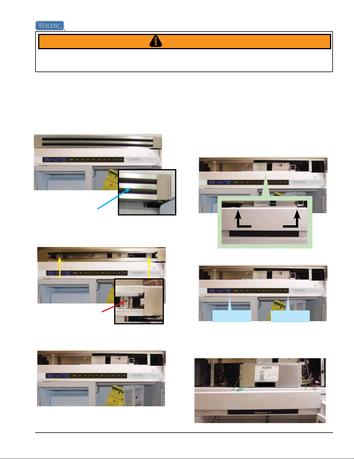
Upper Grille Assembly
Removal of the upper grille assembly allows
access to the control assembly.
1. To remove the upper grille assembly, slide
out the middle air louver.
Middle Air Louver
2. With the middle grille louver removed,
remove the (2) 1/4" hex screws securing
the grille assembly.
Control Panel
The control panel has an overlay switch
attached to it that allows user input to the
control boards.
1. To access the control panel, remove the
upper air grill assembly (see Upper Grill
Removal section), remove (2) screws
securing the control panel.
Screws
Remove 1/4" screw
on each side
3. Remove the grille assembly
2. Pull control panel from securing tabs.
Securing tab
3. Lower the control panel. Take caution with
the ribbon cable to prevent damage.
Securing tab
©2012 Viking Preferred Service 13
Page 14

Disassembly
O
O
WARNING!
To avoid risk of electrical shock, personal injury, or death, disconnect electrical power source to unit, unless
test procedures require power to be connected. Ensure all ground wires are connected before certifying unit as
repaired and/or operational.
Control Panel (continued)
4. Remove the four screws securing the
control board cover. Remove control
board cover.
5. Disconnect the door switches from the
back of the control panel.
7. Remove the two strain relief screws.
8. The control panel can now be removed
and the high voltage and low voltage
boards are accessible
9. Reverse procedure to reinstall
Overlay Switch
The unit uses an overlay switch to
communicate user input to the control boards.
The overlay connects to the control board via
a ribbon cable.
6. Disconnect the ribbon from the control
board.Take caution with the ribbon cable
to prevent damage.
1. To replace the overlay switch, remove
the upper air grill assembly, remove the
control panel (see Air Grill and Control
Panel Removal sections, Page 13).
2. Disconnect overlay switch from control.
Overlay Switch
Release tab and pull
connector out of socket.
14 ©2012 Viking Preferred Service
Page 15
Disassembly
WARNING!
To avoid risk of electrical shock, personal injury, or death, disconnect electrical power source to unit, unless
test procedures require power to be connected. Ensure all ground wires are connected before certifying unit as
repaired and/or operational.
Low Voltage BoardOverlay Switch (continued)
3. Peel overlay off control panel and remove
(remove adhesive to ensure replacement
overlay adheres properly)
4. Reverse procedure to reinstall.
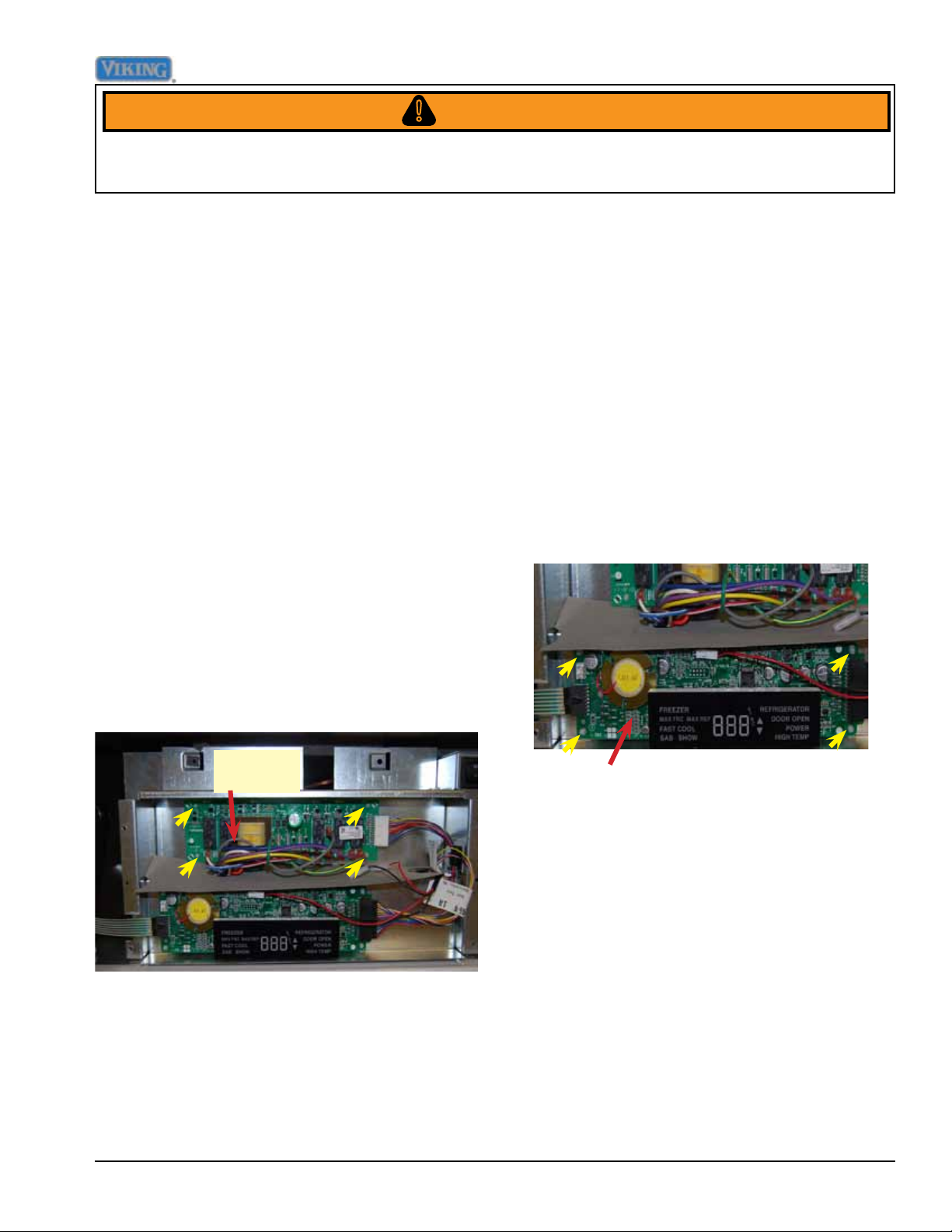
High Voltage Board
A control board is used to operate functions
of the unit. Once an input is received from
the low voltage board, the high voltage board
sends an output to activate the components.
1. To access the high voltage board, remove
the upper air grill assembly, and control
panel (see Air Grill and Control Panel
Removal sections, Page 13).
2. Compress plastic standoffs securing the
high voltage board and pull towards you.
The unit uses a control board in conjunction
with an overlay switch to operate functions
of the refrigerator/freezer. Interaction with
the low voltage board is via the ribbon cable
attached to the overlay switch.
1. To access the low voltage board, remove
the upper air grill assembly, control panel
(see Air Grill and Control Panel Removal
sections, Page 13).
2. Compress plastic standoffs securing low
voltage board, disconnect wiring and
remove.
HV Board
To check low voltage board, refer to chart on
Page 48.
High voltage board is now accessible.
To check high voltage board, refer to
chart on page 47..
3. Reverse procedure to reinstall.
©2012 Viking Preferred Service 15
LV Board
3. Reverse procedure to reinstall
Page 16
Disassembly
DANGER!
WARNING!
To avoid risk of electrical shock, personal injury, or death, disconnect electrical power source to unit, unless
test procedures require power to be connected. Ensure all ground wires are connected before certifying unit as
repaired and/or operational.
Power Disconnect Switch
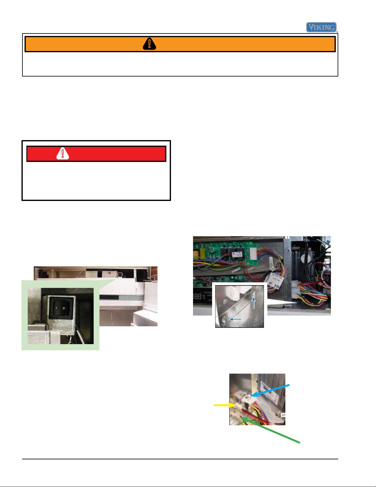
The unit has a rocker switch, located in the
upper right corner of the unit, that allows
power to the unit to be turned “OFF” without
removal of the unit.
ON/OFF switch has 120 vac connected
to one side of switch at all times, remove
power with circuit breaker box when
removing switch.
1. To access the power disconnect switch,
remove the upper air grill assembly (see
Air Grill Removal section, Page 13). The
power disconnect is now accessible on
the right side.
Inverter
The Compressor is operated by a Inverter
that varies the voltage to the compressor.
This is determined by the frequency input
from the low voltage board
1. To access the inverter, remove upper
air grill assembly, remove control panel
assembly (see Air Grill and Control Panel
Removal sections, Page 13).
2. Remove the control box in order to gain
easy access to the door hinge area for
service. There are 4 ¼” hex screws (2
on each side) holding the control box to
the refrigerator housing. Remove these
screws.
3. Unplug the 15-pin Molex power plug (A),
as well as the 2-wire converter frequency
Verify contacts 4-5 open when the switch
is in the “0” position and contacts 4-5 close
when in the “|” position. 120 VAC should be
measured when in the “0” position and 0 VAC
should be measured when in the “|” position.
2. Switch bracket is mounted on electronics
box with two 1/4" hex head screws.
3. Reverse procedure to reinstall.
16 ©2012 Viking Preferred Service
cable (B) and the 3-wire thermistor plug
(C).
Molex A
Molex
B
Molex C
Page 17
Disassembly
WARNING!
To avoid risk of electrical shock, personal injury, or death, disconnect electrical power source to unit, unless
test procedures require power to be connected. Ensure all ground wires are connected before certifying unit as
repaired and/or operational.
Inverter (continued)
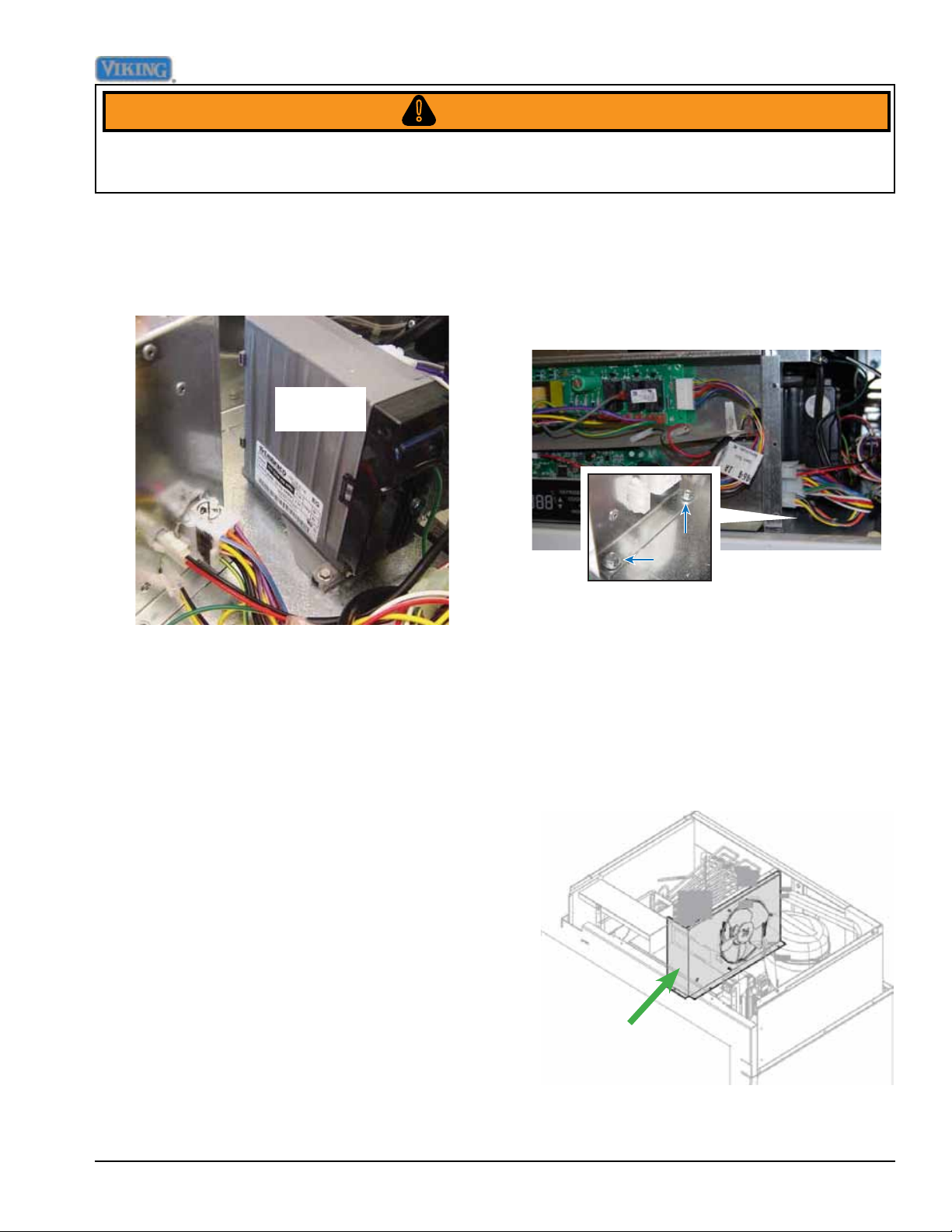
4. The inverter is now accessible on the right
side.
Inverter
120 VAC is supplied to the inverter
from E4 on the High Voltage Board.
The LV board sends 5 VDC to the
inverter to operate the compressor.
5. Reverse procedure to reinstall.
2. Remove the control box in order to gain
easy access to the door hinge area for
service. There are 4 ¼” hex screws (2
on each side) holding the control box to
the refrigerator housing. Remove these
screws.
3. Unplug the 15-pin Molex power plug, as
well as the 2-wire converter frequency
cable and the 3-wire thermistor plug .
Remove electronics box and set aside to
gain access to condenser fan assembly.
4. Remove the three 1/4" hex screws
holding fan assembly in place, remove
fan assembly
Condenser Fan
The condenser fan is located in the upper
machine compartment of the unit. 120 VDC
is supplied to the fan when the Compressor/
Condenser Fan relay closes to E4 on the
High Voltage Board.
1. To access the condenser fan assembly,
remove upper air grill assembly, remove
control panel assembly (see Air Grill and
Control Panel Removal sections, Page
13).
©2012 Viking Preferred Service 17
Condenser Fan
Page 18
Disassembly
WARNING!
To avoid risk of electrical shock, personal injury, or death, disconnect electrical power source to unit, unless
test procedures require power to be connected. Ensure all ground wires are connected before certifying unit as
repaired and/or operational.
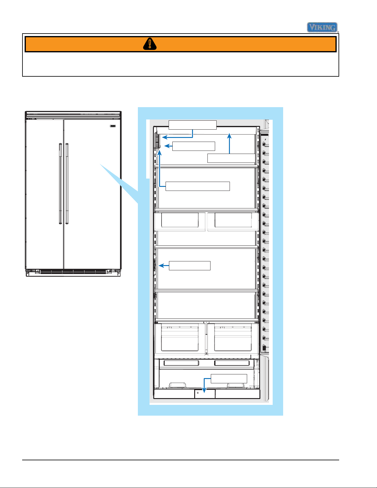
Parts Location–Refrigerator Compartment
Plasma Cluster
Fan Assembly
Light Assembly
Ref Thermistor
Interior light
Water filter
18 ©2012 Viking Preferred Service
Page 19
Disassembly
WARNING!
To avoid risk of electrical shock, personal injury, or death, disconnect electrical power source to unit, unless
test procedures require power to be connected. Ensure all ground wires are connected before certifying unit as
repaired and/or operational.
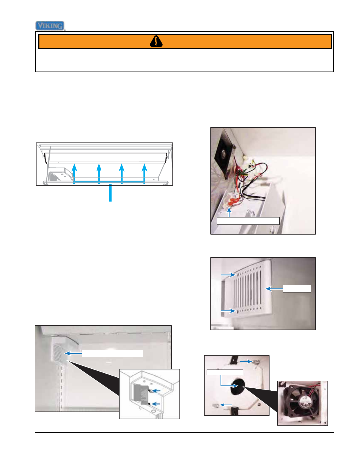
Light Assembly
The unit uses 40 watt bulbs to light the unit.
The bulbs are located at the top of unit.
To access bulbs, remove light cover and bulb
is accessible.
Bulbs
To check bulb, verify lament is not broken,
resistance in the bulb, and voltage is
supplied to the socket.
Fresh Food Fan Assembly
The Side-by-Side units uses a fresh food fan to
circulate air through the refrigerator compartment
The fresh food fan is wired in parallel with the cross
over fan. When the board calls for the fan to operate,
24 VDC is sent to the fan via the E1 (Purple) at the
H.V. Board.
1. To access the fan, open the refrigerator
door and remove the upper shelf.
Remove (2) screws securing fan cover.
2. Lower fan cover to expose fresh food fan
and disconnect wiring.
Fresh Food thermistor
3. Open freezer door and remove (2) screws
securing air cover.
Air cover
4. Remove (2) screws securing fresh food
fan and repair/replace fan.
Fresh Food fan cover
Fresh food fan
©2012 Viking Preferred Service 19
Page 20
Disassembly
WARNING!
To avoid risk of electrical shock, personal injury, or death, disconnect electrical power source to unit, unless
test procedures require power to be connected. Ensure all ground wires are connected before certifying unit as
repaired and/or operational.
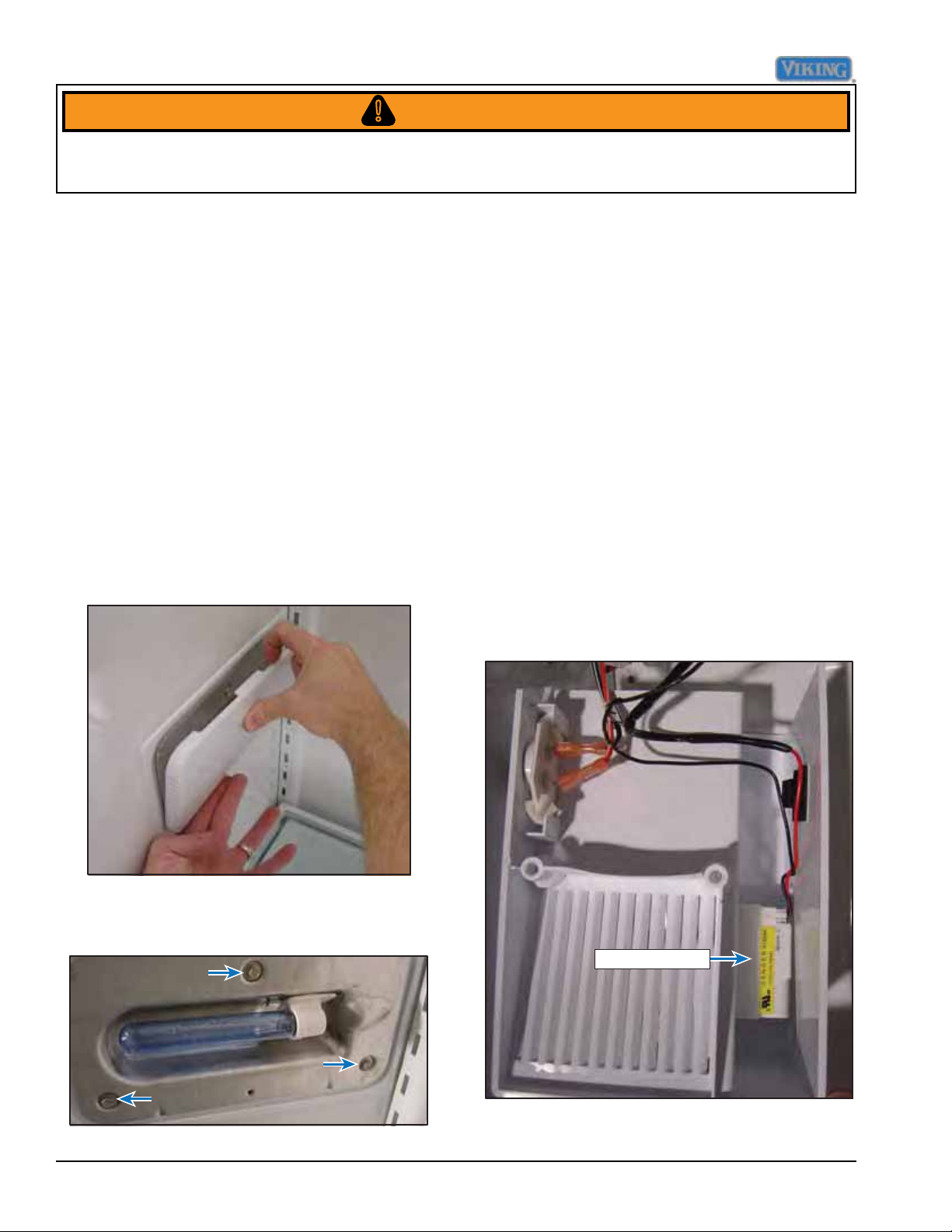
Interior Lights
The unit uses two lights, one in the fresh
food section and one in the freezer section,
to provide lighting for the cabinet.
1. To access the light bulb, remove shelves.
2. Remove light cover. The fresh food light
cover is removed by pressing up on the
bottom of cover while gently pulling out
on the top of the cover to release the
cover tab from the mounting plate. The
freezer light cover is removed by pushing
down on the top of the light cover while
gently pulling out on the bottom of the
cover to release the cover tab from the
mounting plate.
4. Remove the light assembly and replace/
repair the socket.
5. Reverse procedure to reinstall.
Plasma Cluster™
The Plasma Cluster™ ion air purier uses
ions to eliminate airborne bacteria, mold
spores, and food odors without having to be
replaced.
1. To access the plasma cluster, remove
air cover (see fresh food fan procedure,
Page 19).
2. With cover removed, remove the double
sided tape securing the plasma cluster
to the air cover, disconnect wiring, and
repair/replace plasma cluster.
3. Remove the three securing screws to
access the socket.
Plasma Cluster
3. Reverse procedure to reinstall.
20 ©2012 Viking Preferred Service
Page 21
Disassembly
WARNING!
To avoid risk of electrical shock, personal injury, or death, disconnect electrical power source to unit, unless
test procedures require power to be connected. Ensure all ground wires are connected before certifying unit as
repaired and/or operational.
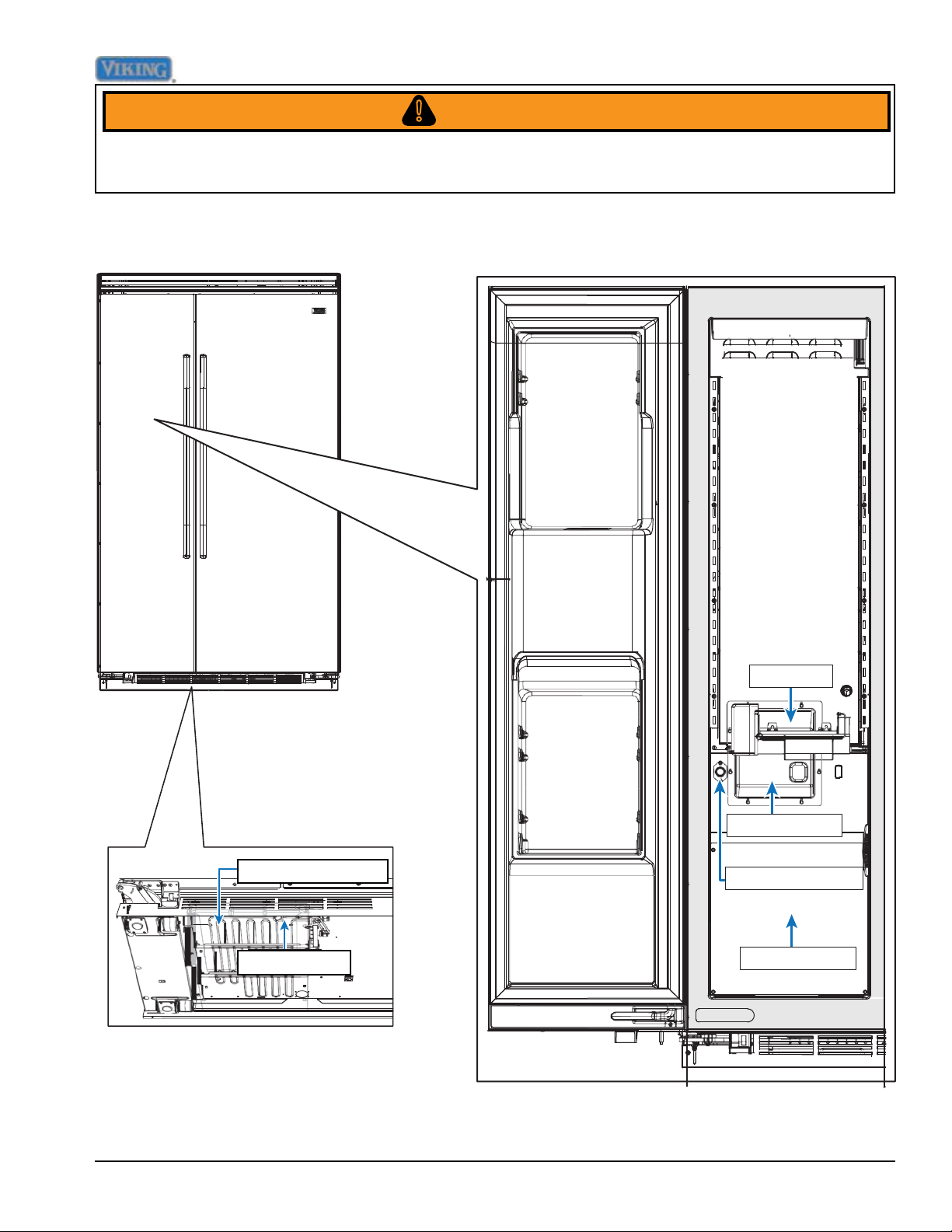
Parts Location–Freezer Compartment and Lower Unit–Non Dispenser
Drain Pan heater
Float Switch
Icemaker
Evaporator Fan
Freezer thermistor
Defrost heater
©2012 Viking Preferred Service 21
Page 22
Disassembly
WARNING!
To avoid risk of electrical shock, personal injury, or death, disconnect electrical power source to unit, unless
test procedures require power to be connected. Ensure all ground wires are connected before certifying unit as
repaired and/or operational.
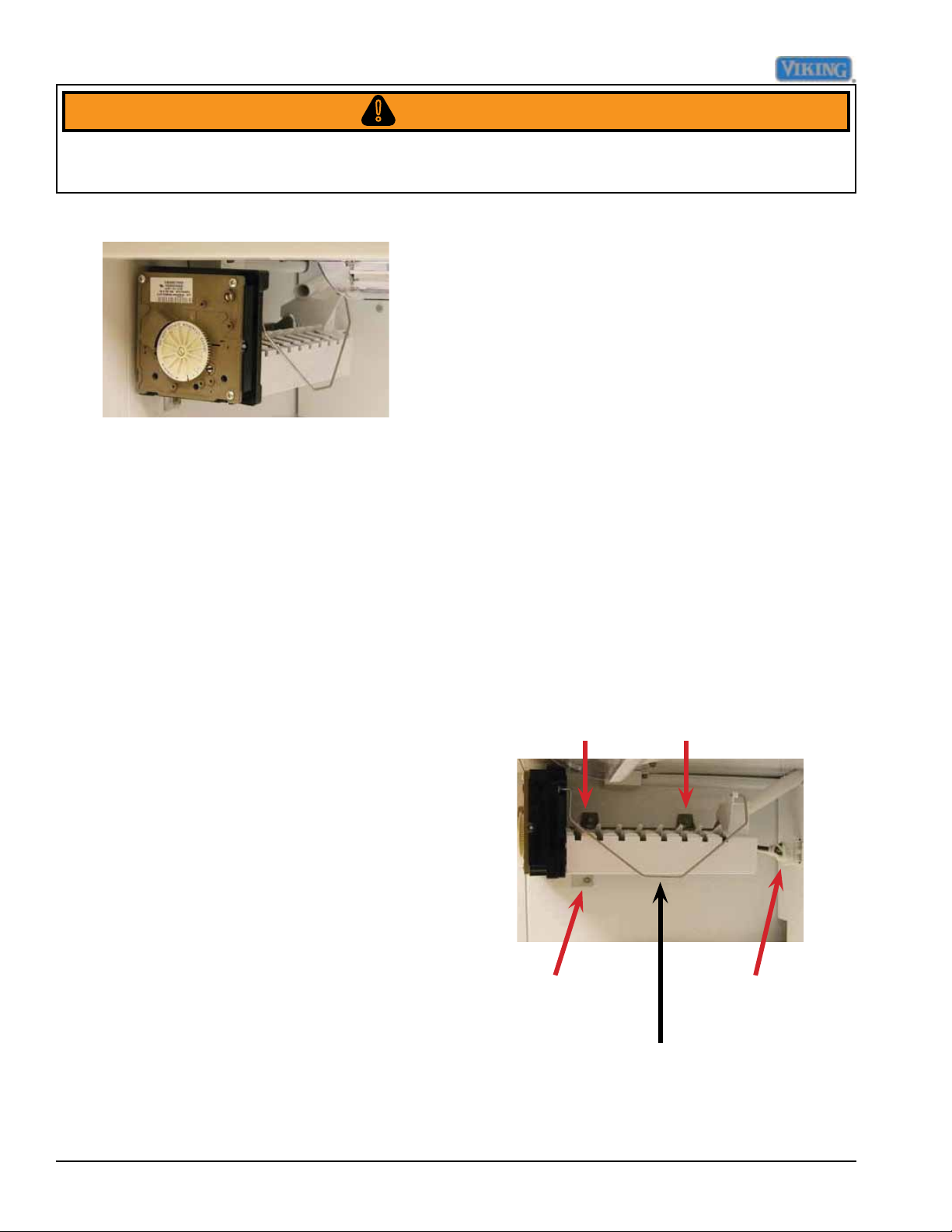
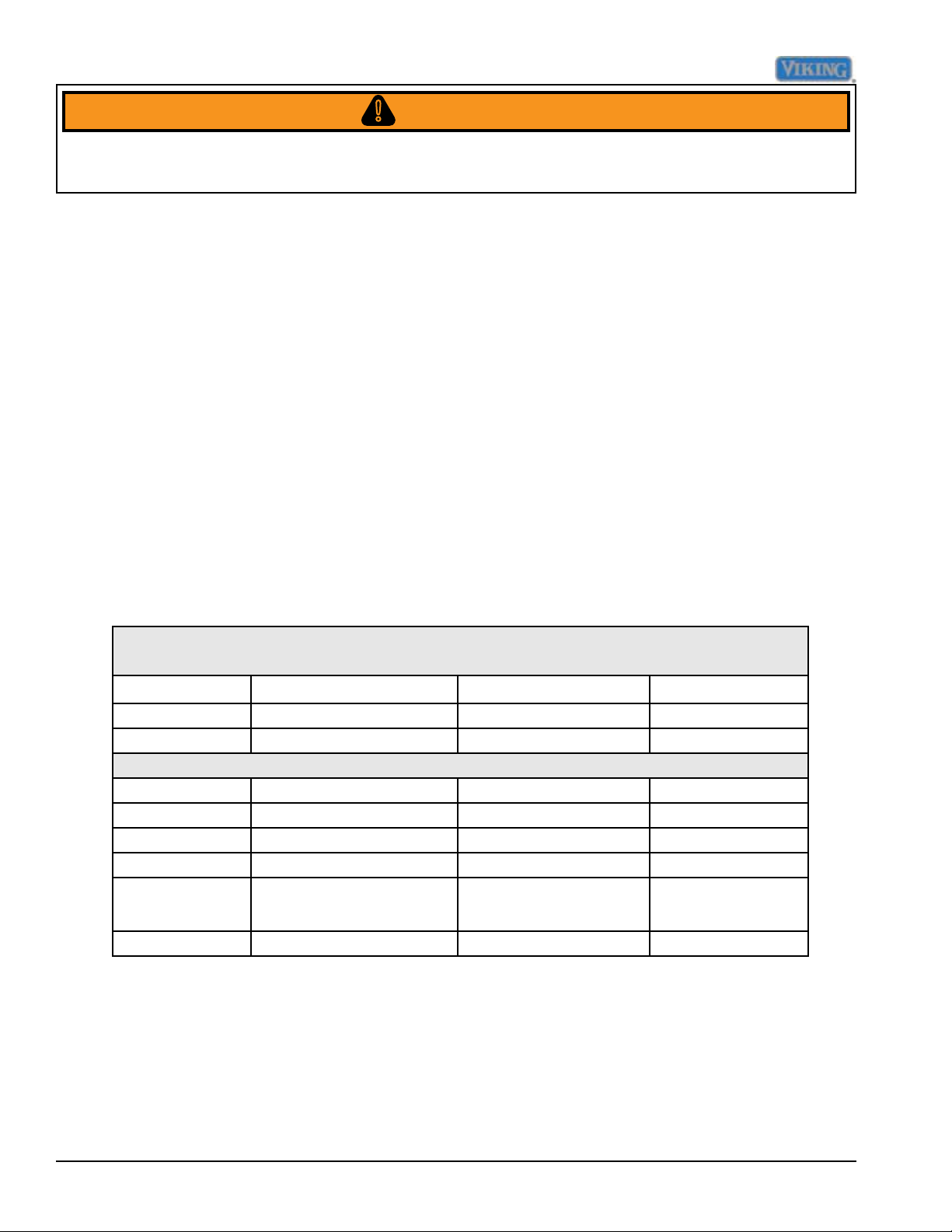
Ice Maker (shown here with cover off)
The unit uses an ice maker that consists of
a mold heater, thermostat, motor, and wire
harness. The ice maker always starts from
and stops at the “park” position. In the park
position (the ejector blades
are pointing horizontally towards the back
of the ice maker). Just before reaching the
park, position the mold is lled with water. At
the park position all electrical components
are de-energized, even
though the shut-off arm is down, and the ice
maker is ready for the next freeze cycle. The
ice maker takes from 30 minutes to one hour
to freeze the water. The primary time factors
are the temperature in the freezer and the
amount of airflow around the ice maker.
Colder freezer settings and free air space
around the ice maker to let air circulate will
help make ice faster. After the ice forms, the
ice maker continues to wait until it reaches
15ºF before it
starts the harvest cycle. This ensures that
the ice is solid in all the cavities. At 15ºF the
thermostat closes, the mold heater turns on,
and the ejector blades rotate up and forward
until they stall out against the ice. The motor
is designed to stall out and is geared to
generate a lot of pressure. This minimizes
the amount of melting needed to extract
the ice. As soon as the ice is loose enough
to move, the ejector pushes the ice out of
the mold during the second half of the rst
revolution. During the second revolution, the
ejector pushes the ice into the bucket.
Just before the ejector completes the second
revolution, the ice maker turns the water
valve on for approximately 7 seconds and
rells the mold with approximately 4 ounces
of water and the freezing cycle is ready to
begin again.
To access the ice maker, open the freezer
door, remove bottom cover and the ice maker
is accessible.
To access module, motor, and support
assembly loosen screws in module access
ports, disconnect shutoff arm, disconnect
wiring harness and remove mold from
support assembly.
Mounting screws
Mounting screw
Shutoff arm
Wire Harness
22 ©2012 Viking Preferred Service
Page 23
Disassembly
WARNING!
To avoid risk of electrical shock, personal injury, or death, disconnect electrical power source to unit, unless
test procedures require power to be connected. Ensure all ground wires are connected before certifying unit as
repaired and/or operational.
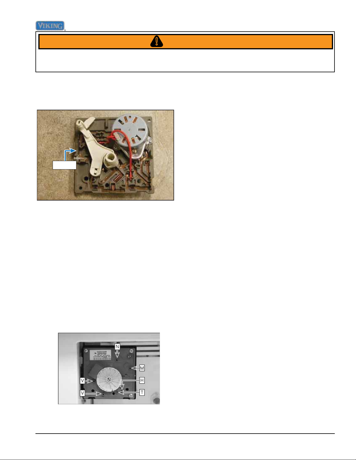
To access module and heater assembly,
remove three screws on front of module and
remove support assembly.
Module
To make ice, an ice maker needs power,
water, and sub-freezing temperatures.
Note: The freezer door switch turns off
power to the ice maker when the freezer
door is open. It will be necessary to manually
close the freezer door switch for some
troubleshooting steps. Ensure that the shutoff arm is down and instruct customer on its
use if necessary.
To ensure power to the ice maker without a
meter, remove the module cover and take
note of the test points.
N - Neutral side of line voltage
M - Motor connection
H - Heater connection
T - Thermostat connection
L - L1 (hot)side of line voltage
V - Water valve connection
Place a 14 gauge jumper wire across test
points T and H. With hands clear of the
ice maker, manually close the freezer door
switch. This will put the ice maker in a
manual cycle. If the ejector does not rotate,
this indicates no power to the ice maker.
Trace power from the wall socket to the door
switch and to the connector. Repair circuit
and connections or replace door switch as
needed. If the ejector begins to rotate (very
slowly) there is power. With power present,
verify 0 VAC between test points
T and H (this veries the thermostat
has closed). Verify heater resistance is
approximately 264 Ω. With motor running,
verify heater is heating. If no heat is
detected, replace mold assembly. Next
ensure water is supplied to the ice maker.
When the ejector blade gets to the 11:00
position, the water valve is energized for 7.5
seconds.
Verify the water valve has 120 VAC between
test points V and N and approximately 4.75
ounces of water is dispensed. If voltage is
present and water is not dispensed verify
water supply and ll rate. Poor water quality
can cause ice maker to fail or produce
unacceptable cubes. Install a water lter
©2012 Viking Preferred Service 23
Page 24
Disassembly
WARNING!
To avoid risk of electrical shock, personal injury, or death, disconnect electrical power source to unit, unless
test procedures require power to be connected. Ensure all ground wires are connected before certifying unit as
repaired and/or operational.
to eliminate bad taste, odor, and visible
contaminates. Mineral content or sand can
restrict screen in water ll valve or particles
of sand can keep valve from seating
properly.
If water valve does not operate properly,
the following could occur: no ice production,
small or hollow ice cubes, flooding of ice
container. Mineral content can cause lime
build up in the mold, wicking of water over
the mold and poor cube release. Mineral
content can also restrict saddle valves. Verify
water supply line is “ON”, water pressure is
not below 20 psi, saddle valve
Module Ohmmeter Checks No power to icemaker and Ejector blades in end
Test Points Component Module Position Ohms
is fully open clear restrictions by fully closing
and opening valve to dislodge sediment
(if necessary, remove valve and enlarge
pierced hole to 3/16” diameter with a drill
and reinstall saddle valve) ensure water
line to unit is not pinched/kinked/ clogged,
ice is not present in inlet tube blocking
water flow, water pressure is not above 120
psi. Water ll can be increased by turning
the adjustment screw counterclockwise
and decreased by turning the screw
clockwise. One half turn will adjust the ll
by approximately two thirds of an ounce.
If supply is OK replace water valve. If no
voltage is present, verify harness. If OK,
replace module.
of cycle
L-H Mold & Heater Attached to support 264
L-M Motor Separate from heater 16,100
Module Voltage checks with motor or test light power to icemaker
Test Points Component Line Voltage 0 Volts
L-N Module Power On Power Off
T-H Bimetal Open Closed
L-H Heater On Off
L-M Motor On Off
N-V Water valve On Off
24 ©2012 Viking Preferred Service
Page 25
Disassembly
WARNING!
To avoid risk of electrical shock, personal injury, or death, disconnect electrical power source to unit, unless
test procedures require power to be connected. Ensure all ground wires are connected before certifying unit as
repaired and/or operational.
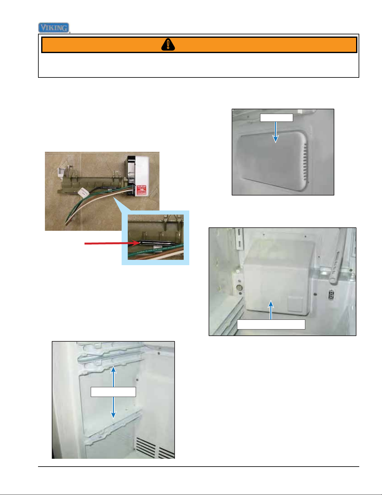
Thermal Cut Out (TCO)
The TCO is a safety device and must NOT
be bypassed. If the TCO is found to be
electrically open, this indicates an overheat
in the ice maker and the ice maker must be
replaced.
TCO
3. Remove right side light lens (see interior
lights page 53).
Light lens
4. Remove screws and center evaporator
cover.
Freezer Evaporator Fan
1. Remove lower freezer baskets.
2. Remove screws securing left and right
freezer glides and remove glides.
Freezer glides
Evaporator Fan Cover
©2012 Viking Preferred Service 25
Page 26
Disassembly
WARNING!
To avoid risk of electrical shock, personal injury, or death, disconnect electrical power source to unit, unless
test procedures require power to be connected. Ensure all ground wires are connected before certifying unit as
repaired and/or operational.
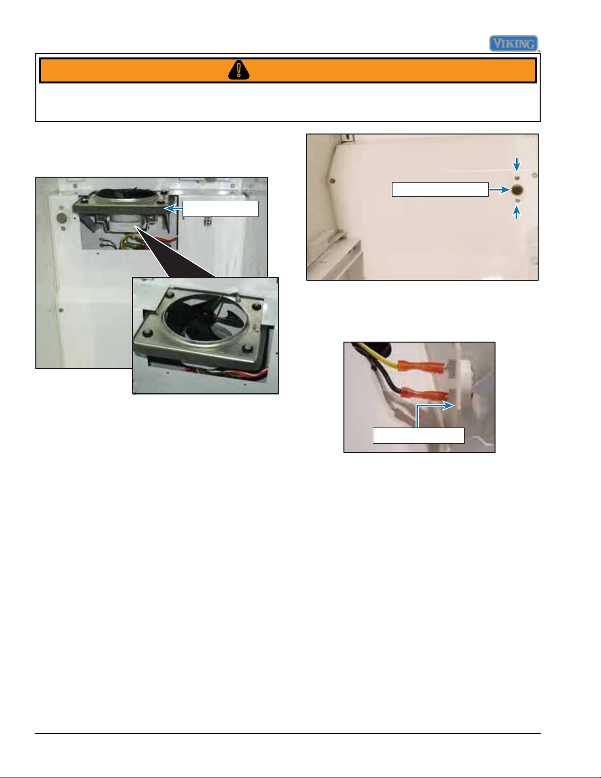
5. Disconnect wiring, and repair/replace
freezer fan.
Evaporator Fan
6. Reverse procedure to reinstall.
Freezer thermistor
3. Pull thermistor into freezer cabinet,
disconnect wiring, repair/replace
thermistor.
Freezer Thermistor
The freezer uses the same thermistor as
does the fresh food section however, the
freezer thermistor controls the cycle of
the compressor. As the temperature in the
compartment changes, the resistance in
this device changes. These changes are
measured by the low voltage board, and
controls the operation of the compressor,
condenser, and freezer evaporator fan.
Refer to the thermistor chart on page 11.
To access the freezer thermistor:
1. Remove drawers and shelves.
2. Remove screws securing the thermistor.
Freezer thermistor
4. Reverse procedure to reinstall.
Defrost Heater
The unit use a heater to help remove ice
build up during the defrost cycle. When the
defrost terminator closes, voltage is supplied
to the heater via the control board. With the
main power switch OFF, the defrost Heater
can be tested by removing the orange wire
off of terminal E6 on the HV board. Using
an ohm meter, check the brown wire and
Neutral and you should read approximately
30 Ω. During the defrost cycle Line voltage
passes through the Defrost Terminator the
into terminal E5 (orange wire). With the
defrost heater relay activated, the voltage
26 ©2012 Viking Preferred Service
Page 27
Disassembly
WARNING!
To avoid risk of electrical shock, personal injury, or death, disconnect electrical power source to unit, unless
test procedures require power to be connected. Ensure all ground wires are connected before certifying unit as
repaired and/or operational.
exits the HV board from Terminal E6 (orange)
to the heating element If voltage is present
at E5 but not at E6, then the Defrost relay
is open. If there is 0 volts At E5, then the
terminator is open.
Another method to test can be achieved by
testing at the 15-wire Molex plug on the right
side of the Control Housing. Refer to page
82 pin locations.
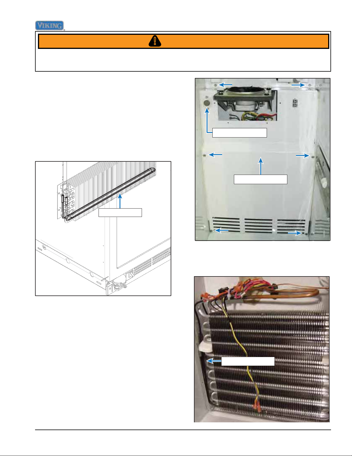
Defrost heater
Freezer thermistor
Evaporator cover
1. Remove screws securing rear panel and
remove rear panel.
2. Remove clips securing defrost heater,
disconnect wiring, and repair/replace
defrost heater.
Defrost heater
©2012 Viking Preferred Service 27
Page 28
Disassembly
WARNING!
To avoid risk of electrical shock, personal injury, or death, disconnect electrical power source to unit, unless
test procedures require power to be connected. Ensure all ground wires are connected before certifying unit as
repaired and/or operational.
3. Reverse procedure to reinstall.
Defrost Terminator
The defrost terminator is a bimetal switch
that is normally open. Below 20+/-8.5 ˚F,
the terminator is closed. In order to test, rst
switch the main power switch to “Off”. Locate
the brown wire on E5 of the HV board.
Unplug the wire and check for continuity
between the brown wire and the black wire
at E10. If “0” is read then the bimetal is
closed. It innity (∞) is read, the bimetal is
open.
Note: Freezer temp must be below 20+/-8.5
˚F in order to check for a defective bimetal.
Another method to test can be achieved by
testing at the 15-wire Molex plug on the right
side of the Control Housing. Refer to page
82 pin locations.
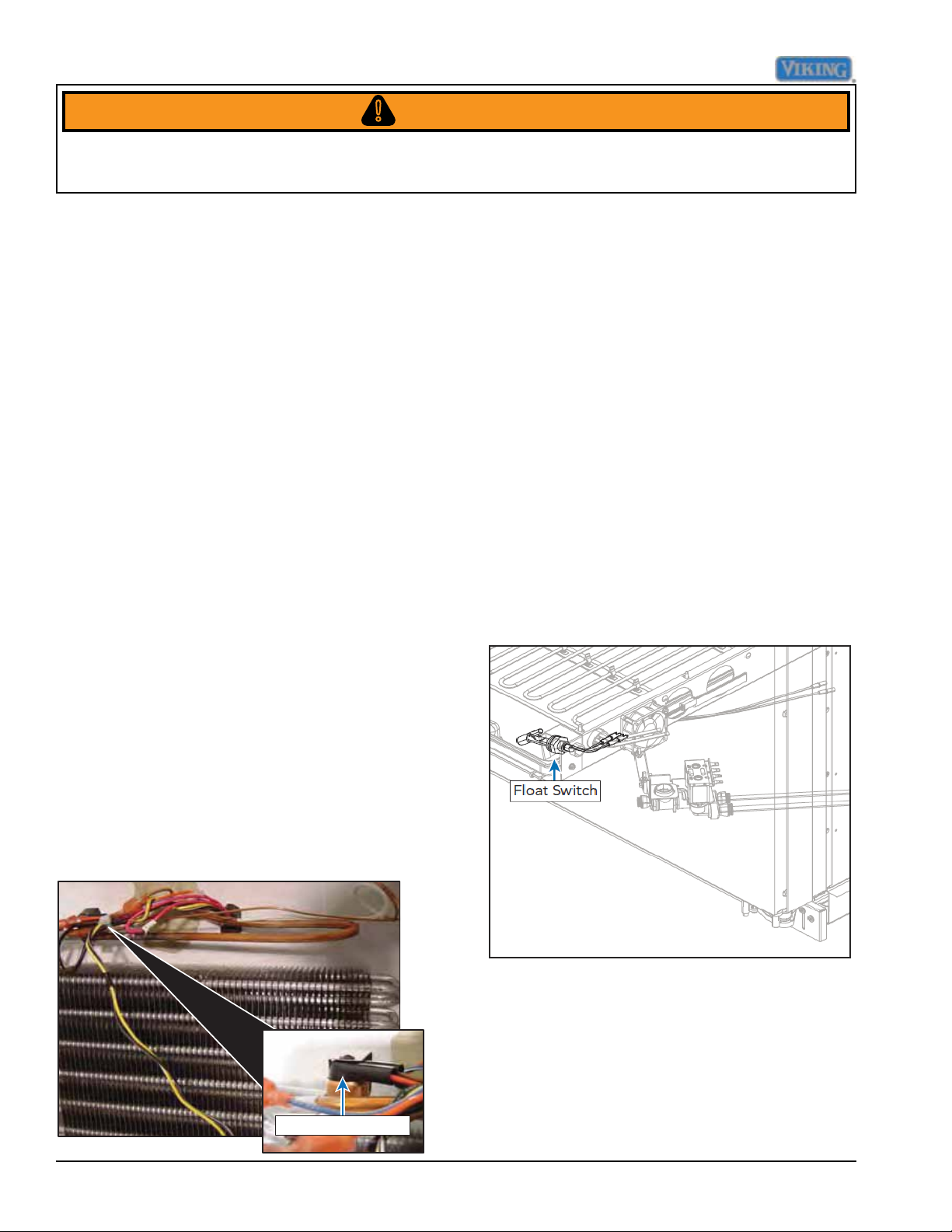
Float Switch
The unit uses a float switch in conjunction
with the drain pan heater to vaporize
condensate created from the refrigerator
cooling process. The switch is normally open
and closes as the water level in the pan
rises thus energizing the drain pan heater.
When the water is vaporized the switch
opens removing power from the drain pan
heater.
To access the float switch, remove the lower
access panel and the float switch is now
accessible. Verify the switch reads innite
resistance when in the down position and
0 Ω in the up position. If the switch does
not open or close properly, replace the float
switch.
To access the defrost terminator:
1. Follow steps 1-4 under Defrost Heater
disassembly.
2. Unclip the terminator, disconnect wiring,
repair/ replace terminator.
Defrost Terminator
28 ©2012 Viking Preferred Service
Page 29
Disassembly
WARNING!
To avoid risk of electrical shock, personal injury, or death, disconnect electrical power source to unit, unless
test procedures require power to be connected. Ensure all ground wires are connected before certifying unit as
repaired and/or operational.
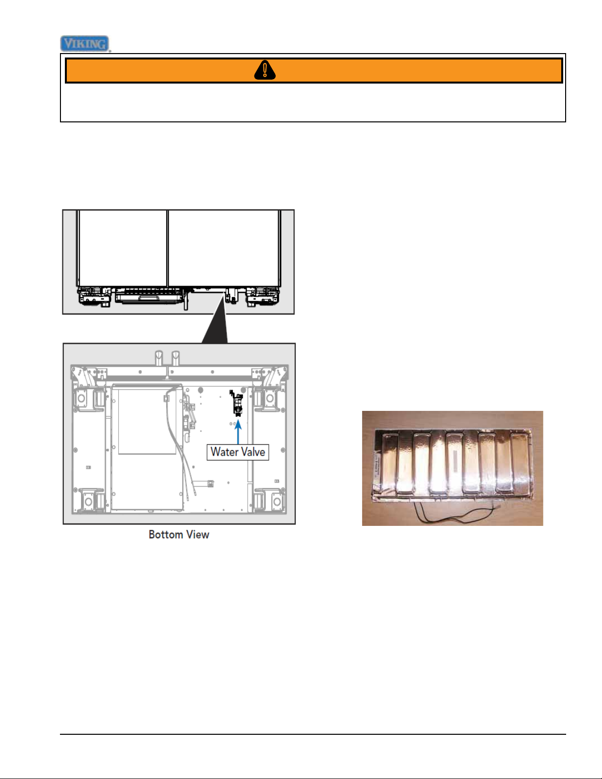
Water Valve
The Non-Dispenser Side-by-Side models
utilize a single coil water valve to ll the ice
maker when required.
Drain Pan Heater
The unit uses a drain pan heater to
evaporate condensate created by the
refrigerator cooling process. The pan heater
is energized once the float switch closes
supplying 120 VAC.
To access the drain pan heater, remove
the lower access panel and the drain pan
heater is accessible. Verify the resistance is
approximately 790 Ω.
Verify 120 VAC to the heater and the float
switch is closed. If the switch is closed and
no voltage is supplied, verify wiring, power
disconnect switch has not been turned “ON”,
and supply voltage. If voltage is supplied, the
float switch is closed, and the heater does
not energize, replace the heater.
©2012 Viking Preferred Service 29
Page 30
Service Procedures
Program Modes
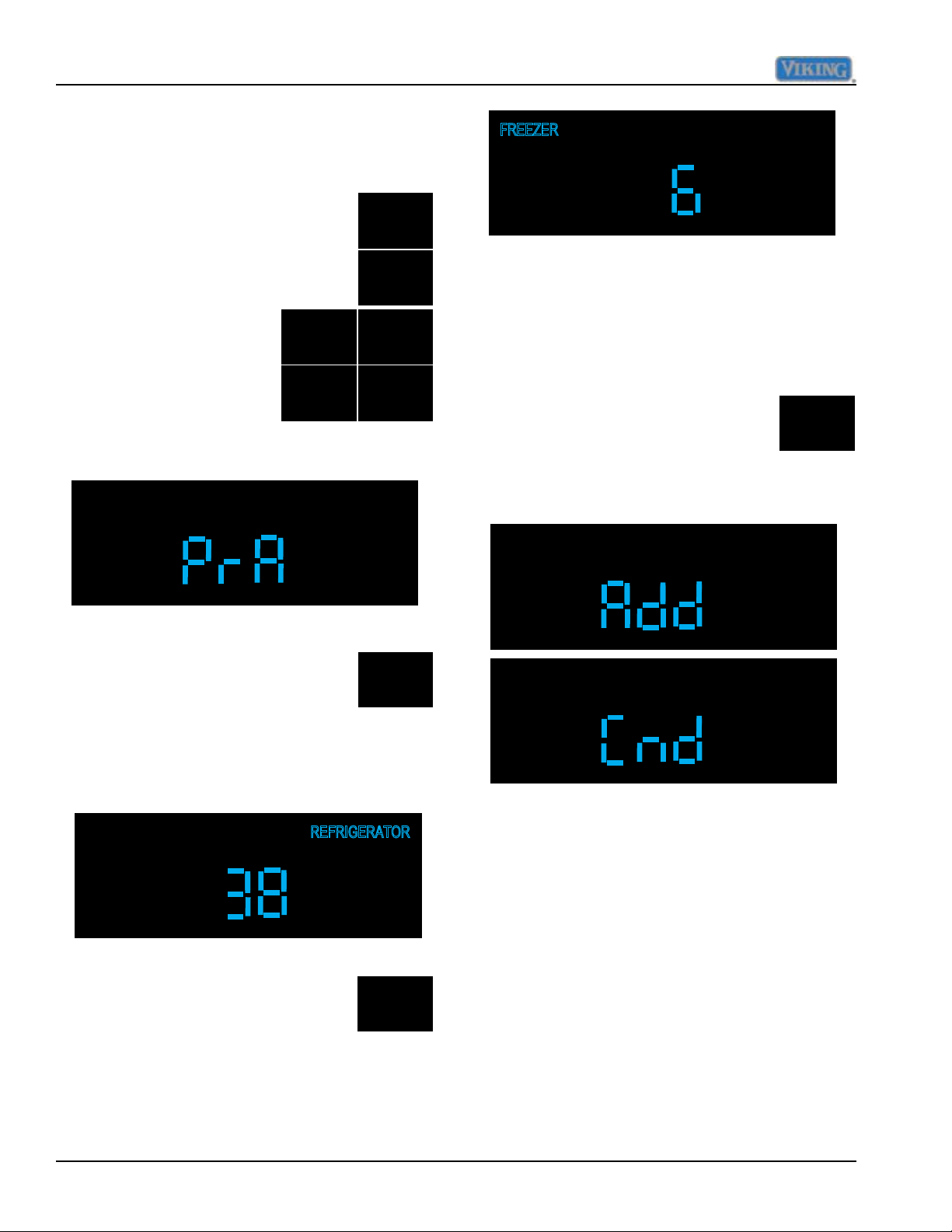
Program Mode A
Program mode A is entered by first
pressing and releasing "ACTIVATE
CONTROLS", then press and
release "FAST COOL" once and
within five seconds press and
release the following pads
in sequence, "HIGHER,
LOWER, HIGHER,
LOWER" You will hear an
audible three beeps and
the numeric display will
change to "PrA", see illustration
below.
HIGHER
HIGHER
ACTIVATE
CONTROLS
FAST
COOL
LOWER
LOWER
Defrost mode selection
Unit is shipped in Adaptive defrost mode,
this can be changed to Conventional defrost
mode using the following procedure while in
Mode A.
Press the "FAST COOL" pad once
to display the current defrost mode.
FAST
COOL
This will result in a display of "Add"
for adaptive or "Cnd" for conventional as
shown in the illustrations below.
Display Ref Temperature
Press "REF TEMP" pad once to
display the value of the thermistor
temperature with the offset, no
filtering is applied to the display.
This readout will reflect instantaneous
temperature changes on the refrigerator
thermistor as shown below.
Display Frz Temperature
Press "FRZ TEMP" pad once to
display the value of the thermistor
temperature with the offset, no
filtering is applied to the display.
This readout will reflect instantaneous
temperature changes on the freezer
thermistor as shown in illustration, next
column.
REF
TEMP
FRZ
TEMP
At this point pressing and releasing the
"FAST COOL" pad will toggle between
adaptive and conventional defrost modes of
operation.
Conventional defrost time adjustment
(CRTD)
The conventional defrost is adjusted based
upon compressor run time between defrost
cycles (CRTD). This time can be adjusted
from between 4 hours (minimum) to 24 hours
(maximum) in one hour increments.
Conventional defrost must first be selected as
shown in previous step.
30 ©2012 Viking Preferred Service
Page 31

Service Procedures
Press and hold the "ALARM OFF"
pad for three seconds until you
ALARM
OFF
hear 3 audible beeps and the
display changes to "cd".
Pressing the "HIGHER or LOWER"
pads will result in number of hours
HIGHER
being displayed and can be
adjusted in one hour increments
from 4 hours to 24 hours CRTD
LOWER
interval.
To exit this time period adjustment press and
release "ACTIVATE CONTROLS" one time
which will result in "PrA" being displayed. You
are now back in Mode A.
Compressor low speed frequency
Pressing and releasing "HIGHER or
LOWER" pads will bring the numeric
HIGHER
display up, pressing and releasing
changes in increments of 1 HZ,
LOWER
holding the key down changes in
increments of 5 HZ.
This value should be set at 75HZ for side by
side model refrigerator,s see Table 1 on Page
42.
To exit the low speed adjustment press and
release "ACTIVATE CONTROLS" one time
which will result in "PrA" being displayed. You
are now back in Mode A.
Adjust Cut-In Hysteresis
Cut-In hysteresis for the refrigerator and
freezer is set to predetermined values, based
upon model of refrigerator. This value can
be set in Mode A as a separate adjustment
or can be set automatically in Mode C when
selecting model code, where several control
values are set by eeprom. Table 1 on Page
42 lists eeprom values set by model code.
Compressor low speed frequency is set to a
predetermined value based upon model of
refrigerator. This value can be set in Mode
A as a separate adjustment or can be set
automatically in Mode C when selecting
model code, where several control values
are set by eeprom. Table 1 on Page 42 lists
eeprom values set by model code.
To enter low speed frequency adjustment
in Mode A, press and release
"DISPLAY OFF" once, this will
DISPLAY
OFF
result in the display "CLF".
While still in Mode A press and hold
"ALARM OFF" and then "HIGHER"
pad for three seconds, the display
will change to "CIH".
Press "REF TEMP to select
the refrigerator compartment,
the display will illuminate
"REFRIGERATOR" on display.
Next Press and release "HIGHER
or LOWER" which will result in
displaying degrees in Fahrenheit.
For the refrigerator section this
ALARM
OFF
HIGHER
REF
TEMP
HIGHER
LOWER
©2012 Viking Preferred Service 31
Page 32
Service Procedures
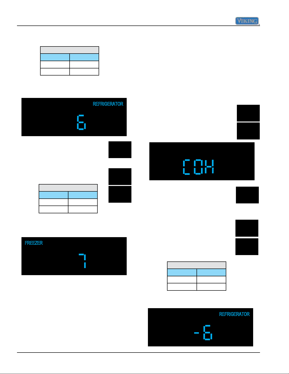
should be set to appropriate value in
table below
Refrigerator Cut-In
Model Value
5421 6
5481 6
Using Higher and Lower pads set to correct
value as in illustration below.
Press and release "FRZ TEMP",
this will result in "FREEZER"
FRZ
TEMP
illuminating on display.
Adjust Cut-Out Hysteresis
Cut-Out hysteresis for the refrigerator and
freezer is set to predetermined values, based
upon model of refrigerator. This value can
be set in Mode A as a separate adjustment
or can be set automatically in Mode B when
selecting model code, where several control
values are set by eeprom.Table 1 on Page 42
lists eeprom values set by model code.
While still in Mode A press and hold
"ALARM OFF" and then"LOWER"
ALARM
OFF
pad at the same time for three
seconds, the display will change to
HIGHER
"COH".
The freezer section should be set to
appropriate value in table below.
Freezer Cut-In
Model Value
5421 7
5481 7
HIGHER
LOWER
Using Higher and Lower pads set to correct
value as in illustration below.
To exit the cut-in adjustment press and
release "ACTIVATE CONTROLS" one time
which will result in "PrA" being displayed. You
are now back in Mode A.
Press "REF TEMP to select
the refrigerator compartment,
REF
TEMP
the display will illuminate
"REFRIGERATOR" on display.
Next Press and release "HIGHER
or LOWER" which will result in
HIGHER
displaying degrees in Fahrenheit.
For the refrigerator section this
should be set to appropriate value
LOWER
in table below.
Refrigerator Cut-Out
Model Value
5421 -6
5481 -6
Using Higher and Lower pads set to correct
value as in illustration below.
32 ©2012 Viking Preferred Service
Page 33
Service Procedures
Press and release "FRZ TEMP",
this will result in "FREEZER"
FRZ
TEMP
illuminating on display.
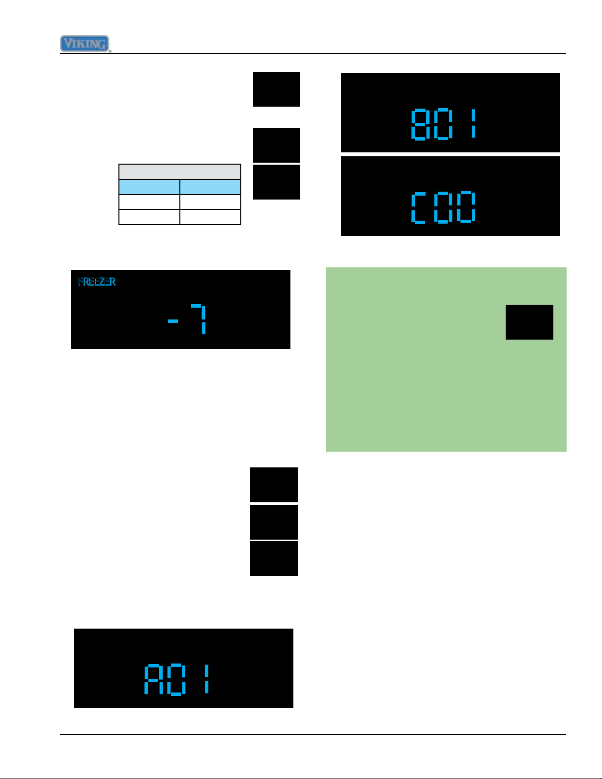
The freezer section should be set to
appropriate value in table below.
Freezer Cut-Out
Model Value
5421 -7
5481 -7
HIGHER
LOWER
Using Higher and Lower pads set to correct
value as in illustration below.
To exit the cut-out adjustment press and
release "ACTIVATE CONTROLS" one time
which will result in "PrA" being displayed. You
are now back in Mode A.
Display Software Version
Exiting Mode A
To exit Mode A and retain any changes
made in system up to this point
you must press and hold
"ACTIVATE CONTROLS" for
ACTIVATE
CONTROLS
three seconds until you hear
three audible beeps. This signifies
that the changes were written to the
eeprom and that the system has
left Mode A and returned to normal
operation. Failure to do this will cause
system to time out after 10 minutes
and any changes will be lost.
While in Mode A, press and hold
"DISPLAY OFF" for three seconds
DISPLAY
OFF
to show the software version on
the temperature display. Pressing
HIGHER
"HIGHER or LOWER" will cycle
between a letter prefix and a two
digit version as follows:
LOWER
"A" + the major version
"B" + the minor version
"C" the build number
©2012 Viking Preferred Service 33
Page 34
Service Procedures
Program Mode B
If you are not already in Mode A, go back to
Mode A instructions on Page 30.
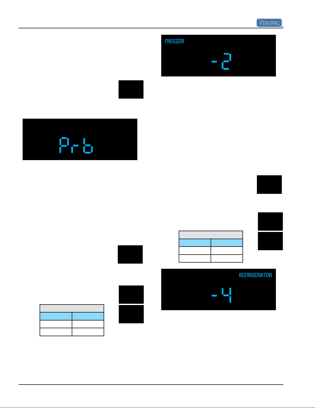
Once you are in Mode A (PrA in display),
press and release "ACTIVATE
CONTROLS" one time and display
will change to "Prb", signifying that
control is now in Program Mode B,
see illustration below.
ACTIVATE
CONTROLS
Adjust Refrigerator Temperature Offset
Refrigerator temperature offset is a
predetermined value, based upon model of
refrigerator. This value can be set in Mode
B as a separate adjustment or can be set
automatically in Mode B when selecting
model code, where several control values
are set by eeprom. Table 1 on Page 42 lists
eeprom values set by model code.
Adjust Freezer Temperature Offset
Freezer temperature offset is a
predetermined value, based upon model of
refrigerator. This value can be set in Mode
B as a separate adjustment or can be set
automatically in Mode B when selecting
model code, where several control values
are set by eeprom. Table 1 on Page 42 lists
eeprom values set by model code.
Press and release "FRZ TEMP"
pad once, the "FREEZER"
FRZ
TEMP
indicator will illuminate and the
current freezer offset will be
o
displayed along with
This value should be set to
appropriate value in table below.
Freezer Offset
Model Value
5421 -2
5481 -5
F.
HIGHER
LOWER
Press and release "REF TEMP"
pad once, the "REFRIGERATOR"
indicator will illuminate and the
current refrigerator offset will be
o
displayed along with
F.
This value should be set to
appropriate value in table below.
Refrigerator Offset
Model Value
5421 -6
5481 -4
REF
TEMP
HIGHER
LOWER
Using "HIGHER and LOWER" pads adjust
value as in illustration below.
34 ©2012 Viking Preferred Service
Page 35
Service Procedures
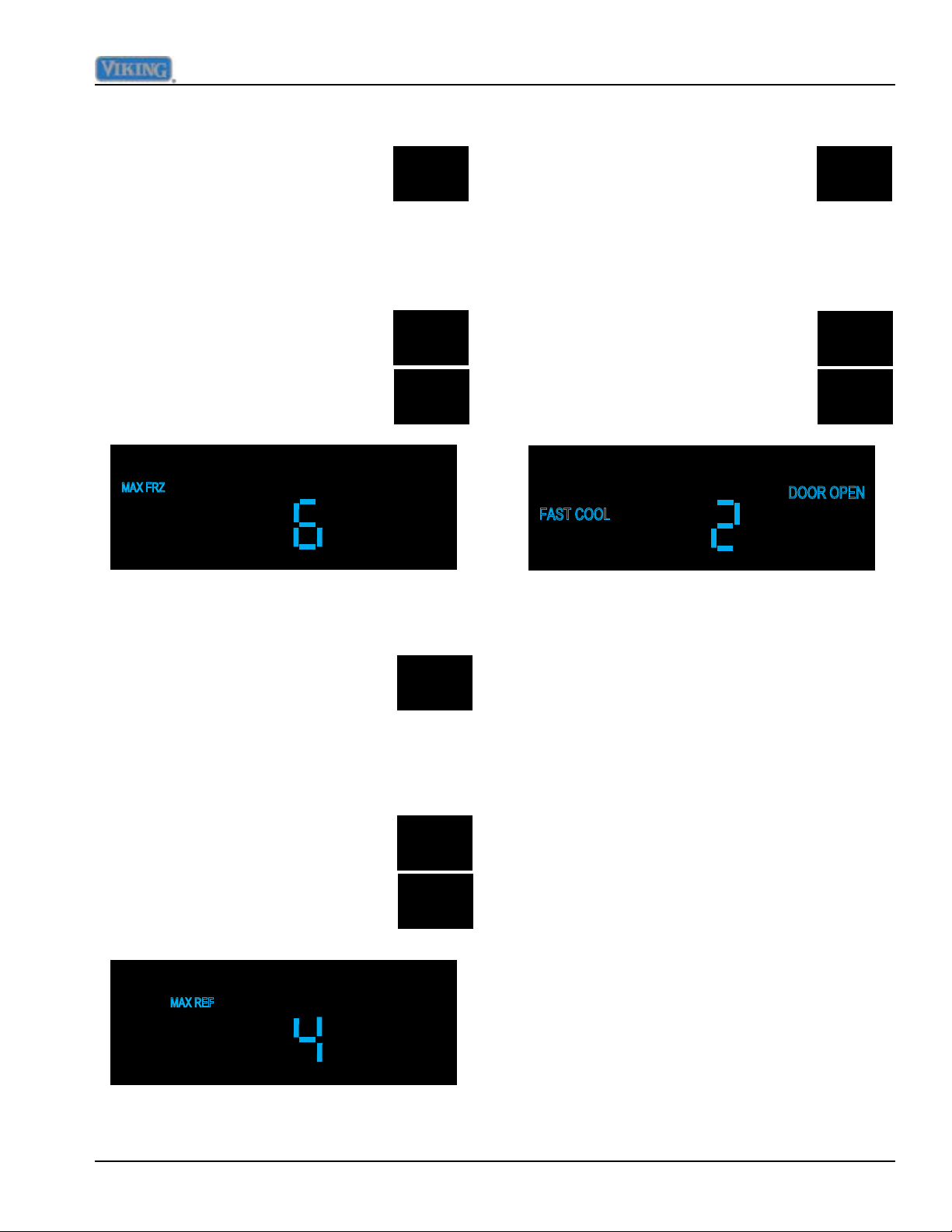
Adjust MAX FRZ duration
While in Mode B, press and
release "MAX FRZ" one time,
MAX
FRZ
this will result in "MAX FRZ"
illuminating on the display along
with the current numeric value in hours that
MAX FRZ is set at. Factory default for this
adjustment is 6 hours. Range is 1 to 20 hours
in 1 hour increments.
HIGHER
The duration is adjusted using the
"HIGHER and LOWER" pads.
LOWER
Adjust FAST COOL duration
While in Mode B, press and
release "FAST COOL" one time,
FAST
COOL
this will result in "FAST COOL"
illuminating on the display along
with the current numeric value in hours that
FAST COOL is set at. Factory default for this
adjustment is 2 hours. Range is 1 to 20 hours
in 1 hour increments.
HIGHER
The duration is adjusted using the
"HIGHER and LOWER" pads.
LOWER
Adjust MAX REF duration
While in Mode B, press and
release "MAX REF" one time,
MAX
REF
this will result in "MAX REF"
illuminating on the display along
with the current numeric value in hours that
MAX REF is set at. Factory default for this
adjustment is 4 hours. Range is 1 to 20 hours
in 1 hour increments.
HIGHER
The duration is adjusted using the
"HIGHER and LOWER" pads.
LOWER
©2012 Viking Preferred Service 35
Page 36
Service Procedures
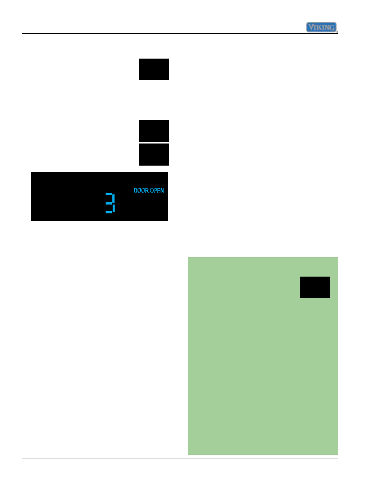
Adjust Door Open Alarm delay
While in Mode B, press and
release "ALARM OFF" one time,
ALARM
OFF
this will result in "DOOR OPEN"
illuminating on the display along
with the current numeric value in minutes that
the delay is set at. Factory default for this
adjustment is 3 minutes. Range is 1 to 20
minutes in 1 minute increments.
HIGHER
The duration is adjusted using the
"HIGHER and LOWER" pads.
LOWER
Adjust DC Fan Cycling On Time
This adjustment is not a field adjustment and
should not be performed by technicians. This
is a factory only adjustment.
If you see "dCo" in the display, immediately
exit Mode B by holding "ACTIVATE
CONTROLS" for three seconds until you get
three audible beeps. Return to your previous
actions.
Adjust DC Fan Cycling Off Time
This adjustment is not a field adjustment and
should not be performed by technicians. This
is a factory only adjustment.
If you see "dCF" in the display, immediately
exit Mode B by holding "ACTIVATE
CONTROLS" for three seconds until you get
three audible beeps. Return to your previous
actions.
Adjust Compressor Dwell Time
This adjustment is not a field adjustment and
should not be performed by technicians. This
is a factory only adjustment.
If you see "Cdt" in the display, immediately
exit Mode B by holding "ACTIVATE
CONTROLS" for three seconds until you get
three audible beeps. Return to your previous
actions.
Adjust Compressor High Frequency
This adjustment is not a field adjustment and
should not be performed by technicians. This
is a factory only adjustment.
If you see "CHF" in the display, immediately
exit Mode B by holding "ACTIVATE
CONTROLS" for three seconds until you get
three audible beeps. Return to your previous
actions.
Exiting Mode B
To exit Mode B and retain any changes
made in system up to this point you
must press and release
"ACTIVATE CONTROLS" one
ACTIVATE
CONTROLS
time, the display changes to
"PrA". This signifies that the changes
were written to the eeprom and that
the system has left Mode B and
returned to Mode A.
The other way to ensure changes
have been written into the eeprom
is to press and hold "ACTIVATE
CONTROLS" for three seconds and
you will get three audible tones along
with a normal temperature display.
This indicates that you have left Mode
B and returned to normal operation.
Failure to do this will cause system
to time out after 10 minutes and any
changes will be lost.
36 ©2012 Viking Preferred Service
Page 37
Program Mode C
Service Procedures
If you are not already in Mode B, go back to
Mode B instructions on Page 34.
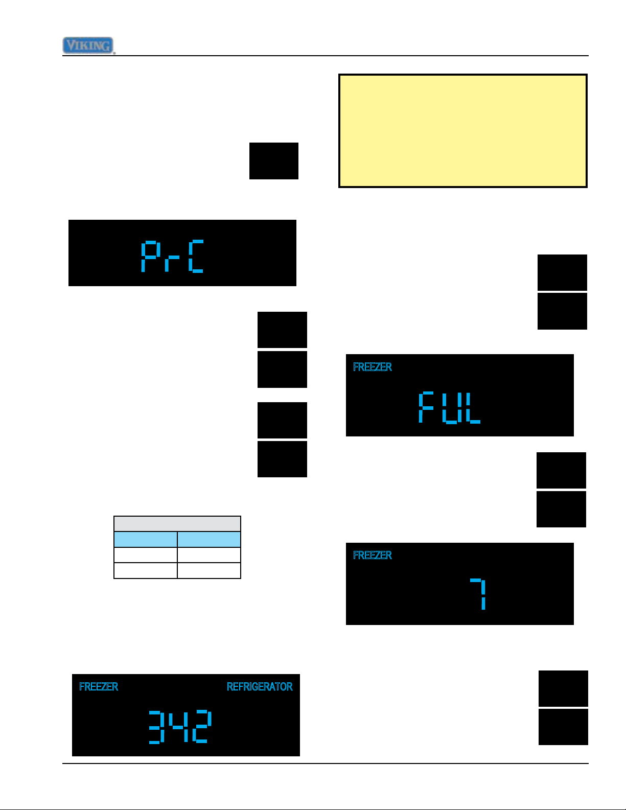
Once you are in Mode B (Prb in
display), press and hold "ALARM
OFF" for three seconds and
ALARM
OFF
display will change to "PrC",
signifying that control is now in Program
Mode C, see illustration below.
Set Model type
While in Mode C, press and
release, either "FRZ TEMP or
FRZ
TEMP
REF TEMP" to display the current
model type setting, a three digit
number in the display.
REF
TEMP
Setting the model code is required
whenever the low voltage board is
replaced, this will update all of the settings
indicated in Table 1 on Page 42 for the
model you select. With this setting you can
program all necessary settings with one
input for the appliance.
Adjust Freezer Upper Temperature Limit
While in Mode C, press and hold
"MAX FRZ" and and then hold the
MAX
FRZ
"HIGHER" pad for three seconds,
this will result in the display
changing to "FUL".
HIGHER
Pressing and releasing either
"HIGHER or LOWER" pads
HIGHER
will allow you to change model
types until you get to the proper
three digit number for your unit,
LOWER
seeTable 1 on Page 42 Set the
correct model code from table
below.
Model code
Model Value
5421 342
5481 348
The "REFRIGERATOR and/or FREEZER"
indicators will illuminate for each model type
as it is selected depending upon the model
configuration. (example: code 430 will only
illuminate the "REFRIGERATOR" indicator
because it is an All Refrigerator)
Pressing and releasing "HIGHER
and LOWER" pads will increase
HIGHER
or decrease the set point, which
o
should be set at 7
F.
LOWER
Adjust Freezer Lower Temperature Limit
While in Mode C, press and hold
"MAX FRZ" and and then hold the
MAX
FRZ
"LOWER" pad for three seconds,
this will result in the display
changing to "FLL".
LOWER
©2012 Viking Preferred Service 37
Page 38
Service Procedures
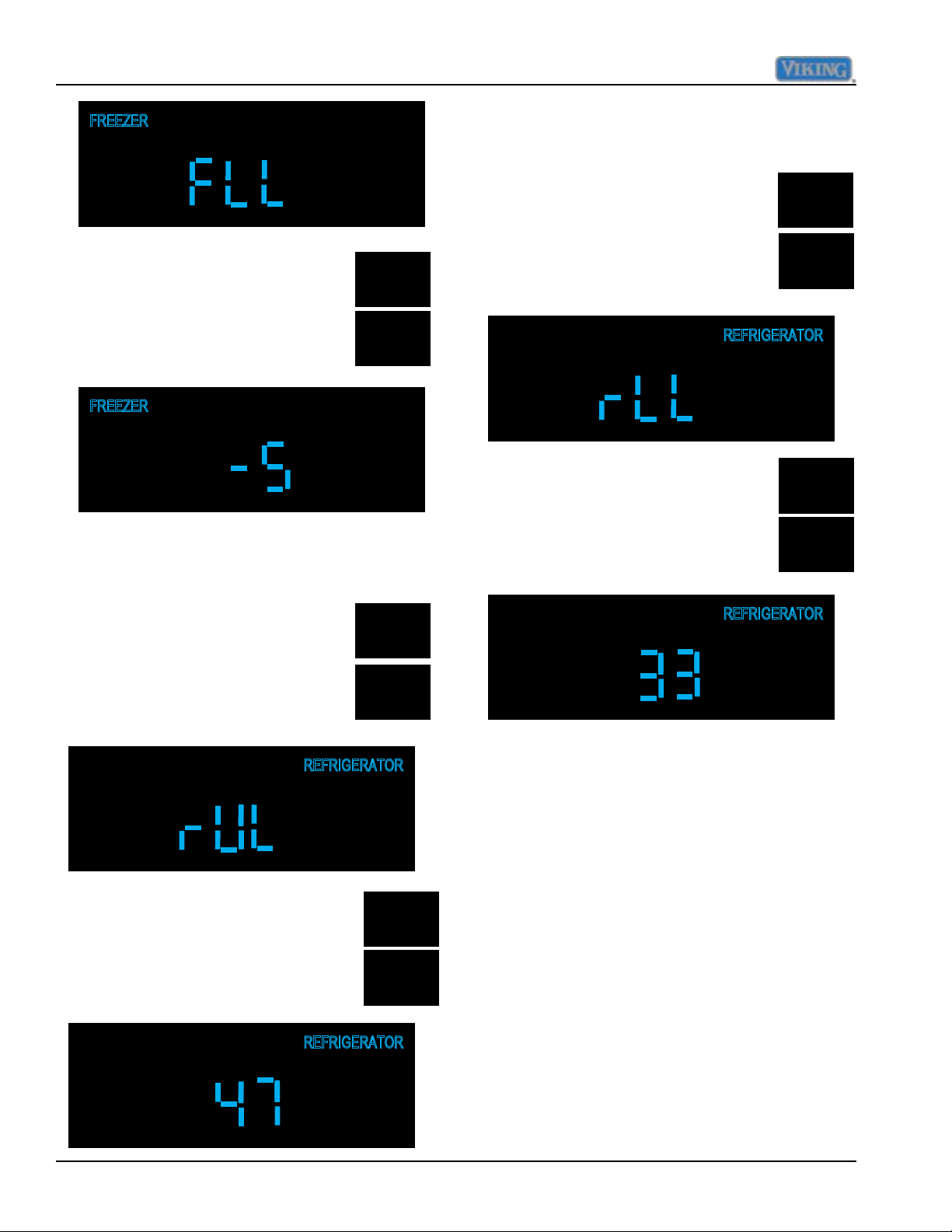
Adjust Refrigerator Lower Temperature
Limit
Pressing and releasing "HIGHER
and LOWER" pads will increase
HIGHER
or decrease the set point, which
o
should be set at -5
F.
LOWER
Adjust Refrigerator Upper Temperature
Limit
While in Mode C, press and hold
"MAX REF" and then press and
MAX
REF
hold the "HIGHER" pad for three
seconds, this will result in the
display changing to "rUL".
HIGHER
While in Mode C, press and hold
"MAX REF" and then press and
hold the "LOWER" pad for three
seconds, this will result in the
display changing to "rLL".
Pressing and releasing "HIGHER
and LOWER" pads will increase
or decrease the set point, which
should be set at 33o F.
MAX
REF
LOWER
HIGHER
LOWER
Defrost lockout adder
This adjustment is not a field adjustment and
should not be performed by technicians. This
is a factory only adjustment.
Pressing and releasing "HIGHER
and LOWER" pads will increase
or decrease the set point, which
o
should be set at 47
F.
HIGHER
LOWER
If you see "dLA" in the display, immediately
exit Mode C by holding "ACTIVATE
CONTROLS" for three seconds until you get
three audible beeps. Return to your previous
actions.
38 ©2012 Viking Preferred Service
Page 39

Defrost start delay
This adjustment is not a field adjustment and
should not be performed by technicians. This
is a factory only adjustment.
If you see "dSd" in the display, immediately
exit Mode C by holding "ACTIVATE
CONTROLS" for three seconds until you get
three audible beeps. Return to your previous
actions.
Defrost termination delay
This adjustment is not a field adjustment and
should not be performed by technicians. This
is a factory only adjustment.
Service Procedures
To exit Mode C and retain any changes
made in system up to this point you
must press and release
"ACTIVATE CONTROLS" one
time, the display changes to
"Prb". This signifies that the
changes were written to the eeprom
and that the system has left Mode C
and returned to Mode B.
The other way to ensure changes
have been written into the eeprom
is to press and hold "ACTIVATE
CONTROLS" for three seconds and
you will get three audible tones along
with a normal temperature display.
This indicates that you have left Mode
C and returned to normal operation.
ACTIVATE
CONTROLS
If you see "dtd" in the display, immediately
exit Mode C by holding "ACTIVATE
CONTROLS" for three seconds until you get
three audible beeps. Return to your previous
actions.
Constant Evaporator fan mode
This mode only applies to All Refrigerator
units and is ignored by any other unit
configuration.
Plant mode
This adjustment is not a field adjustment and
should not be performed by technicians. This
is a factory only adjustment.
Failure to do this will cause system
to time out after 10 minutes and any
changes will be lost.
If you see "Pt" in the display, immediately turn
power switch to OFF. Turn power back on and
start over.
©2012 Viking Preferred Service 39
Page 40
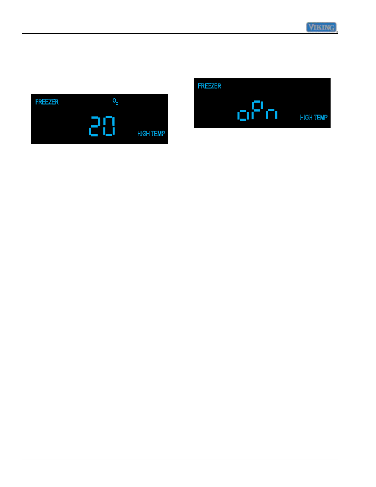
Service Procedures
ALARMS
There are ve alarms that signify faulty conditions,
they will each be covered in detail.
1. High Temp Alarm
Freezer High Temp alarm
When the freezer temperature reaches the high temp
level (15
predetermined time (3 hours), also set in EEPROM,
the "HIGH TEMP" indicator will come on and the
"FREEZER" indicator will flash. You will also get
a continuous audible alarm, consisting of a beep
pattern (ON - 0.5 sec, OFF 2 sec's).
o
F) ,set in the EEPROM at factory, for a
2. Open Thermistor Alarm
The controller will sense an open thermistor condition
within 15 seconds of power on.
Open Refrigerator Thermistor Alarm
When the control senses that the refrigerator
thermistor is open, "oPn" is displayed on the control
along with the zone, "REFRIGERATOR". If the
control was in the Freezer zone when the condition
occurred, it automatically switches over to the faulty
zone ("REFRIGERATOR"). You also receive an
audible alarm consisting of ve beeps that occurs
only one time. The visual alarms as described above
will continue until the condition is corrected.
Refrigerator High Temp alarm
When the freezer temperature reaches the high temp
o
level (50
F) ,set in the EEPROM at factory, for a
predetermined time (3 hours), also set in EEPROM,
the "HIGH TEMP" indicator will come on and the
"REFRIGERATOR" indicator will flash. You will also
get a continuous audible alarm, consisting of a beep
pattern (ON - 0.5 sec, OFF 2 sec's).
If the condition(s) change and the units temperature(s)
are brought back within limits as described above,
the audible alarm will turn off. The "HIGH TEMP"
and the appropriate zone (Refrigerator or Freezer)
indicator will continue to operate as described above.
To cancel the audible alarm when condition rst
occurs, press and release "ALARM OFF", this
will result in shutting off the audible alarm only.
To clear the "HIGH TEMP" and flashing zone light
(FREEZER or REFRIGERATOR), the temperature
must be brought down below the limit temperature
as described in the appropriate zone above. Then
pressing and releasing "ALARM OFF" once will
clear the "HIGH TEMP" off the screen and the zone
indicator will stop flashing.
Open Freezer Thermistor Alarm
When the control senses that the freezer thermistor
is open, "oPn" is displayed on the control along
with the zone, "FREEZER". If the control was in
the Refrigerator zone when the condition occurred,
it automatically switches over to the faulty zone
("FREEZER"). You also receive an audible alarm
consisting of ve beeps that occurs only one time.
The visual alarms as described above will continue
until the condition is corrected.
The unit will continue to execute temperature control
and defrost operations as required until the condition
is corrected. The control does this through software
programming, acting as if the cut-out temperature
is never reached in the faulty zone, temperature
control in the other zone is unaffected.
The visual alarms will reset by themselves within
15 seconds of the open thermistor condition being
corrected and temperature control reverts back to
normal operation.
40 ©2012 Viking Preferred Service
Page 41
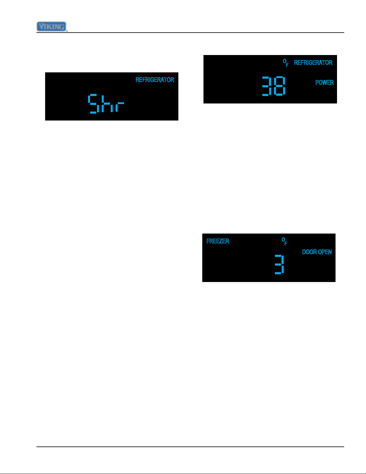
Service Procedures
3. Shorted Thermistor Alarm
The controller will sense a shorted thermistor
condition within 15 seconds of power on.
Shorted Refrigerator Thermistor Alarm
When the control senses that the refrigerator
thermistor is shorted, "Shr" is displayed on the
control along with the zone, "REFRIGERATOR".
If the control was in the Freezer zone when the
condition occurred, it automatically switches over
to the faulty zone ("REFRIGERATOR"). You also
receive an audible alarm consisting of ve beeps
that occurs only one time. The visual alarms as
described above will continue until the condition
4. Power Loss Alarm
If the control experiences a power loss condition
and power is restored, the Power Loss alarm is
displayed. This consists of the "POWER" indicator
being flashed on and off along with the temperature
digits flashing on and off. All other indicators will be
off and only "ACTIVATE CONTROLS and ALARM
OFF keys are active on the control panel.
There is no audible alarm indication associated
with the power loss alarm. Pressing and releasing
the "ALARM OFF" pad will result in "POWER"
indicator extinguishing and the temperature digits
revert back to normal temperature display.
is corrected.
Shorted Freezer Thermistor Alarm
When the control senses that the freezer thermistor
is shorted, "Shr" is displayed on the control along
with the zone, "FREEZER". If the control was in
the Refrigerator zone when the condition occurred,
it automatically switches over to the faulty zone
("FREEZER"). You also receive an audible alarm
consisting of ve beeps that occurs only one time.
The visual alarms as described above will continue
until the condition is corrected.
The unit will continue to execute temperature control
and defrost operations as required until the condition
is corrected. The control does this through software
programming, acting as if the cut-out temperature
is never reached in the faulty zone, temperature
control in the other zone is unaffected.
The visual alarms will reset by themselves within
15 seconds of the open thermistor condition being
corrected and temperature control reverts back to
normal operation.
5. Door Open Alarm
If the control senses that a door is open for a period
of time, equal to the door open delay (factory default
is 3 minutes, this time can be adjusted in service
mode B) a continuous audible alarm will sound.
At the same time "DOOR OPEN" illuminates on
LED display and will remain on until condition is
corrected.
Press the "ALARM OFF" pad and the audible alarm
will cease. Pressing and holding the "ALARM OFF"
pad for three seconds will disable the audible door
alarm, until the "ALARM OFF" pad is again held for
three seconds which will enable the audible door
alarm once again.
These actions will not clear the visual "DOOR"
alarm, that can only be cleared by shutting the
doors and allowing the control to reset it.
©2012 Viking Preferred Service 41
Page 42
Service Procedures
TABLE 1 - Model types
Model
Type
Model
Code
VCC
Freq
Low
HZ
REF
Offset
o
F
FRZ
Offset
o
F
REF
Cut-In
o
F
REF
Cut-
out oF
FRZ
Cut-In
o
F
FRZ
Cut-
out oF
REF
user
default
temp
REF
user
default
temp
BM36 136 65 -9 0 6 -6 7 -8 38 0
SxS42 342 75 -6 -2 6 -6 7 -7 38 0
SxS42D 242 75 -8 4 6 -6 7 -7 38 0
SxS48 348 75 -4 -5 6 -6 7 -7 38 0
SxS48D 248 75 -8 1 6 -6 7 -7 38 0
AF30 530 75 -2 7 -8 38 0
AF36 536 75 1 6 -6 38 0
AR30 430 75 -6 6 -6 38 0
AR36 436 65 -5 6 -6 38 0
42 ©2012 Viking Preferred Service
Page 43
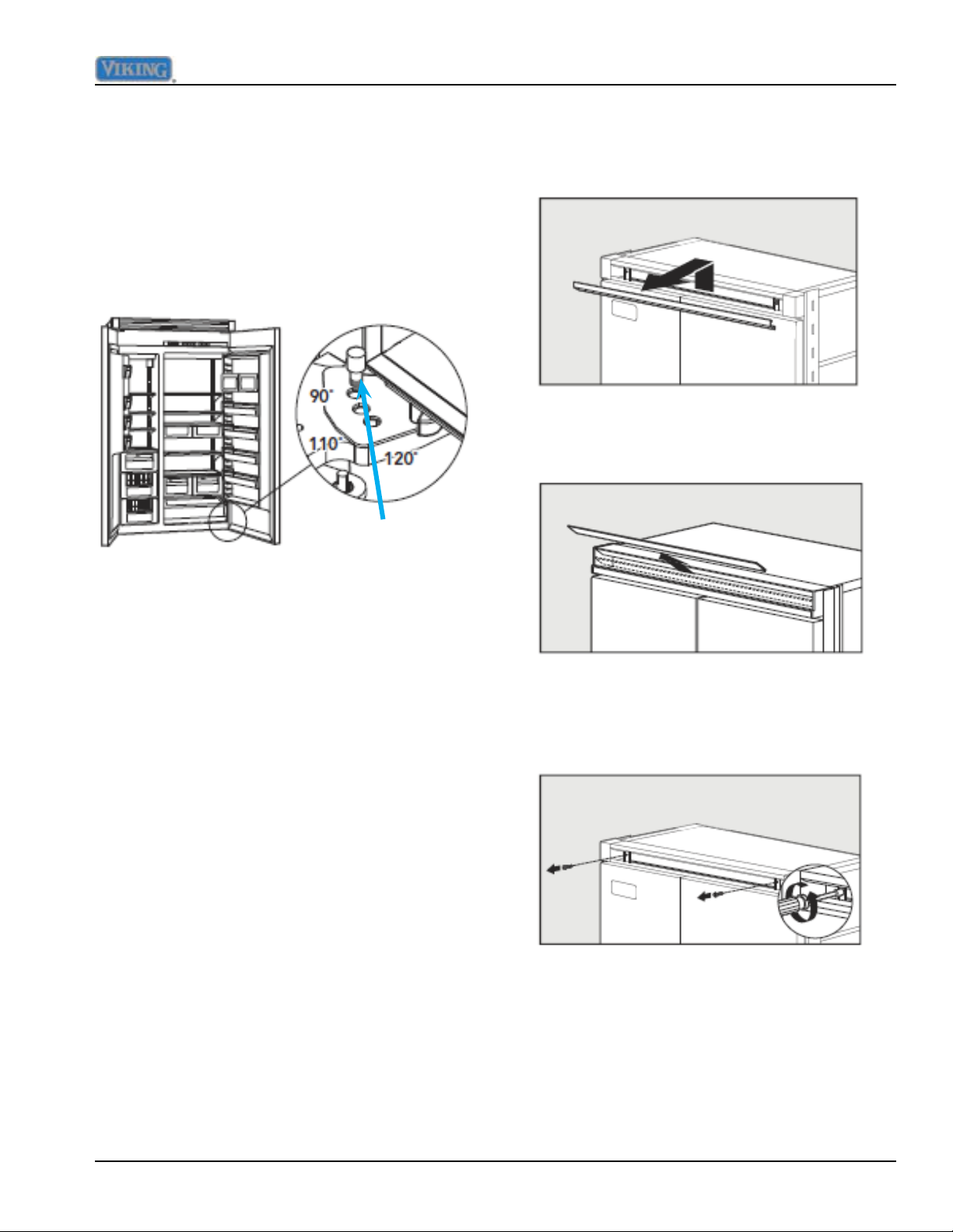
Service Procedures
Door Stop Adjustment
Your refrigerator is factory set at 110° door
stop position. To change to either the 90°
or 120° position, remove the door stop pin
located in the bottom hinge using a 3/16”
allen wrench. For 120° swing, move the pin
to stop hole closest to the unit. For 90° swing,
move pin to stop hole farthest from the unit.
Door stop
pin
To remove upper grill:
1a. (Professional) Lift center grille louver up
and pull out.
1b. (Designer) Pull the center grille louver up
at an angle and pull out.
Light Bulb
Disconnect power at breaker or turn power
disconnect switch to the off position. Lightly
grasp light cover with both hands and pull
down. Replace bulb with an incandescent,
medium base tubular bulb with a maximum
of 40 watts. Replace cover by engaging light
bracket with the back ngers on the light
cover. Once engaged, snap the front ngers
on the light cover.
Note: The clear section of the light cover
is considered the back section. Reconnect
power or turn power disconnect switch to the
“ON” position.
Door Hinge Adjustment
Removal of the upper grill assembly allows
access to door hinge for adjustment.
2. Using an 8” magnetic nut driver, remove
the two 1/4” screws.
©2012 Viking Preferred Service 43
Page 44
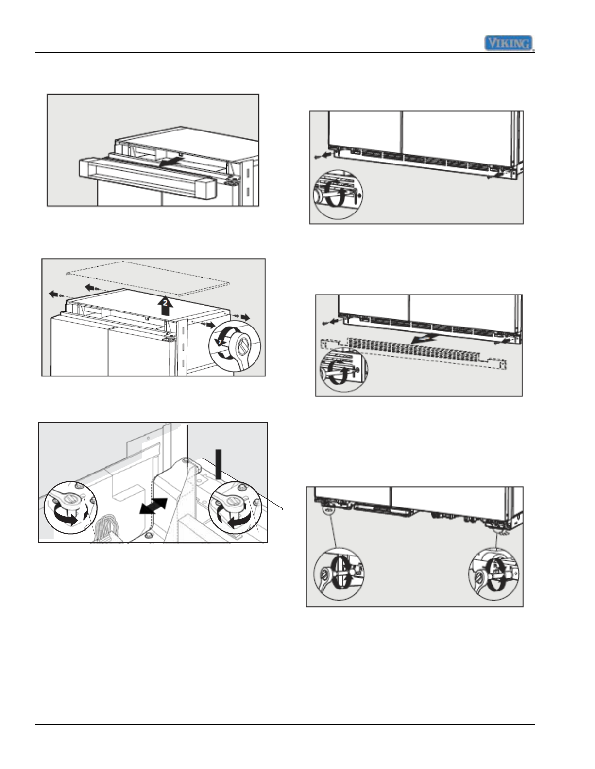
Service Procedures
3. Remove grille assembly.
4. Remove four side screws and remove unit
top.
1. Remove lower kickplate screws using a
Phillips screwdriver.
2. Remove upper kickplate screws using a
Phillips screwdriver. Remove kickplate
assembly.
5. Loosen the four hinge screws. Adjust door.
3. Using a 5/16” head wrench, turn the front
(F) adjustment screws to raise or lower
the front of the refrigerator.
6. Reverse procedure for reinstallation.
Height Adjustment
Removal of the kickplate allows access
to rollers and stabilizing legs for height
adjustment.
Note: DO NOT use an electric device. Over
tightening can cause damage.
44 ©2012 Viking Preferred Service
Page 45
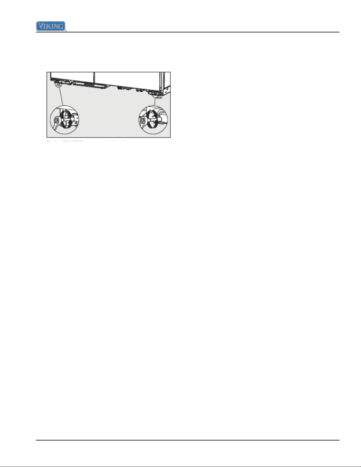
4. Using a 5/16” head wrench, turn the rear
(R) adjustment screws to raise or lower
the rear of the refrigerator.
Note: DO NOT use an electric device.
Overtightening can cause damage.
5. Reinstall kickplate.
Service Procedures
©2012 Viking Preferred Service 45
Page 46
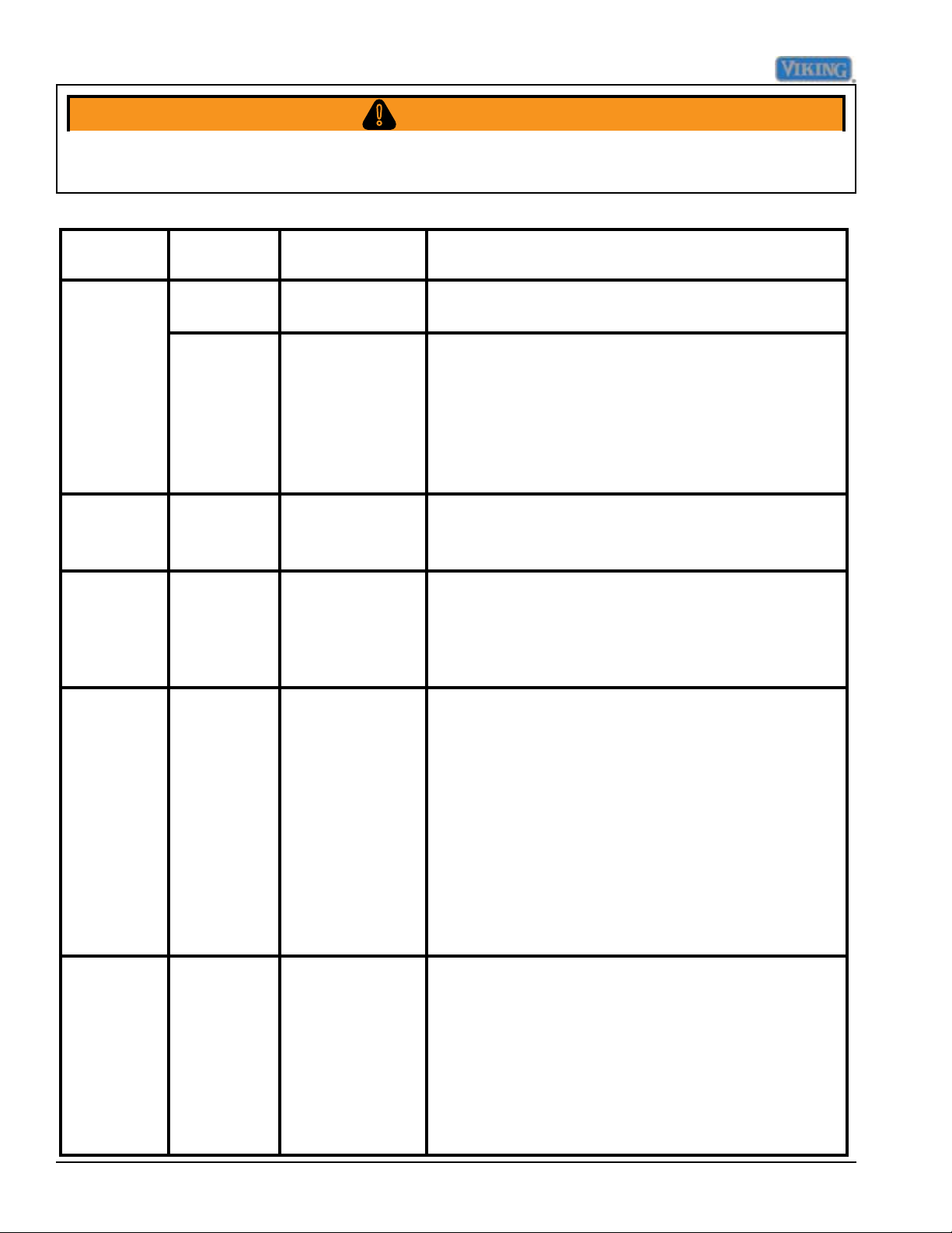
Diagnostics
WARNING!
To avoid risk of electrical shock, personal injury, or death, disconnect electrical power source to unit, unless test
procedures require power to be connected. Discharge capacitor through a resistor before attempting to service.
Ensure all ground wires are connected before certifying unit as repaired and/or operational.
VCC3 Inverter Diagnostic Codes
Code Compressor
Status
1 Flash
(every 15
seconds)
2 Flashes
(every 5 seconds)
3 Flashes
(every 5 seconds)
4 Flashes
(every 5 seconds)
ON 1. No failure
OFF 1. No signal
OFF 1. No signal
OFF 1. Compressor
OFF 1. Compressor
Possible Fault Service Action
• If system is not working properly, check other refrigeration
detected
from control
board
2. Open
Thermistor
from the con trol board
/ inverter cable
open circuit
2. Compressor
winding open
circuit
damaged /
system
damaged
components.
• If refrigerator settings (thermistor conditions) are at levels
in which the compressor should be “ON”.
• Unplug inverter from power supply and wait for 2
minutes, reconnect the inverter to the power supply
and wait for 12 minutes.
• If inverter still shows 1 flash code and compressor is
OFF, then check the control board.
• Check frequency cable connection
• If frequency cable connection is good , replace
inverter.
• Check compressor/inverter cable connection
• Check compressor winding resistances (among the 3
terminal hermetic pins)
• If resistances are within specications and
compressor/inverter cable is OK, replace inverter.
• Check compressor input power
• Check compressor winding resistances
• Check leakage current between hermetic terminal
pins and compressor shell.
• If resistance or leakage current is out of spec, replace
the compressor.
• If resistance and leakage current are within spec,
check inverter/compressor cable for open circuit.
• Unplug inverter from power supply and wait for 2
minutes, reconnect the inverter to the power supply
and wait for 12 minutes.
• If inverter still shows 4 flash code and compressor is
OFF, replace the compressor.
No Flash OFF 1. No input
power
2. Inverter
damaged
46 ©2012 Viking Preferred Service
• Check the input power (115V)
• If there is no signal, check input power connections
• If voltage is within specs, unplug inverter from power
supply and wait for 2 minutes, reconnect the inverter to
the power supply and wait for 12 minutes.
• If inverter still shows no flash code and compressor is
OFF, change the inverter.
• If the inverter shows no flash code and the compressor is
ON, diagnostic function is not working properly.
Page 47
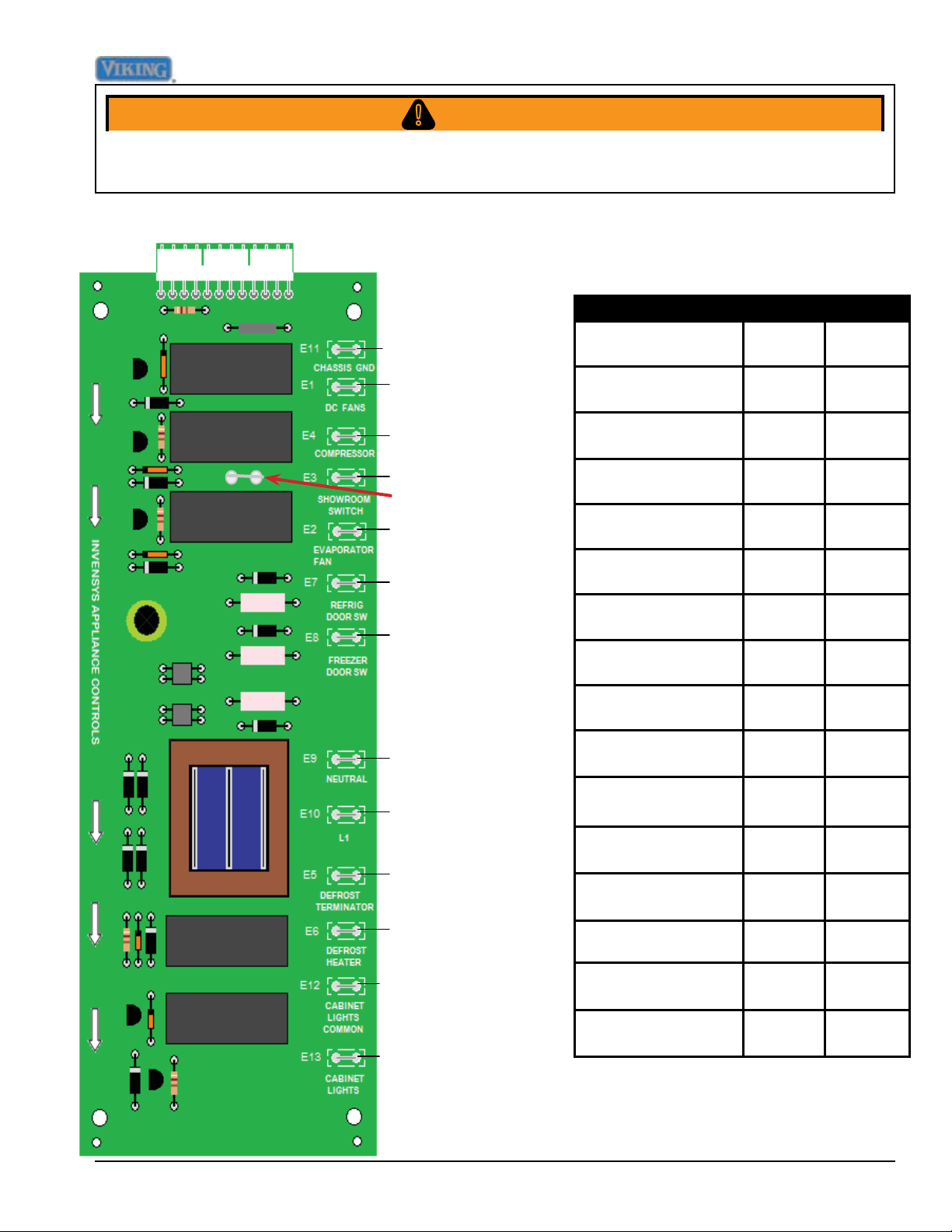
Diagnostics
WARNING!
To avoid risk of electrical shock, personal injury, or death, disconnect electrical power source to unit, unless test
procedures require power to be connected. Discharge capacitor through a resistor before attempting to service.
Ensure all ground wires are connected before certifying unit as repaired and/or operational.
High Voltage Board
High Voltage Board
E11 Ground
E1 Refrigerator/
Condensate Fans
E4 Compressor
Component Test
Point
Refrigerator/Condensate Fans
Evaporator Fans E2-E11 115 VAC
E1-E11 24 VDC
Reading
E14
E3 Line In–120 VAC
E14 Aux Heater
E2 Evaporator Fan
E7 Refrigerator Door
Switch
E8 Freezer Door Switch
E9 Neutral
L1 Line In - 120 VAC
E5 Defrost Terminator
L1 E3-E11 115 VAC
Compressor / Condenser Fan
Defrost Terminator
(closed)
Defrost Terminator
(open)
Defrost Heater E6-E11 115 VAC
Ref door switch (top
right light)
Freezer door switch
(left light)
Neutral In E9-E11 N/A
Line In E10-E11 115 VAC
Ground E11 N/A
E4-E11 115 VAC
E5-E11 0 VAC
E5-E11 115 VAC
E7-E11 115 VAC
E8-E11 115 VAC
E6 Defrost Heater
E12 Neutral in
E13 Light Relay
©2012 Viking Preferred Service 47
Neutral In (lights) E12-E11 N/A
Neutral Out (lights) E13-E11 115 VAC
Aux Heater (Dispenser units only)
E14-E11 115 VAC
Page 48
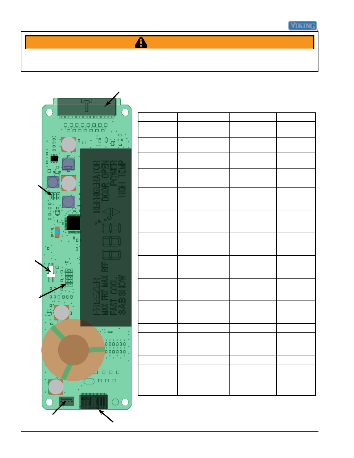
Diagnostics
WARNING!
To avoid risk of electrical shock, personal injury, or death, disconnect electrical power source to unit, unless test
procedures require power to be connected. Discharge capacitor through a resistor before attempting to service.
Ensure all ground wires are connected before certifying unit as repaired and/or operational.
P3
J7
P8
P4
Low Voltage Board
Pin location Function Voltage range Signal
P4-1 Dc supply to
thermistors
P4-2 Freezer thermistor
input
P4-3 Refrigerator
thermistor input
P4-4 Provide zero
timing
P4-5 DC Fan enable 17.8 vdc - 38
P4-6 Defrost
termination
P4-7 Evaporator fan
enable
P4-8 Compressor
enable
P4-9 Defrost termina-
tion signal
P4-10 Door signal 25.8 vdc - 38
P4-11 PS Reference 0 vdc DC
P4-12 -30 vdc 22.8 vdc - 38
P4-13 Not used AC
P4-14 Not used AC
P4-15 Light enable relay 17.8 vdc - 38
4.5 - 5.5 VDC,
ref to P4-12
0 - 5.5 VDC, ref
to P4-12
0 - 5.5 VDC, ref
to P4-12
26 V p-p to 34V
p-p, ref P4-12
vdc, ref to
chassis grnd.
17.8 vdc - 38
vdc, ref to
chassis grnd.
17.8 vdc - 38
vdc, ref to chas-
sis ground
17.8 vdc - 38
vdc, ref to chas-
sis ground
25.8 vdc - 38
vdc, ref to chas-
sis grnd
vdc, ref to chas-
sis grnd
vdc, ref to chas-
sis ground
vdc, ref to chas-
sis ground
DC
DC
DC
See Note 1
below
DC
See Note 2
below
See Note 2
below
See Note 2
below
See Note 2
below
See Note 2
below
See Note 2
below
See Note 2
below
NOTE 1 : Requires an oscilloscope to measure
NOTE 2 :DC voltage- load of meter can affect measurement
P5
48 ©2012 Viking Preferred Service
P9
Page 49
Diagnostics
WARNING!
To avoid risk of electrical shock, personal injury, or death, disconnect electrical power source to unit, unless test
procedures require power to be connected. Discharge capacitor through a resistor before attempting to service.
Ensure all ground wires are connected before certifying unit as repaired and/or operational.
Troubleshooting Guide
Below and on the following page are some general guides should a problem be detected. Please refer to
the test procedures in this manual to determine the defective component.
Problem Probable Cause Correction
Unit will not operate Power supply
Circuit breaker
Power switch
Water overflows defrost pan Unit not level
Float switch
Pan heater
Ice maker will not operate Freezer too warm
Shut off arm
Water valve
Water supply
Refrigerator too warm Door opening
Warm food placed in unit
Control setting
Door seal
Airflow
Refrigerator fan
Refrigerator too cold Temperature setting
Control board
Airflow
Freezer too warm Control setting
Door seal
Dirty condenser
Control board
Verify voltage
Reset breaker
Turn to the “ON” position
Ensure unit is level
Verify operation of float
Verify heater is working
Verify freezer temperature
Verify the arm is in the “ON” position
Verify valve operation
Verify water supply
Minimize door openings
Allow temperatures to stabilize
Move control to medium setting
Verify closure, replace if needed
Ensure airflow is not obstructed
Verify movement/operation of fan
Move control to medium setting
Verify proper operation
Verify airflow is proper
Move control to medium setting
Verify closure, replace if needed
Clean condenser coil
Verify operation
Freezer too cold Temperature setting
Defrost thermostat
Control board
Unit runs continually Control setting
Door seal
Dirty condenser Condenser/evaporator fan Control
board
Freezer thermistor
Frost on evaporator Defrost thermostat
Evaporator fan
Defrost heater
Unit running and no lights Sabbath Mode
Open circuit
©2012 Viking Preferred Service 49
Move to medium setting
Verify thermostat is closing
Verify operation
Move to medium setting
Verify closure, replace if needed
Clean condenser coil
Verify movement/operation of fan
Verify operation
Verify thermistor is not shorted
Verify thermostat is closing
Check connection and possible short open condition
Verify operation of Sabbath Mode
Repair/replace wiring
Page 50
Diagnostics
WARNING!
To avoid risk of electrical shock, personal injury, or death, disconnect electrical power source to unit, unless test
procedures require power to be connected. Discharge capacitor through a resistor before attempting to service.
Ensure all ground wires are connected before certifying unit as repaired and/or operational.
Ice Problems Action
Jammed cubes (small or oversized cubes) Adjust ll level or level ice maker or refrigerator
Hollow cubes Adjust low ll or remove restrictions in supply line
Level ice maker or refrigerator
Remove obstructions to air flow at ll end so it freezes before
thermostat end
Ice build-up on ejector blades Usually caused by hollow cubes
See hollow cubes above
Remove ice maker, thaw out
Cubes falling back into mold during ejection Check if ll cup is displaced and blocking ice
Fix ll cup or replace ice maker
Cubes falling over back of ice maker Check if ll cup is displaced and blocking ice
Fix ll cup or replace ice maker
Power Problems Action
No power to ice maker at connector socket Determine discontinuity by tracing power
No power to water valve Determine discontinuity by tracing power
Water Problems Action
No water to refrigerator Turn on supply
Look for obstructions in supply line or valve
No water to ice maker Look for obstructions in water valve or ll tube
Clogged water valve Clean or replace water valve depending on type
Insufcient water to ice maker
(with correct ll time)
Low water pressure at supply Increase water pressure to 20 – 120 PSI
Low water pressure at water valve Look for restrictions in line
Excessive water pressure Install pressure regulator and set to 60 PSI
Low water ll volume Adjust water ll screw, clear obstructions in supply line or supply
Excessive water ll volume Adjust water ll screw, reduce water pressure, or replace water
Water overflows ll cup Reposition ll-tube in ll cup or remove obstruction in ll cup
Water overflows mold Adjust water ll screw, level ice maker or refrigerator, reduce
Leaky water valve Tighten connections or replace water valve
Temperature Problems Action
Freezer too warm Adjust freezer setting or repair refrigerator
Check for restrictions in supply line and valve, especially saddle
valves
valve, or replace water valve
valve
water pressure, or replace water valve or ice maker
50 ©2012 Viking Preferred Service
Page 51
Diagnostics
WARNING!
To avoid risk of electrical shock, personal injury, or death, disconnect electrical power source to unit, unless test
procedures require power to be connected. Discharge capacitor through a resistor before attempting to service.
Ensure all ground wires are connected before certifying unit as repaired and/or operational.
Ice maker Problems Action
Raised shut-off arm Lower shut-off arm to “ON” position
Broken or bent shut-off arm Repair arm or replace ice maker
Shut-off arm stuck or obstructed Remove obstruction
Ice maker not level Check level of refrigerator rst, then level ice maker
Can’t level ice maker Level refrigerator rst, then try again
Open thermostat (won’t close below 17˚F) Replace thermostat
Closed thermostat (won’t open above 32˚F) Replace thermostat
Thermostat out of calibration Replace thermostat
Heater not staked in mold Replace ice maker
Won’t cycle test with power available Replace ice maker
Won’t eject ice with power available Replace ice maker
©2012 Viking Preferred Service 51
Page 52
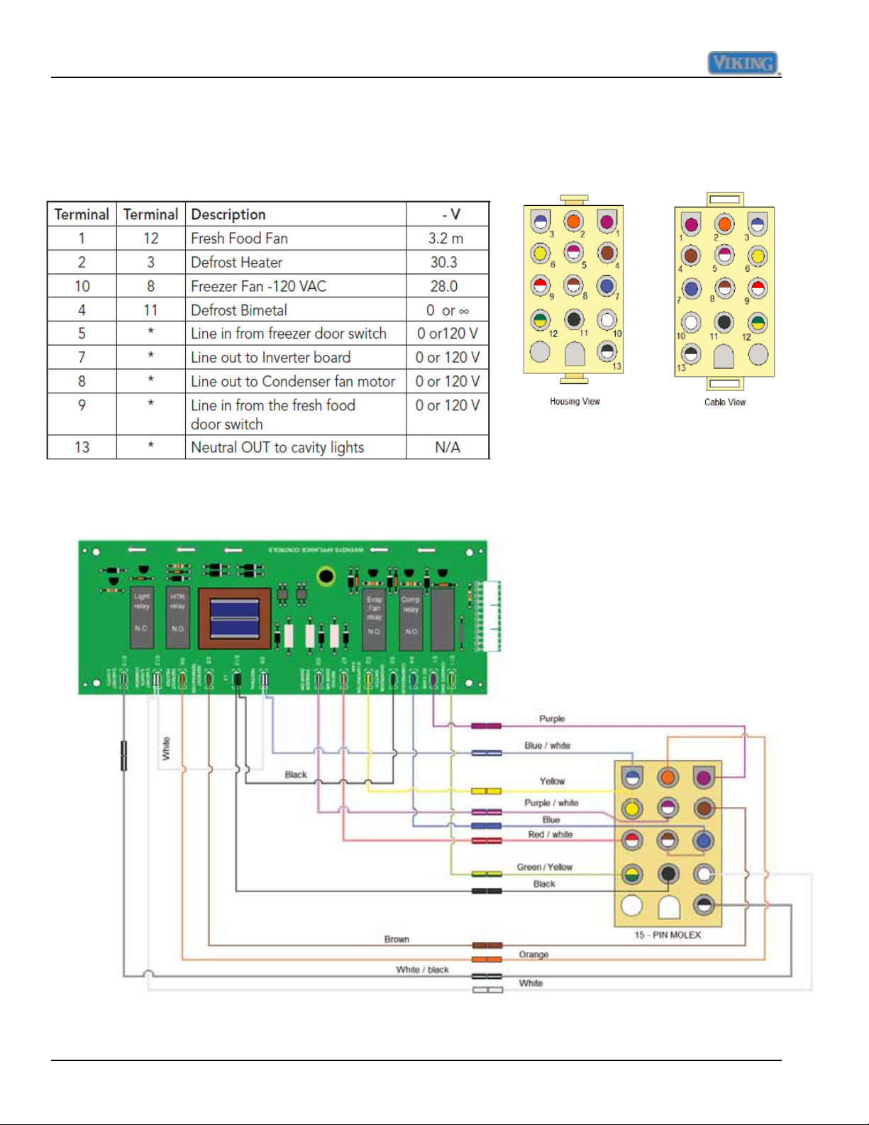
Wiring Diagrams
Wiring and Component Testing
High Voltage Board
Chart for cable view layout
52 ©2012 Viking Preferred Service
Page 53
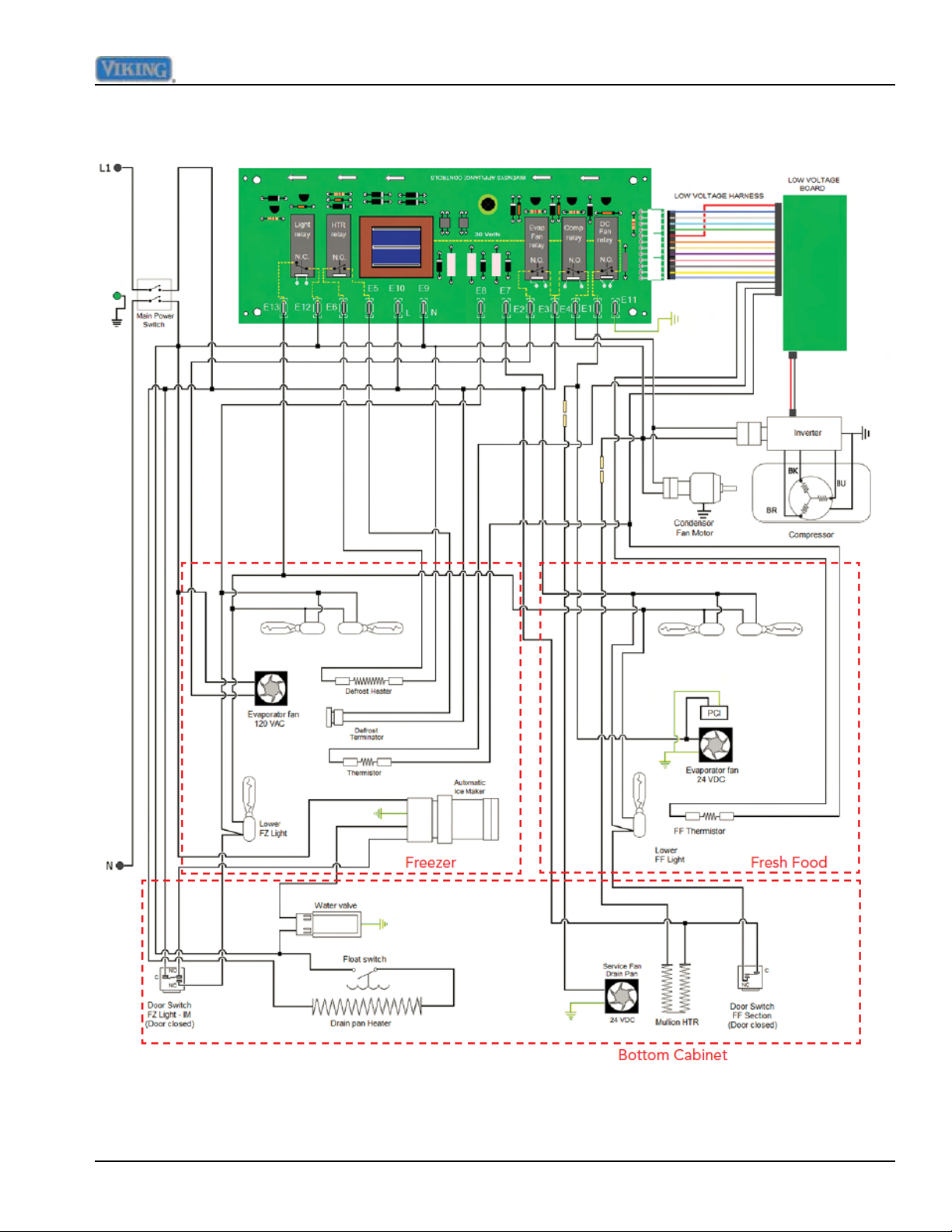
Side by Side schematic
Wiring Diagrams
©2012 Viking Preferred Service 53
Page 54
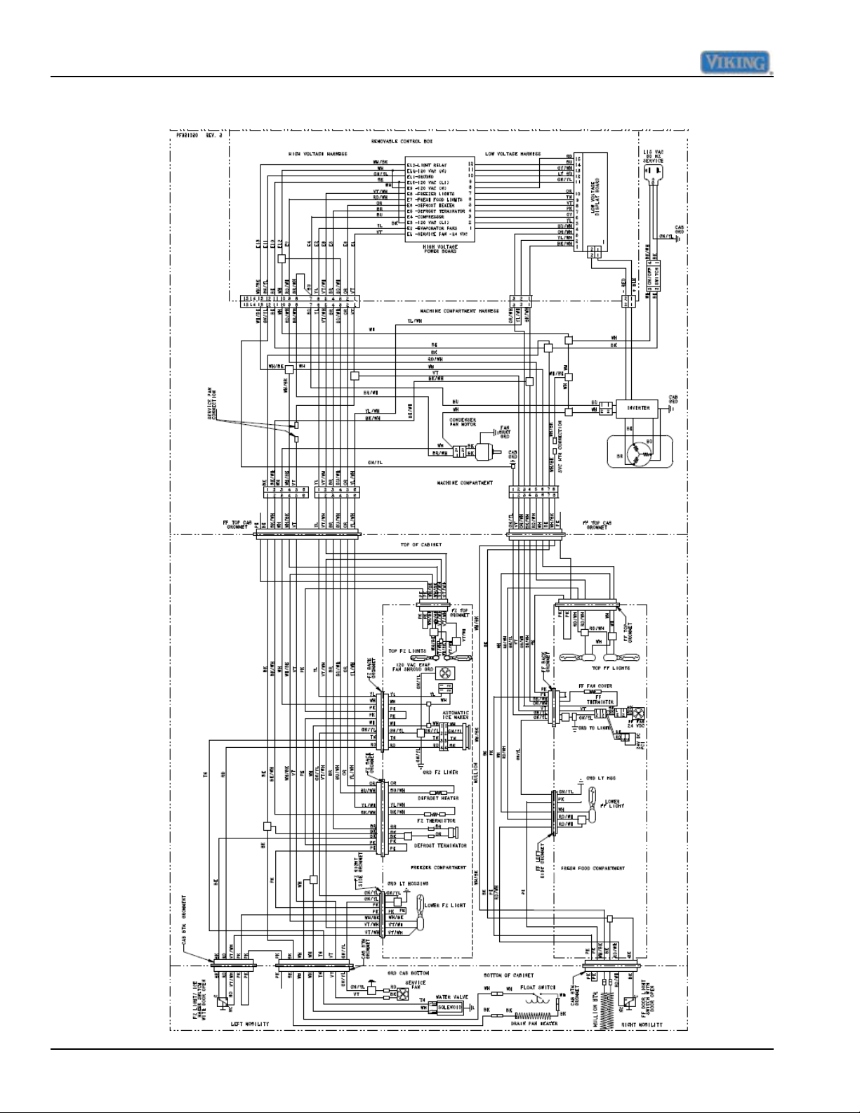
Wiring Diagrams
Side by Side Wiring Diagram
54 ©2012 Viking Preferred Service
 Loading...