

Viking VDSC305, VDSC365, VDSC485, VESC305 Service Manual
Preferred Service
Service
Manual
This manual is to be used by qualified appliance technicians only. Viking
does not assume any responsibility for property damage or personal
injury for improper service procedures done by an unqualified person.
30 • 36 • 48 Inch
Dual Fuel range
All electric range
This Base Manual covers general and
specific information including, but not
limited to the following models
VDSC305
VDSC365
VDSC485
VESC305
VESC305

TABLE OF CONTENTS
VDSC305 – VDSC365 – VDSC 485
VESC305 – VESC306
COMPONENTS AND FUNCTIONAL PARTS:
Control / Timer -------------------------------------------------------------------------------------------- 4
Auto Reset Switch (Thermostat ) -------------------------------------------------------------------- 4
High Limit Switch----------------------------------------------------------------------------------------- 5
Cooling Fan Limit Switch ------------------------------------------------------------------------------ 5
Selector Switch ------------------------------------------------------------------------------------------- 5
Oven Thermostat ------------------------------------------ -------------------------- -------------------- 5
Door Lock Assembly ------------------------------------------------------------------------------------ 6
Relay #1 --------------------------------------------------------------------------------------------------- 6
Relay #2 and #3 ----------------------------------------------------------------------------------------- 6
Convection Fan ------------------------------------------------------------------ ------------------------ 7
Cooling Fan ----------------------------------------------------------------------------------------------- 7
Oven Light Assembly ----------------------------------------------------------------------------------- 7
Voltage and Resistance checks (Self Clean Timer)-------------------------------------------- 8
Voltage and Resistance checks (Heating elements)-------------------------------------------- 9
Selector Switch Contacts ------------------------------------------------------------------------------ 10
WIRING DIAGRAMS
Bake --------------------------------------------------------------------------------------------------------- 11
Convection Bake ----------------------------------------------------------------------------------------- 12
Convection Cook ----------------------------------------------------------------------------------------- 13
Mini Broil ---------------------------------------------------------------------------------------------------- 14
Maxi Broil ---------------------------------------------------------------------- ----------------------------- 15
Convection Broil ------------------------------------------------------------------------------------------ 16
SELF CLEAN
Self Clean (initiate door lock ) ------------------------------------------------------------------------ 17
Clean (door lock below 575* ) ---------------------------------- --------------------------------------- 18
Clean (door lock above 575* ) ------------------------------------------------------------------------- 19
Clean Finished (door lock above 575* ) ------------------------------------------------------------ 20
Clean Finished (door lock below 575* ) ------------------------------------------------------------ 21
Clean Finished (door unlocked ) -------------------------------------------------------------- ------ 21A
ELECTRICAL CONNECTIONS
3 wire or 4-wire wall plug ------------------------------------------------------------------------------------ 22
Hard wire connection ----------------------------------------------------------------------------------------- 23
SERVICE
Disassembly – Component location-------------------------------------------------------------- 24 - 26
Procedures to unlock door with door motor failure -------------------------------------------- 27
VESC Top removal ------------------------------------------------------------------------------------- 28
VESC Voltage / Resistance / Current checks ---------------------------------------------------- 29
VDSC COMPONENTS
(
WITH COLOR CODED WIRES)
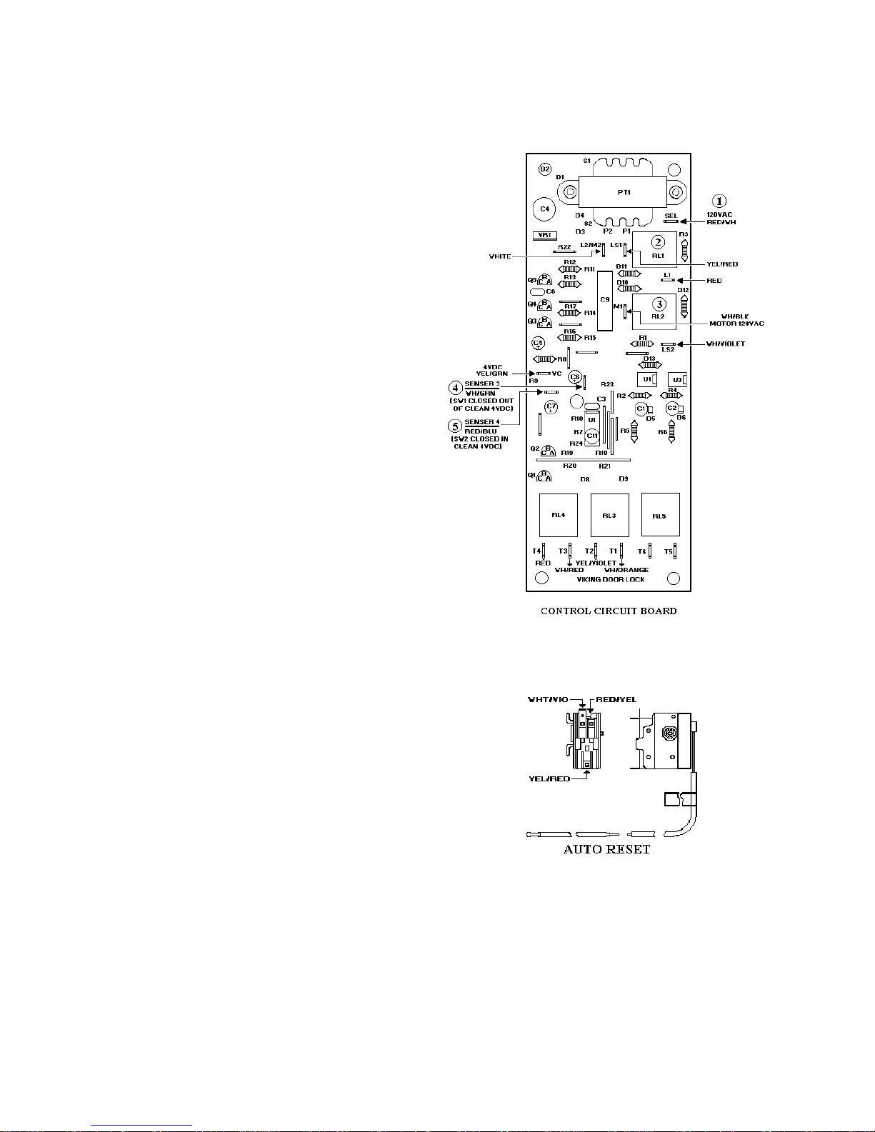
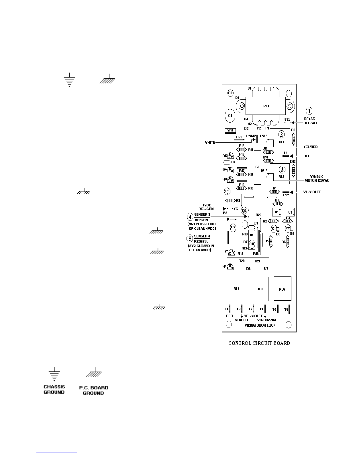
DOOR LOCK CONTROL / TIMER
Function: The Door Lock Control / Timer is
activated by the line voltage at the “ SEL”
( 1 ) contact. Relay “ RL1" ( 2 ) and “RL2"
( 3 ) close providing voltage to the Door Lock
Motor. The Relays stay closed until 10
seconds after sensor #3 ( 4 ) receives a signal
that the Door Lock is fully closed. Once this
happens Relay “RL2" ( 3 ) opens to stop the
Door Lock Motor. Relay “RL1" ( 1 ) stays
closed providing voltage to the Auto Reset
thermostat. Relays “RL3" and “RL4" close
powering the Cooling Fan Motor and Cycle
Relay. “RL3" and “RL4" will stay closed for
3 ½ hours unless power is interrupted to
sensor #3 ( 4 ) or SEL ( 1 ). In which case
“RL3" and “RL4" will open, interrupting the
clean cycle and Cooling Fan, and “RL2" ( 3 )
will close, opening the Door Lock. “RL2" ( 3)
will stay closed until 2 seconds after sensor
# 4 ( 5 ) is powered.
AUTO RESET SWITCH
Function: The Auto Reset Switch is a single
pole / double throw switch ( thermostat )
which is activated by a thermobulb and lever
which is calibrated to 575* F plus / minus 25*
F. Clean door lock below 575* F. The Door
Lock Motor is energized through the Auto
Reset Switch ( thermostat ) contacts 2 - 1.
Clean door lock above 575* F. Auto Reset
Switch ( thermostat ) switches to contacts 1 -3
turning on the Door Lock indicator Light and
disables the Door Lock Motor circuit. Final
below 575* F. Auto Reset Switch
( thermostat ) switches to contacts 1 -2,
turning off the Door Lock Motor circuit
through door Lock Motor / Timer Relay LS2 M1. Door Lock Motor operates until 2
seconds after sensor 4 is signaled by VC that
the Door Lock switch SW1 has been closed
mechanically by the door lock bolt. The Door
Lock / Timer switches LS2 - M1 and LS1-L1
open and the timer resets.
4
VDSC COMPONENTS ( Con’t )
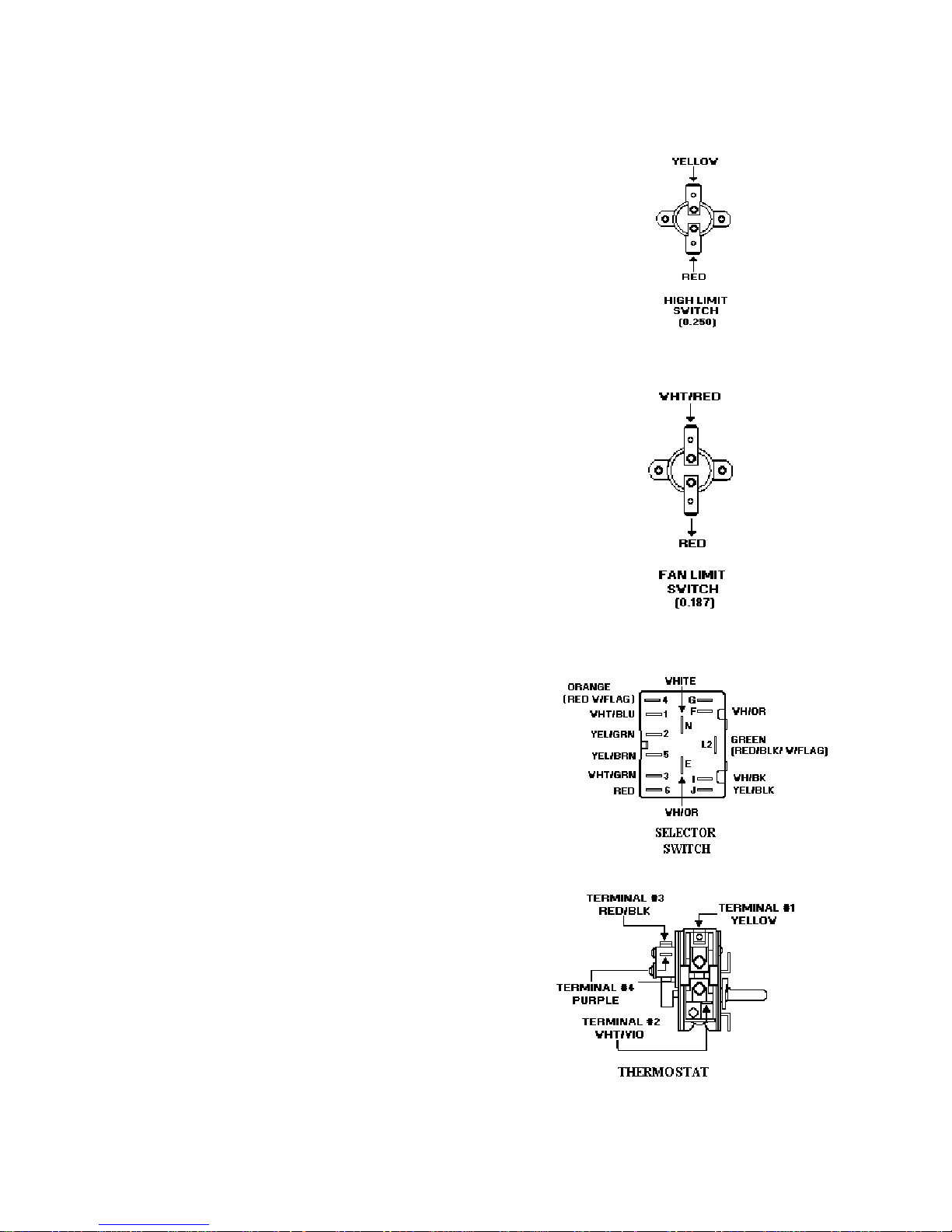
HIGH LIMIT SWITCH
Function: The Switch has a ½ “ bi-metal
disc. The two metals have different thermal
coefficients of expansion which cause the
disc to bow as it heats up. When it reaches
the calibration temperature the disc snaps
open, which opens the electrical contacts.
The Switch opens when temperature reaches
275* F plus or minus 9*F and will close
when temperatures are 248* F plus or minus
9*F.
COOLING FAN LIMIT SWITCH
Function: The Switch has a ½ “ bi-metal disc.
The two metals have different thermal
coefficients of expansion which cause the disc
to bow as it heats up. When it reaches the
calibration temperature the disc snaps closed,
which closes the electrical contacts. The
Switch closes when temperatures reach 230*
F plus or minus 9* F and will open when
temperatures are below 203* F plus or minus
9*F.
SELECTOR SWITCH
Function: Rotating the shaft twists a cam
which moves one or more spring loaded
levers, which make contact with a terminal
closing the circuit.
OVEN THERMOSTAT
Function: As the shaft is rotated from the
OFF position clockwise, an internal cam
pushes a lever, which increases the
temperature at which the thermostat cycles.
Rotating the shaft 212* (angle *) switches an
external (clean) Micro Switch to the closed
position.
5
VDSC COMPONENTS ( Con’t)
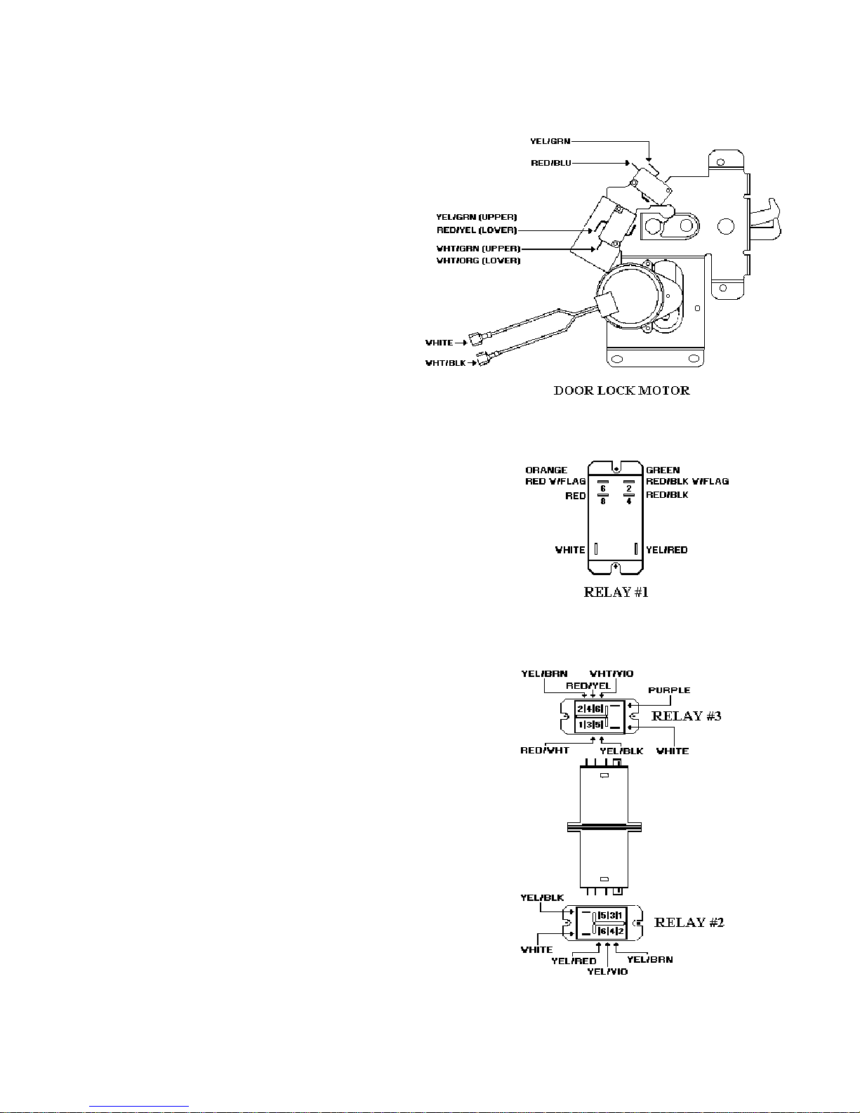
DOOR LOCK
Function: When the Door Lock Motor is
powered it turned a cam which pulls back a
lever. As the lever moves back it allows a
micro switch (SW1) to open. When the lever
reaches the fully closed position it closes a
double stacked micro switch (SW2 & SW3).
Door lock switch SW2 completes the circuit
to sensor #3 on the Door Lock Control/timer
board. After 10 seconds LS1-M1 opens,
stopping the Door Lock motion. Door Lock
Switch #3 closes T1-T2 and T3-T4 energizing
Power Relay #1 and the Cooling Fan. Closing
Power Relay contacts supplies 240 VAC to
both Broil Elements and 120 VAC to the
Bake Element.
POWER RELAY #1
Function: Relay #1 ( power ) supplies power
to the Bake and Broil Elements.
RELAY #2 and RELAY #3
Function: Setting the selector switch to clean
closes the Heating Element circuits 4-F, 1-N,
2-L2, 3-L2 and Door Lock Module / Timer
circuit J-6, energizing Relay #2.The
thermostat cycling contacts 1 to 2 and the
clean switch contacts 3 to 4 close energizing
Relay #3. Relay #3 allows circuit J-6 to turn
on the Clean Indicator Light and enable the
Door Lock Module / Timer to close Relays
LS1-L1 and LS2 - M1. This powers the Door
Lock Motor until 10 seconds after Sensor 3 is
signaled by VC that Door Lock Switch SW2
has been closed mechanically (along with
SW3) by the Door Lock Bolt.
6
VDSC COMPONENTS ( Con’t )
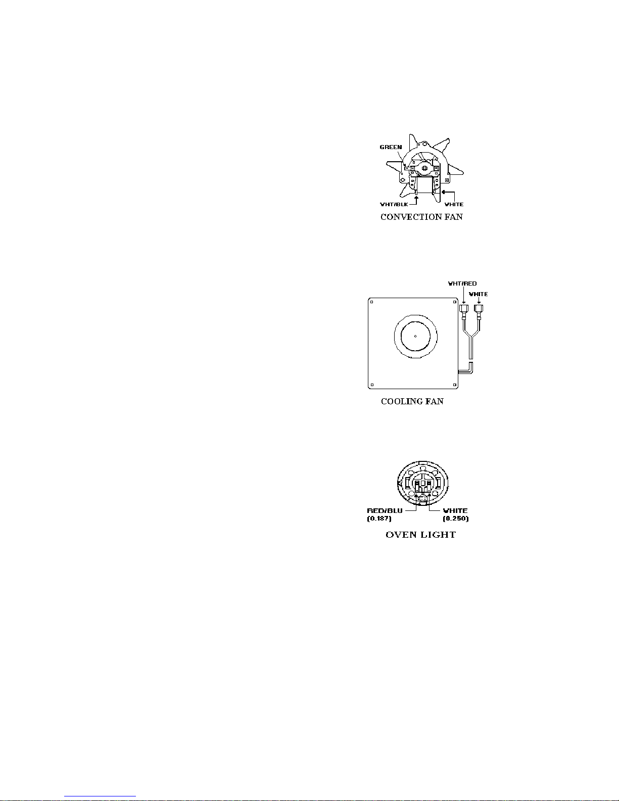
CONVECTION FAN MOTOR
Function: Provides an even flow of air in the
oven cavity for more even baking.
COOLING FAN MOTOR
Function: Provides a continuous supply of
cool air during self clean cycles to keep the
Door Lock Motor and associated circuits cool.
OVEN LIGHT
Function: Provides interior oven light for
viewing baking products.
7
VOLTAGE READINGS
MEASURED WITH DOOR OPEN
T4 107VAC 70VAC
T3 4VAC 16VAC
T2 4VAC 16VAC
T1 5VAC 1VAC
MEASURED WITH DOOR LOCKED
T4 80VAC 56VAC
T3 85VAC 56VAC
T2 90VAC 56VAC
T1 93VAC 56VAC
VC--4VDC
SENSOR 3--3VDC SW2 closed in self clean
(Locked).
SENSOR 4--4VDC SW1 closed with clean
lock open.
M1--120VAC lock motor supply voltage.
(31VAC in locked position)
LS2--70VAC (unlocked)--55VAC (locked)
L1-- 70VAC (unlocked)--56VAC (locked)
L2/M2--16VAC (unlocked)--32VAC
(locked)
LS1--107VAC (locked or unlocked)
SEL--120VAC SUPPLY
8

VOLTAGE and RESISTANCE READINGS
BAKE ELEMENT:
“A” to “B” 21.1 Ohms
“A” to “B” 240VAC during Bake and
Convection Bake.
BROIL ELEMENT:
“A” to “D” ( outside element ) 32.6 Ohms
“A” to “D” 50VAC during Bake and
Convection Bake.
240VAC during Maxi Broil.
240VAC during Convection Broil
240VAC during Self-clean
“B” to “C” ( inside element ) 45.2 Ohms
“B” to “C” 70VAC during Bake and Convection
Bake.
240VAC during Mini Broil
240VAC during Maxi Broil
240VAC during Convection Broil
240VAC during Self-clean
CONVECTION ELEMENT:
“A” to “B” 26 Ohms
“A” to “B” 240VAC during Convection Cook
9
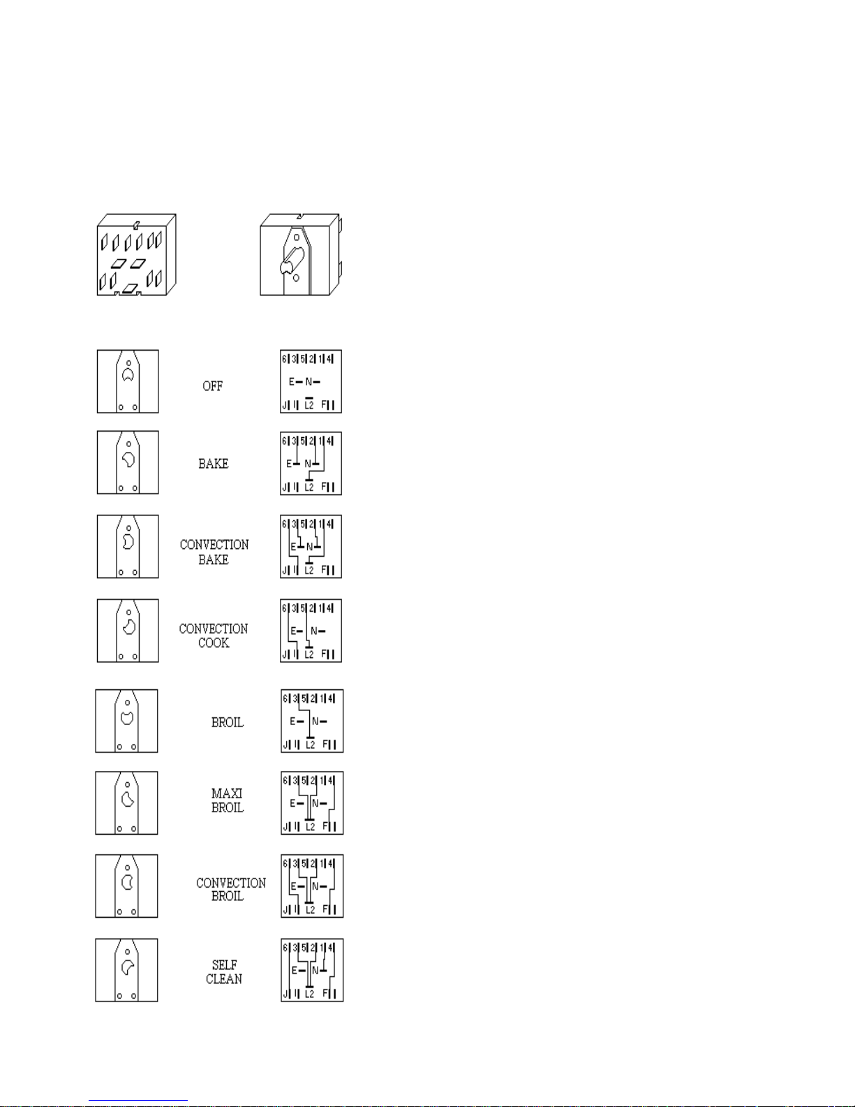
8 POSITION SELECTOR SWITCH
(With shaft position and internal connections
SELF CLEAN
Selector Switch closes Heating Element contacts
4-F, 1-N, 2-L2, 3-L2, and Door Lock Module
/Timer contacts J-6 energizing Relay #1.
Thermostat Clean Position closes Thermostat
cycling contacts 1-2 and normally open (N) common (C) energizing Relay #3.
Relay # 3 turns on the Clean indicator Light and
energizes Door Lock Module / Timer (PC Board)
relays LS1-L1 and LS2-M1, also supplying
120VAC to SEL on the PC board
Relays LS1 and LS2 turns the Door Lock Motor
on through the Auto Reset Thermostat contacts
2-1.
Door Lock Motor rotates opening SW1 and
closing SW2 and SW3.
Door Lock Switch #2 completes the circuit to
sensor #3 on the PC board. After 10 seconds
LS1-M1 opens, stopping the Door Lock motion.
Door Lock Switch #3 closes T1-T2 and T3-T4
energizing Power Relay #1 and the Cooling Fan
.Closing Power Relay #1's contacts supplies
240VAC to both Broil Elements and 120VAC to
the Bake Element.
CLEAN DOOR LOCK ABOVE 575*F
+/-25*F
Auto Reset Thermostat switches to contacts 1-3
turning on the Door Lock indicator Light and
disables the Door Lock Motor circuit.
CLEAN TEMPERATURE (875*F)
REACHED.
Door Lock Module / Timer opens T3 -T-4 and
T1-T2 turning off the Cooling Fan, now powered
by the Fan Limit Switch when needed, and opens
the circuit to the Power Relay #1 disabling the
Heating Elements.
FINAL BELOW 575*F +/-25*F
Auto Reset Thermostat switches to contacts 1-
2, turning off the Door Lock Motor circuit
through Door Lock Motor / Timer Relay LS2-M-
1. Door Lock Motor operates until 2 seconds
after sensor 4 is signaled by VC that the Door
Lock /Timer switches LS2- M1 and LS1-L1 open
and the Timer resets.
10
 Loading...