

Viking VDD5480SS Installation Manual
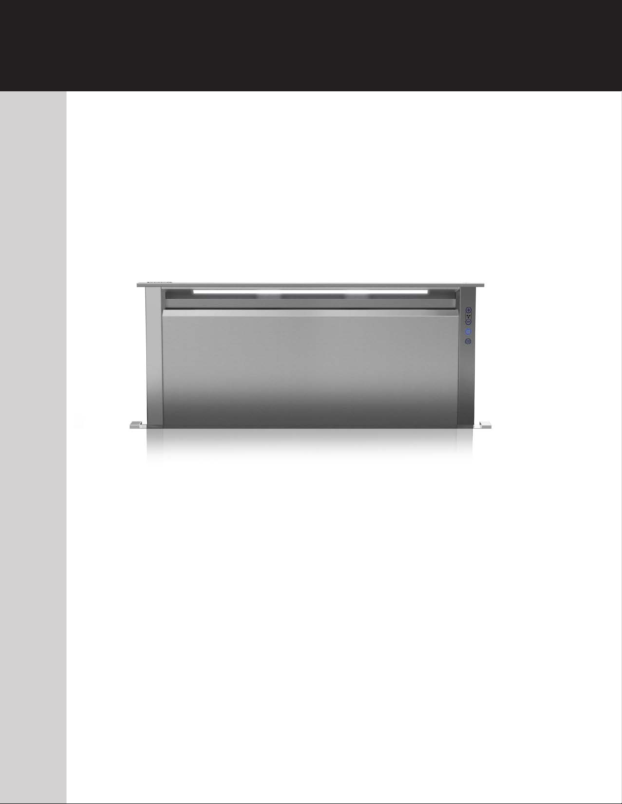
USE / INSTALLATION GUIDE
5 Series
Rear Downdraft Ventilators
MODEL WIDTH BLOWER (purchased separately)
VDD5300/CVDD5300 30" W. VDVI600 Interior or VDVE900 Exterior
VDD5360/CVDD5360 36" W. VDVI600 Interior or VDVE900 Exterior
VDD5450/CVDD5450 45" W. VDVI600 Interior or VDVE900 Exterior, VDVE1200 Exterior
VDD5480/CVDD5480 48" W. VDVI600 Interior or VDVE900 Exterior, VDVE1200 Exterior
READ AND SAVE THESE INSTRUCTIONS
WARNING
TO REDUCE THE RISK OF FIRE, ELECTRIC SHOCK, OR INJURY
TO PERSONS, OBSERVE THE FOLLOWING:
1. Use this unit only in the manner intended by the manufacturer.
If you have questions, contact the manufacturer at the address
or telephone number in the warranty.
2. Before servicing or cleaning unit, switch power off at service
panel and lock the service disconnecting means to prevent
power from being switched on accidentally. When the service
disconnecting means cannot be locked, securely fasten a
prominent warning device, such as a tag, to the service panel.
3. Installation work and electrical wiring must be done by a
qualified person(s) in accordance with all applicable codes
and standards, including fire-rated construction codes and
standards.
4. Sufficient air is needed for proper combustion and exhausting
of gases through the flue (chimney) of fuel burning equipment
to prevent backdrafting. Follow the heating equipment
manufacturer’s guideline and safety standards such as those
published by the National Fire Protection Association (NFPA),
and the American Society for Heating, Refrigeration and
Air Conditioning Engineers (ASHRAE), and the local code
authorities.
5. When cutting or drilling into wall or ceiling, do not damage
electrical wiring and other hidden utilities.
6. Ducted fans must always be vented to the outdoors.
7. To reduce the risk of fire, use only metal ductwork.
8. Do not install this product with the activating switch directly
behind a burner or element. Minimum distance between the
switch and the edge of the burner should be 4 inches.
9. Loose-fitting or hanging clothing should never be worn when
operating this appliance. They may be ignited by burners/
elements on cooktop.
10. Children should not be left alone or unattended in the area
where this appliance is in use.
11. This unit must be grounded.
TO REDUCE THE RISK OF A RANGE TOP GREASE FIRE:
a) Never leave surface units unattended at high settings.
Boilovers cause smoking and greasy spillovers that may
ignite. Heat oils slowly on low or medium settings.
b) Always turn hood ON when cooking at high heat or when
cooking flaming foods.
c) Clean ventilating fans frequently. Grease should not be
allowed to accumulate on fan or filter.
d) Use proper pan size. Always use cookware appropriate
for the size of the surface element.
WARNING
TO REDUCE THE RISK OF INJURY TO PERSONS IN THE EVENT
OF A RANGE TOP GREASE FIRE, OBSERVE THE FOLLOWING
1. SMOTHER FLAMES with a close-fitting lid, cookie sheet, or
metal tray, then turn off the burner. BE CAREFUL TO
PREVENT BURNS. If the flames do not go out immedi-
ately, EVACUATE AND CALL THE FIRE DEPARTMENT.
2. NEVER PICK UP A FLAMING PAN - You may be burned.
3. DO NOT USE WATER, including wet dishcloths or towels - a
violent steam explosion will result.
4. Use an extinguisher ONLY if:
A. You know you have a Class ABC extinguisher, and you
already know how to operate it.
B. The fire is small and contained in the area where it
started.
C. The fire department is being called.
D. You can fight the fire with your back to an exit.
a
Based on “Kitchen Firesafety Tips” published by NFPA.
a
:
CAUTION
1. For indoor use only.
2. For general ventilating use only. Do not use to exhaust
hazardous or explosive materials and vapors.
3. To avoid motor bearing damage and noisy and/or unbalanced
impellers, keep drywall spray, construction dust, etc. off power
unit.
4. Clean filters and grease-laden surfaces frequently.
5. Do not repair or replace any part of this appliance unless
specifically recommended in this manual. All other servicing
should be done by a qualified technician.
6. Please read specification label on product for further
information and requirements.
7. To reduce the risk of fire and electric shock, install this downdraft
only with blower models shown below. Other blower models
cannot be substituted. (Blowers sold separately).
Flex Blower Model VDVI600
Exterior Blower Models VDVE900, VDVE1200
INSTALLER:
Save this manual for Electrical Inspector
and Homeowner to use.
2
CONTENTS
These parts are included with your downdraft housing:
1 - Parts Bag containing:
2 - 2-in. Support Legs
2 - 4-in. Support Legs2 - Screws, 1/4-20 x .50 Hex Head
2 - Screws, 1/4-20 x .50 Hex Head
2 - Screws, #8-18 x .375 Phillipst
8 - Wood Screws, #10 x .50 Phillips Round Head
1 - Trim Kit
1 - Electrical Panel
2 - Support Brackets
PLANNING
Due to its flexible design, this downdraft system can be used to
exhaust airborne contaminants when cooking with a variety of gas or
electric cooking appliances - including cooktops, rangetops, slide-in
ranges and free-standing ranges.
It can be mounted in island, peninsula, or conventional wall location. The
blower (purchase separately) and electrical panel can be mounted to the
downdraft unit, inside the cabinet, or in a convenient remote location.
This unit can be easily installed following these basic steps:
V Cut out the countertop opening.
V Mount the unit in the cabinet.
V Install the blower and electrical panel.
V Connect the ductwork and electrical.
V Mount the trim/door.
V Install the cooking appliance.
Note: the high level of air flow of this appliance may effect the gas
flame on some types of gas cooktops. This is NORMAL and will cause
no harm, but can be corrected by lowering the speed of the blower.
ELECTRICAL SPECIFICATIONS
Model VDVI600 - Internal Flex:
/V!NV
Models VDVE900, VDVE1200 - Exterior
/V!NVA5L
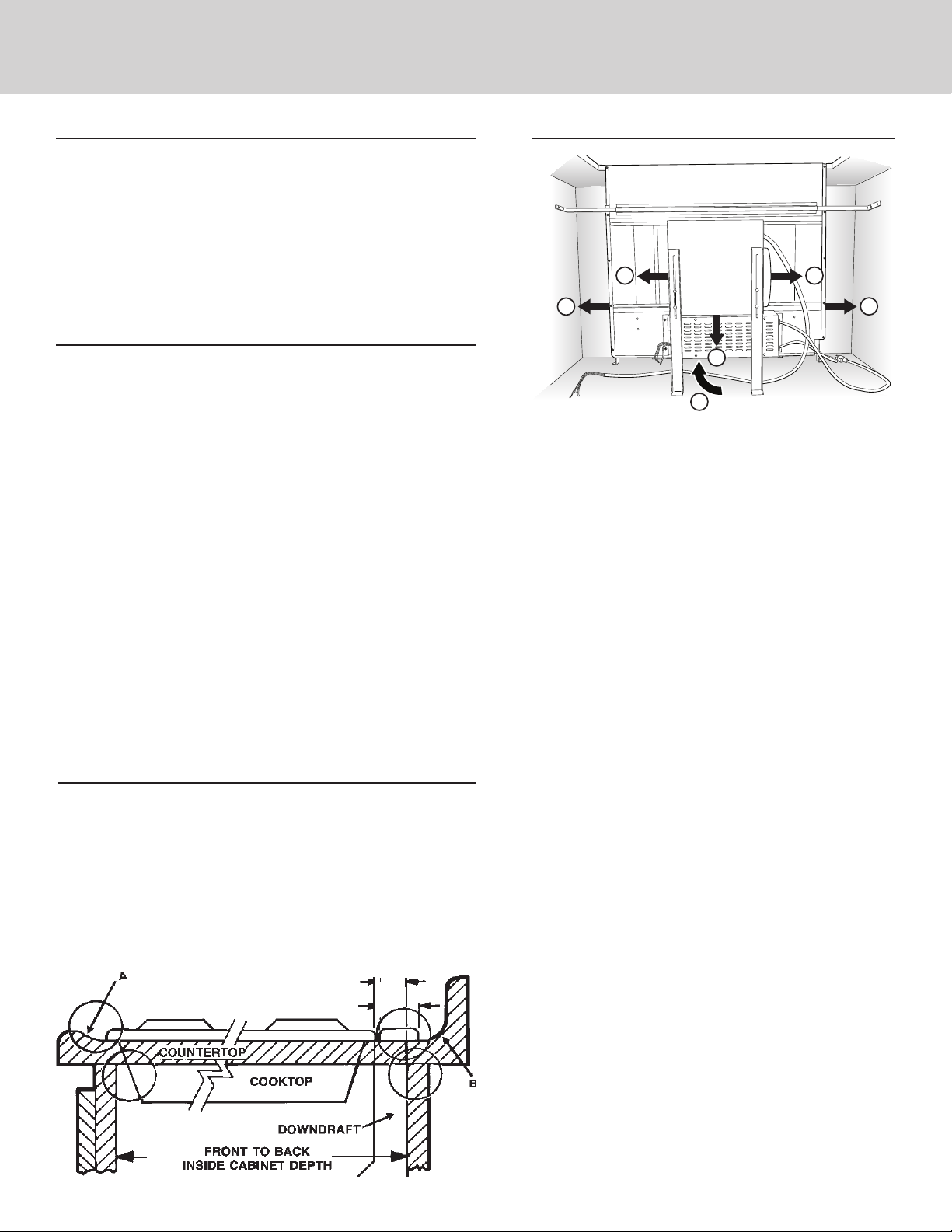
TAKE MEASUREMENTS
1. Refer to the cooktop installation instructions for dimensions of
cooktop, countertop cut-out, and cabinet requirements. However,
it is recommended that oversized cabinets be used for easier
installation.
2. Cooktop depth can vary greatly from one to another. This may
cause the fit of these two appliances to be rather tight.
Pay special attention to the areas of potential interference highlighted
above. A countertop with (A) a raised lip and/or (B) a backsplash may not
allow enough flat countertop for a proper installation. Note that 2-3/4" of
flat countertop is required behind cooktop and that 2-1/2" is necessary
between the back edge of the cooktop and the inside of cabinet back.
2-1/2"
2-3/4"
PLAN THE DUCTWORK
HOUSING
FLEX
A
D
Remote blowers use 8" or 10" round remote discharge
*
plate instead of flex blower.
1. The downdraft blower system is designed for use with
8" round ductwork using a flex blower or 10" Round
ductwork using a remote blower. (Purchase blowers
separately.) Six (6) different discharge connections are
available - with side-to-side adjustment for accurate
alignment of ductwork:
A = 8" Round, Left Discharge out of Flex Blower
B = 8" Round, Right Discharge out of Flex Blower
C = 8" Round, Down Discharge out of Flex Blower
(Electrical Box to be mounted remotely)
D = 2" x 19¼", Left Discharge out of Housing
to Remote Blower or Flex Blower in remote
location. Use 2" x 19¼" to 8" round transition,
2" x 19¼" to 10" round transition, or 2" x 19¼"
ductwork as appropriate.
E = 2" x 19¼", Right Discharge out of Housing
to Remote Blower or Flex Blower in remote
location. Use 2" x 19¼" to 8" round transition,
2" x 19¼" to 10" round transition, or 2" x 19¼"
ductwork as appropriate.
F = 2" x 19¼", Rear Discharge out of Housing
to Remote Blower or Flex Blower in remote
location. Use 2" x 19¼" to 8" round transition,
2" x 19¼" to 10" round transition, or 2" x 19¼"
ductwork as appropriate.
2. For best performance: Choose the ducting option which
allows the shortest length of ductwork and a minimum
number of elbows and transitions. Check location of
floor joists, wall studs, electrical wiring or plumbing for
possible interference.
BLOWER
*
C
F
B
E
3
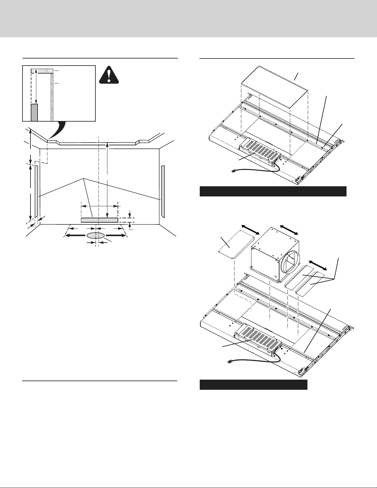
PLAN CABINET CUTOUTS
(When using Remote Discharge Plate - Hole is
PREPARE THE DOWNDRAFT
CAUTION:
BEFORE CUTTING
HOLE IN CABINET
FOR DUCTWORK,
INSIDE
CABINET BACK
19¼” centered
2”
HOLE FOR 8” or
10” ROUND DUCT
FLUSH
7
/
6 ”
8
6 7/8"
FLUSH
2”
INSIDE
CABINET
FLOOR
COUNTERTOP
CABINET
BACK
SIDE
VIEW
INSTALLATION
CENTER LINE
HOLE
FOR
2” X 19¼”
DUCT
6”*
1½”
check for interference with
floor joists, wall studs,
electrical wiring, or plumbing.
26¾”
6”*
(*Adjustable 6” Left and 6” Right)
adjustable 6” Left and 6” Right from
Installation Center Line.)
Use the dimensions in the above illustration to help plan how and
where to provide duct access through your cabinet. Generally,
1-7/8" x 19" rectangular duct will be used through left, right,
and back of cabinet - while 8" round duct will be used through
cabinet floor.
For left, right, or rear exhaust:
Allow at least 18" for transition and elbow or blower.
For left/right exhaust:
A 30" deep cabinet is recommended to align properly with
flex blower. Flex blower can be mounted to rear cabinet
wall or to a platform/frame (not provided) on the base of the
cabinet floor. (See flex blower instructions).
Cabinet depths of 24" to 30" are required - depending on the
type of cooking appliance.
PLAN THE WIRING
1. This downdraft blower using the Flex Blower (purchase
separately) draws 3.0 Amps and requires a 120 VAC, 60 Hz
circuit. If using a remote blower (purchase separately), the
system draws 6.0 Amps (max.) and requires a 120 VAC, 60
Hz circuit.
2. The unit has a 18 in. long power cord with a 3-pronged plug.
Plan to provide a grounded outlet in a location which will
allow the unit’s power cord to reach.
3. Install electrical box according to local codes.
4. The length of cable from the electrical box to the downdraft
is 20 in.
5. The length of blower (sold separately) cable to the electrical
box is 5 ft.
FRONT PANEL COVER
CLAMP
CHANNEL
Electrical panel
can be mounted
remotely.
Installations ducting through front panel opening only:
1. Place the downdraft on its back on a table or flat work surface.
2. Loosen the HEX NUTS on the CLAMP CHANNEL and remove
the FRONT PANEL COVER.
COVER
PLATE
FLEX
BLOWER
COVER PLATES
(included
with blower)
FRONT
PANEL
If blower
discharge is
down,
electrical
panel must be relocated.
See Step 6.
Installations using FLEX BLOWER only:
(Purchase Model VDVI600 Flex Blower separately.)
3. Determine its location on FRONT PANEL and whether it will
discharge to the left, right, or down.
Use a combination of COVER PLATES (3" and/or 6" wide) to
close the opening on side(s) of blower.
Slide the blower and cover plates between the LOWER
CHANNEL and the clamp channel. Tighten the hex nuts to
secure blower and panels in place.
4
(4-6) HEX
NUTS
LOWER
CHANNEL
 Loading...