

Page 1
Viking Installation Guide
VIKING GUÍA PARA LA INSTALACIÓN
VIKING GUIDE D’INSTALLATION
Freestanding Side-by-Side Refrigerator/Freezer
Refrigerador/Congelador independiente de dos puertas
Réfrigérateur/congélateur autoportants et côte à côte
Page 2

Page 3

Table of Contents / Índice / Table des matières
Refrigerator Safety ............................................ 2
Installation Requirements ................................ 2
Tools and Parts ................................................ 2
Product Dimensions ........................................ 3
Location Requirements .................................... 6
Electrical Requirements ................................... 6
Water Supply Requirements ......................... 7
Installation Instructions ................................... 8
Unpack the Refrigerator ................................ 8
Install New Water Line (If Required) ............... 9
Connect Water Supply .................................. 9
Plug In Refrigerator ........................................ 11
Prepare the Water System ........................... 12
Level Refrigerator ............................................ 13
Door Height Adjustment .............................. 14
Complete Installation ..................................... 15
Performance Checklist ..................................... 15
Service and Registration ................................ 15
Seguridad del refrigerador ............................... 16
Requisitos de instalación ................................. 16
Piezas y herramientas ........................................ 16
Medidas del producto ..................................... 17
Requisitos de ubicación ................................ 20
Requisitos eléctricos ....................................... 20
Requisitos del suministro de agua .............. 21
Instrucciones de instalación .......................... 22
Desempaque el refrigerador ........................ 22
Cómo instalar una tubería de agua nueva
(Si es necesario) ............................... 23
Conexión del suministro de agua .............. 23
Cómo enchufar el refrigerador ...................... 25
Preparación del sistema de agua .............. 26
Cómo nivelar el refrigerador ....................... 27
Cómo ajustar la altura de la puerta ........... 28
Complete la instalación ................................ 29
Lista de control de funcionamiento ........... 30
Servicio y registro .......................................... 30
Sécurité du réfrigérateur ............................. 31
Exigences d’installation ............................... 31
Outillage et pièces ........................................ 31
Dimensions du produit ................................ 32
Exigences d’emplacement ............................ 35
Spécifications électriques ............................. 35
Spécifications de l’alimentation en eau ........ 36
Instructions d’installation ................................. 37
Déballage du réfrigérateur ........................... 37
Installation d’une nouvelle canalisation d’eau
(si requise) ...................................... 38
Raccordement à la canalisation d’eau ........ 39
Brancher le réfrigérateur .............................. 40
Préparer le système d’eau ............................. 41
Nivellement du réfrigérateur ..................... 42
Ajustement de la hauteur des portes ........... 43
Achever l’installation ..................................... 44
Liste de vérification de la performance ........ 45
Intervention et enregistrement ...................... 45
1
Page 4
Refrigerator Safety
Installation Requirements
Tools and Parts
IMPORTANT:
Observe all governing codes and ordinances.
•
Installer:• Leave Installation Instructions with homeowner.
Homeowner:
• Keep Installation Instructions for future reference and for the local electrical
inspector’s use.
Keep cardboard shipping piece or plywood under refrigerator until it is installed in the
•
operating position.
Comply with installation specifications and dimensions.
•
Remove any moldings or decorative panels from kitchen cabinets that would not allow access •
to the refrigerator for service.
Contact a qualified electrical installer.
•
TOOLS NEEDED:
Gather the required tools and parts before starting installation. Read and follow the instructions
provided with any tools listed here.
Cordless drill •
•
1
•
⁄4” Nut driver and drill bit • 7⁄16” and ¹⁄2” Open-end wrenches
Flat-blade screwdriver • Two adjustable wrenches
•
• 3⁄8” and ¹⁄2” Socket wrenches
PARTS NEEDED:
1
⁄4” (6.35 mm) copper tubing with shutoff valve and a 1⁄4” (6.35 mm) compression fitting (coupling).
•
• Depending on water line connections, you may also need a
ferrule.
5
⁄16” or adjustable wrench
1
⁄4” (6.35 mm) nut and 1⁄4” (6.35 mm)
2
Page 5
Installation Requirements
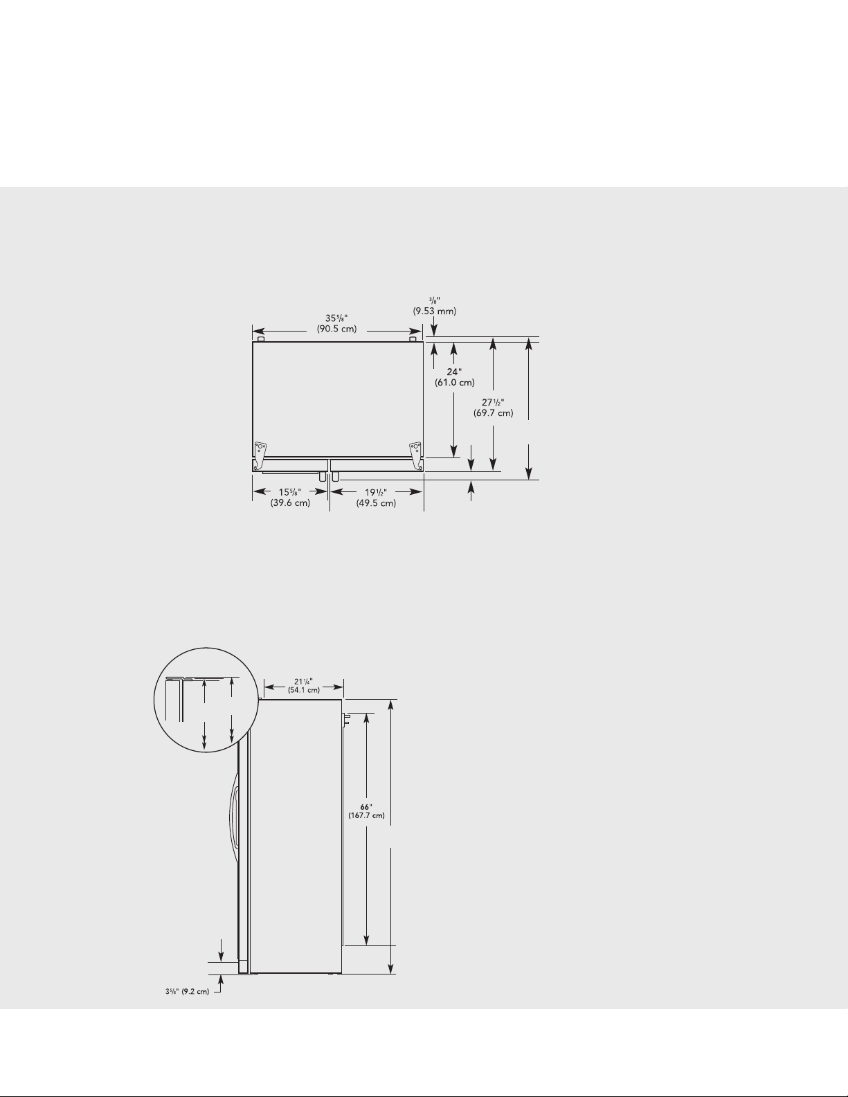
Product Dimensions
Top View
30“
(76.2 cm)
21⁄2“
(6.4 cm)
Side View
Height dimensions are shown with the leveling legs extended to the minimum height of •
below the refrigerator.
The power cord is 66” (167.7 cm) long.
•
The water line attached to the back of the refrigerator is 78” (198.1 cm) long.•
687⁄8“
(175.0 cm)
683⁄4“
(174.69 cm)
681⁄2“
(174.0 cm)
1
⁄4” (6.35 mm)
When leveling legs are fully extended to 1” (25 mm) below
the refrigerator, add 3⁄4” (19 mm) to height dimensions
3
Page 6
Installation Requirements
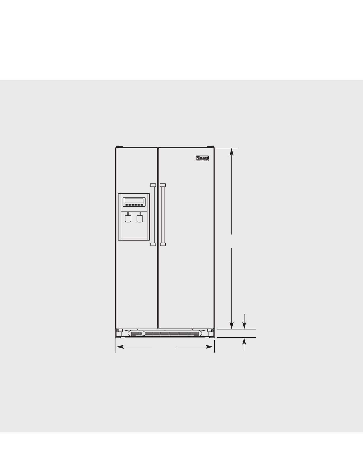
Product Dimensions
Front View
647⁄8“
(164.8 cm)
3511/
16"
(90.6 cm)
5
3
/
8"
(9.2 cm)
4
Page 7
Installation Requirements
Product Dimensions
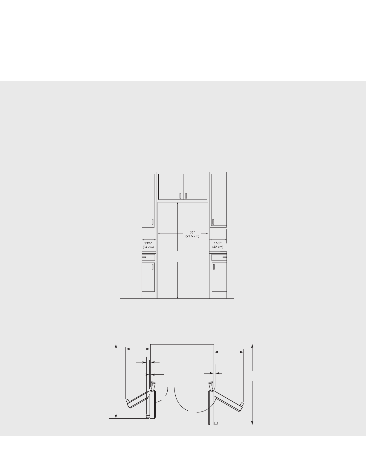
Opening Dimensions
Height dimensions are shown with the leveling legs extended to the minimum height of •
below the refrigerator.
NOTE: When leveling legs are fully extended to 1” (25 mm) below the refrigerator, add
the height dimensions.
Minimum fixed wall position is 13
•
erator door.
1
⁄4” (34 cm) from the freezer door and 161⁄2” (42 cm) from the refrig-
69“
(175.3 cm)
1
⁄4” (6.35 mm)
3
⁄4” (19 mm) to
Door Swing Dimensions
Location must permit doors to open to a minimum of 150°. Allow 131⁄4” (34 cm) minimum space between
the side wall and the freezer side of the refrigerator. Allow 16
space between the side wall and the refrigerator side.
135/8"
(34.5 cm)
5
/8"
2
3
/4"
41
(106 cm)
(6.6 cm)
1
/2"
(12.7 mm)
90°
150°
5
1
⁄2” (42 cm) minimum
17"
(43.0 cm)
0"
(0.1 mm)
45
(115.6 cm)
1
/2"
Page 8
Installation Requirements
Location Requirements
NOTES:
The cabinet depth refrigerator can be installed into a recessed opening, at the end of cabinets or
•
as a freestanding refrigerator.
If you are installing the refrigerator to t ush with the front of the base cabinets, all shoe molding
•
and baseboards must be removed from the rear of the refrigerator opening.
Location should permit doors to open fully. See the “Door Swing Dimensions” section.
•
Do not install the refrigerator near an oven, radiator, or other heat source, nor in a location where •
the temperature will fall below 55°F (13°C).
Floor must support refrigerator weight (more than 600 lbs [272 kg], door panels and contents).
•
Electrical Requirements
Before you move your refrigerator into its nal location, it is important to make sure you have the
proper electrical connection.
6
Page 9

Installation Requirements
Recommended Grounding Method
A 115 Volt, 60 Hz., AC only 15- or 20-amp fused, grounded electrical supply is required. It is recommended
that a separate circuit serving only your refrigerator be provided. Use an outlet that cannot be turned off by
a switch. Do not use an extension cord.
IMPORTANT: If this product is connected to a GFCI (Ground Fault Circuit Interrupter) protected outlet,
nuisance tripping of the power supply may occur, resulting in loss of cooling. Food quality and avor may
be affected. If nuisance tripping has occurred, and if the condition of the food appears poor, dispose of it.
NOTE: Before performing any type of installation, cleaning, or removing a light bulb, turn the control
(Thermostat, Refrigerator or Freezer Control depending on the model) to OFF and then disconnect the
refrigerator from the electrical source. When you are nished, reconnect the refrigerator to the electrical
source and reset the control (Thermostat, Refrigerator or Freezer Control depending on the model) to the
desired setting.
Water Supply Requirements
Gather the required tools and parts before starting installation. Read and follow the instructions provided
with any tools listed here.
TOOLS NEEDED:
• Flat-blade screwdriver • 1⁄4” nut driver
7
•
⁄16” and 1⁄2” open-end or • 1⁄4” drill bit
two adjustable wrenches • Cordless drill
IMPORTANT:
All installations must meet local plumbing code requirements.
•
Use copper tubing and check for leaks. Install copper tubing only in areas where the household tem-•
peratures will remain above freezing.
Water Pressure
A cold water supply with water pressure of between 30 and 120 psi (207 and 827 kPa) is required to oper-
ate the water dispenser and ice maker. If you have questions about your water pressure, call a licensed,
qualified plumber.
Reverse Osmosis Water Supply
IMPORTANT: The pressure of the water supply coming out of a reverse osmosis system going to the water
inlet valve of the refrigerator needs to be between 30 and 120 psi (207 and 827 kPa). If a reverse osmosis
water ltration system is connected to your cold water supply, the water pressure to the reverse osmosis
system needs to be a minimum of 40 to 60 psi (276 to 414 kPa). If the water pressure to the reverse osmosis system is less than 40 to 60 psi (276 to 414 kPa):
Check to see whether the sediment filter in the reverse osmosis system is blocked. Replace the filter if
•
necessary.
Allow the storage tank on the reverse osmosis system to refill after heavy usage.
•
If your refrigerator has a water lter, it may further reduce the water pressure when used in conjunction •
with a reverse osmosis system. Remove the water filter. See “Water Filtration System” in the Use & Care
Guide.
If you have questions about your water pressure, call a licensed, qualied plumber.
7
Page 10
Installation Instructions
Unpack the Refrigerator
Remove the Packaging
Dispose of/recycle all packaging materials. Do not use sharp instruments, rubbing alcohol, ammable
uids, or abrasive cleaners to remove tape or glue. These products can damage the surface of your
refrigerator.
IMPORTANT:
Clean Before Using
After you remove all of the package materials, clean the inside of your refrigerator before using it. See
the cleaning instructions in the Use & Care Guide.
3
Use
•
•
⁄8” socket wrench to remove skids.
All four leveling legs must contact the floor to support and stabilize the full weight of the refrigerator.
8
Page 11
Installation Instructions
Install New Water Line (if required)
TOOLS NEEDED:
• Flat-blade screwdriver •
7
•
⁄16” and 1⁄2” Open-end or • Cordless drill
two adjustable wrenches
1. Turn OFF main water supply. Turn ON nearest faucet long enough to clear line of water.
2. Find a
NOTE: Horizontal pipe will work, but the following procedure must be followed: Drill on the top side of
the pipe, not the bottom. This will help keep water away from the drill. This also keeps normal sedi-
ment from collecting in the valve.
3. Determine the length of copper tubing you need. Measure from the connection on the lower left
rear of refrigerator to the water pipe. Add 7 ft (2.1 m) to allow for cleaning. Use
(outside diameter) copper tubing. Be sure both ends of copper tubing are cut square.
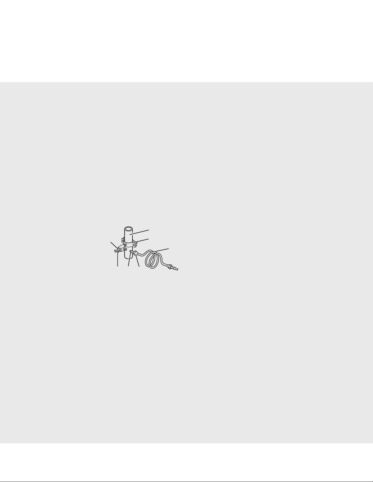
4. Using a cordless drill, drill a
5. Fasten shutoff valve to cold water pipe with pipe clamp. Be sure outlet end is solidly in the
mm) drilled hole in the water pipe and that washer is under the pipe clamp. Tighten packing nut. Tighten the pipe clamp screws slowly and evenly so washer makes a watertight seal. Do not overtighten or
you may crush the copper tubing, especially if soft (coiled) copper tubing is used. Now you are ready
to connect the copper tubing.
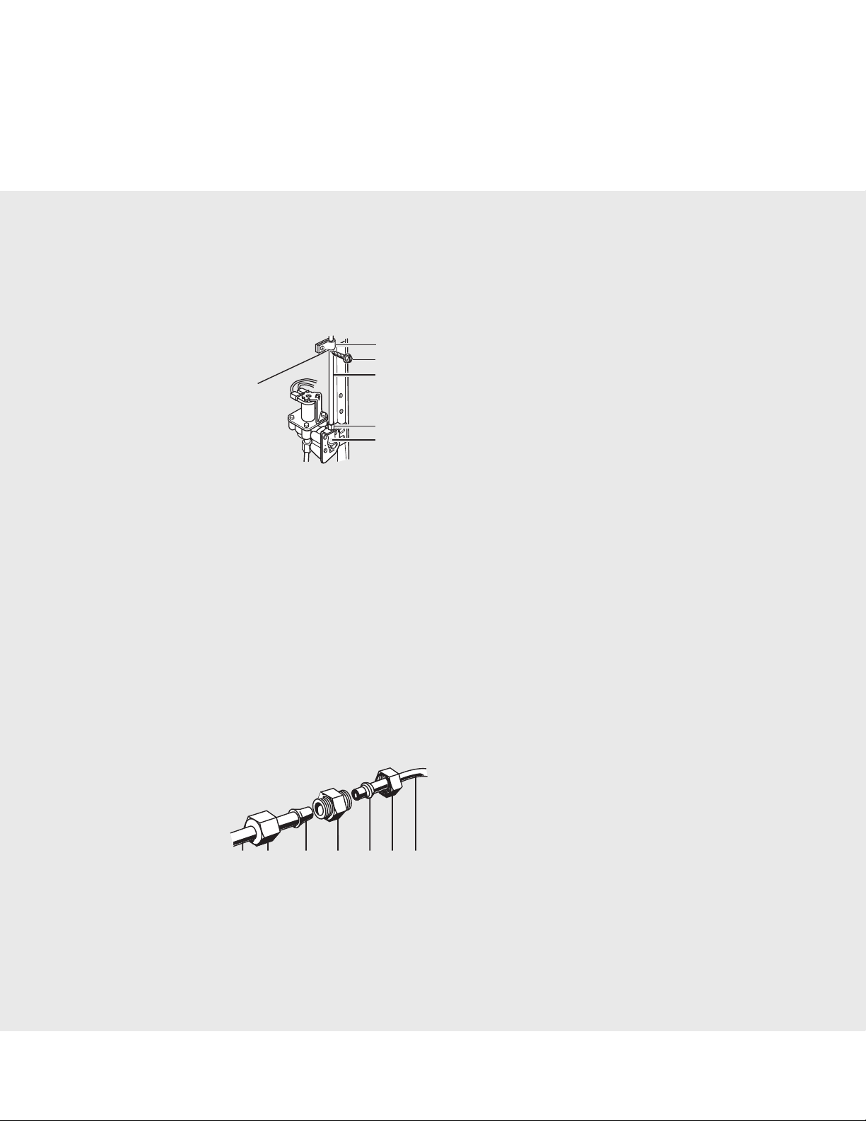
6. Slip compression sleeve and compression nut on copper tubing as shown in the diagram. Insert the
end of the tubing into the outlet end of the shutoff valve as far as it will go. Screw the compression nut
onto the outlet end with an adjustable wrench. Do not overtighten.
7. Place the free end of the tubing into a container or sink, turn ON main water supply and ush out
tubing until water is clear. Turn OFF the shutoff valve on the water pipe.
1
⁄2” (12.70 mm) to 11⁄4” (3.18 cm) vertical COLD water pipe near the refrigerator.
1
G
DEF
1
⁄4” Drill bit
1
⁄4” (6.35 mm) O.D.
⁄4” (6.35 mm) hole in the cold water pipe you have selected.
A
B
C
A. Cold water pipe
B. Pipe clamp
C. Copper tubing
D. Compression nut
E. Compression sleeve
F. Shutoff valve
G. Packing nut
1
⁄4” (6.35
Connect Water Supply
Style 1 - Connection to Water Valve
1. Unplug refrigerator or disconnect power.
2. Before attaching copper tubing to refrigerator, ush at least 2 qt (1.9 L) of water through the copper
tubing and into a bucket to get rid of any particles in the water line.
3. Check for leaks around the saddle valve. Do not overtighten clamp or sleeve. This will crush copper
tubing.
4. Attach the copper tube to the valve inlet using a compression nut and sleeve as shown. Tighten the
compression nut. Do not overtighten.
9
Page 12
Installation Instructions
5. Use the tube clamp on the back of the refrigerator to secure the tubing to the refrigerator as shown.
This will help avoid damage to the tubing when the refrigerator is pushed back against the wall.
6. Turn shutoff valve ON.
7. Check for leaks. Tighten any connections (including connections at the valve) or nuts that leak.
A
B
A. Tube clamp
C
B. Tube clamp screw
C. Copper tubing
D. Compression nut
D
E. Valve inlet
E
8. The ice maker is equipped with a built-in water strainer. If your water conditions require a second
water strainer, install it in the
from your nearest appliance dealer.
Style 2 - Connection to Water Line
1. Unplug refrigerator or disconnect power.
2. Remove and discard the shipping tape and the black nylon plug from the gray, coiled water tubing
on the rear of the refrigerator.
3. Before attaching copper tubing to refrigerator, ush at least 2 qt (1.9 L) of water through the copper
tubing and into a bucket to get rid of any particles in the water line.
4. Check for leaks around the saddle valve. Do not overtighten clamp or sleeve. This will crush copper
tubing.
5. If the gray water tube supplied with the refrigerator is not long enough, a
needed in order to connect the water tubing to an existing household water line. Thread the provided
nut onto the coupling on the end of the copper tubing.
NOTE: Tighten the nut by hand. Then tighten it with a wrench two more turns. Do not overtighten.
A B C D E F G
6. Turn shutoff valve ON.
7. Check for leaks. Tighten any nuts or connections (including connections at the valve) that leak.
1
⁄4” (6.35 mm) water line at either tube connection. Obtain a water strainer
1
⁄4” x 1⁄4” coupling is
A. Refrigerator water tubing
B. Nut (provided)
C. Bulb
D. Coupling (provided)
E. Ferrule (purchased)
F. Nut (purchased)
G. Household water line
10
Page 13
Installation Instructions
Style 3 - Connection to Shutoff Valve
1. Unplug refrigerator or disconnect power.
2. Remove and discard the shipping tape and the black nylon plug from the gray, coiled water tubing
on the rear of the refrigerator.
3. Before attaching copper tubing to refrigerator, ush at least 2 qt (1.9 L) of water through the copper
tubing and into a bucket to get rid of any particles in the water line.
4. Check for leaks around the saddle valve. Do not overtighten clamp or sleeve. This will crush copper
tubing.
5. Push the bulb end of the tubing into the water valve as far as it will go. Thread the provided nut
onto the water valve as shown.
NOTE: Tighten the nut by hand. Then tighten it with a wrench two more turns. Do not overtighten.
A. Bulb
A
B
B. Nut (provided)
6. Turn shutoff valve ON.
7. Check for leaks. Tighten any nuts or connections (including connections at the valve) that leak.
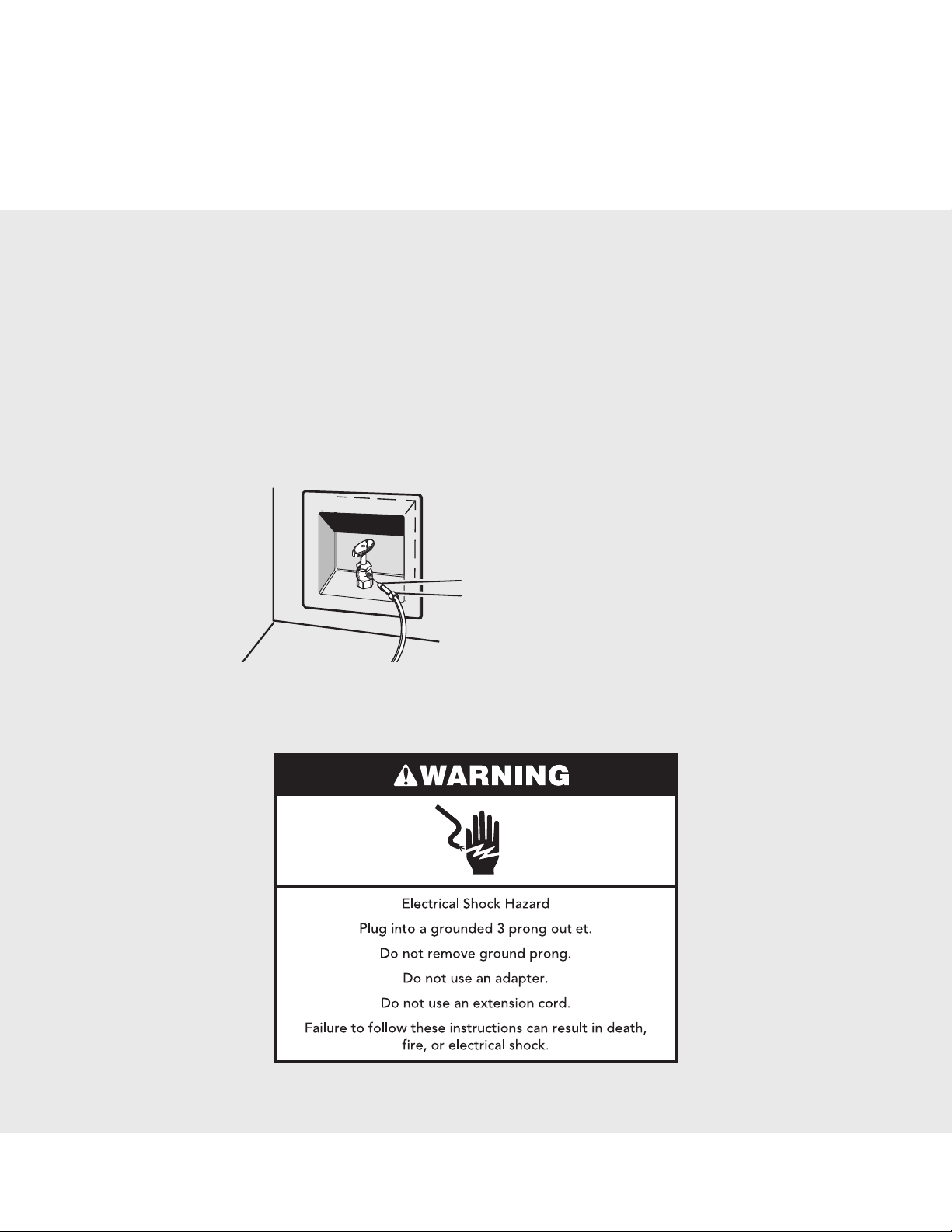
Plug in Refrigerator
1. Plug into a grounded 3 prong outlet.
11
Page 14
Installation Instructions
Prepare the Water System
Please read before using the water system.
Immediately after installation, follow the steps below to make sure that the water system is properly
cleaned.
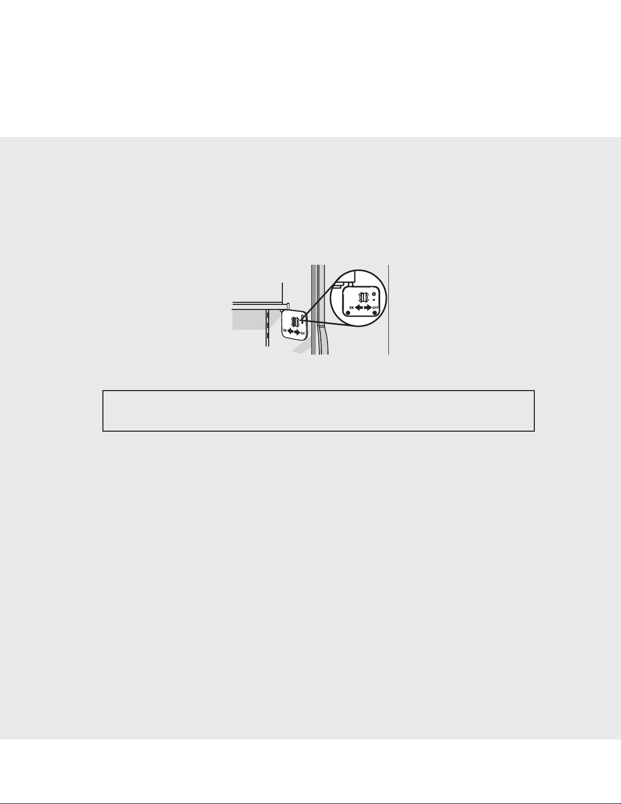
1. Open the freezer door and turn off the ice maker. The On/Off switch is located on the top right side
of the freezer compartment. Move the switch to the OFF (right) setting as shown.
NOTE: Make sure the base grille filter is properly installed and the cap is in the horizontal position.
Do not use with water that is microbiologically unsafe or of unknown quality without adequate disinfection before or after the system. Systems certified for cyst reduction may be used on disinfected waters
that may contain filterable cysts.
2. Use a sturdy container to depress and hold the water dispenser lever for 5 seconds, then release it
for 5 seconds. Repeat until water begins to ow. Once water begins to ow, continue depressing and
releasing the dispenser lever (5 seconds on, 5 seconds off) until a total of 3 gal. (12 L) has been dispensed. This will ush air from the lter and water dispensing system, and prepare the water lter for
use. Additional ushing may be required in some households. As air is cleared from the system, water
may spurt out of the dispenser.
3. Open the freezer door and turn on the ice maker. Move the switch to the ON (left) position. See the
Use & Care Guide for further instructions on the operation of your ice maker.
Allow 24 hours to produce the first batch of ice.
•
Discard the first three batches of ice produced.•
Depending on your model, you may want to select the maximum ice feature to increase the pro-•
duction of ice.
12
Page 15
Installation Instructions
Level Refrigerator
IMPORTANT: All four leveling legs must contact the floor to support and stabilize the full weight of the
refrigerator.
Remove the Base Grille
1. Open the refrigerator doors to 90°.
2. Remove base grille. Grasp the grille with both hands. Lift up and tilt the top of the grille toward you.
NOTE: Do not remove the Tech Sheets fastened behind the grille.
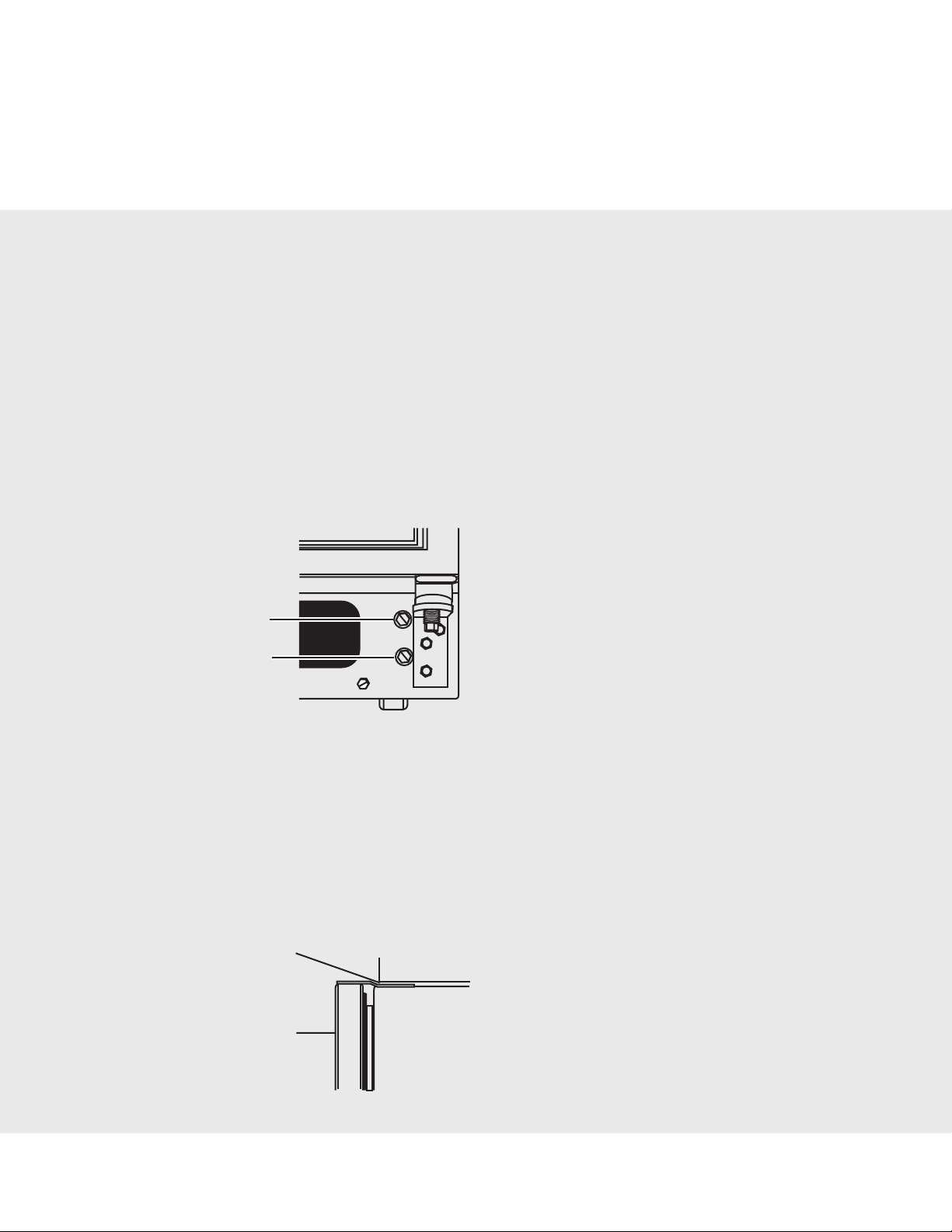
Level the Refrigerator
There is a set of two leveling bolts on each side of the refrigerator behind the base grille. The top bolts
adjust the rear of the refrigerator, and the bottom bolts adjust the front of the refrigerator.
A
B
1. Use a
to raise or to the left to lower the refrigerator. It may take several turns to adjust the tilt of the refrigerator.
NOTE: Do not unscrew the leveling bolts too much when lowering the refrigerator. The bolt head will
start to come away from the refrigerator when in the lowest position.
2. Adjust the front leveling bolts to bring the refrigerator top parallel with the cabinet above the refrigerator.
1
⁄2” (12.70 mm) socket wrench to adjust the leveling bolts. Turn the leveling bolts to the right
For standard cabinets, leave approximately
•
hinges and the cabinets.
If you do not have a cabinet above the refrigerator, simply adjust the refrigerator to make it level.
•
A
B
A. Rear leveling bolt (top)
B. Front leveling bolt (bottom)
1
⁄8” (3.18 mm) gap between the refrigerator’s top
A. Top hinges
B. Front of the refrigerator
13
Page 16

Installation Instructions
3. Adjust the rear leveling bolt to bring the refrigerator level with the side cabinets or cabinet end
panels.
4. If you want, you may now use the four leveling bolts to raise the refrigerator to reduce the gap
between the refrigerator top hinge and the cabinet opening. Check that all four leveling legs still touch
the floor and that the cabinet doors above the refrigerator open all the way.
Replace Base Grille
1. Open the refrigerator doors to 90°.
2. Replace the base grille. Place the lower clips into the bottom of the refrigerator and roll the grille up
until it snaps into place.
Door Height Adjustment
TOOLS NEEDED: 5⁄16” or adjustable wrench.
IMPORTANT: Models are preset with a quarter’s-thickness difference in door height and may not need
adjusting. If necessary after the refrigerator is loaded with food, follow the steps below to adjust the
door height up or down.
1. Locate the height adjustment bolt on the bottom hinge of the refrigerator door.
NOTE: For easier access to the height adjustment bolt, the refrigerator door should be closed.
5
2. Turn the height adjustment bolt using the
To raise the height, turn the bolt to the right.
•
To lower the height, turn the bolt to the left.•
3. Check to make sure the doors are even at the top and bottom. If necessary, continue to turn the
height adjustment bolt.
⁄16” or adjustable wrench.
14
Page 17

Installation Instructions
Complete Installation
1. Turn water supply line valve to “Open” position.
2. Turn refrigerator switch to ON position. Wait a few minutes. Check water line connections for leaks.
3. Set refrigerator and freezer compartment controls to the midpoint setting. Check that the compressor is operating properly and that all lights are working.
4. Flush water system before using. See “Prepare the Water System.”
NOTE: If construction will continue after refrigerator has been installed, set controls to OFF.
If refrigerator does not operate
Check that the circuit breaker is not tripped or household fuse blown.
•
Check that the power supply cord is plugged into a grounded 3 prong outlet.•
See “Troubleshooting” in the Use & Care Guide.•
Performance Checklist
Plug in refrigerator and verify operation.•
Connect water supply (if applicable).•
Verify ice maker bail arm is down.•
Verify dispenser operation (if applicable).•
Align/square door(s).•
Verify drain pan properly installed and no leaks •
on water connection.
Remove internal packaging and labels and wipe
•
product down.
Installer’s Information:
Installer’s name_________________________________________________
Installer’s company _____________________________________________
Service and Registration
Only authorized replacement parts may be used in performing service on the appliance. Do not repair
or replace any part of the appliance unless specifically recommended in the manual. All other servicing
should be referred to a qualified technician. Record the information indicated below. You will need it if
service is ever required. The model and serial numbers are listed on a label on the inside wall of your
refrigerator.
Model number ___________________________________________________
Serial number ____________________________________________________
Purchase date ____________________________________________________
Installation date __________________________________________________
Dealer name______________________________________________________
Address __________________________________________________________
________________________________________________________________
15
Page 18

Seguridad del refrigerador
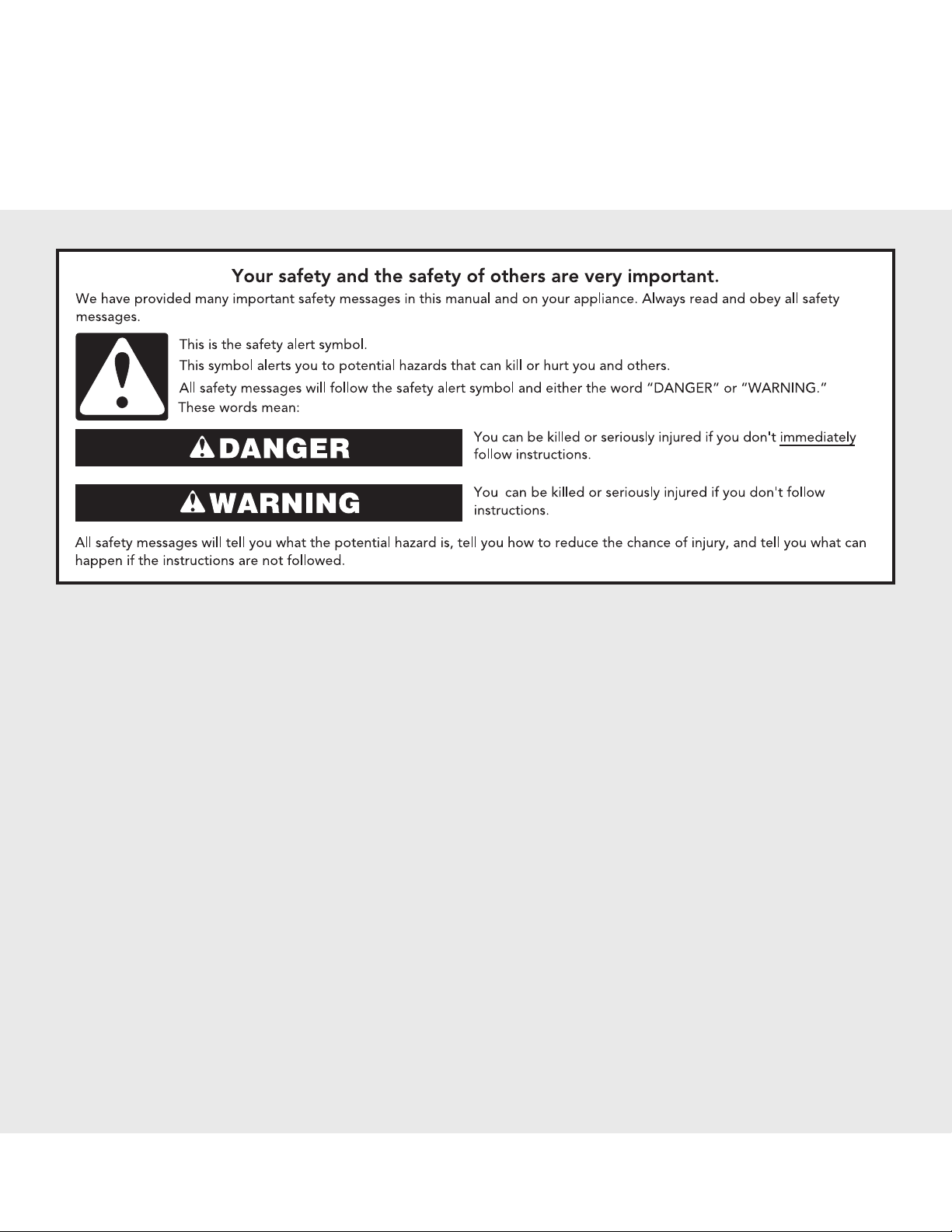
Si no sigue las instrucciones de inmediato, usted puede
morir o sufrir una lesión grave.
Si no sigue las instrucciones, usted puede morir o sufrir
una lesión grave.
Todos los mensajes de seguridad le dirán el peligro potencial, le dirán cómo reducir las posibilidades de sufrir una lesión y lo que
puede suceder si no se siguen las instrucciones.
Su seguridad y la seguridad de los demás es muy importante.
Hemos incluido muchos mensajes importantes de seguridad en este manual y en su electrodoméstico. Lea y obedezca siempre
todos los mensajes de seguridad.
ADVERTENCIA
PELIGRO
Este es el símbolo de advertencia de seguridad.
Este símbolo le llama la atención sobre peligros potenciales que pueden ocasionar la muerte o una lesión a
usted y a los demás.
Todos los mensajes de seguridad irán a continuación del símbolo de advertencia de seguridad y de la palabra
“PELIGRO” o “ADVERTENCIA”. Estas palabras significan:
Requisitos de la instalación
Piezas y herramientas
IMPORTANTE:
Observe todos los códigos y reglamentos aplicables.
•
Instalador: Deje las instrucciones de instalación con el propietario.•
Propietario: Guarde las instrucciones de instalación para referencia futura y para que puedan ser •
usadas por el inspector eléctrico local.
Mantenga un tramo de cartón de empaque o de madera contrachapada debajo del refrigerador
•
hasta que lo instale en su ubicación final.
Cumpla con las especificaciones y medidas de instalación.
•
Saque todas las molduras o paneles decorativos de los gabinetes de la cocina que impidan el ac-•
ceso al refrigerador para darle servicio.
Contacte a un instalador electricista calificado.
•
HERRAMIENTAS NECESARIAS:
Reúna las herramientas y piezas necesarias antes de comenzar la instalación. Lea y siga las instrucciones provistas con cualquiera de las herramientas enlistadas aquí.
Taladro inalámbrico • Llaves de boca de
•
Llave para tuercas de
•
Destornillador de hoja plana • Llaves de cubo de
•
Llave de
•
PIEZAS NECESARIAS:
• Una tubería de cobre de
(acoplamiento) de
• Dependiendo de las conexiones de la línea de agua, usted también puede necesitar una tuerca
1
de
⁄4”(6,35 mm) y una férula de 1⁄4”(6,35 mm)
5
⁄16” o llave ajustable
1
⁄4” y broca • Dos llaves ajustables
1
1
⁄4” (6,35 mm)
⁄4” (6,35 mm) con válvula de cierre y un accesorio de compresión
7
⁄16” y 1⁄2”
3
⁄8” y 1⁄2”
16
Page 19

Requisitos de la instalación
Medidas del producto
Vista superior
30“
(74,9 cm)
21⁄2“
(6,4 cm)
Vista lateral
Las medidas de altura indicadas consideran las patas niveladoras extendidas como mínimo •
mm) por debajo del refrigerador.
El cable de suministro de energía es de 66” (167,7 cm) de largo.
•
La línea de agua ajustada a la parte posterior del refrigerador es de 78” (198,1 cm) de largo.•
687⁄8“
(175,0 cm)
683⁄4“
(174,69 cm)
Si las patas niveladoras están totalmente extendidas 1” (25
mm) por debajo del refrigerador, agregue 3⁄4” (19 mm) a las
medidas de altura.
681⁄2“
(174,0 cm)
1
⁄4” (6,35
17
Page 20

Requisitos de la instalación
Medidas del producto
Vista frontal
647⁄8“
(164,8 cm)
3511/
16"
(90,6 cm)
18
5
3
/
8"
(9,2 cm)
Page 21

Requisitos de la instalación
Medidas del producto
Medidas de abertura
Las medidas de altura indicadas consideran las patas niveladoras extendidas como mínimo •
mm) por debajo del refrigerador.
NOTA: Si las patas niveladoras están totalmente extendidas 1” (25 mm) por debajo del refrigerador,
agregue 3⁄4”(19 mm) a las medidas de altura.
La posición fija mínima respecto de la pared es de 13
•
1
16
⁄2” (42 cm) desde la puerta del refrigerador.
69“
(175,3 cm)
1
⁄4”(34 cm) desde la puerta del congelador y de
1
⁄4” (6,35
Medidas de oscilación de las puertas
La ubicación debe permitir que las puertas se abran a un mínimo de 150°. Deje un espacio mínimo de
1
13
⁄4” (34 cm) entre la pared y el lado del congelador del refrigerador. Deje un espacio mínimo de 161⁄2”
(42 cm) entre la pared y el lado del refrigerador
19
Page 22

Requisitos de instalación
Requisitos de ubicación
NOTAS:
El refrigerador con profundidad de armario puede instalarse empotrado, al nal de los armarios o
•
separado.
Si está instalando el refrigerador para estar alineado con el frente de los armarios de base, se de-
•
ben quitar todas las molduras y los zócalos de la parte poserior de la abertura del refrigerador.
La ubicación deberá permitir que las puertas se abran completamente. Vea la sección “Medidas
•
de oscilación de las puertas”.
No instale el refrigerador cerca de un horno, radiador u otra fuente de calor ni en una ubicación en
•
la que la temperatura puede bajar de los 55° F (13° C).
El piso debe soportar el peso del refrigerador (más de 600 libras [272 kg], los paneles de las puer-
•
tas y el contenido).
Requisitos eléctricos
20
Page 23

Requisitos de instalación
Antes de mover el refrigerador a su posición denitiva, es importante asegurarse que Ud. tiene la conexión
eléctrica adecuada.
Método de conexión a tierra recomendado
Se requiere una fuente de energía eléctrica de 115 Voltios, 60 Hz., CA solamente y con fusibles de 15 ó 20
amperios, conectada a tierra. Se recomienda que se use un circuito separado sólo para su refrigerador. Use
un tomacorriente que no se puede apagar con un interruptor. No use un cable eléctrico de extensión.
IMPORTANTE: Si este producto está conectado a un tomacorriente protegido por GFCI (Ground Fault
Circuit Interrupter- Interruptor de circuito de falla eléctrica de puesta a tierra), puede ocurrir un disparo
molesto del suministro de corriente, lo que resultará en la pérdida de refrigeración. Esto puede afectar la
calidad y el sabor de los alimentos. Si ha ocurrido un disparo molesto, y el alimento aparenta estar en
malas condiciones, deshágase del mismo.
NOTA: Antes de realizar cualquier tipo de instalación, limpieza o de quitar un foco de luz, ponga el control
(del termostato, del refrigerador o del congelador dependiendo del modelo) en la posición OFF (apagado)
y luego desconecte el refrigerador de la fuente de energía. Cuando Ud. haya terminado, reconecte el
refrigerador a la fuente de energía eléctrica y vuelva a poner el control (del termostato, del refrigerador o
del congelador dependiendo del modelo) en la posición deseada.
Requisitos del suministro de agua
Reúna las herramientas y piezas necesarias antes de comenzar la instalación. Lea y siga las instrucciones
provistas con cualquiera de las herramientas enlistadas aquí.
HERRAMIENTAS NECESARIAS:
• Destornillador de hoja plana • Llave para tuercas de 1⁄4”
• Llaves de boca de
to dos llaves ajustables • Taladro inalámbrico
IMPORTANTE:
Todas las instalaciones deben hacerse de acuerdo a los requerimientos locales de plomería.
•
Use tuberías de cobre y revise si hay fugas. Instale tubería de cobre sólo en áreas donde la tempera-•
tura va a permanecer por encima del punto de congelación.
Presión del agua
Se necesita un suministro de agua fría con presión de agua entre 30 y 120 lbs/pulg² (207 y 827 kPa) para
hacer funcionar el despachador de agua y la fábrica de hielo. Si usted tiene preguntas acerca de la presión
de agua, llame a un plomero competente autorizado.
Suministro de agua de ósmosis inversa
IMPORTANTE: La presión del suministro de agua que sale de un sistema de ósmosis inversa y va a la vál-
vula de entrada de agua del refrigerador necesitará ser entre 30 y 120 lbs/pulg² (207 y 827 kPa).
Si se conecta un sistema de ltración de agua de ósmosis inversa al suministro de agua fría, la presión de
agua al sistema de ósmosis inversa necesitará ser de un mínimo de 40 a 60 lbs/pulg² (276 a 414 kPa).
7
⁄16” and 1⁄2” • Broca de 1⁄4”
21
Page 24

Instrucciones de instalación
Si la presión del agua del sistema de ósmosis inversa es menor de 40 a 60 lbs/pulg² (276 a 414 kPa):
Fíjese si el filtro de sedimentos en el sistema de ósmosis inversa está bloqueado y reemplácelo si fuera
•
necesario.
Deje que se vuelva a llenar el tanque de almacenaje del sistema de ósmosis inversa después del uso
•
intenso.
Si su refrigerador tiene un cartucho del ltro de agua, se podrá reducir la presión aún más si se usa en
•
conjunto con un sistema de ósmosis inversa. Quite el cartucho del filtro de agua. Vea “Sistema de filtración
de agua” en el Manual de uso y cuidado.
Si tiene preguntas acerca de la presión del agua, llame a un plomero competente autorizado.
Desempaque el refrigerador
Cómo quitar los materiales de empaque
Deshágase de todos los materiales de embalaje o recíclelos. No use instrumentos losos, alcohol para fricciones, líquidos inamables o productos de limpieza abrasivos para eliminar los restos de cinta o goma.
Estos productos pueden dañar la superficie de su refrigerador.
IMPORTANTE:
Use una llave de cubo de
•
Las cuatro patas niveladoras deberán tocar el piso para soportar y estabilizar el peso total del refrigerador.
•
Cómo limpiar su refrigerador antes de usarlo
Una vez que usted haya quitado todos los materiales de empaque, limpie el interior de su refrigerador antes de
usarlo. Vea las instrucciones de limpieza en el Manual de Uso y Cuidado.
3
⁄8” para quitar la plataforma.
22
Page 25

Instrucciones de instalación
Cómo instalar una tubería de agua nueva (si es necesario)
HERRAMIENTAS NECESARIAS:
• Destornillador de hoja plana • Broca de
• Llaves de boca de
1
⁄2” o dos llaves ajustables
1. CIERRE el suministro principal de agua. ABRA la llave de agua más cercana el tiempo suficiente para
que la tubería de agua se vacíe.
2. Busque una tubería vertical de agua FRÍA de
NOTA: Una tubería horizontal funcionará, pero debe seguirse el procedimiento indicado a continuación: taladre por el lado de arriba de la tubería, no por debajo. Esto ayudará a mantener el agua
alejada del taladro. Esto también evita que se acumule el sedimento normal en la válvula.
3. Determine la longitud de la tubería de cobre que necesite. Mida desde la conexión de la parte baja
trasera izquierda del refrigerador hasta la tubería de agua. Agregue 7 pies (2,1 m) para poder mover
el refrigerador para limpiarlo. Use tubería de cobre de
que ambos extremos de la tubería de cobre están cortados a escuadra.
4. Usando un taladro inalámbrico, haga un oricio de
eligió.
5. Sujete la válvula de cierre al tubo de agua fría empleando la abrazadera para tubería. Asegúrese
de que el extremo de salida esté rmemente insertado en el oricio de ¼” (6,35 mm) en la tubería de
agua y que la arandela esté debajo de la abrazadera para tubería. Ajuste la tuerca de presión. Apriete
los tornillos de la abrazadera para tubería con cuidado y en forma pareja de manera que la arandela
provea un cierre hermético. No apriete demasiado porque se puede quebrar la tubería de cobre, especialmente si usa la tubería de cobre blanda (enrollada). Ahora está listo para conectar la tubería de
cobre
6. Deslice la manga de compresión y la tuerca de compresión sobre la tubería de cobre como se
muestra en el gráfico. Inserte el extremo de la tubería en el extremo de salida hasta donde sea posible.
Atornille la tuerca de compresión sobre el extremo de salida con una llave ajustable. No apriete
demasiado.
7. Coloque el extremo libre de la tubería dentro de un recipiente o fregadero, ABRA el suministro
principal de agua para lavar la tubería hasta que el agua salga limpia. CIERRE la válvula de cierre del
tubo de agua.
7
⁄16” and • Taladro inalámbrico
1
⁄2” (12,70 mm) a 11⁄4” (3,18 cm) cerca del refrigerador.
A
G
B
C
DEF
1
⁄4”
1
⁄4” (6,35 mm) de diámetro externo. Asegúrese
1
⁄4” (6,35 mm) en la tubería de agua fría que Ud.
A. Tubería de agua fría
B. Abrazadera para tubería
C. Tubería de cobre
D. Tuerca de compresión
E. Manga de compresión
F. Válvula de cierre
G. Tuerca de presión
Conexión del suministro de agua
Estilo 1 - Conexión a la válvula de agua
1. Desenchufe el refrigerador o desconecte el suministro de energía.
23
Page 26

Instrucciones de instalación
2. Antes de jar la tubería de cobre al refrigerador, deje correr por lo menos 2 qt (1,9 L) de agua a
través de la tubería de cobre y dentro de una cubeta para eliminar cualquier partícula dentro de la
tubería de agua.
3. Busque fugas alrededor de la válvula tipo montura. No apriete demasiado la abrazadera o la manga.
Se puede quebrar la tubería de cobre.
4. Fije el tubo de cobre a la entrada de la válvula usando una tuerca de compresión y manga de compresión como se muestra. Ajuste la tuerca de compresión. No apriete demasiado.
5. Use la abrazadera para tubería en la parte trasera del refrigerador para afianzar la tubería al refrigerador según se muestra. Esto ayudará a evitar daños en la tubería cuando el refrigerador se empuje
nuevamente contra la pared.
6. ABRA la válvula de cierre.
7. Revise si hay fugas. Ajuste las conexiones (incluso las de la válvula) o tuercas que tienen fugas.
A
B
A. Tube clamp
C
B. Tube clamp screw
C. Copper tubing
D. Compression nut
D
E. Valve inlet
E
8. La fábrica de hielo está equipada con un filtro de agua incorporado. Si las condiciones del agua
local requieren un segundo ltro de agua, se debe instalar en la línea de agua de ¼” (6,35 mm) en
cualquiera de las conexiones de la tubería. Obtenga un filtro de agua del distribuidor de
electrodomésticos más cercano a su domicilio.
Estilo 2 - Conexión a la línea de agua
1. Desenchufe el refrigerador o desconecte el suministro de energía.
2. Quite y deseche la cinta de empaque y el tapón de nailon negro de la tubería gris de agua enrollada
en la parte trasera del refrigerador.
3. Antes de jar la tubería de cobre al refrigerador, deje correr por lo menos 2 qt (1,9 L) de agua a
través de la tubería de cobre y dentro de una cubeta para eliminar cualquier partícula dentro de la
tubería de agua.
4. Busque fugas alrededor de la válvula tipo montura. No apriete demasiado la abrazadera o la manga.
Se puede quebrar la tubería de cobre.
5. Si el tubo de agua gris suministrado con el refrigerador no es sucientemente largo, se necesita un
acoplamiento de ¼” x ¼” para conectar la tubería de agua a una línea doméstica de agua existente.
Enrosque la tuerca provista sobre el acoplamiento en el extremo de la tubería de cobre.
NOTA: Apriete la tuerca a mano. Luego apriétela dos vueltas con una llave de tuercas. No apriete
demasiado.
A B C D E F G
A. Tubería de agua al refrigerador
B. Tuerca (provista)
C. Bulbo
D. Acoplamiento (provisto)
E. Férula (adquirida)
F. Tuerca (adquirida)
G. Línea de agua de la casa
24
Page 27

Instrucciones de instalación
6. ABRA la válvula de cierre.
7. Revise si hay fugas. Apriete aquellas tuercas o conexiones que tengan fugas (incluidas las conexiones en la
válvula).
Estilo 3 - Conexión a la válvula de cierre
1. Desenchufe el refrigerador o desconecte el suministro de energía.
2. Quite y deseche la cinta de empaque y el tapón de nailon negro de la tubería gris de agua enrollada en la
parte trasera del refrigerador.
3. Antes de jar la tubería de cobre al refrigerador, deje correr por lo menos 2 qt (1,9 L) de agua a través de la
tubería de cobre y dentro de una cubeta para eliminar cualquier partícula dentro de la tubería de agua.
4. Busque fugas alrededor de la válvula tipo montura. No apriete demasiado la abrazadera o la manga. Se
puede quebrar la tubería de cobre.
5. Empuje el extremo del bulbo de la tubería dentro de la válvula de agua hasta que se detenga. Enrosque la
tuerca provista sobre la válvula de agua como se muestra.
NOTA: Apriete la tuerca a mano. Luego apriétela 2 vueltas con una llave de tuercas. No apriete demasiado.
A. Bulbo
B. Tuerca (provista)
A
B
6. ABRA la válvula de cierre.
7. Revise si hay fugas. Apriete aquellas tuercas o conexiones que tengan fugas (incluidas las conexiones en la
válvula).
Cómo enchufar el refrigerador
25
Page 28

Instrucciones de instalación
1. Enchufe a un contacto de pared de conexión a tierra de 3 terminales.
Preparación del sistema de agua
Sírvase leer antes de usar el sistema de agua.
Inmediatamente después de la instalación, siga los pasos a continuación para asegurarse de que el
sistema de agua esté debidamente limpio.
1. Abra la puerta del congelador y apague la fábrica de hielo. El interruptor de encendido/apagado
(On/Off) se encuentra en el lado superior derecho del compartimiento del congelador. Mueva el interruptor a la posición OFF (Apagado - hacia la derecha) como se muestra.
NOTA: Asegúrese de que el filtro de la rejilla de la base esté instalado adecuadamente y que la tapa
esté en la posición horizontal.
No use con agua que no sea microbiológicamente segura o que sea de calidad desconocida sin
desinfectarla adecuadamente antes o después del sistema. Pueden usarse sistemas certificados para la
reducción de quistes en aguas desinfectadas que puedan contener quistes filtrables.
2. Use un recipiente resistente para oprimir y sostener la barra del despachador por 5 segundos,
luego suéltela por 5 segundos. Repita hasta que el agua comience a correr. Una vez que el agua haya
comenzado a correr, continúe presionando y soltando la barra del despachador (5 segundos activado,
5 segundos desactivado) hasta despachar un total de 3 gal. (12 L). Esto eliminará el aire en el filtro y
en el sistema de despachado de agua y preparará el filtro de agua para ser usado. En algunas casas se
podrá requerir enjuague adicional. A medida que sale aire del sistema, es posible que salgan chorros
de agua repentinos del despachador.
3. Abra la puerta del congelador y encienda la fábrica de hielo. Mueva el interruptor a la posición ON
(Encendido - hacia la izquierda). Vea el Manual de Uso y Cuidado para obtener más instrucciones sobre
el funcionamiento de su fábrica de hielo.
Deje transcurrir 24 horas para la producción del primer lote de hielo.
•
Deshágase de los tres primeros lotes de hielo producidos.•
Dependiendo de su modelo, puede ser que Ud. desee elegir la característica máxima de hielo •
para incrementar la producción de hielo.
26
Page 29

Instrucciones de instalación
Cómo nivelar el refrigerador
IMPORTANTE: Las cuatro patas niveladoras deberán hacer contacto con el piso para soportar y estabilizar el peso total del refrigerador.
Cómo quitar la rejilla de la base
1. Abra las puertas del refrigerador a 90°.
2. Quite la rejilla de la base. Tome la rejilla con las dos manos. Levante e incline la parte superior de la
rejilla hacia Ud.
NOTA: No quite las Hojas Técnicas que están sujetas detrás de la rejilla.
Nivele el refrigerador
A cada lado del refrigerador detrás de la rejilla de la base hay un juego de dos pernos de nivelación.
Los pernos superiores ajustarán la parte trasera del refrigerador y los pernos inferiores ajustarán la
parte frontal del refrigerador.
A
B
1. Utilice una llave de tubo de
niveladores a la derecha para levantar el refrigerador o a la izquierda para bajarlo. Puede precisar darle
varias vueltas para ajustar la inclinación del refrigerador.
NOTA: No desenrosque demasiado los pernos niveladores cuando esté bajando el refrigerador. La
cabeza del perno comenzará a salirse del refrigerador cuando esté en la posición más baja.
2. Ajuste los pernos niveladores frontales para llevar la parte superior del refrigerador paralela al armario encima del refrigerador.
Para armarios estándares, deje un espacio de aproximadamente
•
Si no tiene un armario encima del refrigerador, simplemente ajuste el refrigerador para nivelarlo.
•
A
B
1
⁄2” (12,70 mm) para ajustar los pernos niveladores. Gire los pernos
A. Perno nivelador trasero (superior)
B. Perno nivelador frontal (inferior)
1
⁄8” (3,18 mm) entre las bisagras
A. Bisagras superiores
B. Frente del refrigerador
27
Page 30

Instrucciones de instalación
3. Ajuste el perno nivelador trasero para nivelar el refrigerador con los armarios laterales o los paneles
extremos del armario.
4. Si lo desea, puede usar ahora los cuatro pernos niveladores para levantar el refrigerador y reducir
el espacio entre la bisagra superior del refrigerador y la abertura del armario. Asegúrese de que las
cuatro patas niveladoras todavía tocan el piso y que las puertas del armario encima del refrigerador
abren completamente.
Vuelva a colocar la rejilla de la base
1. Abra las puertas del refrigerador a 90°.
2. Vuelva a colocar la rejilla de la base. Coloque las abrazaderas inferiores en la parte inferior del refrigerador y deslice la rejilla hacia arriba hasta que calce en su lugar..
Cómo ajustar la altura de la puerta
HERRAMIENTAS NECESARIAS: 5⁄16” o llave ajustable.
IMPORTANT: Los modelos son preajustados con una diferencia de espesor de una moneda de 25
centavos en la altura de la puerta y es posible que no necesiten ajuste.
Si fuera necesario después de llenar el refrigerador con alimentos, ajustar la altura de la puerta hacia
arriba o hacia abajo, siga los pasos que se dan a continuación.
1. Ubique el perno para ajustar la altura en la bisagra inferior de la puerta del refrigerador.
NOTA: Para fácil acceso al perno para ajustar la altura, la puerta del refrigerador debe estar cerrada.
2. Gire el perno para ajustar la altura usando la llave de tuerca de
Para elevar la altura, gire el perno hacia la derecha.
•
Para bajar la altura, gire el perno hacia la izquierda•
3. Revise para asegurase de que las puertas estén a nivel en la parte superior y en la parte inferior. De
ser necesario, continúe girando el perno para ajustar la altura.
28
5
⁄16” o una llave de tuerca ajustable.
Page 31

Instrucciones de instalación
Complete la instalación
1. Gire la válvula de la tubería de suministro de agua a la posición “Abierta”.
2. Gire el interruptor del refrigerador a la posición ON (encendido). Espere unos minutos. Busque
fugas en las conexiones de la tubería de agua.
3. Fije los controles del compartimiento del refrigerador y del congelador en su posición central. Verifique que el compresor está funcionando correctamente y que todas las luces funcionan.
4. Enjuague el sistema de agua antes de utilizarlo. Vea “Prepare el sistema de agua”.
NOTA: Si se sigue construyendo después de haber instalado el refrigerador, je los controles en OFF
(Apagado).
Si el refrigerador no funciona
Verifique que el disyuntor no se haya disparado o que no haya explotado un fusible.
•
Verifique que el cable del suministro de energía esté enchufado en un contacto de pared de con-•
exión a tierra de 3 terminales.
Vea “Solución de problemas” en el Manual de Uso y Cuidado.
•
29
Page 32

Lista de control de funcionamiento
Enchufe el refrigerador y verifique el funcionamiento.•
Conecte el suministro de agua (si se aplica).•
Verifique que el brazo de alambre de la fábrica de hielo esté hacia •
abajo.
Verifique el funcionamiento del despachador (si se aplica).•
Alinee/ponga a escuadra la(s) puerta(s).
•
Verifique que la bandeja de goteo esté debidamente instalada y que no •
haya fugas en la conexión de agua.
Quite las piezas de empaque interiores y las etiquetas y pásele un paño
•
al producto.
Información acerca del instalador:
Nombre del instalador ___________________________________________
Compañía del instalador _________________________________________
Servicio y registro
Solamente piezas de repuesto autorizadas podrán usarse al prestarle servicio técnico al electrodoméstico. No repare ni reemplace ninguna pieza del electrodoméstico a menos que se recomiende específicamente en el manual. Cualquier otro servicio se debe dejar en las manos de un técnico competente.
Anote la información que se indica a continuación. La necesitará en caso de necesitar servicio. Los
números de modelo y de serie están indicados en una etiqueta, en la pared interior de su refrigerador.
Número de modelo _______________________________________________
Número de serie _________________________________________________
Fecha de compra _________________________________________________
Fecha de instalación ______________________________________________
Nombre del distribuidor __________________________________________
Dirección_______________________________________________________
________________________________________________________________
30
Page 33

Sécurité du réfrigérateur
Risque possible de décès ou de blessure grave si vous ne
suivez pas immédiatement les instructions.
Risque possible de décès ou de blessure grave si vous
ne suivez pas les instructions.
Tous les messages de sécurité vous diront quel est le danger potentiel et vous disent comment réduire le risque de blessure et
ce qui peut se produire en cas de non-respect des instructions.
Votre sécurité et celle des autres est très importante.
Nous donnons de nombreux messages de sécurité importants dans ce manuel et sur votre appareil ménager. Assurez-vous de
toujours lire tous les messages de sécurité et de vous y conformer.
AVERTISSEMENT
DANGER
Voici le symbole d’alerte de sécurité.
Ce symbole d’alerte de sécurité vous signale les dangers potentiels de décès et de blessures graves à vous
et à d’autres.
Tous les messages de sécurité suivront le symbole d’alerte de sécurité et le mot “DANGER” ou
“AVERTISSEMENT”. Ces mots signifient :
Conditions d’installation
Outillage et pièces
IMPORTANT:
Respecter toutes les prescriptions des codes et règlements en vigueur.
•
Installateur : Remettre les instructions d’installation au propriétaire.•
Propriétaire : Conserver les instructions d’installation pour consultation ultérieure et pour utilisation •
par l’inspecteur local des installations électriques.
Garder la pièce de carton ou de contreplaqué d’expédition sous le réfrigérateur jusqu’à son instal
•
lation à l’emplacement de service.
Observer les spécifications et dimensions d’installation.
•
Retirer toute moulure ou tout panneau décoratif des meubles de cuisine qui entraveraient l’accès •
au réfrigérateur lors d’une intervention de réparation.
Communiquer avec un électricien qualifié.
•
OUTILLAGE REQUIS :
Rassembler les outils et pièces nécessaires avant de commencer l’installation. Lire et suivre les instructions fournies avec les outils indiqués ici.
Perceuse sans l • Clés plates de
•
Tourne-écrou de
•
Tournevis à lame plate • Clés à douille de
•
•
PIÈCES NÉCESSAIRES :
• Un tube en cuivre de
(6,35 mm).
• Selon les raccordements de la canalisation d’eau, il vous faudra peut-être aussi un écrou de
(6,35 mm) et une bague de
Clé de
5
⁄16” ou clé à molette
1
⁄4” et foret • Deux clés à molette
1
⁄4” (6,35 mm) avec un robinet d’arrêt et un raccord de compression de 1⁄4”
7
⁄4” (6,35 mm).
31
7
⁄16” et 1⁄2”
3
⁄8” et 1⁄2”
1
⁄4”
Page 34

Conditions d’installation
Dimensions du produit
Vue de dessus
30“
(74,9 cm)
21⁄2“
(6,4 cm)
Vue latérale
Les dimensions de hauteur sont illustrées avec les pieds de nivellement déployés à la hauteur mini-•
mum de 1⁄4” (6,35 mm) sous le réfrigérateur.
Le cordon d’alimentation mesure 66” (167,7 cm) de long.
•
La canalisation d’eau xée à l’arrière du réfrigérateur mesure 78” (198,1 cm) de long.•
683⁄4“
(174,69 cm)
687⁄8“
(175,0 cm)
681⁄2“
(174,0 cm)
Lorsque les pieds de nivellement sont complètement
déployés à 1” (25 mm) sous le réfrigérateur, ajouter
3
⁄4” (19 mm) aux dimensions de hauteur.
32
Page 35

Conditions d’installation
Dimensions du produit
Vue de face
647⁄8“
(164,8 cm)
3511/
16"
(90,6 cm)
33
5
3
/8"
(9,2 cm)
Page 36

Conditions d’installation
Dimensions du produit
Dimensions de l’ouverture
Les dimensions de hauteur sont illustrées avec les pieds de nivellement déployés à la hauteur •
minimum de 1⁄4” (6,35 mm) sous le réfrigérateur.
REMARQUE: Lorsque les pieds de nivellement sont complètement déployés à 1” (25 mm) sous le
réfrigérateur, ajouter
La position du mur minimum est de 13
•
la porte du réfrigérateur.
3
⁄4” (19 mm) aux dimensions de hauteur.
1
⁄4” (34 cm) de la porte du congélateur et 161⁄2” (42 cm) de
69“
(175,3 cm)
Dimensions pour le pivotement des portes
L’emplacement d’installation doit permettre l’ouverture des portes à un angle minimal de 150°. Prévoir
un dégagement minimal de 13
Prévoir un dégagement minimal de 16
de réfrigération.
1
⁄4” (34 cm) entre le mur latéral et le côté du compartiment de congélation.
1
⁄2” (42 cm) entre le mur latéral et le côté du compartiment
34
Page 37

Conditions d’installation
Exigences d’emplacement
REMARQUES:
Le réfrigérateur à profondeur d’armoire peut être installé dans un encastrement, à l’extrémité des
•
armoires ou en position autonome.
Si vous installez le réfrigérateur pour qu’il soit en afeurement avec les armoires inférieures, il faut
•
enlever toutes les moulures et plinthes de l’arrière de l’ouverture du réfrigérateur.
L’emplacement doit permettre l’ouverture complète des portes. Voir la section “Dimensions pour
•
le pivotement des portes”.
Ne pas installer le réfrigérateur près d’un four, d’un radiateur ou d’une autre source de chaleur, ni
•
dans un endroit où la température baissera au-dessous de 55°F (13°C).
Le plancher doit supporter le poids du réfrigérateur (plus de 600 lb [272 kg], les panneaux de
•
porte ainsi que le contenu).
Spécifications électriques
Avant de placer le réfrigérateur à son emplacement nal, il est important de vous assurer d’avoir la
connexion électrique appropriée.
35
Page 38

Conditions d’installation
Méthode recommandée de mise à la terre
Une source d’alimentation de 115 volts, 60 Hz, type 15 ou 20 ampères CA seulement, protégée par fusible et adéquatement mise à la terre est nécessaire. Il est recommandé d’utiliser un circuit distinct pour
alimenter uniquement votre réfrigérateur. Utiliser une prise murale qui ne peut pas être mise hors circuit à
l’aide d’un commutateur. Ne pas utiliser de rallonge.
IMPORTANT: Si ce produit est connecté à une prise protégée par un disjoncteur de fuite à la terre, un
déclenchement intempestif peut se produire et causer une perte de refroidissement. La qualité et la saveur
des aliments risquent d’être affectées. Si un déclenchement intempestif se produit et si les aliments semblent de piètre qualité, jeter le tout.
REMARQUE: Avant d’exécuter tout type d’installation, nettoyage ou remplacement d’une ampoule
d’éclairage, tourner le réglage (réglage du thermostat, du réfrigérateur ou du congélateur selon le modèle)
à OFF (arrêt) et déconnecter ensuite le réfrigérateur de la source de courant électrique. Lorsque vous avez
terminé, reconnecter le réfrigérateur à la source de courant électrique et mettre de nouveau le réglage
(réglage du thermostat, du réfrigérateur ou du congélateur selon le modèle) au réglage désiré.
Spécifications de l’alimentation en eau
Rassembler les outils et pièces nécessaires avant de commencer l’installation. Lire et suivre les instructions
fournies avec les outils indiqués ici.
OUTILLAGE REQUIS:
• Tournevis à lame plate • Tourne-écrou de 1⁄4” • Foret de 1⁄4”
• Clés plates de
7
⁄16” et 1⁄2” ou deux clés à molette réglables • Perceuse sans l
IMPORTANT:
•
Toutes les installations doivent être conformes aux exigences des codes locaux de plomberie.
Utiliser un tube en cuivre et vérifier s’il y a des fuites. Installer les tubes en cuivre seulement à des •
endroits où la température se maintient au-dessus du point de congélation.
Pression de l’eau
Une alimentation en eau froide avec une pression entre 30 et 120 lb/po2 (207 et 827 kPa) est nécessaire
pour faire fonctionner le distributeur d’eau et la machine à glaçons. Si vous avez des questions au sujet de
la pression de votre eau, appeler un plombier qualié agréé.
Alimentation en eau par osmose inverse
IMPORTANT: La pression de l’alimentation en eau entre le système d’osmose inverse et la valve d’arrivée
d’eau du réfrigérateur doit être entre 30 et 120 lb/po² (207 et 827 kPa).
Si un système de purication de l’eau par osmose inverse est raccordé à votre alimentation en eau froide,
la pression de l’eau au système doit être d’un minimum de 40 à 60 lb/po² (276 à 414 kPa).
Si la pression de l’eau au système d’osmose inverse est inférieure à 40 à 60 lb/po2 (276 à 414 kPa) :
Vérifier si le filtre à sédiments du système d’osmose inverse est bloqué et le remplacer si nécessaire.
•
Laisser le réservoir du système d’osmose inverse se remplir après une utilisation intense.•
Si votre réfrigérateur comporte un ltre à eau, celui-ci peut réduire encore plus la pression de l’eau •
lorsqu’il est utilisé avec un système d’osmose inverse. Retirer le filtre à eau. Voir “Système de filtration
d’eau” dans le Guide d’utilisation et d’entretien.
Si vous avez des questions au sujet de la pression de votre eau, appeler un plombier qualié agréé.
36
Page 39

Instructions d’installation
Déballage du réfrigérateur
Enlever l’emballage
Jeter ou recycler tous les matériaux d’emballage. Ne pas utiliser d’instruments coupants, d’alcool à friction, de liquides inammables ou de nettoyants abrasifs pour enlever le ruban adhésif ou la colle. Ces
produits peuvent endommager la surface de votre réfrigérateur.
IMPORTANT:
Utiliser une clé à douille de
•
Les quatre pieds de nivellement doivent toucher le plancher pour supporter et stabiliser le poids
•
total du réfrigérateur.
Nettoyage avant utilisation
Après avoir enlevé tous les matériaux d’emballage, nettoyer l’intérieur du réfrigérateur avant de l’utiliser.
Voir les instructions de nettoyage dans le Guide d’utilisation et d’entretien.
3
⁄8” pour enlever les cales.
37
Page 40

Instructions d’installation
Installation d’une nouvelle canalisation d’eau (si requise)
OUTILLAGE NÉCESSAIRE:
• Tournevis à lame plate • Foret de
• Clés plates de
7
⁄16” et 1⁄2” ou • Perceuse sans l
1
⁄4”
deux clés à molette réglables
1. FERMER le robinet principal d’arrivée d’eau. OUVRIR le robinet de puisage le plus proche pendant
une période suffisante pour que la canalisation d’eau se vide.
2.Trouver une canalisation d’eau FROIDE verticale de
1
⁄2” (12,70 mm) à 11⁄4” (3,18 cm) près du réfri-
gérateur.
REMARQUE: Un conduit horizontal fonctionnera, mais le procédé suivant doit être suivi : Percer par le
dessus de la canalisation et non pas par le dessous. Ainsi, l’eau ne risquera pas d’arroser la perceuse.
Ceci empêche également les sédiments qu’on trouve normalement dans l’eau de s’accumuler dans le
robinet d’arrêt.
3. Déterminer la longueur du tube de cuivre nécessaire. Mesurer la distance entre le point de connexion inférieur gauche à l’arrière du réfrigérateur et le tuyau d’arrivée d’eau. Ajouter 7 pi (2,1 m) pour permettre le nettoyage. Utiliser un tube en cuivre de
1
⁄4” (6,35 mm) de diamètre extérieur. Veiller à ce que
le tube soit coupé d’équerre aux deux extrémités.
4. À l’aide d’une perceuse sans l, percer un trou de
choisie.
G
A
B
C
DEF
1
⁄4” (6,35 mm) dans la canalisation d’eau froide
A. Canalisation d’eau froide
B. Bride de tuyau
C. Tube en cuivre
D. Écrou de compression
E. Bague de compression
F. Robinet d’arrêt
G. Robinet d’arrêt
5. Fixer le robinet d’arrêt sur le tuyau d’alimentation en eau à l’aide d’une bride de tuyau. Vérier que
le raccord du robinet est bien engagé dans le trou de
1
⁄4” (6,35 mm) percé dans la canalisation et que
la rondelle d’étanchéité est placée sous la bride du tuyau. Serrer l’écrou de serrage. Serrer soigneusement et uniformément les vis fixant la bride de tuyau sur le tuyau afin que la rondelle forme un scelle-
ment étanche. Ne pas serrer excessivement car ceci pourrait provoquer l’écrasement du tube en cuivre,
particulièrement s’il s’agit d’un tube en cuivre malléable (enroulé). On est maintenant prêt à connecter
le tube en cuivre.
6. Enfiler l’écrou et la bague de compression du raccord sur le tube en cuivre comme on le voit sur
l’illustration. Insérer l’extrémité du tube aussi loin que possible dans l’ouverture de sortie du robinet
d’arrêt. Visser l’écrou de compression sur le raccord de sortie avec une clé à molette. Ne pas serrer
excessivement.
7. Placer le bout libre du tube dans un contenant ou évier, OUVRIR le robinet principal d’arrivée d’eau
et laisser l’eau s’écouler par le tube jusqu’à ce que l’eau soit limpide. FERMER le robinet principal
d’arrivée d’eau.
38
Page 41

Instructions d’installation
Raccordement à la canalisation d’eau
Style 1 - Connexion au robinet d’eau
1. Débrancher le réfrigérateur ou déconnecter la source de courant électrique.
2. Avant de raccorder le tube en cuivre au réfrigérateur, purger le tube en cuivre en laissant couler au
moins 2 pintes (1,9 L) d’eau dans un seau pour éliminer toute particule de la canalisation.
3. Vérier s’il y a des fuites autour du robinet d’arrêt à étrier. Ne pas serrer excessivement la bride ou la
bague. Ceci provoquera l’écrasement du tube en cuivre.
4. Connecter le tube en cuivre au robinet d’eau en utilisant un écrou et une bague de compression tel
qu’illustré. Serrer l’écrou de compression. Ne pas serrer excessivement.
5. Utiliser la bride du tube à l’arrière du réfrigérateur pour fixer le tube au réfrigérateur tel qu’illustré.
Ceci aide à éviter d’endommager le tube lorsque le réfrigérateur est poussé
contre le mur.
6. OUVRIR le robinet d’arrêt.
7. Inspecter pour rechercher les fuites. Serrer tous les raccords (y compris les raccordements de la valve
d’entrée d’eau) ou les écrous qui coulent.
A
B
A. Bride du tube
C
B. Vis de bride de tube
C. Tube en cuivre
D. Écrou de compression
D
E. Valve d’entrée d’eau
E
8. La machine à glaçons est équipée d’un filtre à eau incorporé. Si la qualité de l’eau distribuée locale-
ment nécessite un deuxième ltre à eau, il serait utile de l’installer dans le tube de raccordement de
1
⁄4” (6,35 mm). On peut obtenir un tel ltre à eau chez le marchand d’appareils électroménagers le plus
proche.
Style 2 - Connexion à la canalisation d’eau
1. Débrancher le réfrigérateur ou déconnecter la source de courant électrique.
2. Enlever et jeter le ruban d’expédition et le bouchon en nylon noir du serpentin gris pour l’eau à
l’arrière du réfrigérateur.
3. Avant de raccorder le tube en cuivre au réfrigérateur, purger le tube en cuivre en laissant couler au
moins 2 pintes (1,9 L) d’eau dans un seau pour éliminer toute particule de la canalisation.
4. Vérier s’il y a des fuites autour du robinet d’arrêt à étrier. Ne pas serrer excessivement la bride ou la
bague. Ceci provoquera l’écrasement du tube en cuivre.
5. Si le tuyau gris fourni avec le réfrigérateur n’est pas assez long, un raccord de
saire pour connecter le conduit pour l’eau à une canalisation d’eau de la maison. Enfiler l’écrou fourni
dans le raccord à l’extrémité du tube de cuivre.
REMARQUE: Serrer l’écrou à la main. Ensuite le serrer avec une clé deux tours de plus. Ne pas serrer
excessivement
A B C D E F G
A. Tube vers le réfrigérateur E. Virole (à acheter)
B. Écrou (fourni) F. Écrou (à acheter)
C. Renflement G. Canalisation d’eau du domicile
D. Raccord (fourni)
39
1
⁄4” x 1⁄4” est néces-
Page 42

Instructions d’installation
6. OUVRIR le robinet d’arrêt
7. Inspecter pour rechercher les fuites. Serrer tous les raccords (y compris les raccordements de la
valve d’entrée d’eau) ou les écrous qui coulent.
Style 3 - Connexion au robinet d’arrêt
1. Débrancher le réfrigérateur ou déconnecter la source de courant électrique.
2. Enlever et jeter le ruban d’expédition et le bouchon en nylon noir du serpentin gris pour l’eau à
l’arrière du réfrigérateur.
3. Avant de raccorder le tube en cuivre au réfrigérateur, purger le tube en cuivre en laissant couler au
moins 2 pintes (1,9 L) d’eau dans un seau pour éliminer toute particule de la canalisation.
4. Vérier s’il y a des fuites autour du robinet d’arrêt à étrier. Ne pas serrer excessivement la bride ou
la bague. Ceci provoquera l’écrasement du tube en cuivre.
5. Pousser l’extrémité du renflement du tube dans le robinet de débit d’eau aussi loin que possible.
Enfiler l’écrou fourni dans le robinet d’eau comme sur l’illustration..
REMARQUE: Serrer l’écrou à la main. Ensuite, le serrer avec une clé 2 tours de plus. Ne pas serrer
excessivement.
A. Renflement
B. Écrou (fourni)
A
B
6. OUVRIR le robinet d’arrêt.
7. Inspecter pour rechercher les fuites. Serrer tous les raccords (y compris les raccordements de la
valve d’entrée d’eau) ou les écrous qui coulent.
Brancher le réfrigérateur
40
Page 43

Instructions d’installation
1. Brancher sur une prise à 3 alvéoles reliée à la terre.
Préparer le système d’eau
Veuillez lire avant d’utiliser le système d’eau. Immédiatement après l’installation, suivre les étapes ci-
dessous pour vous assurer que le système d’eau est bien nettoyé.
1. Ouvrir la porte du congélateur et arrêter la machine à glaçons. Le commutateur On/Off (marche/
arrêt) est situé du côté droit supérieur du compartiment du congélateur. Tourner le commutateur au
réglage OFF (à droite) tel qu’illustré.
REMARQUE: S’assurer que le filtre de la grille de la base est correctement installé et que la capsule est
à la position horizontale.
Ne pas utiliser pour le filtrage d’une eau microbiologiquement polluée ou de qualité inconnue en
l’absence d’un dispositif de désinfection adéquat avant ou après le système. Les systèmes certifiés
pour la réduction de kyste peuvent être utilisés pour l’eau désinfectée qui peut contenir des kystes
filtrables.
2. Utiliser un récipient robuste pour appuyer sur le levier du distributeur d’eau pendant 5 secondes,
puis relacher le levier pendant 5 secondes. Répéter l’opération jusqu’à ce que l’eau commence à coul-
er. Une fois que l’eau commence à couler, continuer d’appuyer puis de relacher le levier du distributeur
(appui pendant 5 secondes, relachement pendant 5 secondes) jusqu’à ce qu’un total de 3 gal. (12 L)
soit distribué. Ceci évacue l’air du filtre et du système de distribution d’eau et prépare le filtre à eau
pour utilisation. Une vidange supplémentaire peut être nécessaire dans certains domiciles. Pendant
l’évacuation de l’air du système, de l’eau peut gicler du distributeur.
3. Ouvrir la porte du congélateur et mettre la machine à glaçons en marche. Mettre le commutateur à
la position ON (marche) (vers la gauche). Pour plus d’instructions sur le fonctionnement de votre ma-
chine à glaçons, consulter le Guide d’utilisation et d’entretien..
Attendre 24 heures pour obtenir la première quantité de glaçons.
•
Jeter les trois premières quantités de glaçons produites.•
Selon le modèle que vous avez, vous devrez peut-être choisir la caractéristique de production •
maximale de glaçons pour augmenter la production de glaçons.
41
Page 44

Instructions d’installation
Nivellement du réfrigérateur
IMPORTANT: Les quatre pieds de nivellement doivent toucher le plancher pour supporter et stabiliser
le poids total du réfrigérateur.
Enlever la grille de la base
1. Ouvrir les portes du réfrigérateur à 90°.
2. Enlever la grille de la base. Tenir la grille des deux mains. Soulever la grille et incliner le dessus vers
soi.
REMARQUE: Ne pas enlever les fiches techniques fixées derrière la grille.
Niveler le réfrigérateur
Il y a un jeu de deux boulons de nivellement de chaque côté du réfrigérateur derrière la grille de la
base. Les boulons supérieurs ajustent l’arrière du réfrigérateur et les boulons inférieurs ajustent
l’avant du réfrigérateur.
A. Rear leveling bolt (top)
B. Front leveling bolt (bottom)
A
B
1. Utiliser une clé à douille de
boulons de nivellement vers la droite pour surélever le réfrigérateur ou vers la gauche pour l’abaisser.
Plusieurs tours peuvent être nécessaires pour régler l’inclinaison du réfrigérateur.
REMARQUE: Ne pas dévisser les boulons de nivellement excessivement lorsqu’on abaisse le réfrigéra-
teur. La tête du boulon commencera à se dégager du réfrigérateur lorsqu’il est à la position la plus
basse.
2. Ajuster les boulons de nivellement avant pour mettre le sommet du réfrigérateur parallèle à
l’armoire au-dessus du réfrigérateur.
Pour les armoires standard, laisser un écart d’environ
•
périeures et l’armoire.If you do not have a cabinet above the refrigerator, simply adjust the refrigera-
tor to make it level.
1
⁄2” (12,70 mm) pour ajuster les boulons de nivellement. Tourner les
1
⁄8” (3,18 mm) entre les charnières su-
A
A. Boulon de nivellement arrière (supérieur)
B
B. Boulon de nivellement avant (inférieur)
42
Page 45

Instructions d’installation
3. Ajuster le boulon de nivellement arrière pour mettre le réfrigérateur à niveau avec les panneaux des
armoires latérales ou l’extrémité des armoires.
4. Si vous le désirez, vous pouvez désormais utiliser les quatre boulons de nivellement pour soulever le
réfrigérateur et réduire l’écart entre la charnière supérieure du réfrigérateur et l’ouverture de l’armoire.
Vérifier que les quatre pieds de nivellement touchent encore le plancher et que les portes de
l’armoire au-dessus du réfrigérateur s’ouvrent complètement.
Réinstallation de la grille de la base
1. Ouvrir les portes du réfrigérateur à 90°.
2. Réinstaller la grille de la base. Placer les broches inférieures au bas du réfrigérateur et insérer la grille
jusqu’à ce qu’elle s’enclenche en place.
Ajustement de la hauteur des portes
OUTILLAGE REQUIS: Clé de 5⁄16” ou clé à molette.
IMPORTANT: Les modèles sont conçus avec une différence de hauteur de porte de l’épaisseur d’une
pièce de 25 cents et peuvent ne pas nécessiter d’ajustement.
Si nécessaire après le chargement d’aliments dans le réfrigérateur, suivre les étapes ci-dessous pour
ajuster la hauteur de la porte vers le haut ou vers le bas.
1. Localiser le boulon d’ajustement de la hauteur sur la charnière inférieure de la porte du réfrigérateur.
REMARQUE: Pour accéder plus facilement au boulon d’ajustement de la hauteur, la porte du réfrigérateur doit être fermée.
2. Tourner le boulon d’ajustement de la hauteur à l’aide de la clé de
Pour augmenter la hauteur, tourner le boulon vers la droite.
•
Pour diminuer la hauteur, tourner le boulon vers la gauche.•
3. Vérier les portes pour s’assurer qu’elles sont égales en haut et en bas. Si nécessaire, continuer à
tourner le boulon d’ajustement de la hauteur.
43
5
⁄16” ou de la clé à molette.
Page 46

Instructions d’installation
Achever l’installation
1. Tourner le robinet de la canalisation d’eau à la position “Open” (ouvert).
2. Tourner le commutateur du réfrigérateur à la position ON (marche). Attendre quelques minutes.
Vérifier les raccords de la canalisation d’eau pour voir s’il y a des fuites.
3. Régler les commandes des compartiments de réfrigération et de congélation au réglage moyen.
S’assurer que le compresseur fonctionne bien et que toutes les lumières s’allument.
4. Purger le système d’eau avant l’utilisation. Voir “Préparer le système d’eau”
REMARQUE: Si la construction continue après l’installation du réfrigérateur, régler les commandes à
OFF (arrêt).
Si le réfrigérateur ne fonctionne pas
Vérifier si le disjoncteur s’est déclenché ou si un fusible est grillé.
•
Vérifier que le cordon d’alimentation est correctement branché sur une prise de courant à 3 alvé-•
oles reliée à la terre.
Voir la section “Dépannage” dans le Guide d’utilisation et d’entretien.
•
44
Page 47

Liste de vérification de la performance
Brancher le réfrigérateur et vérifier son fonctionnement.
•
Effectuer le raccordement de l’alimentation en eau (si nécessaire).•
Vérifier que le bras métallique de la machine à glaçons est abaissé.•
Vérifier le fonctionnement du distributeur (si nécessaire).•
Aligner/mettre la/les porte(s) d’équerre.
•
Vérifier que le plateau d’égouttement est correctement installé et que le •
raccordement de l’eau ne présente pas de fuites.
Retirer les matériaux d’emballage et étiquettes se trouvant à l’intérieur
•
du produit et l’essuyer
Renseignements sur l’installateur:
Nom de l’installateur _____________________________________________
Compagnie de l’installateur ______________________________________
Intervention et enregistrement
Seules des pièces de rechange autorisées peuvent être utilisées lors d’une intervention sur l’appareil
ménager. Ne pas réparer ou remplacer une pièce quelconque de l’appareil ménager sans recommanda-
tion spécique du manuel. Toute autre intervention de réparation ou d’entretien doit être effectuée par un
technicien qualifié.
Inscrivez les renseignements ci-dessous. Vous en aurez besoin si une intervention de réparation ou
d’entretien est nécessaire. Les numéros de modèles et de série sont inscrits sur une étiquette située sur la
paroi interne de votre réfrigérateur.
Numéro de modèle _______________________________________________
Numéro de série _________________________________________________
Date d’achat _____________________________________________________
Date d’installation ________________________________________________
Nom du marchand _______________________________________________
Adresse _________________________________________________________
________________________________________________________________
45
Page 48

Viking Range Corporation
111 Front Street
Greenwood, Mississippi 38930 USA
(662) 455-1200
For product information
call 1-888-VIKING1 (845-4641)
or visit the Viking Web site at
vikingrange.com
F20583A
W10131433
© 2010.
All rights reserved.
Todos los derechos reservados.
Tous droits réservés.
08/10
 Loading...