

Page 1

SERVICE NOTEBOOK
BUILT-IN REFRIGERATOR
VCSB481 / VCSB482
VIKING RANGE CORPORATION, PO DRAWER 956, GREENWOOD, MS. 38930-USA
Page 2

TABLE OF CONTENTS
Technical Information--------------------------------------------------------------------------- 4
Refrigerant Flow---------------------------------------------------------------------------------- 5
Cabinet Air Flow--------------------------------------------------------------------------------- 6
Machine Compartment Air Flow-------------------------------------------------------------- 7
Component Specifications---------------------------------------------------------------------- 8
Display Panel Keyboard------------------------------------------------------------------------ 10
Electronic Functional Description-------- --- --- ---- -- ---- ---- --- --- ---- --- --- ---- -- ---- ------- 11
Program Mode------------------------------------------------------------------------------------ 13
PC Board Layout--------------------------------------------------------------------------------- 16
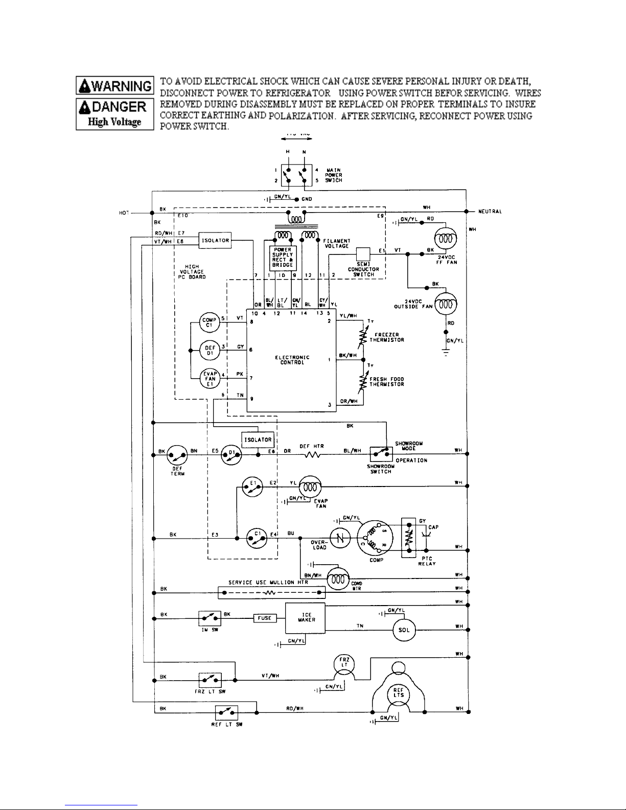
Wiring Diagram----------------------------------------------------------------------------------- 18
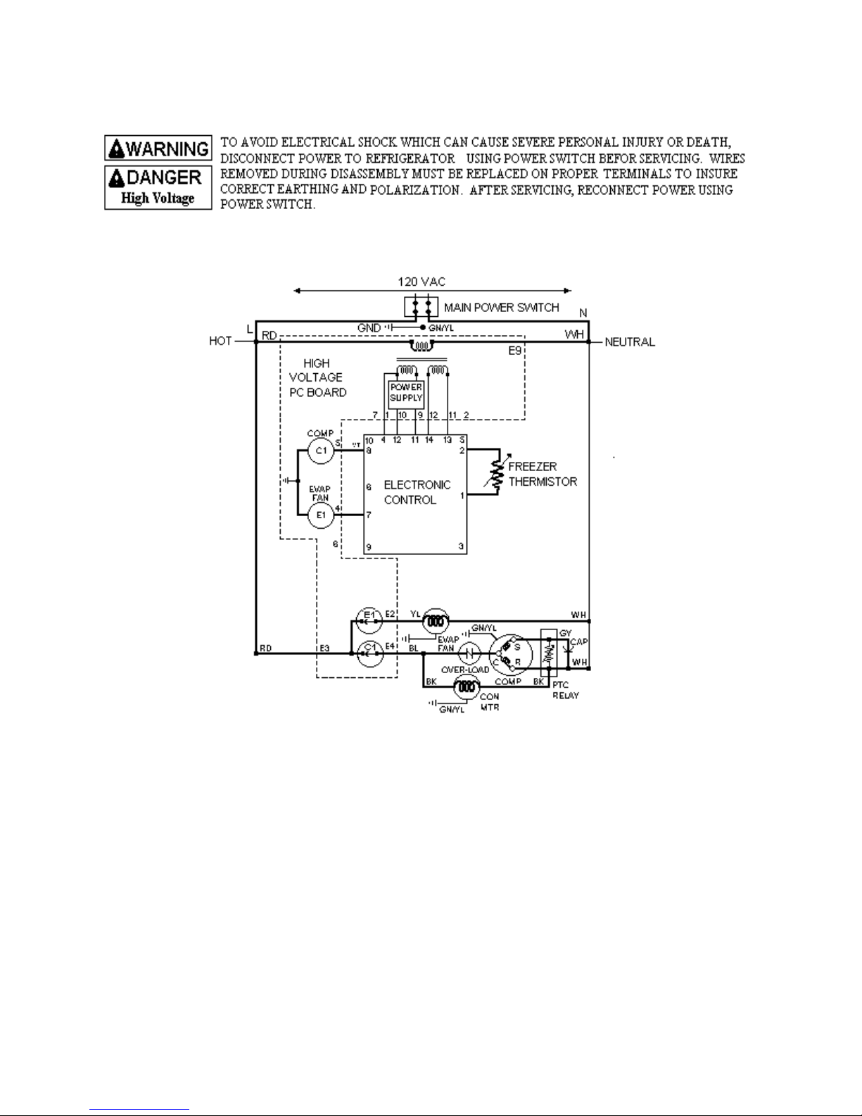
Freezer Compartment Theory of Operation--------------------------------------------------- 18
Wiring Diagram----------------------------------------------------------------------------------- 19
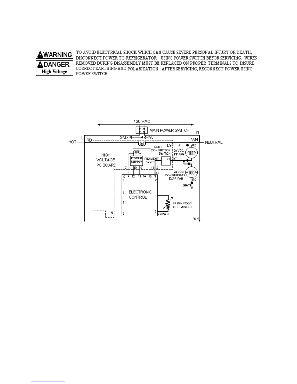
Refrigeration Compartment Theory of Operation-------------------------------------------- 19
Wiring Diagram----------------------------------------------------------------------------------- 20
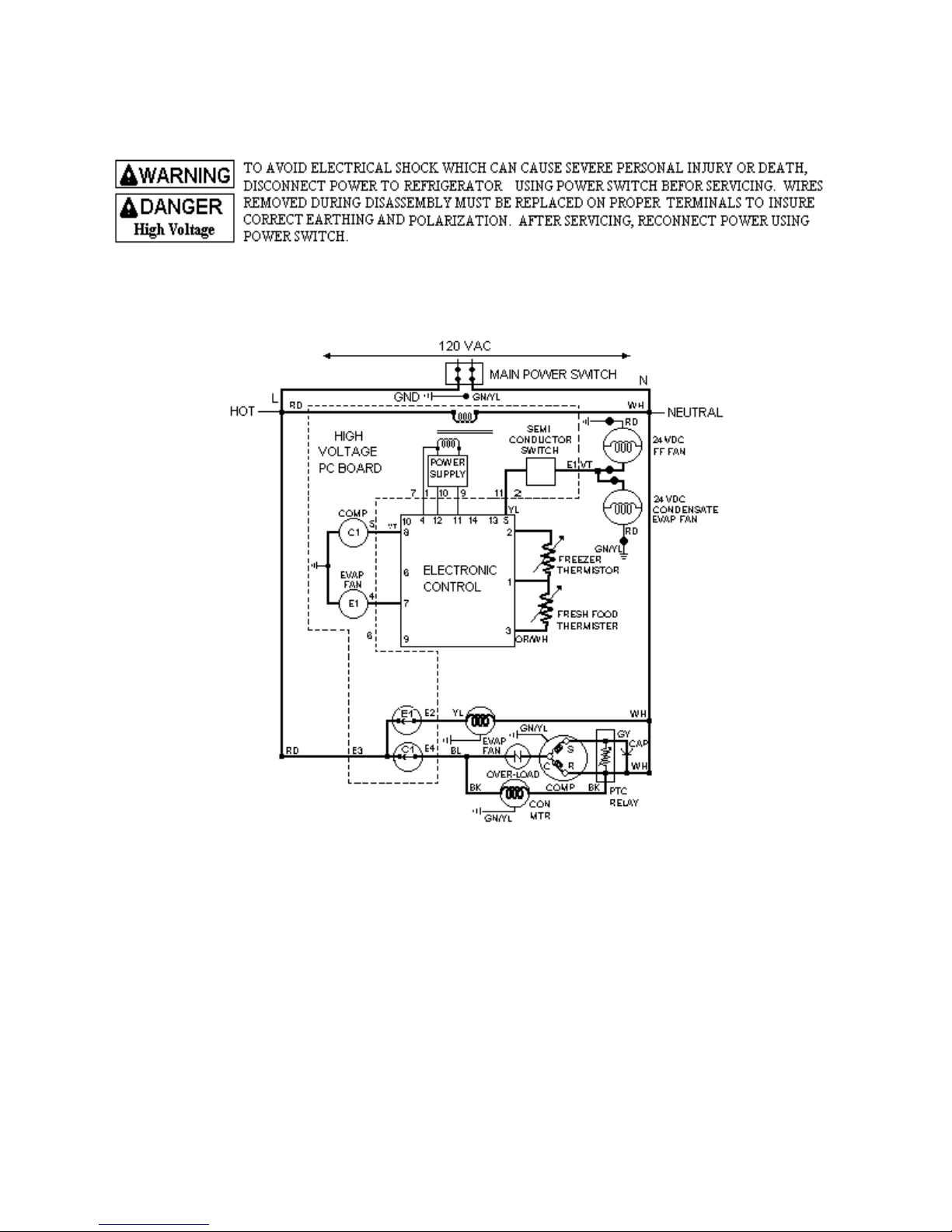
Refrigeration and Freezer Compartment Theory of Operation----------------------------- 20
Wiring Diagram----------------------------------------------------------------------------------- 21
Adaptive Defrost Theory of Operation-------------------------------------------------------- 21
Full Wiring Diagram----------------------------------------------------------------------------- 22
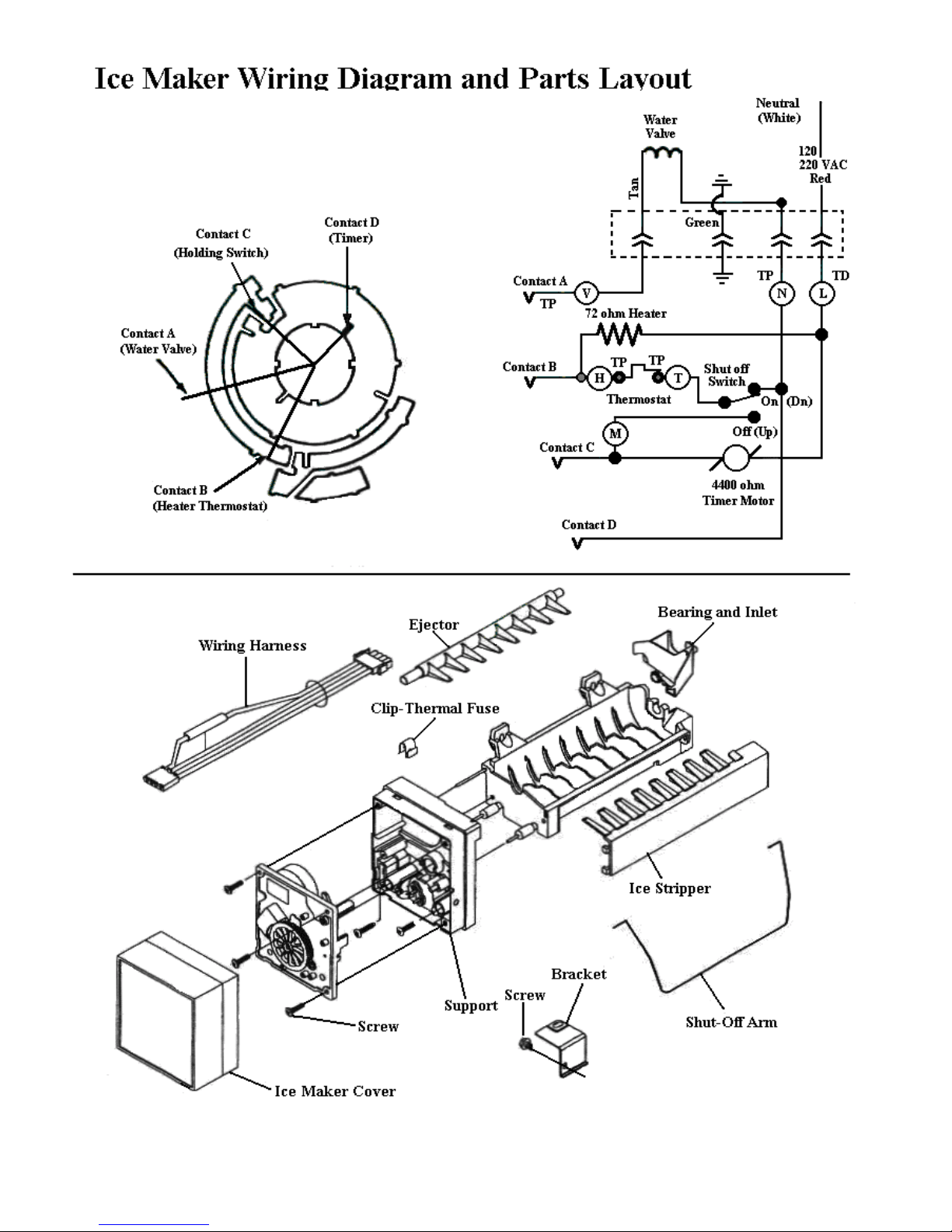
Ice Maker (Operation)--------------------------------------------------------------------------- 23
Ice Maker (Testing Procedures)---------------------------------------------------------------- 23
Ice Maker (Disassembly Procedures)---------------------------------------------------------- 24
Water Fill Valve Adjustment------------------------------------------------------------------- 25
Troubleshooting Chart--------------------------------------------------------------------------- 28
Ice Maker Wiring Diagram and Parts Layout------------------------------------------------ 32
3
Page 3
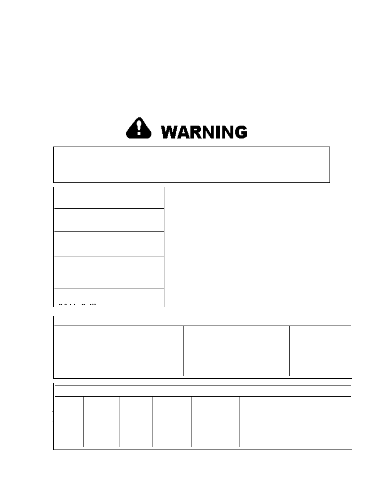
TECHNICAL INFORMATION
p
•••• Due to a possibility of personal injury or property damage, always contact an
authorized technician for servicing or repair of this refrigerator.
•••• Refer to Service Manual for design, disassemble, ice maker, safety, testing, and
troubleshooting information.
To avoid electrical shock which can cause severe personal injury or death, disconnect power to
the refrigerator using power switch before servicing. Wires removed during disassembly must be
replaced on proper terminals to insure correct earthing and polarization. After servicing,
reconnect
ower using power switch.
Model VCSB481SS
Capacity 28.57 cu. ft.
Electrical 120 VAC
Requirements 60 Hz
Separate Circuit 15 Amp
Refrigerant type 134A
Width 47 ½”
Depth 24”
Without Handle
Includes Door
Extrusions
Height Range 83 ¼” - 84
Rollers to Top
No Load Performance Controls in Normal Position
Kw /24 hr
±0.4
Percent Run
Time ±10%
Cycles /
24hr
±25%
Refrigerator
Center
Compartment
Food
Average
Temperature
Freezer
Compartment
Food Average
Temperature
±±±±3°F
Temperature Relationship Test Chart
°
Ambie
nt
T-1
Outlet
±3°F
65°
110°
T-2
Inlet
±3°F
65°
110°
T-3 Suction
Line
±7°F
65°
110°
Average Total
Wattage
±10%
65°
110°
Suction Pressure
±2 PSIG
65°
110°
Head Pressure
±5 PSIG
65° 110°
4
Page 4
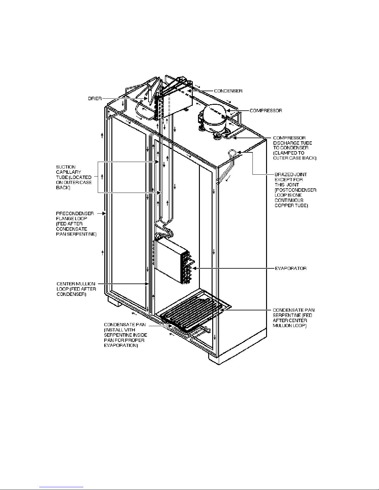
REFRIGERANT FLOW
5
Page 5
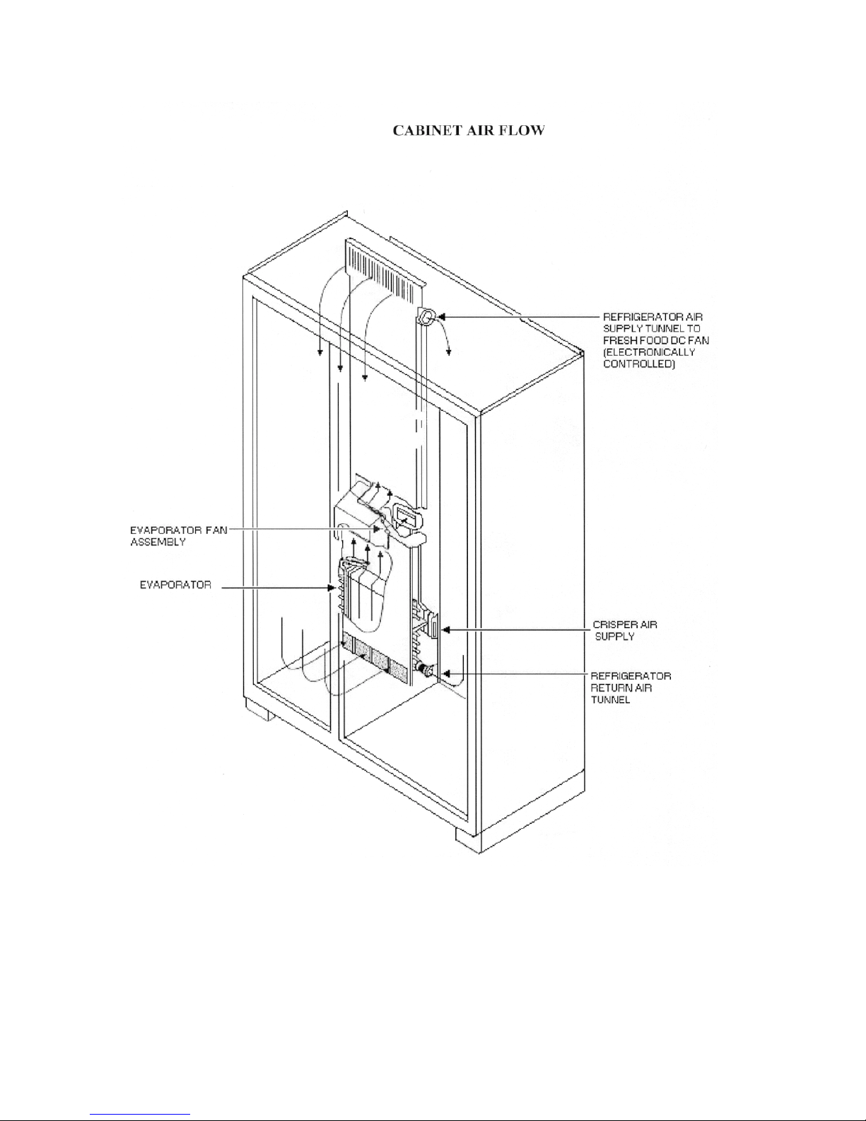
6
Page 6
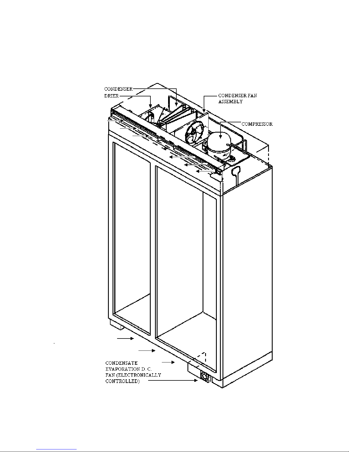
MACHINE COMPARTMENT AIR FLOW
7
Page 7
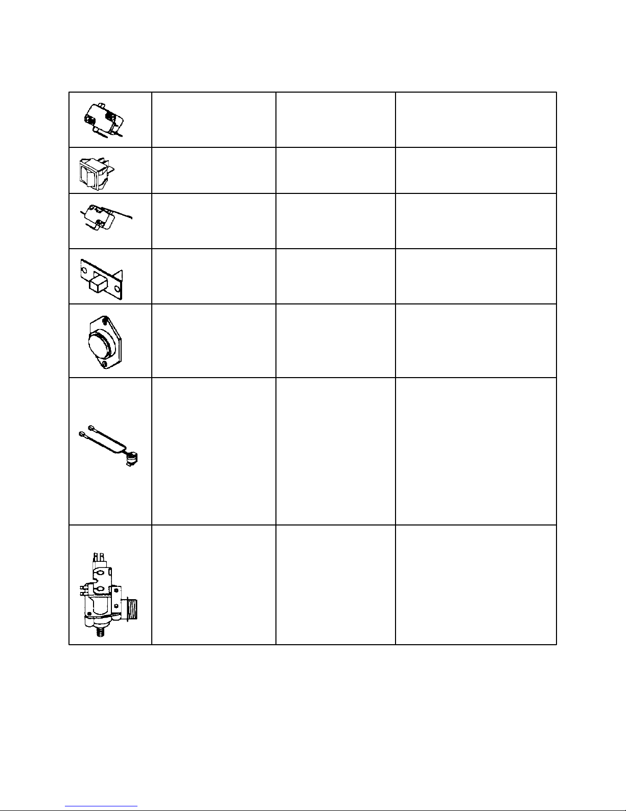
Component Specifications
Switch, refrigerator light Type SPST, NC
(Right opening door hinge) Volt 125 / 250 VAC
Current 3 Amps
Switch, power Type DPST
Volt 125 / 250 VAC
Current 15 Amps
Switch, freezer light, sealed Type SPST, NC
Volt 125 / 250 VAC
Current 5.0 Amps.
Switch, showroom Type SPDT
Volt 125VAC
Current 6 Amps
Thermister Check resistance across
Terminals. Bell curve
Resistance (see page 13)
@77°F 30,000 ohms ± 1% ohms
@45°F 68,000 ohms ± 2% ohms
Thermostat Volt 120VAC
Watt 1000 Watts
Current 10 Amps
Resistance across
Above 55°F ± 6°F Open
Below 20°F ± 8°F Closed
Between 55°F ± 6°F
And 20°F ± 8°F Will stay in current state (either
Open or closed) until either 55°F
± 6°F and 20°F ± 8°F is reached.
Valve, water Volt 120VAC, 60Hz.
Watt 20 Watts
Water pressure (inlet)
Max 120psi
Min 20psi
Fill rate 140 ± 10 CC’s at 7.5 seconds.
terminals
8
Page 8
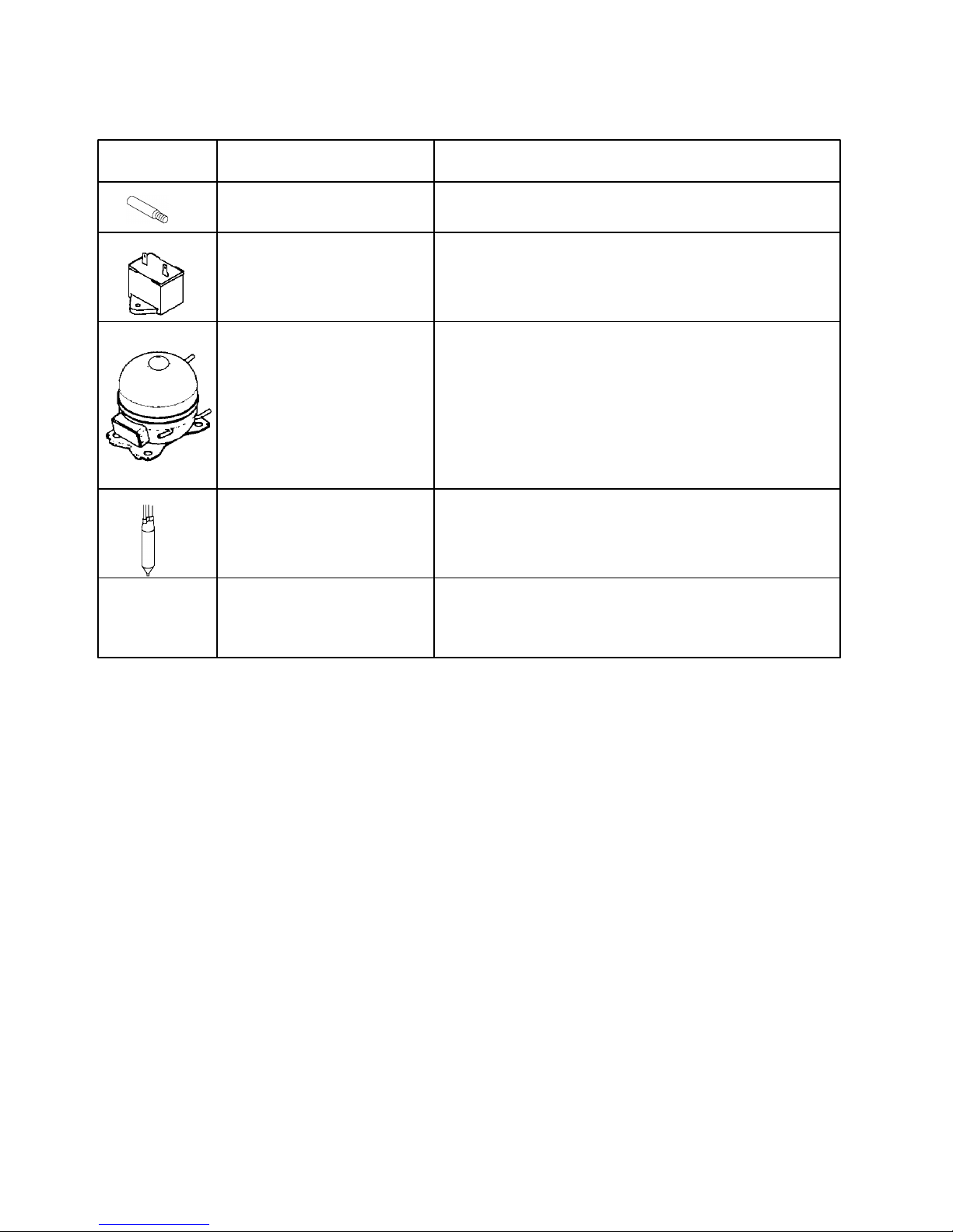
Component Specifications
Component Description Test Procedures
Bulb Volts 120VAC
Watts 40 watts
Capacitor, compressor run Volts 220VAC
Capacitance 15 µfc + 10%
- 5%
Compressor Type Fan cooled, R134a refrigerant
BTUH 970 BTUH
Volts 120VAC 60Hz
Watt 176 watts
Current: Lock rotor 21.3 A
Full load !.6 A
Resistance: Run windings 2.60Ω
Start windings 4.35Ω
Drier Drier must be changed every time the system is opened
for testing or compressor replacement.
Desiccant (20) 8x12.4AXH – 7 M. S.-Grams
Heater, evaporator Volt 120VAC
Wattage 450 ±5% W
Resistance 30 ± 5% Ω
8B
Page 9
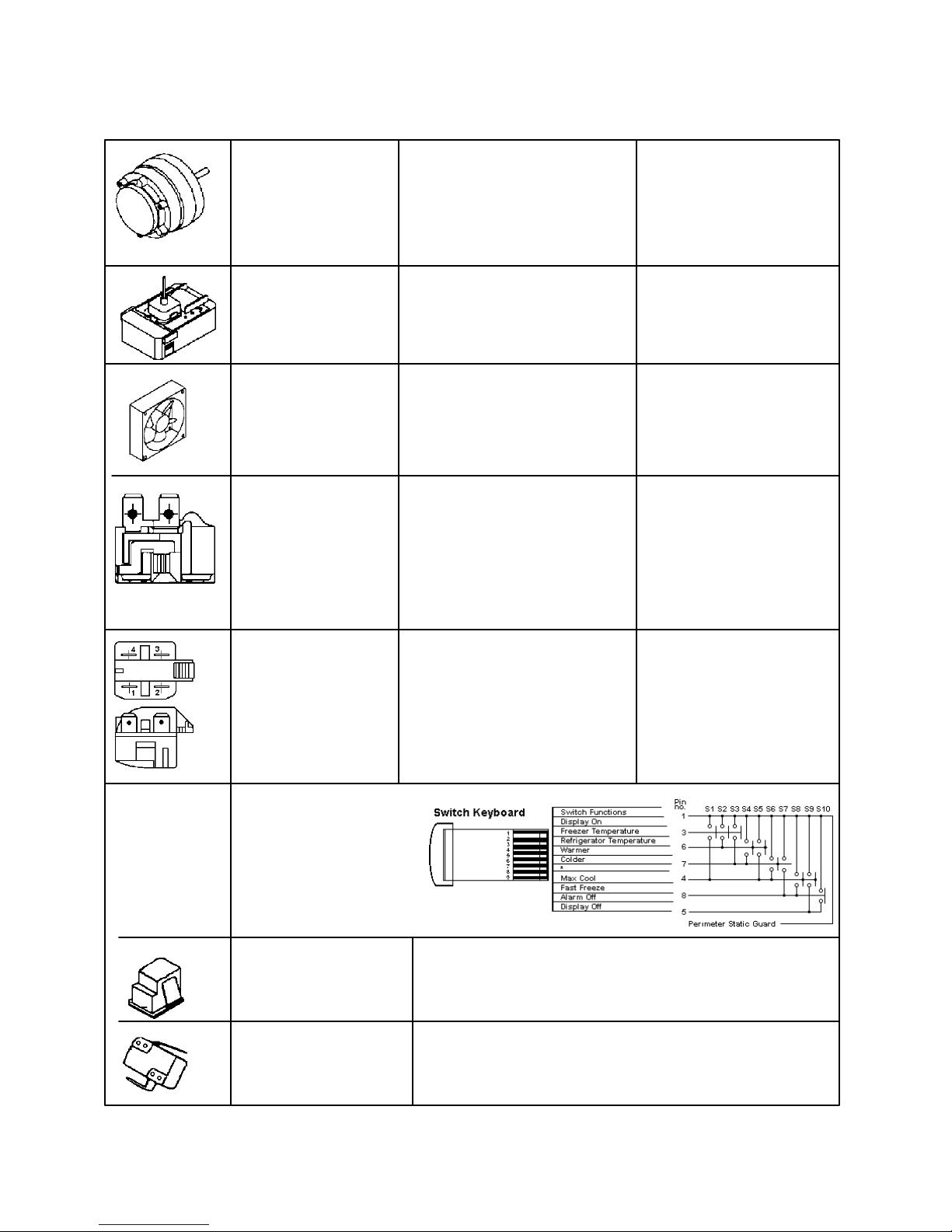
Component Specifications
Motor, condenser PSC Volt 120 VAC
Rotation (facing end opposite shaft) Clockwise
RPM 1300 RPM
Watt 6.4 Watts
Current 0.05 Amp
Resistance 480 Ω
Motor, ECM evaporator Volt 120VAC
fan. Rotation (facing shaft) Counterclockwise
RPM 2150 RPM
Watt 1.4 Watts
Motor and blade, Volt 120VAC
Refrigerator, condenser, Rotation (facing shaft) Counterclockwise
evaporator fan. RPM 3300 RPM
Watt 1.4 Watts
Overload Volt 120VAC
Ult. Trip amps @158°F (70°C) 3.51 Amps
Close temperature 142°F (61°C) ± 9°
Open temperature 257°F (125°C) ± 5°
Short time trip (seconds) 10 seconds
Short time trip (amps @ 77°F
(925°C) 14 amps.
Relay Resistance with power off check
across terminals 2 & 3. 3 – 12 Ω
Shorted 0 Ω
Open very high or infinite ohms.
Switch, auger Type DPST, NO
Volts 250 / 125 VAC
Current 10 / 5 Amp.
Switch, refrigerator light Type SPST, NC
(left opening door hinge) Volt 125 / 25 VAC
Current 3 Amps.
9
Page 10
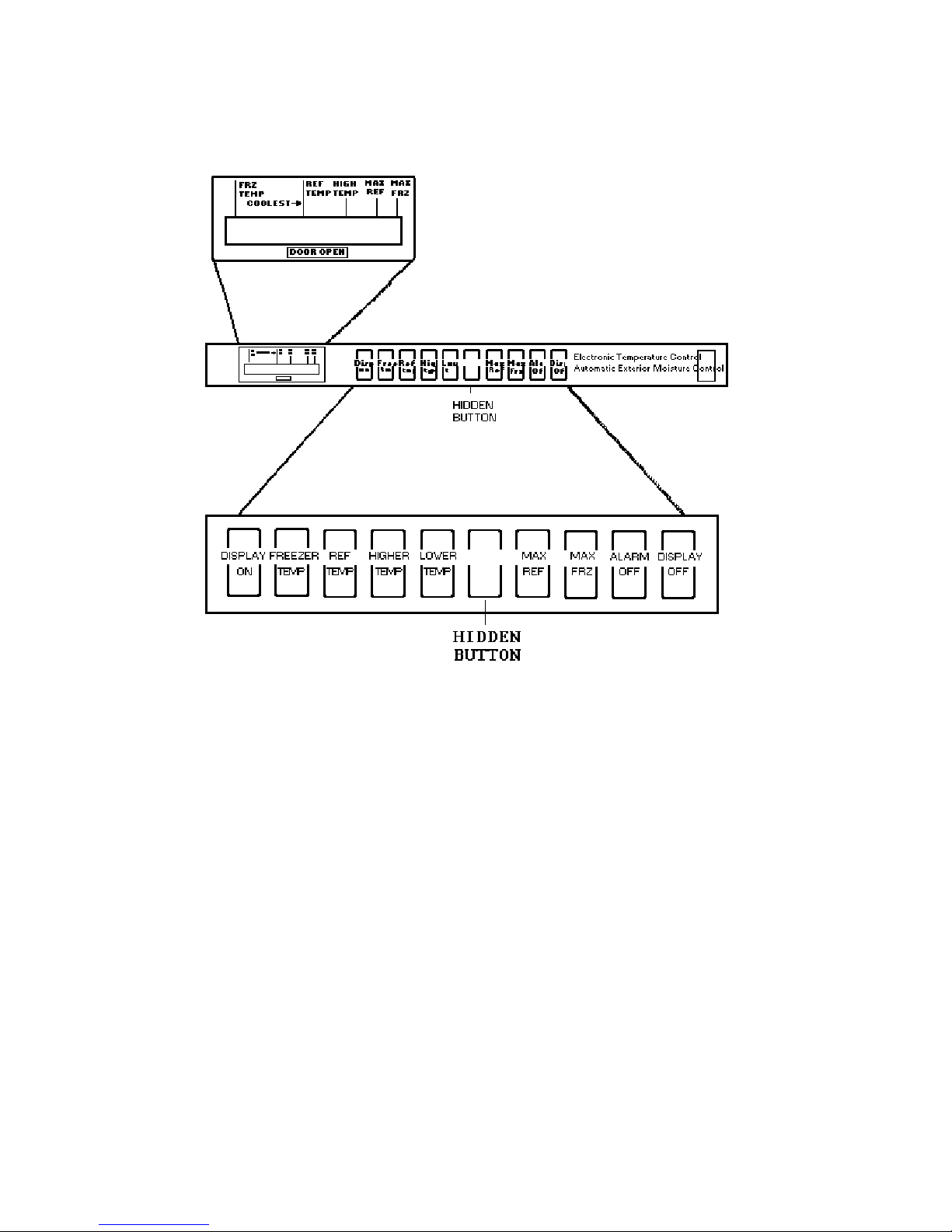
DISPLAY PANEL KEYBOARD
Display Panel Operation
Keyboard Pad Fu nctions
Entry Tone
Indicates a pad was pressed, command read and
accepted. Turn off entry tone by pressing and
holding Display On pad for 3 to 5 seconds.
Command Accepted Tone
Three short tones indicate command accepted.
Display On Pad
1. Activates control panel. Control panel
remains active at least 10 minutes.
2. Turns off Power Up Alarm (flashing lights)
after power is first plugged in or after power
outage.
Note: All pads, except Alarm Off, are inactive
until Display On is pressed.
Freezer Temp Pad
Activates freezer temperature setting mode.
1. Freezer indicator light will glow. Freezer
temperature setting will be displayed.
Factory setting is 5.
2. Change freezer temperature setting by
pressing Higher Temp or Lower Temp Pad.
Ref Temp Pad
Activates refrigerator temperature setting mode.
1. Refrigerator indicator light will glow.
Refrigerator temperature setting will be
displayed. Factory setting is 5.
2. Change refrigerator temperature setting by
pressing Higher Temp or Lower Temp Pad.
Higher Temp Pad
Raises temperature setting one bar at a time. If
entry tone is on. Tone will sound at each bar
level until top level is reached.
1. Turn on temperature setting function of
control panel by pressing Higher Temp Pad.
2. Press and hold Higher Temp pad to raise
temperature setting at a faster rate.
10
Page 11
Display Panel Operation (con’t)
Lower Temp Pad
Lowers temperatures setting one bar at a time. If
entry tone is on, tone will sound at each bar level
until bottom level is reached.
1. Turn on temperature setting function of control
panel be pressing Lower Temp Pad.
2. Press and hold Lower Temp Pad to lower
temperature setting at a faster rate.
Max Frz Pad
Activates Maximum freezer mode setting freezer
temperature to coldest setting for 24 hours or until
Max Frz pad is pressed again.
1. Freezer indicator light will glow.
2. To adjust maximum freezer mode time refer to
Program Mode B functions.
Max Ref Pad
Activates Maximum refrigerator mode setting
refrigerator to coldest setting for 24 hours or until
Max Ref Pad is pressed again.
1. Refrigerator indicator light will glow.
2. To adjust maximum refrigerator time refer to
Mode B functions.
Alarm Off Pad
Turns off alarm signals. See Alarms section to
interpret alarm signals.
1. Press and hold Alarm Off pad for 3 seconds to
deactivate Door Open alarm. To reactivate Door
Open alarm, press and hold Alarm Off pad for 3
seconds.
2. If Alarm Off pad is pressed and condition
causing alarm is not corrected, alarm will reset.
Hidden Button
Activates Program Mode. See Program Mode
section for description of functions available.
1. Open refrigerator door.
2. Press Display On pad.
3. Press hidden button pad.
4. Within 6 seconds press the following pads in this
sequence: Max Ref, Max Frz, Max Ref, Max
Frz.
5. Tone will sound 3 times and control will be in
program mode A.
Display Off Pad
1. Deactivates control panel.
2. Deactivates temperature indication area of
control panel.
Electronic Functional Description
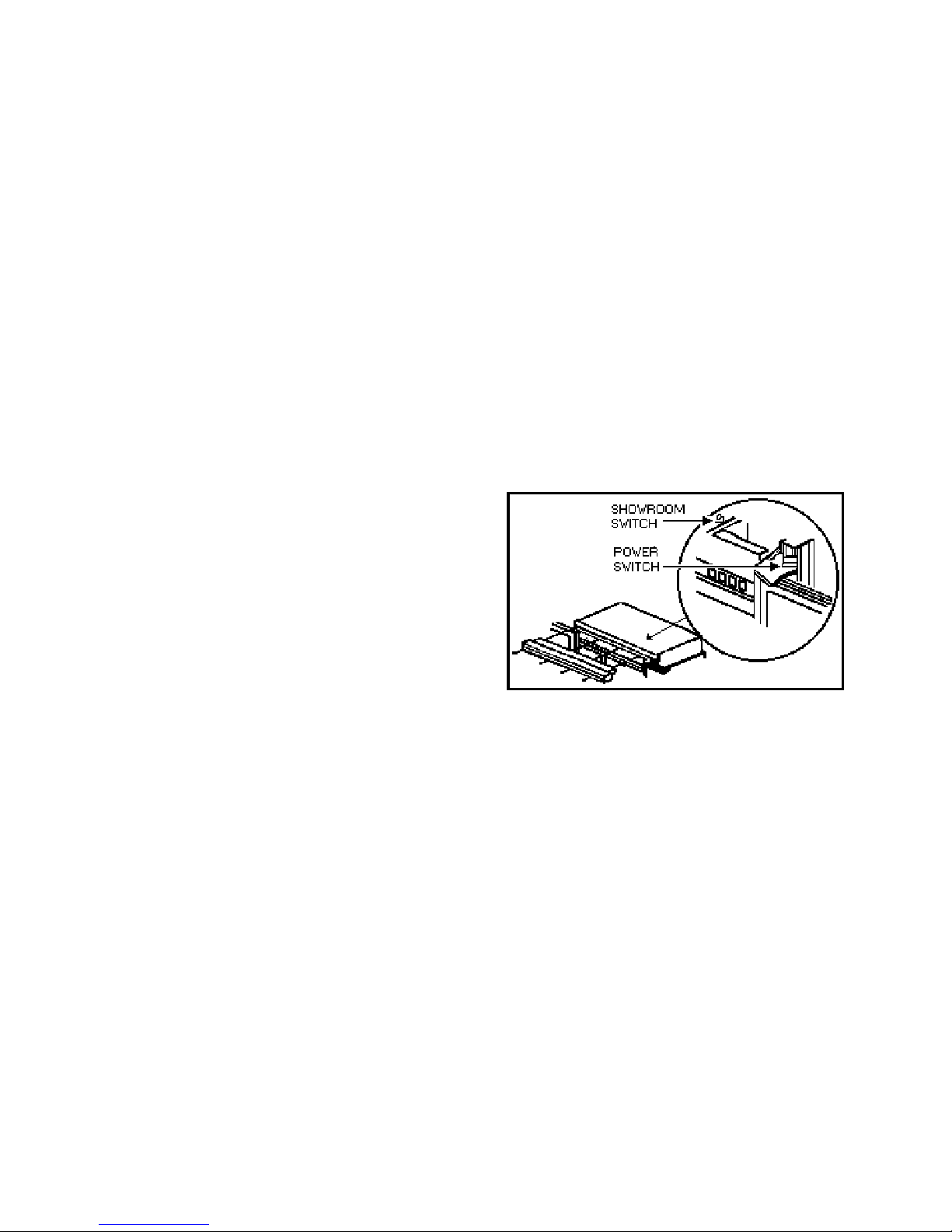
Power Disconnect Switch
Use power disconnect switch to disconnect power
without unplugging refrigerator. Power disconnect
switch is located behind air grille on top right side.
Refrigerator is shipped with power disconnect switch
in the On position.
Showroom Switch
Showroom switch allows electronic controls and
interior lights to function independently of
refrigeration system. Showroom switch is located
behind air grill to right of control panel. Refrigerator
is shopped with showroom switch in unit run
position.
Alarms
Power Up Alarm
After power is initially plugged in, after a power loss,
or if power switch is turned off, all temperature
indicator lights will flash until Alar m Off or Display
On is pressed.
Note: All settings return to default factory settings.
Door Open Alarm
Alarm tone sounds and indicator lights blink if either
refrigerator or freezer door is open more than 3
minutes.
1. Turn off Door Open alarm by pressing Alarm
Off pad or by closing door.
2. Deactivate door open alarm by pressing Display
On pad and then press and hold Alarm Off pad
for 3 seconds.
3. Door alarm delay can be adjusted in Program
Mode B.
High Temperature Alarm
Alarm sounds and indicator light shows if freezer or
refrigerator temperature has gone above critical level
and remained warm for 2 hours. Alarm tone stops if
temperature falls again.
11
Page 12

Electronic Functional Description (con’t)
1. Critical temperature for freezer is +15° F; for
refrigerator critical temperature is +60° F.
2. Press Alarm Off pad to turn off alarm.
Thermistor Alarm
Alarm sounds and freezer or refrigerator indicator
light shows and temperature indicators 4 through 7
will turn on in sequence if either thermistor circuit
opens. Refer to Temperature Control Operation
Section and Electronic Testing Section.
1. Press Alarm Off pad to turn off alarm.
2. Alarm will retest for normal operation. If
condition has not been corrected, alarm will
sound again.
Temperature Control Operation
For any temperature setting, outputs will be turned
off/on based on cut-in/cut-out temperature
determined by resistance levels of freezer and
refrigerator thermistors.
Refrigerator and Freezer Thermistor
As temperature decreases, resistance increases.
As temperature increases, resistance decreases.
Open thermistor or thermistor circuit will result in
failure of refrigerator to cool.
Shorted thermistor will cause refrigerator to run 100
percent of time except for defrost cycle.
• Freezer te mperature setting and thermistor value
will determine if compressor/condenser fan and
evaporator fan switches are open or closed.
Compressor/c ondenser fan switch must be open
for 6 minutes before switch can close again
(compressor dwell time).
• Refrigerator temperature setting and thermistor
value will determine if fresh food fan switch is
open or closed.
• Cut-out and cut-in temperature values must be
reached and maintained for 15 seconds before
output state will change (digital delay).
• Refrigerator and freezer control calibration can
be adjusted in Program Mode B.
Factory set freezer and refrigerator settings
12
Page 13
Electronic Functional Description (con’t)
Adaptive Defrost Operation
Defrost occurs after predetermined length of
compressor run ho urs. Co mp resso r run t ime b et ween
defrosts changes, or adapts, depending upon recent
history of defrost lengths (time it takes for defrost
terminator to open after defrost heater has been
turned on).
• Defrost terminator opens at 55° F (13° C) and
closes at 20° F (-7° C).
• Compressor run time between defrost (CRTD)
will be one of 3 values under normal operation:
CRTD 1 (8 hours) or CRTD 2 (12 hours) or
CRTD 3 (16 hours).
If defrost length is low (DT-LO defined as 21
minutes) indicating small frost load, CRTD for
next defro s t cycle is advanced to next level.
If defrost length is high (DI-HI defined as 24
minutes) indicating large frost load, CRTD for
next defro s t cycle is lowered to next level.
If defrost length is between 21 and 24 minutes,
CRTD for next defrost cycle remains the same.
Initial value at power up CRTD 0 is 4 hours.
• Hidden Button Mode CRTD equals 96 hours.
Hidden Button Mode CRTD is interrupted with
door openings. Defrost interval will revert back
to interval before Hidden Button Mode. Three
things must occur to reach Hidden Button Mode
CRTD:
1. Defrost interval must be CRTD 3 (16 hours).
2. Both refrigerator and freezer doors must
have remained closed since last defrost
cycle.
3. Defrost thermostat must have opened in less
than 21 minutes during last defrost cycle.
• Six minutes dwell time occurs after defrost
terminator opens before compressor and
condenser fan motor will operate. Ten minute
dwell time occurs after defrost terminator opens
before evaporator fan motor will operate. Dwell
time can be bypassed by disconnecting power to
the unit for 30 seconds.
• Conventional defrost can be selected in Program
Mode B.
PROGRAM MODE
Accessing Program Mode
Two programming modes are available. Mode A
allows
reading refrigerator and freezer thermistor
temperatures. Mode B is used for all odther
programmable functions.
1. Open refrigerator door.
2. Press Display On pad.
3. Press Hidden Button pad.
4. Press the following sequence of pads within 6
seconds; Max Ref, Max Frz, Max Ref, Max frz.\
5. When access is granted, tone will sound three
times and control will be in Program Mode A.
unmarked indicator light will illuminate.
6. Toggle to Program Mode B be pressing Display
On pad. Unmarked indicator light is off.
EEPRM Update in Control Memory
EEPRM is permanent programmable memory of the
control pane..
• Entry tone, door audio alarm and status are
stored in EEPRM after control panel is
deactivated.
• Information stored in EEPRM memory is not
affected by power loss.
Mode A Functions
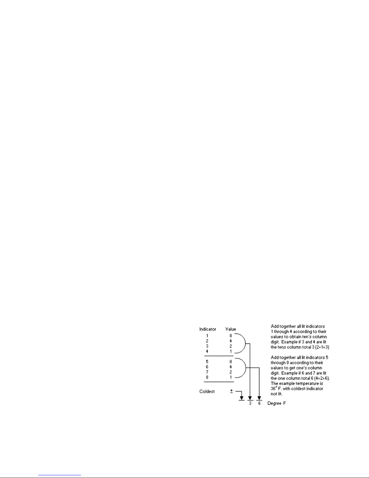
Reading Temperature Display
Temperature display will show thermistor
temperature in binary coded decimal format (BCD).
Indicator lights 1 through 4 represent the tens digit
with 1 being the most significant bit. Indicator lights
5 through 8 represent ones digit with 5 being the
most significant bit. Positi ve and negative are sho wn
be indicator light 9; light glows to show negative
value.
13
Page 14
Mode A Functions (con’t)
Freezer Thermistor Temperature
1. Choose freezer thermistor temperature display by
pressing Freezer Temp pad.
2. Freezer thermistor temperature displays.
Refrigerator Thermistor Temperature
1. Choose Refrigerator Thermistor temperature
display by pressing Ref Temp pad.
2. Refrigerator thermistor temperature displays.
Mode B Functions
Automatic Keyboard Functions
Activate and deactivate keyboard by toggling Display
Off pad. If high temperature indicator glows,
keyboard will disable after 10 minutes. If high
temperature indicator is off, keyboard is always
enabled. DO NOT LEAVE KEYBOARD IN
ENABLED MODE AFTER PROGRAMMING IS
COMPLETE
Door Alarm Delay
1. Press Alarm Off pad. Door open indicator will
glow. One temperature indicator should glow
indicating present delay setting in minutes
(indicator 1 means 1 minute, 2 means 2 minutes,
etc.) Default delay is 3 minutes.
2. Press Higher Temp pad to decrease delay by 1
minute.
3. Press Lower Temp pad to increase delay by 1
minute.
Max Ref Run Time Duration
1. Press Max Ref pad. Max Ref light will glow.
One temperature indicator should glow
indicating present Max Ref run time duration in
2 hour incre ments (indicato r 1 means 2 hours, 2
means 4 hours, etc.) Defa ult delay is 1 0 hours.
2. Press Higher Temp pad to decrease Max Ref
duration by 2 hours.
3. Press Lower Temp pad to increase Max Ref
duration by 2 hours.
Max Frz Run Time Duration
1. Press Max Frz pad. Max Fra light will glow.
One temperature indicator should glow
indicating present Max Frz run time duration in 4
hours increments (indicator 1 means 4 hours, 2
means 8 hours, etc.) Defa ult delay is 2 4 hours.
2. Press Higher Temp pad to decrease Max Frz
duration by 4 hours.
3. Press Lower Temp pad to increase Max Frz
duration by 4 hours.
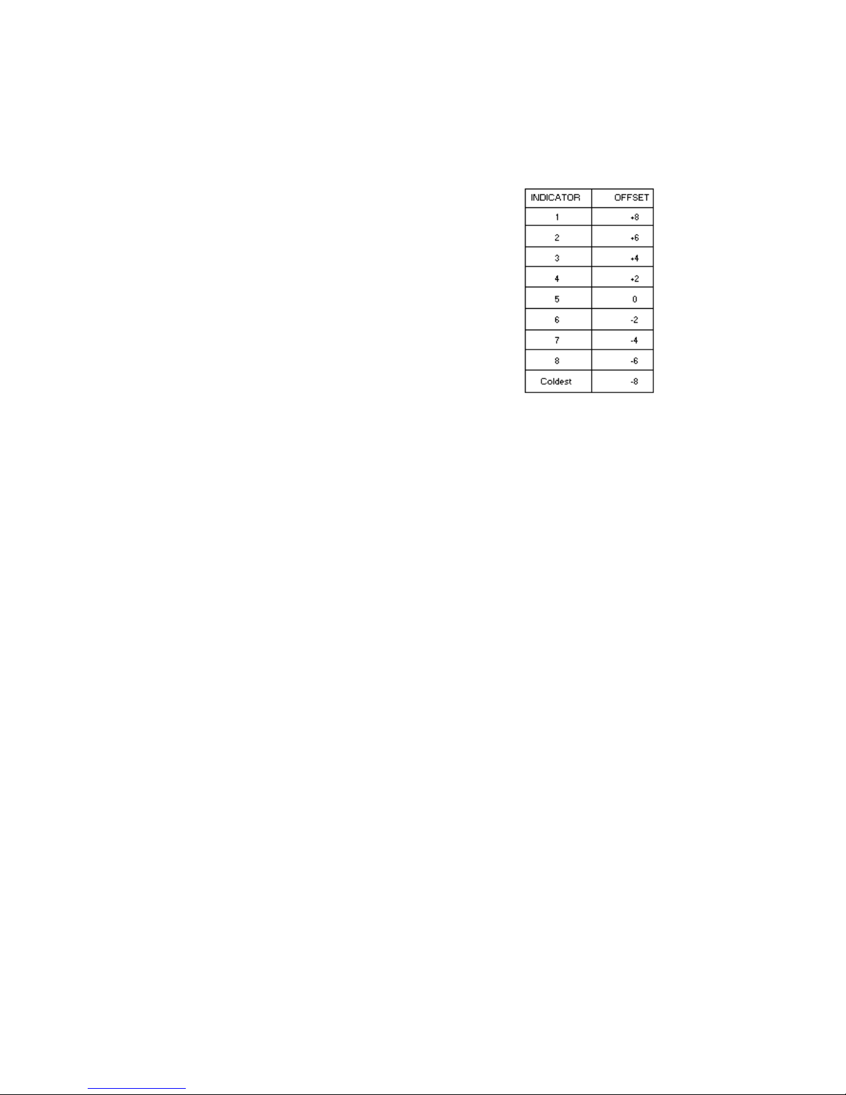
Temperature Offset Calibration
Offset amount adjusts temperatures for refrigerator
cut-ins and cut-outs by the amount of offset. The
chart below shows the indicator and the amount of
offset from the factory default setting.
• Setting Refrigerator Temperature Offset
Press Ref Temp pad. Refrigerator indicator and
one indicator will glow. Press Higher Temp pad
to move offset to the next warmer setting. Press
Lower Temp pad to move offset to the next
colder setting. Factory default refrigerator offset
is –4.
• Setting Freezer Temperature Offset
Press Freezer Temp pad. Freezer temperature
indicator and one indicator will glow. Press
Higher Temp pad to move offset to the next
warmer setting. Press Lower Temp pad to move
offset to the next colder setting. Factory default
freezer offset is 0.
Defrost Mode Selection
Toggle Hidden Button pad to select adaptive or
conventional defrost mode. Hidden Button indicator
glows when adaptive defrost has been selected. If
Hidden Button indicator is off, conventional defrost
is selected. Conventional defrost uses 8 hour CRT D
value.
Forced Defrost
Defrost can be forced to start by pressing and holding
the Alarm Off pad for 3 seconds. Program changes
will be saved permanently in EEPROM and program
mode will exit to Run Mode.
Forced Pull Down
Compressor start can be forced by pressing and
holding Max Frz pad for 3 seconds. Program
changes will be saved permanently in EEPROM.
Compressor, evaporator fan and condenser fan will
come on.
14
Page 15

Exiting Program Mode
Press Display On pad for 3 seconds to exit Program
Mode. Tone will sound three times. Changes made
in Program Mode will be permanently saved in
EEPROM.
Note: If no pad is pressed for 10 minutes, Program
Mode will be automatically exited. However, no
changes will be saved if Program Mode exits
automatically.
Electronic Testing
Electronic Testing Mode
Forced Defrost Start
1. Press Display On pad to activate control panel.
2. Simultaneously press and hold Max Ref and
Display Off pads for 3 seconds.
Forced Compressor Start
1. Press Display On pad to activate control panel.
2. Simultaneously press and hold Max Frz pad and
Display Off pad for 3 seconds.
Open Thermistor Detect
Alarm sounds and freezer or refrigerator indicator
light shows and temperature indicators 4 through 7
will turn on in sequence if either thermistor circuit
opens. Refer to Temperature Control Operation
Section and Electronic Testing Section.
1. Press Alarm Off pad to turn off alarm.
2. Alarm will reset for normal operation. If
condition has not been corrected, alarm will
sound again.
15
Page 16
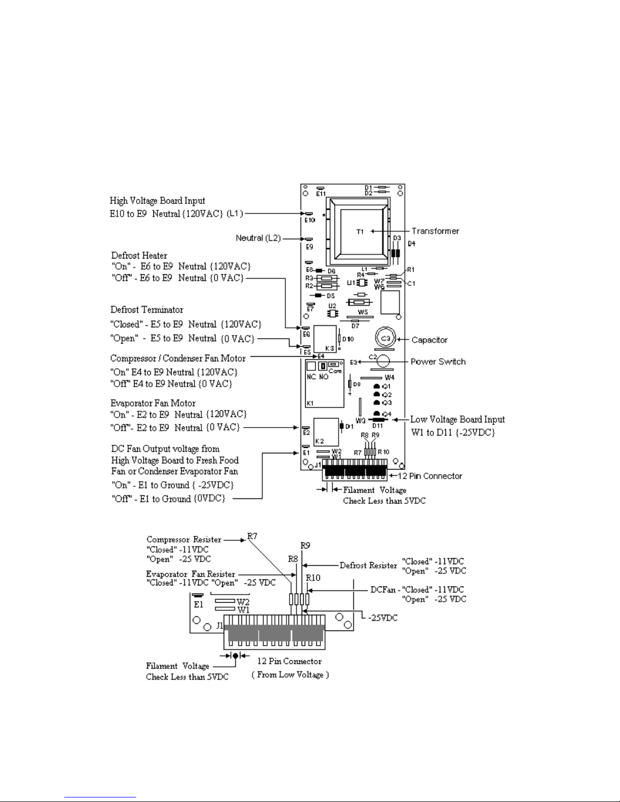
Electronic Functional Description
WARNING: TO AVOID ELECTRICA L SHOCK WHICH CAN CAUSE SEVERE INJURY OF D EATH,
DISCONNECT POWER TO REFRIGERATOR USING POWER SWIDTCH BEFORE SERVICING.
WIRES REMOVED DURING DISASSEMBLY MUST BE REPLACED ON PROPER TERMINALS TO
INSURE EARTHING AND POLARIZATION. AFTER SERVICING, RECONNECT POWER USING
POWER SWITCH.
16
Page 17
17
Page 18
Electronic Function Description
Freezer Compartment Theory of Operation
As a freezer thermistor warms, the resistance
decreases allowing low voltage signal to be sent to
electronic control. Electronic control sends two low
voltage signals, one to the compressor rela y coil )C1)
and one to the evaporator relay coil (E1).
When both relay coils are energized and
both relay contacts are closed, high voltage
circuits to evaporator fan motor and
compressor / condenser fan motors are
complete.
18
As thermister cools during refrigeration
cycle, resistance through thermistor
increases blocking low voltage signal to
electronic control interrupting circuit.
Page 19
Electronic Function Description
Refrigeration Compartment Theory of Operation
As fresh food thermistor warms, resistance decreases
allowing low voltage signal to be sent to the
electronic control. Electronic control sends a low
voltage signal to semiconductor s witch for DC fresh
food fan and DC condensate evaporator fan.
Both fans begin operating. Fresh food fan circulates
freezer air into fresh food compartment. Condensate
evaporator fan circulates air over condensate drain
pan aiding in evaporation.
As fresh food thermistor cools, resistance increases
blocking low voltage signal to electronic control
interrupting circuit to DC fresh food fan and DC
condensate evaporation fan.
19
Page 20
Electronic Function Description
Refrigerator and Freezer Compartment theory of
Operation
If both freezer and fresh food thermistors are warm,
their resistance drops (see table Refrigerator and
Freezer Thermistor in Temperature Control Section)
and the electronic signals for compressor / condenser
fan motor operation and for operation of fresh food
and condensate evaporator fans.
After freezer thermistor cools sufficiently to raise
resistance and block the signal to the electronic
control, compressor / condenser fan motor will shut
off.
20
However, fresh food and condensate evaporator fans
will continue to run until fresh food thermistor cools
and signal is blocked to electronic control.
If fresh food thermistor cools before freezer
thermistor, electronic control will interrupt circuit to
fresh food and condensate evaporator fans while
evaporato r fan motor will conti nue to operate under
control of freezer thermistor.
Page 21
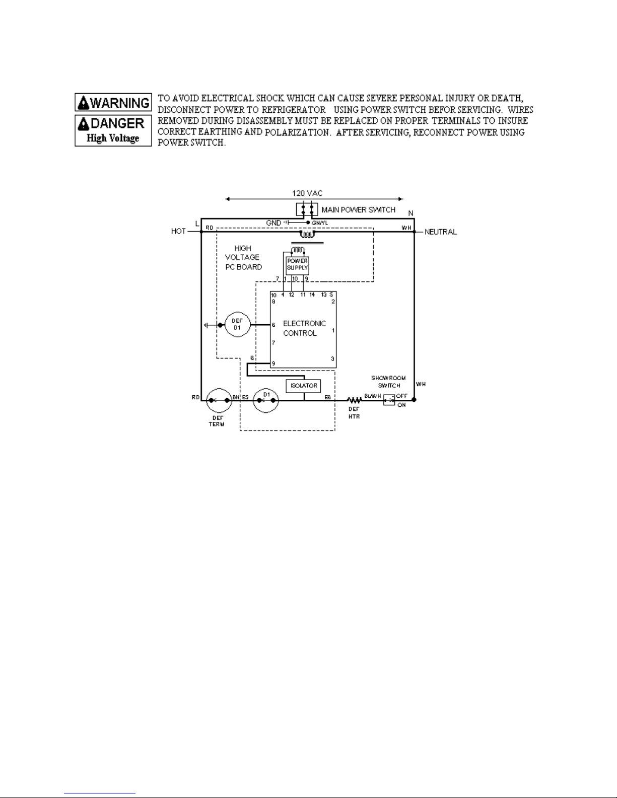
Electronic Function Description
IMPORTANT: When the showroom switch is OFF, the isolator sees line voltage which keeps the electronic
controller from signaling the evaporator fan motor or compressor relay coils and keeps the fresh food and
condensate evaporator fans off.
Adaptive Defrost Theory of Operation
After designated compressor run time, refrigeration
cycle is interrupted and electronic control sends a low
voltage signal to defrost relay coil (def D1).
Powering the relay coil closes contact (D1)
completing high voltage circuit to defrost heater
through closed defrost terminator (closes at 15°F).
Isolator, which is part of high voltage PC board,
recognizes presence of line voltage to defrost heater
and sends low voltage signal to electronic control..
Electronic control keeps count of number of minutes
defrost terminator remains closed (opens at 48°F).
Length of time defrost terminator is closed
determines if the next defrost cycle advances by 4
hours of compres sor run, stays at the same inter val,
or delays be 4 hours of compressor run.
If defrost terminator does not open before 29
minutes, defrost cycle is automatically terminated by
electronic control and refrigeration cycles will
resume after 6 minutes dwell time.
21
Page 22
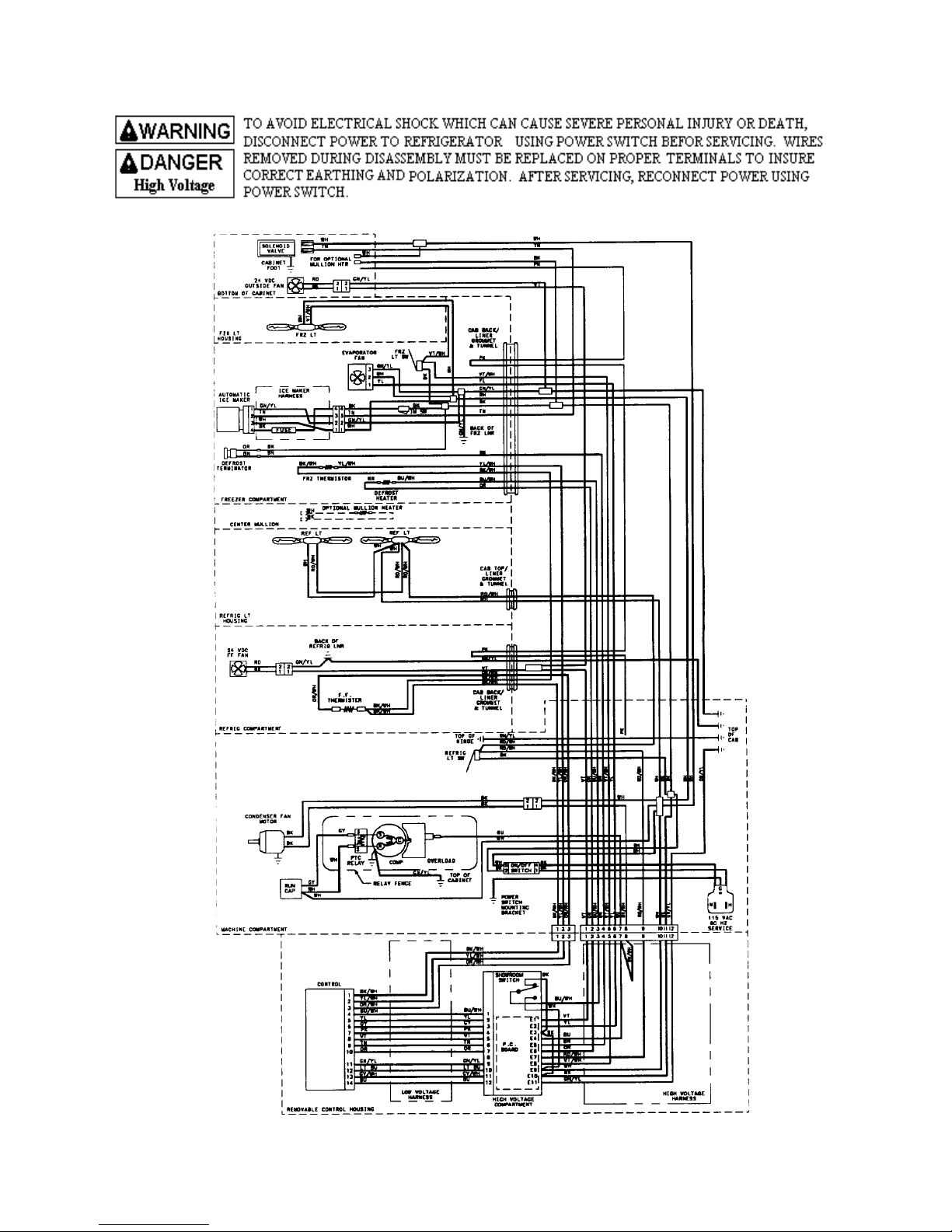
22
Page 23
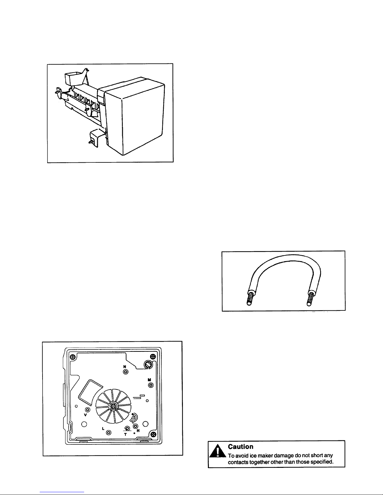
ICE MAKER
Operation
Thermostat closes when temperature reaches 17° ±
3°F (-8.3° ± 1.5°C). Current flows through
thermostat to motor. See “Ice Maker Wiring
Diagram”. Motor is linked with drive gear. From
module, there are copper contacts that ride on copper
strips on backside of drive gear. As the drive gear
rotates, contacts will make or break a circuit (tract) to
the copper strips to operate ice maker.
All components can be tested without removing ice
maker or movi ng refriger ator away fro m installat ion.
Remove cover.
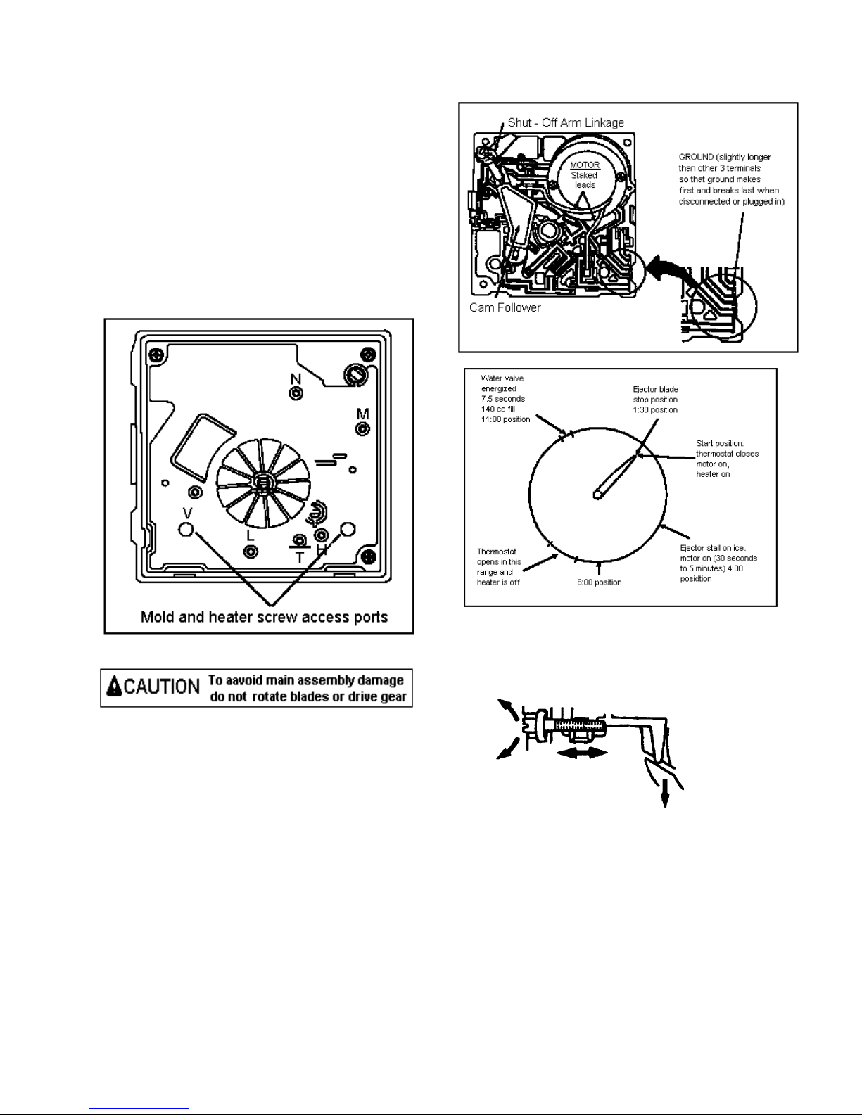
Test points are identified on module:
N = Neutral side of line
M = Motor connection
H = Heater connection
T = Thermostat connection
L = L1 side of line
V = Water valve connection
Specifications
Mold heater: 185 watts, 264 ohms
Thermostat: Close 17 ± 3° F (-8 ± 1° C)
(Bimetal) Opens 32 ± 3° F (0 ± 1° C)
Water fill: 140 cc, 7.5 sec.
Motor cycle Stamped in circuit.
Plug in connectors
One revolution of blades takes
3 minutes plug stall time on ice
(eject and water fill)
Testing Procedures
Verify ice maker has power, shut off arm is down,
and freezer is cold enough to close bimetal
thermostat.
• Test point L and N will verify 120 volts to ice
maker module.
• Test point T and H will verify bimetal
thermostat is open or closed.
• Verify test probes go into test points ½
inch (1.25 cm).
1. Short T and H with a sh unt (insulated
14 gauge wire with ends stripped back
5/8 inch (1.6 cm) to run motor. If
motor runs. Replace bimetal
thermostat. If motor does not run,
replace module.
2. Leave jumper in for half of revolution.
Touch heater mold. If heater mold
feels warm, heater is working properly
3. Remove jumper. Water valve will be
energized in last half of revolution if
mold heater has not failed.
23
Page 24
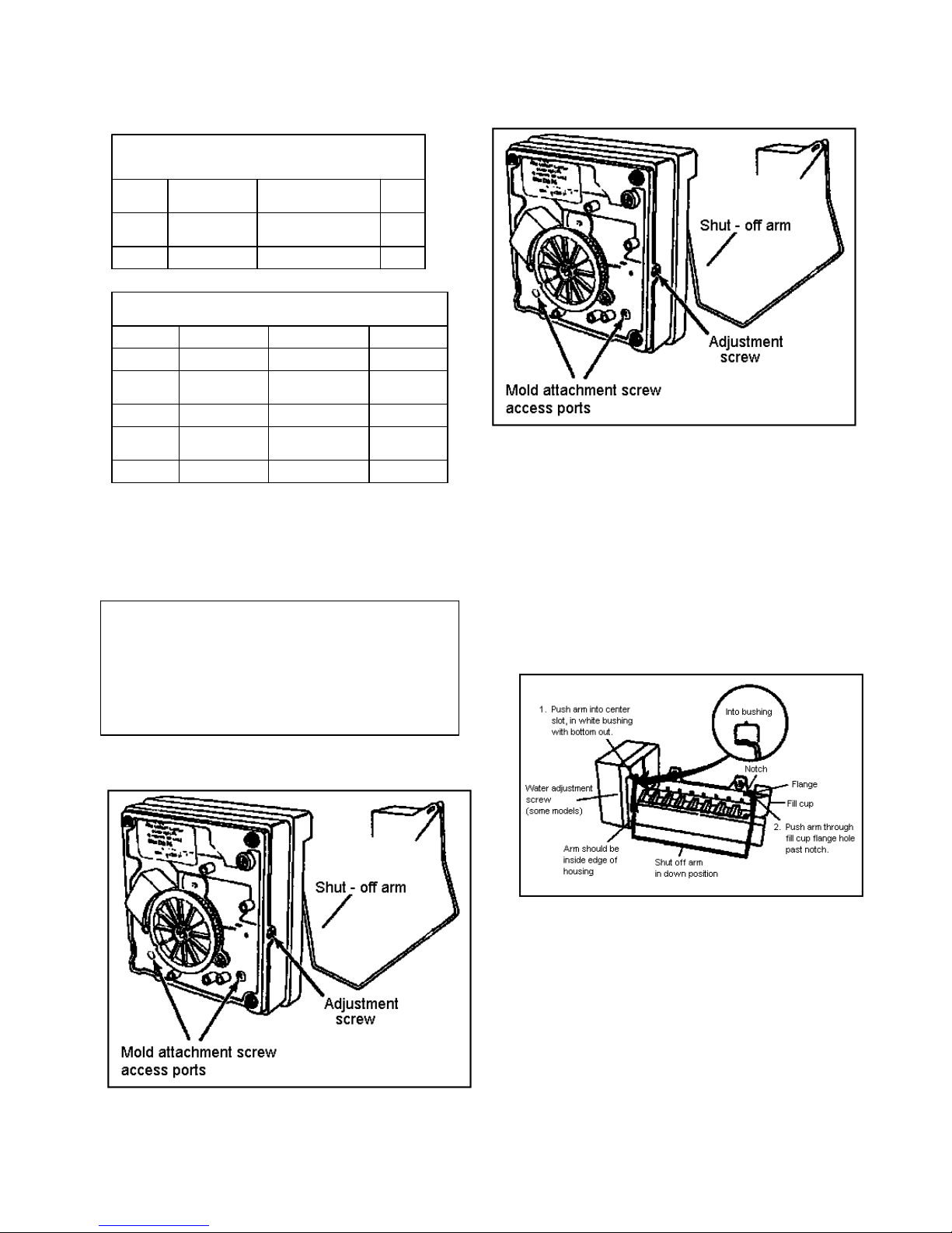
Ice Maker
Module Ohmmeter Check
No power to Ice Maker and
Ejector Blades in End of Cycle Position
Test Points Component Module Position Ohms
L-H Mold & Heater Attached to Support 264
L-M Motor Separated form Heater 16,100
Module Voltage Checks with Meter or Test Light
Power to Ice Maker
Test Points Component Line Voltage 0 Volts
L-N Module Power On Power Off
T-H Bimetal Open Closed
L-H Heater On Off
L-M Motor On Off
N-V Water Valve On Off
DISASSEMBLY PROCEDURES
Cover
1. Pull water adjustment knob forward.
2. Snap off cover.
WARNING: To avoid electrical shock which can
cause severe personal injury or death, disconnect
power to refrigerator using power switch before
servicing. Wires removed during disassembly
must be replaced on proper terminals to insure
correct earthing and polarization. After servicing,
reconnect power using power switch.
Module, Motor, and Support Assembly
1. Loosen both screws in module access ports.
2. Disconnect shut-off arm.
3. Pull mold from support assembly.
Remove module only be removing 3 screws and
pulling module out of housing.
Shut-Off Arm
1. Pull shut-off arm out from white bushing.
2. Replace by pushing completely in.
3. Follow steps below.
Module and Heater Assembly
1. Remove module and support assembly.
2. Install module and support assembly on
replacement mold and heater assembly.
Fill Cup
1. Remove module and support assembly.
2. Remove ejector blades and shut-off arm.
3. Pull fill cup from mold.
24
Page 25
Ice Maker
Ejector Blades or Stripper
1. Remove module and support assembly.
2. Install ejector blades, realigning “D” coupling
with mo dule cam.
Accessing Control Box
1. Remove motor and contact assembly from
control box be removing 3 screws.
2. Remove shut-off arm.
3. Pull free.
Switches will jam if turned counterclockwise and
gears will be destroyed if turned clockwise. Advance
ice maker into cycle be using a jumper to bridge H to
R. Ice maker will not run if motor is defective. Shutoff arm must be in on position.
There are several slotted shafts on motor assembly
board. Do not insert screwdriver and attempt to turn
shafts. Slots permit assembly only.
There are non-repairable and non-replaceable
components in module. When diagnosing or
repairing ice maker, do not remove module unless
replacing module.
Water Fill Valve
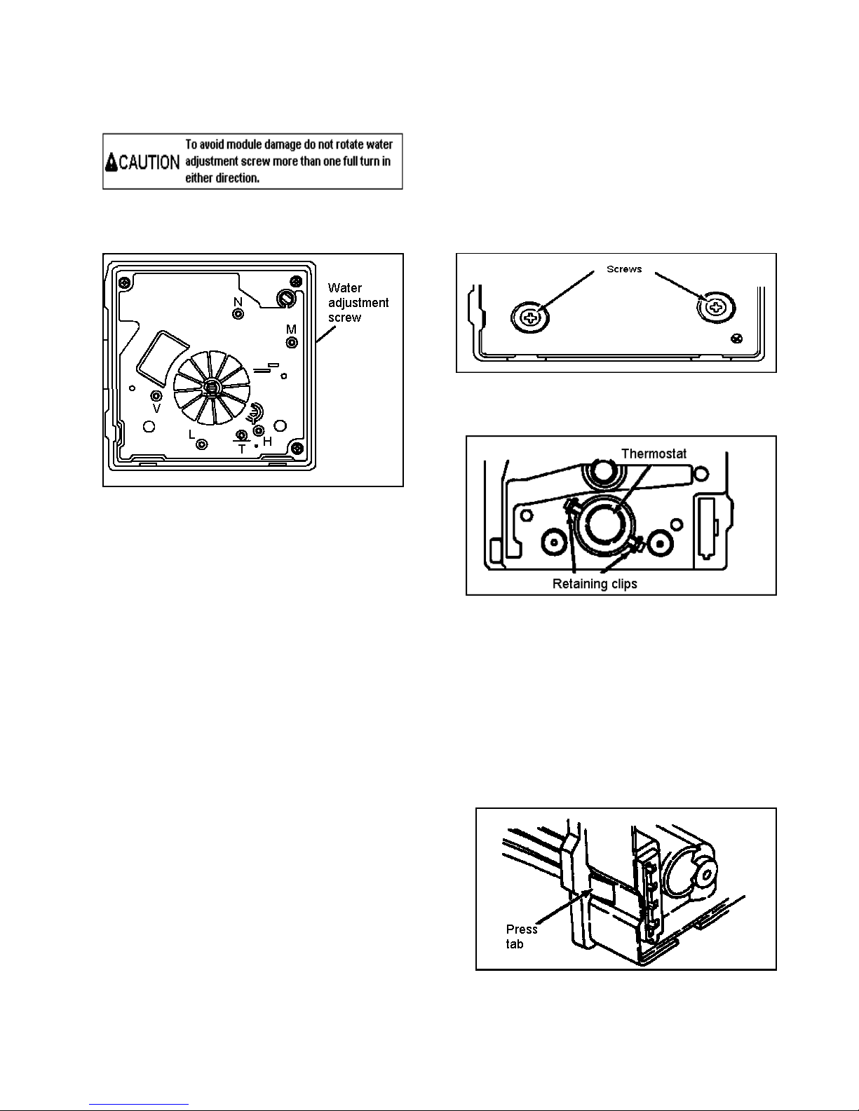
Turning water level adjustment screw will move
contact in relationship with contact ring segment.
This causes contact to vary time water valve is
energized. Contact ring is tapered at end of fill time.
• Turning screw clockwise decreases fill time.
• Turning screw counterclockwise increases fill
time.
• ½ turn equals 20 cc or 1.2 seconds.
• Full turn equals 40 cc or 2.4 seconds.
25
Page 26
Ice Maker
If water valve adjustment screw fall out, put screw in
hole and align as shown below.
When small hole is centered in large hole, water fill
adjustment is 7.5 seconds (normal fill time).
Water Problems
Poor water quality can cause ice maker to fail or
produce unacceptable cubes. Mineral content or sand
can restrict screen in water fill valve or particle of
sand can keep valve from seating properly.
If water valve does not close, the following could
occur
• no ice production
• small or hollow ice cubes
• flooding of ice container
Install water filter to eliminate bad taste, odor, and
visible contaminates.
Mineral contact can cause lime build up in mold,
Wicking of water over mold and poor cube release
can occur. Silicone is applied at upper edges around
fill cup and stripper.
Temperature Problems
Freezer temperatures above normal 0° ± 2° F (-18°±
1°C) will slow down ice production. Increase ice
production by setting freezer to colder setting.
Thermostat cycling temperature (1 revolution ice
maker) is 17° ± 3° F (-8° ± 1°C). Ice will freeze
when these temperatures are achieved. Cycling time
will be slower if freezer temperature is not cold
enough to achieve mode temperatures easily.
Thermostat, mold heater, and wiring harness are
replaceable. Any other failure, including motor,
requires replacement of module assembly.
Replacement mold assembly comes with new mold
heater installed.
Thermostat
1. Remove control box from mold be removing
screws.
2. Pull front of black housing free of mold.
Thermostat is on mold side.
3. Grasp 1 thermostat clip and pull out.
4. Press in new thermostat. Verify pins are
properly indexed. Electrical assembly does not
need to be removed.
If replacing module, transfer clips to new mold
support. Use new thermal bonding material.
Wiring Harness
Remove wiri ng har ness b y pressi ng ret aining t ab
and pulling forward.
26
Page 27
Ice Maker
Water Valve
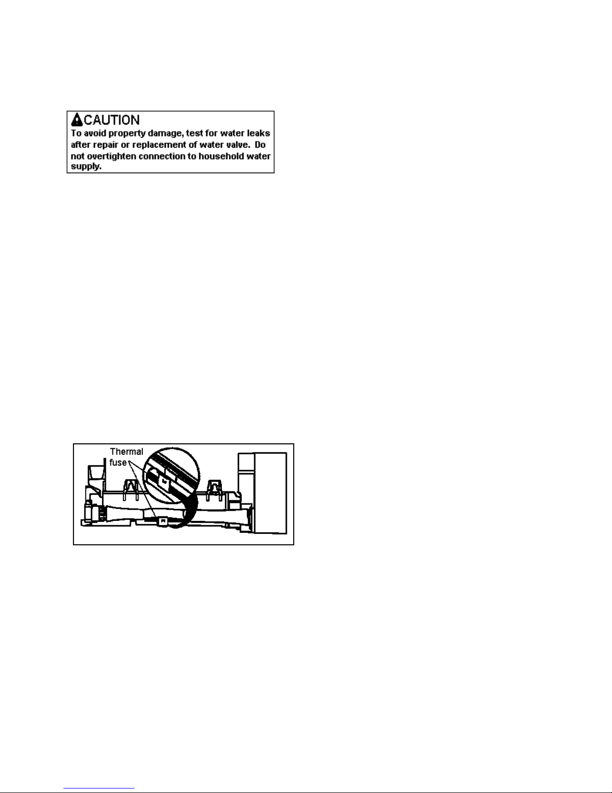
Water valve has 1 solenoid. Valve has 80 mesh
screen water strainer. When tan encapsulated
solenoid is energized, the amount of water entering
ice maker mold is directly proportional to length of
time water valve switch is held closed by timing cam.
Inside valve is a flow washer which acts as a water
pressure regulator. Proper ice maker fill is 140cc ±
10cc at 7.5 seconds of water fill at an inlet pressure
ranging from 20 to 120 PSI (1.4 to 8.2 bar).
Wire Harness
A non-resettable thermal fuse micro device 170° F
(78°C) is spliced into red wire of ice maker wiring
harness. Excessive heat can cause no ice production.
Replacing wiring harness will only temporarily solve
problem. Replace ice maker thermostats.
27
Page 28
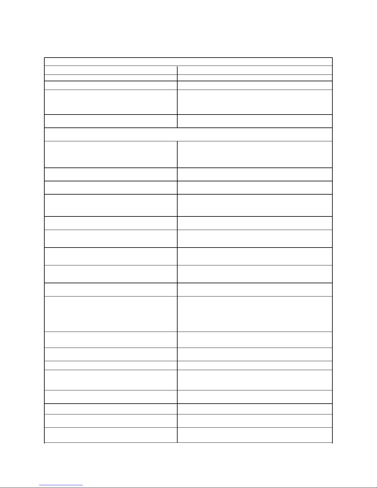
ICE MAKER TROUBLESHOOTING CHART
No or Low Ice Production
Problem Action
Warm freezer Adjust freezer control or repair refrigerator
Broken locking tab on vertical cam Replace Ice Maker
Shorted and burned module shut-off Replace Ice Maker
switch and contacts
Stalled or stripped motor Replace Ice Maker
2:30 Ejector Position
Contaminated module. Replace Ice Maker
Motor won’t run when “T” and “H” test
points are shorted.
Open or missing thermostat Replace or install thermostat Apply alumilastic
No power to ice maker (harness) Determine discontinuity by tracing power
Jammed cubes Un-jam cubes
Notice size and density of cubes Check fill tube cup assembly
Frozen fill tube Replace water valve
Kinked water line Un-kink line and check line for weak sections
Obstructed water line to ice maker or Clear water line
refrigerator.
Clogged water valve Replace water valve
No power to water valve Determine discontinuity by tracing power
Low water pressure Short “T” and “H” test points for 10 seconds.
Remove jumpers. Catch water in glass.
Increase water pressure to 20-120 (1.4-8.2 bar)
140cc’s.
Open heater circuit Replace Ice Maker
Closed thermostat Replace Ice Maker
Damaged heater tulips on module Replace Ice Maker
Short heater pins that do not Replace Ice Maker
contact module
Raised shut-off arm Lower shut-off arm to begin cycle
Water or ice in actuator/housing hole Replace Ice Maker
Small or burred housing hole Replace Ice Maker
Large or burred actuator O.D. Replace Ice Maker
28
Page 29
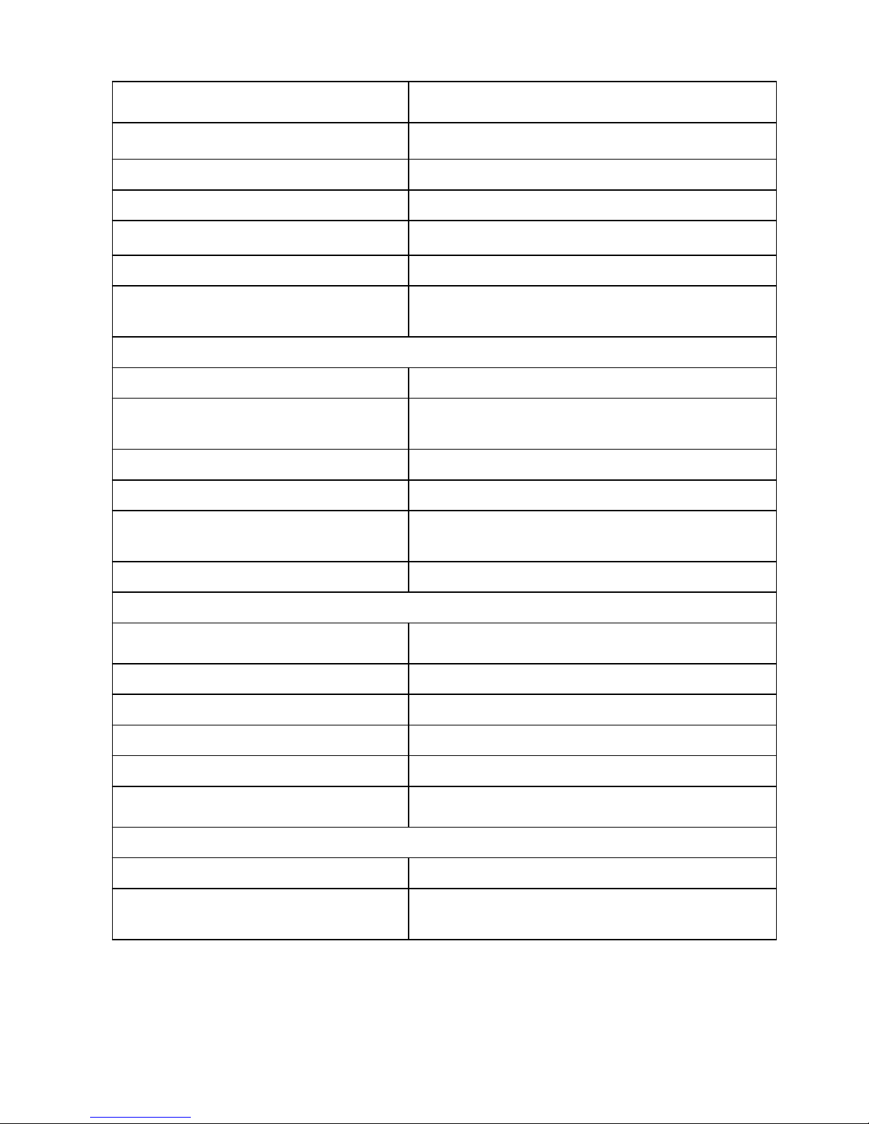
Damaged module housing Replace Ice Maker
Deformed shut-off arm Replace shut-off arm
Little or no alumilastic on thermostat Apply alumilastic to thermostat
Housing to mold screws not seated Tighten 2 screws (20-26 in.lb) (22.8-29.6 cm.kg)
Heater not staked in mold Replace Ice Maker
Incorrect heater temperature Replace Ice Maker
Broken shut-off lever or Replace Ice Maker
mislocated shut-off switch
3:00 Ejector Position
Contaminated Replace Ice Maker
Jammed cubes Un-jam cubes
Notice size and density of cubes
Refrigerator or ice maker not level level refrigerator or ice maker
No power to ice maker Determine discontinuity be tracing power
Excessive water fill volume Adjust module screw, lower water pressure or replace
water valve.
Cubes falling back into mold during ejection Replace fill cup. Check fill tube assembly.
4:00 Ejection Position
Contamination Replace Ice Maker
Thermostat out of calibration Replace Ice Maker
Open heater circuit, motor should oscillate Replace Ice Maker
Little or no alumilastic on thermostat apply alumilastic to thermostat
Heater not staked in mold Replace Ice Maker
Broken locking tabs on vertical cam Replace Ice Maker
6:00 Ejection Position
Contamination Replace Ice Maker
Insufficient water to ice maker, Refer to “Hollow Ice Cubes”
small or hollow cubes
29
Page 30
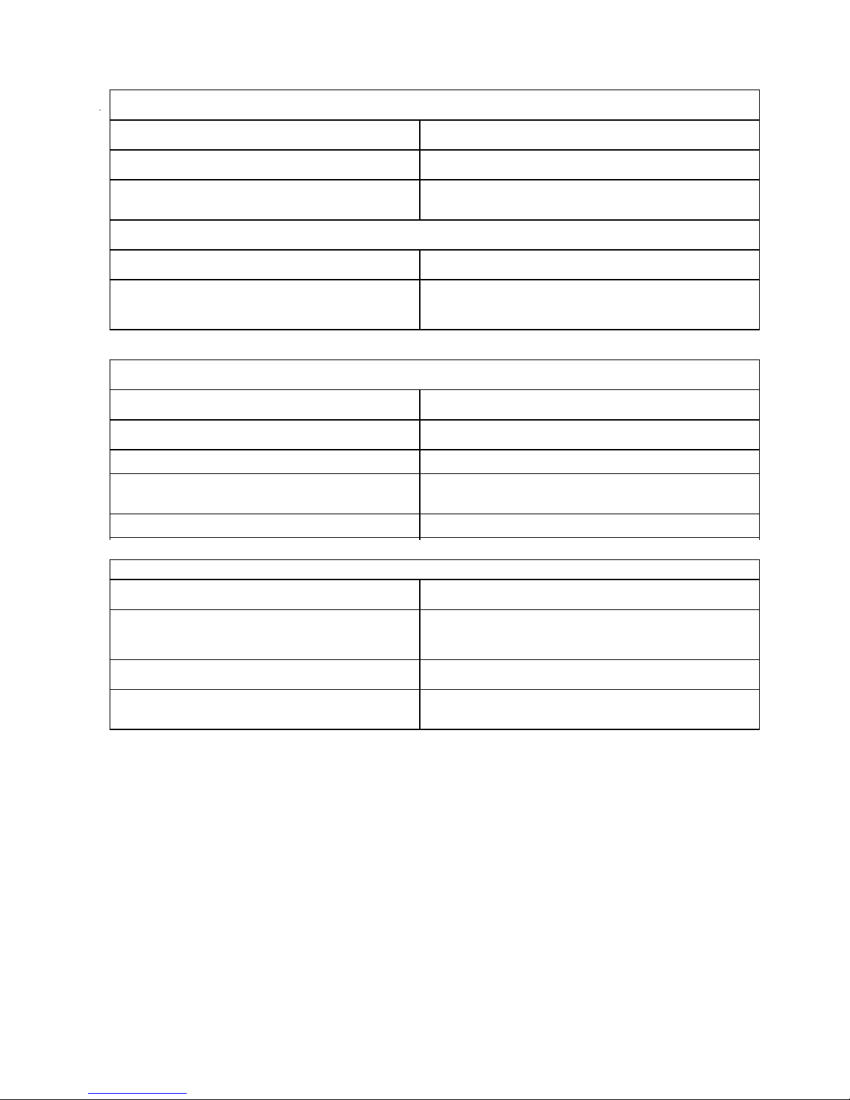
7:30 Ejection Position
Contamination—Motor will not oscillate Replace Ice Maker
Shut-off arm stuck in ice or obstructed Unjam
Cubes not formed properly Check fill cup and fill a ssembly
9:00 Ejection Position
Contaminated Replace Ice Maker
Cube frozen to fill cup or mold Unjam
Replace fill cup and replace Ice Maker
Excessive Ice Production
Problem Action
Shut-off arm not in actuator Replace shut-off arm in actuator
Deformed shut-off arm Replace shut-off arm
Broken shut-off lever or lever bypassing Replace Ice Maker
vertical cam
Broken module actuator Replace Ice Maker
Hollow Ice Cubes
Problem Action
Low water fill volume Adjust module screw, clear water path, or
replace water valve
Improper freezer air flow Direct air flow away from thermostat
Thermostat out of calibration Replace Ice Maker
30
Page 31
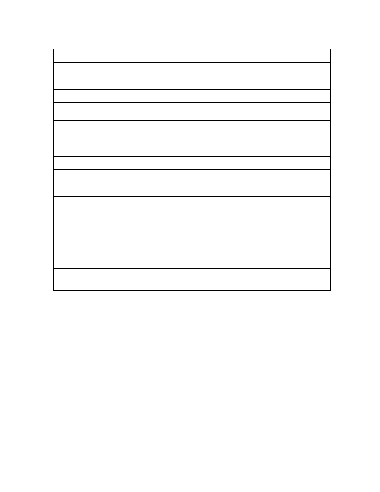
Flooding or Ice in Bucket or Freezer
Problem Action
Thermostat out of calibration Replace Ice Maker
Jammed cube stalled in water-fill cycle Remove cube. Determine reason for stall
Leaky water valve Replace water valve
Excessive water fill volume Replace water valve
Motor stalled in water-fill cycle Replace Ice Maker
(12:00 ejection position)
Contaminated module Replace Ice Maker
Refrigerator or ice maker not level Level refrigerator or ice maker
Excessive water pressure Decrease water pressure (20-120 psi (1.4-8.2 bar)
Shorted and burned module shut-off Replace Ice Maker
switch and contacts.
Broken locking tab on vertical cam Replace Ice Maker
(stalled in water fill)
Fill tube not properly positioned in fill cup Reposition fill tube
Fill cup water opening blocked Replace fill cup
Cubes fall over back of ice maker, Replace fill cup
melting in freezer.
31
Page 32
32
Page 33

Filename: VCSB48132.doc
Directory: D:\VBCODE\IPLUTILS\PDFGenerator\InputData\F90561 VCSB 481-482
Template: C:\Documents and Settings\tomw.EYECOM\Application
Data\Microsoft\Templates\Normal.dot
Title:
Subject:
Author: Viking Range
Keywords:
Comments:
Creation Date: 10/25/2001 8:30 AM
Change Number: 2
Last Saved On: 3/28/2003 4:01 PM
Last Saved By: Ken Sievert
Total Editing Time: 1 Minute
Last Printed On: 3/28/2003 6:15 PM
As of Last Complete Printing
Number of Pages: 1
Number of Words: 0 (approx.)
Number of Characters: 1 (approx.)
 Loading...