

Page 1
VCSB360 / 420 / 480
VIKING RANGE CORPORATION, P.O. DRAWER 956, GREENWOOD,MS 38930 USA
Page 2

TABLE OF CONTENTS
TOOLS NEEDED FOR REPAIRS..................................................................................... 3
COMPONENT LOCATION
Theory of Operation........................................................................................................ 4-12
COMPONENTS ACCESS AND REPAIR
Components in the Refrigerator Section........................................................................ 13
1. Electronic Control Board................................................................ 13
2. Light Switch........................................................................................ 14
3. Motorized Air Door........................................................................... 15
4. Temperature Sensor (Thermistor)................................................... 15
5. Meat Locker Control......................................................................... 16
Components in the Freezer Compartment
1. Removing Freezer Thermostat......................................................... 17
2. Removing Light Switch..................................................................... 18
3. Removing the Evaporator Fan Motor............................................. 19
4. Removing the Bi-metal...................................................................... 20
5. Removing the Defrost Heater............................................................ 21
6. Installing a New Defrost Heater....................................................... 22
Components on Top of the Unit...................................................................................... 23
1. The Power On / Off Switch............................................................... 24
2. Removing the Defrost Timer............................................................. 25
3. Removing the Run Capacitor........................................................... 25
4. The Condenser Fan Motor................................................................ 26
5. The Water Valve................................................................................ 27
Door Assemblies
Replacing the Door Gaskets..................................................................... 28
TROUBLE SHOOTING AND DIAGNOSIS................................................................................ 29--40
R134a REFRIGERANT SERVICE INFORMATION............................................................ 41
MODULAR ICE MAKER SERVICE SHEET............................................................................ 42
WIRING DIAGRAMS AND LINE CIRCUITS........................................................................... 43-- 60
APPENDIX:
Refrigerator Installation Cutout ................................................................................... 61
Adjust Door Swing........................................................................................................... 62
Level Refrigerator............................................................................................................ 62
Installing Custom Side Panels........................................................................................ 63
2
Page 3

VIKING RANGE CORP.
BUILT-IN REFRIGERATOR / FREEZER
Tools Needed For Repair
1. Channel locks or 5/8" open end wrench
2. Medium size Phillips screwdriver
3. Medium & small straight blade screwdriver
4. Needle nose pliers
5. Socket set with medium & long extensions, socket sizes ½" to 1/4"
6. Set of nut drivers ½" to 1/4"
7. #15 Torx driver
8. Six foot step ladder
9. Sealed system equipment for R134a
3
Page 4
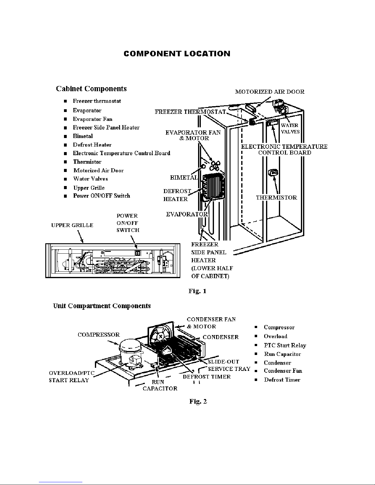
4
4
Page 5
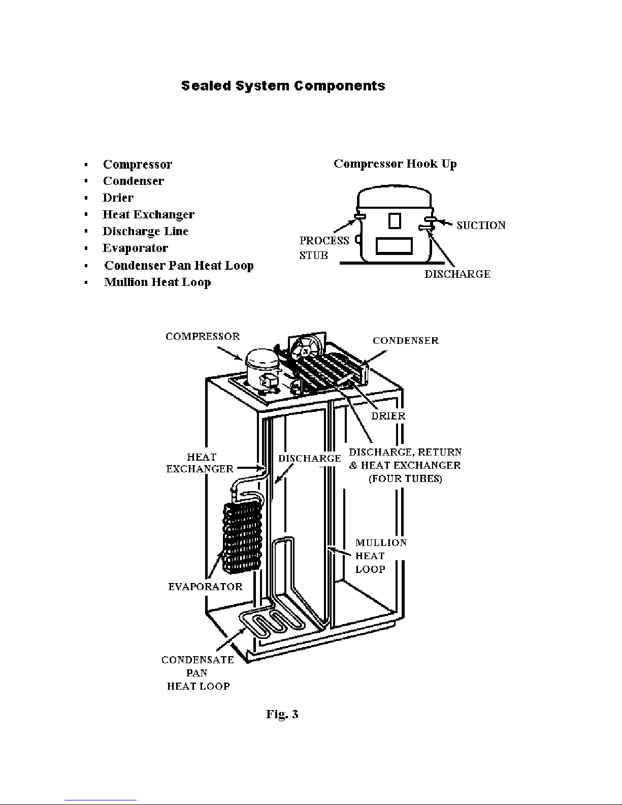
5
5
Page 6
6
Page 7
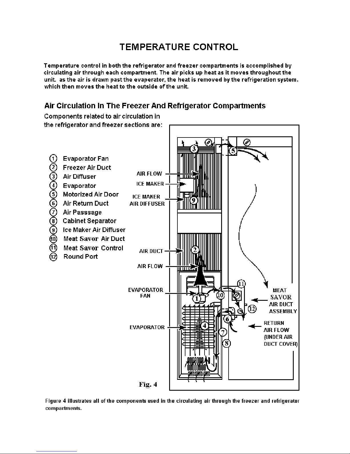
The Freezer Compartment
The evaporator fan (1) draws air over the evaporator coils (4) located in the lower portion of the freezer
compartment. As the air passes over the evaporator, heat is extracted and the cold air travels up the back
of the freezer compartment through an air duct (2) to the top of the unit.
An air diffuser (3) at the top of the freezer compartment allows the cold air to circulate into the freezer
area and drop to the bottom of the compartment where it is drawn over the evaporator again.
Air traveling up the freezer air duct is also directed out the small diffuser (9) just below the ice maker.
The air travels along the bottom of the ice maker to the front of the freezer and down toward the bottom
of the compartment and then up through the evaporator coils (4).
The Refrigerator Compartment
An air duct regulated by a motorized air door (5) located at the top of the freezer section allows cold air to
pass through the separator wall (8) into the refrigerator section. Air then circulates throughout the
refrigerator section, generally flowing from top to bottom. As it reaches the bottom of the refrigerator
section it is drawn through a return air duct (6) in the separator (8) wall located just below the meat savor
drawer. This return air is drawn to the bottom of the freezer compartment through a passage between the
side of the evaporator (7) and the separator wall (8) and then up past the evaporator coils (4).
Cold air from the freezer section also enters the meat savor drawer through a small air duct (10) in the
separator wall (8). Air travels through the meat savor control (11). If the baffle in the meat savor control
is open, the air travels out the round port (12) into the back of the meat savor drawer. The air exits the
meat savor drawer and returns to the freezer through the return duct (6) The air then travels down
between the side of the evaporator (7) and the separator wall (8) and then up through the evaporator coils
(4).
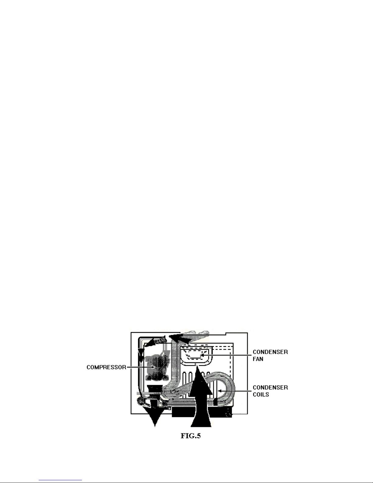
Air Circulation In The Component Compartment
A second air circulation system in the component compartment at the top of the unit dissipates the heat
picked up by the refrigeration system ( Fig. 5). The condenser fan, located at the back of the
compartment draws room air across the condenser, absorbing the heat in the refrigerant. This warmed air
is then exhausted through a grille located at the left of the compartment behind the decorative grille
assembly.
7
Page 8
Motorized Air Operation
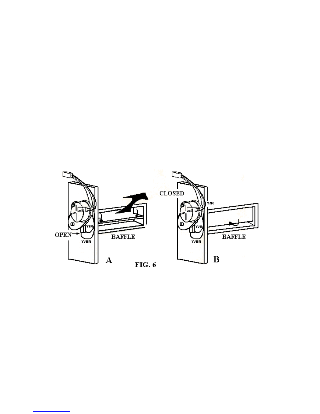
A motorized air door regulates the air flow coming from the freezer. The operation of the motorized air
door is determined by the following components:
• The temperature sensor (thermistor) located on the back wall of the refrigerator cover.
• The electronic control board located inside the refrigerator section control cover.
When the temperature sensor calls for cooling in the refrigerator section, the electronic control energizes
the air door motor and opens the baffle (Fig 6-A). from the “closed” position, the baffle rotates clockwise
270°. During this rotation it opens, closes and then parks in the “open” position. The OPEN MICROSWITCH shuts the door motor off when the baffle is fully open.
When the temperature sensor is satisfied, the electronic control again energizes the air door motor and
closes the baffle (Fig 6-B). from the “open” position, the door rotates clockwise 90° and parks in the
“closed” position. The CLOSED MICRO SWITCH shuts off the door motor when the baffle is fully
closed.
Air Circulation in the Meat Savor Drawer
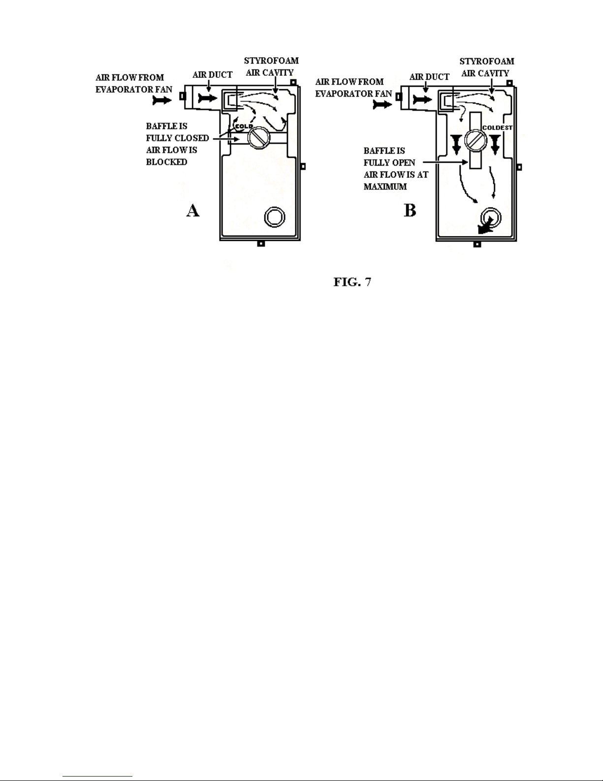
The Meat Savor drawer in the refrigerator compartment is provided with a separate controlled flow of
cold air from the freezer compartment. Air enters the Meat Savor drawer through an air passage through
the center divider wall into the upper part of the Meat Savor drawer control. If the control knob is rotated
fully counterclockwise the control knob arrow is pointing to “COLD” (Fig 7A). In this position the cold
air is blocked by the baffle and will not enter the Meat Savor drawer.
As the control knob is turned clockwise (toward the “COLDEST” setting), cold air will be able to pass
around the baffle into the lower part of the Meat Savor control it can flow through the round port into the
Meat Savor drawer. Air then leaves the drawer and joins the normal air circulation in the refrigerator
compartment and return to the freezer compartment through the return air ducts in the center divider wall.
8
Page 9
Control and Operation
The temperature controls in the built-in refrigerator/freezer are designed to regulate temperature more
accurately and operate the product more efficiently than freestanding side-by-side refrigerator/freezers.
Freezer Thermostat Control
The freezer thermostat controls the temperature of the freezer compartment be sensing cold air coming
from the cold air duct on the back wall of the freezer liner. The thermostat’s sensing tube is located in the
upper right side and upper back of the freezer compartment and is covered by plastic wiring covers
When the thermostat calls for cooling, the following components are energized:
• Compressor
• Condenser
• Defrost Timer Motor
• Freezer Side Panel Heater
In addition, the thermostat sends a signal to the electronic control board indicating that the compressor is
running. The electronic control board then energizes the evaporator fan motor. Although the evaporator
fan motor is energized independently through the electronic control board, it always runs when the
compressor is operating. This insures air circulation across the evaporator coils and through the freezer
compartment during the compressor “on” cycle.
Refrigerator Electronic Temperature Control
The refrigerator electronic temperature control system consists of a thermistor and an electronic control
board. The flexibility of the electronic control enables the refrigerator to operate with greater efficiency
by activating the motorized air door and the evaporator fan motor independently of the compressor
circuit.
9
Page 10

• The electronic control board continuously sends a flow of voltage, or signal current, through the thermistor.
The thermistor is sensitive to temperature fluctuations and changes resistance accordingly. When the
temperature rises in the refrigerator compartment:
• The thermistor resistance decreases, altering the signal going to the electronic control board.
• The electronic control board, sensing the change in the signal current:
a) Energizes the motorized air door to open.
b) Energizes the evaporator fan motor (if it is not already running during a compressor “on”
cycle).
When the refrigerator compartment temperature decreases:
• The thermistor resistance increases, altering the signal current to the electronic control board.
• The electronic control board sensing the change in the signal current:
a) Closes the air door.
b) Cycles the evaporator fan motor off (if the compressor is not running).
The electronic control board is operated by a variable resistor, or potentiometer, which sets the desired refrigerator
compartment temperature. Adjusting the potentiometer changes the sensitivity of the electronic control board to the
signal current from the thermistor. Varying the sensitivity raises or lowers the regulated temperature.
The refrigerator thermistor and the electronic control board directly affect the operation of the evaporator fan motor
and the motorized air door. Evaporator fan motor and motorized air door cycling may occur one or more times
before the freezer calls for a cooling cycle.
Control Interaction
The following information explains how the freezer thermostat and the refrigerator electronic temperature control
system interact.
When the freezer thermostat closes (calling for cooling):
• The cycle is initiated.
• A voltage signal is sent to the electronic control board.
• The electronic control board energizes the evaporator fan motor.
• If the thermistor is satisfied, the motorized air door remains closed.
• If the thermistor is calling for cooling, the motorized air door opens.
When the freezer thermostat opens (is satisfied):
• The cooling cycle is terminated.
• The voltage signal to the electronic control board is terminated.
• If the thermistor is satisfied, the motorized air door is closed and the evaporator fon motor is turned off.
• If the thermistor is calling for cooling, the motorized air door opens and the evaporator fan motor runs.
10
Page 11

Defrost System
As air circulates through the refrigerator/freezer, moisture from food and outside air that enters whenever
the doors are opened condenses and freezes onto the evaporator coils and fins to form a layer of frost.
Periodically the frost must be cleared from the coils so that the air flow is not blocked. An automatic
defrost function accomplishes this task with the use of a defrost timer, defrost heater and bimetal.
The defrost system is designed to initiate the defrost function following 10 hours of accumulated
compressor run time. The defrost timer motor runs during a cooling cycle when the compressor runs and
stops running when the compressor cycles off. The timer motor also runs during the defrost cycle when
the refrigeration system is shut down.
Once initiated, the defrost cycle lasts 21 minutes. The defrost heater is energized and melts off any frost
accumulation. When the evaporator area reaches approximately 50* F, the bimetal opens and turns off
the defrost heater. This usually occurs 10 to 15 minutes after the defrost cycle begins. The defrost timer
motor continues the defrost cycle for the full 21 minutes duration and then the cooling cycles resume.
During the defrost cycle the following occurs:
a) The evaporator fan motor does not run.
b) The motorized air door does not operate. The air door stays in its present position
The thermostat is bypassed and has no controlling function.
The compressor run signal current, from the thermostat to the electronic control board,
is interrupted. The electronic control board will not sense or regulate the temperature.
Voltage is interrupted from the thermostat to the electronic control board.
(either open or closed) until the defrost cycle is over.
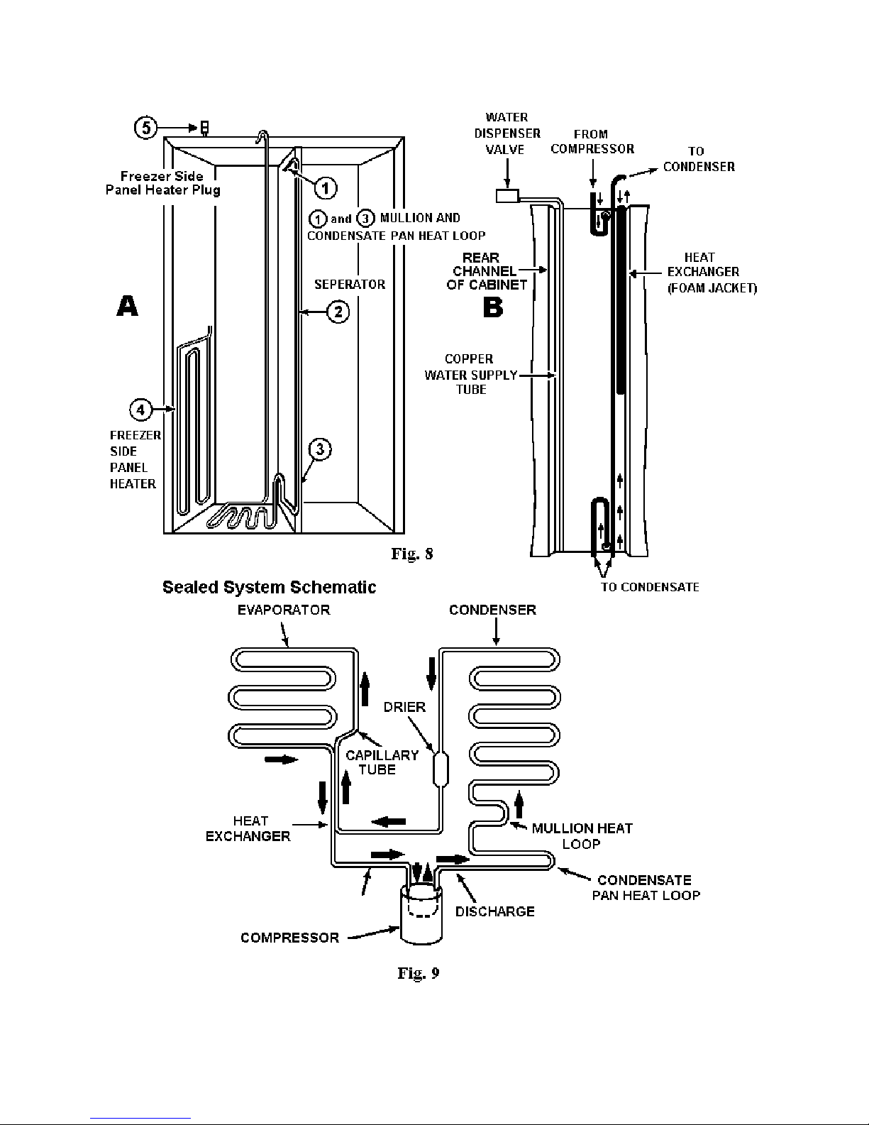
The Mullion and Condensate Pan Heat Loop
The mullion and condensate pan heat loop (Fig.8 A) enters the separator wall through a grommet in the
back of the cabinet (Fig.8 B) where it travels inside the separator wall to the front. It then bends 90* (1)
and travels along the entire length of the separator (2) to the bottom of the cabinet. Finally, the loop
bends 90* (3) and travels along the bottom of the separator and exits through a grommet at the back of the
cabinet.
The loop then makes a 180* trap and travels down underneath the cabinet and forms a coil over the
condensate pan. The loop then travels up the back of the cabinet to the condenser.
The Freezer Side Panel Heater
The freezer side panel heater element (4) is affixed to an adhesive sheet on the left inside wall of the outer
cabinet and is foamed in place during manufacture. The element covers the bottom half of the wall and is
energized whenever the freezer thermostat initiates a cooling cycle and the compressor runs. The plug (5)
for the freezer side heater is located near the top left corner of the cabinet.
11
Page 12
12
Page 13
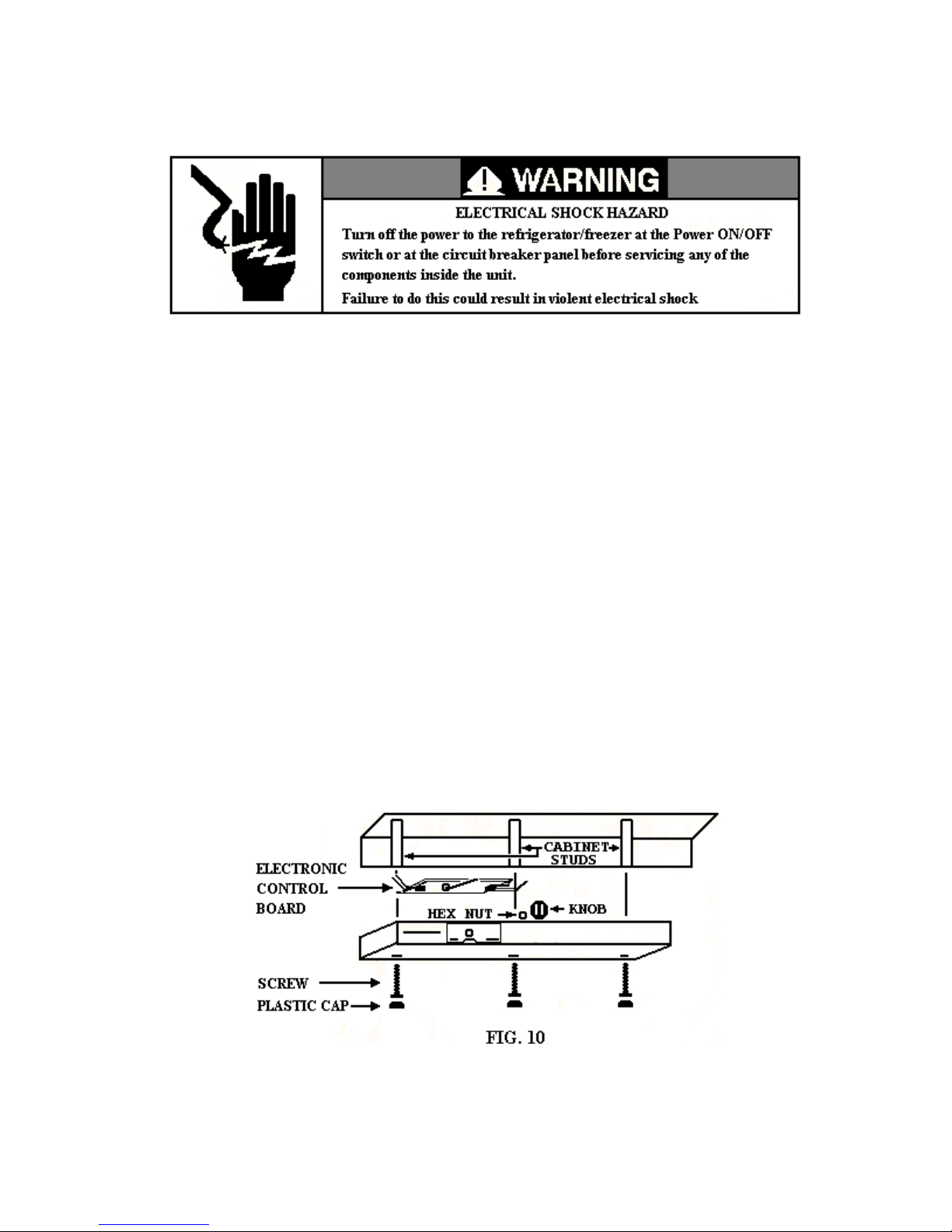
COMPONENT ACCESS
The following information provides specific information on accessing components of the built-in side-byside refrigerator/freezer. This section will be presented in four parts:
• Components in the refrigerator section
• Components in the freezer section
• Components in the top of the unit
• Door assemblies
COMPONENTS IN THE REFRIGERATION SECTION
The components that are accessible in the refrigerator compartment are:
• The Electronic Control Board
• Light Switch
• Motorized Air Door
• Temperature Sensor (Thermistor)
• Meat Savor Control
Servicing the Electronic Control Board
The electronic control board is located inside the control box at the top of the refrigerator section.
13
Page 14
1. Pull the knob from the control shaft.
2. Remove the one-half inch hex nut securing the control shaft to the control box cover.
3. Pry the three plastic caps from the control box cover.
4. Remove the three Phillips head screws securing the control box cover to the top of the cabinet.
5. Rotate the control box cover down to expose the contents of the control box.
6. Press down on the ends of the locking arm on the wiring connectors and unplug the two
connectors from the electronic control board.
7. Slide the old control board from the slots in the control box cover.
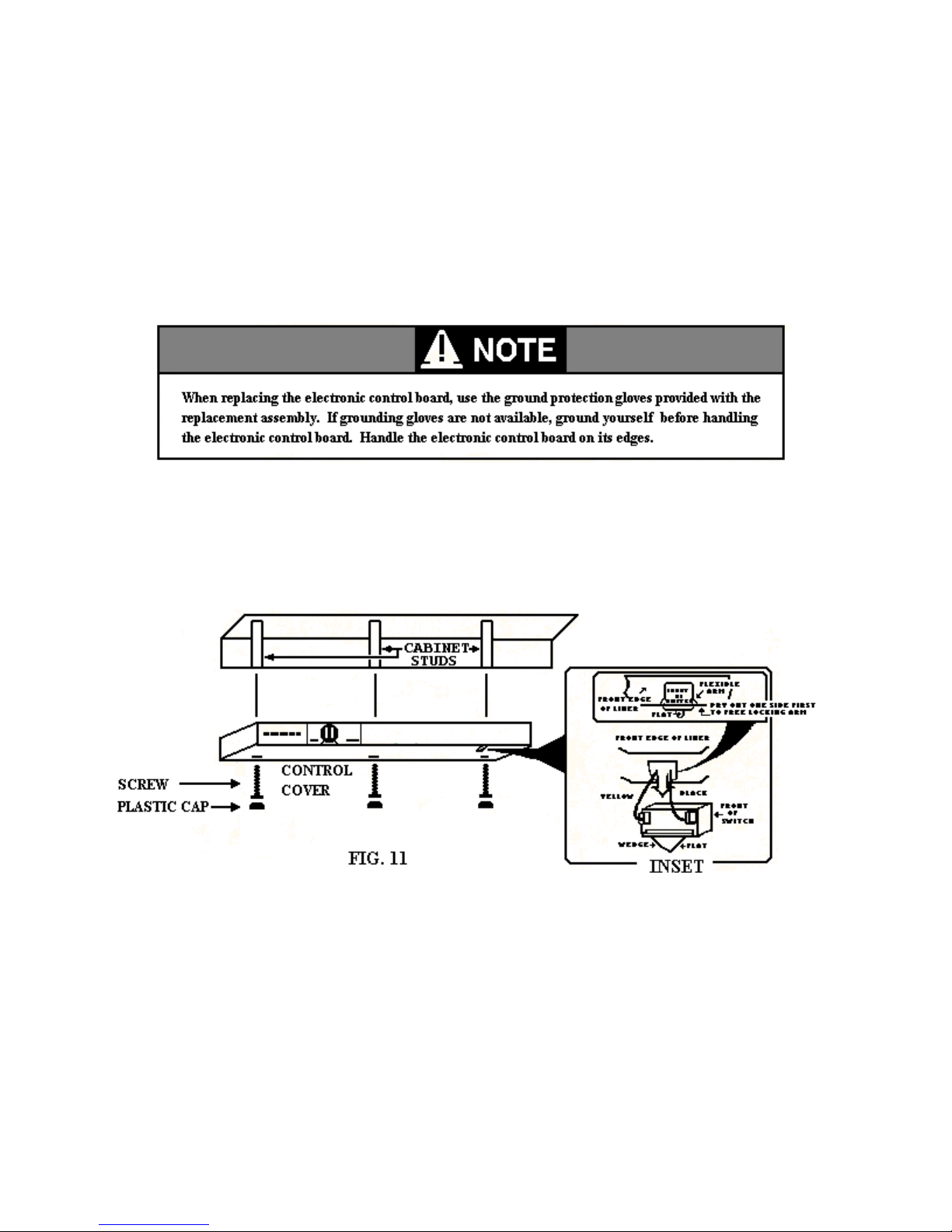
Servicing the Light Switch
The light switch that activates the lights inside the refrigerator section is located on the underside of the
control box.
. Follow the procedure described earlier to remove the control board cover from its position at the
1
top of the refrigerator section.
2. th connectors from the light switch.
Unplug e yellow and black wire
3. Press on the flexible arm of the light and pry the opposite side out
cover.
of the hole in the control box
14
Page 15
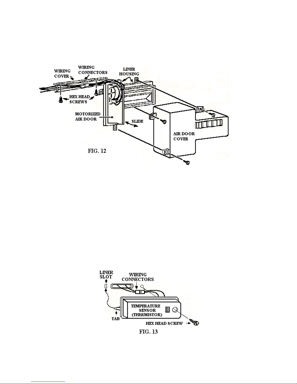
Servicing the Motorized Air Door
The motorized air door assembly is located in the upper rear left corner of the refrigerator section.
1. Remove the three hex head screws securing the air door cover to the cabinet liner and set the
cover aside.
2. Remove the two hex head screws securing the wiring cover to the top of the refrigerator section
liner and remove the wire cover.
3. Disconnect the motorized air door wiring connector from the wiring harness.
4. Slide the motorized air door assembly out of the slot in the liner housing.
Servicing the Thermistor
The refrigerator section temperature sensor is located on the left side of the back wall of the cabinet
approximately one third of the way from the top.
15
Page 16
1. Remove the hex head screw securing the temperature sensor assembly to the back wall of the
cabinet liner.
2. Lift the right side of the assembly slightly and unhook the tab on the left end from the slot in the
cabinet liner.
3. Unhook the locking arm on the temperature sensor connector from the tab on the wiring harness
connector and unplug the connectors.
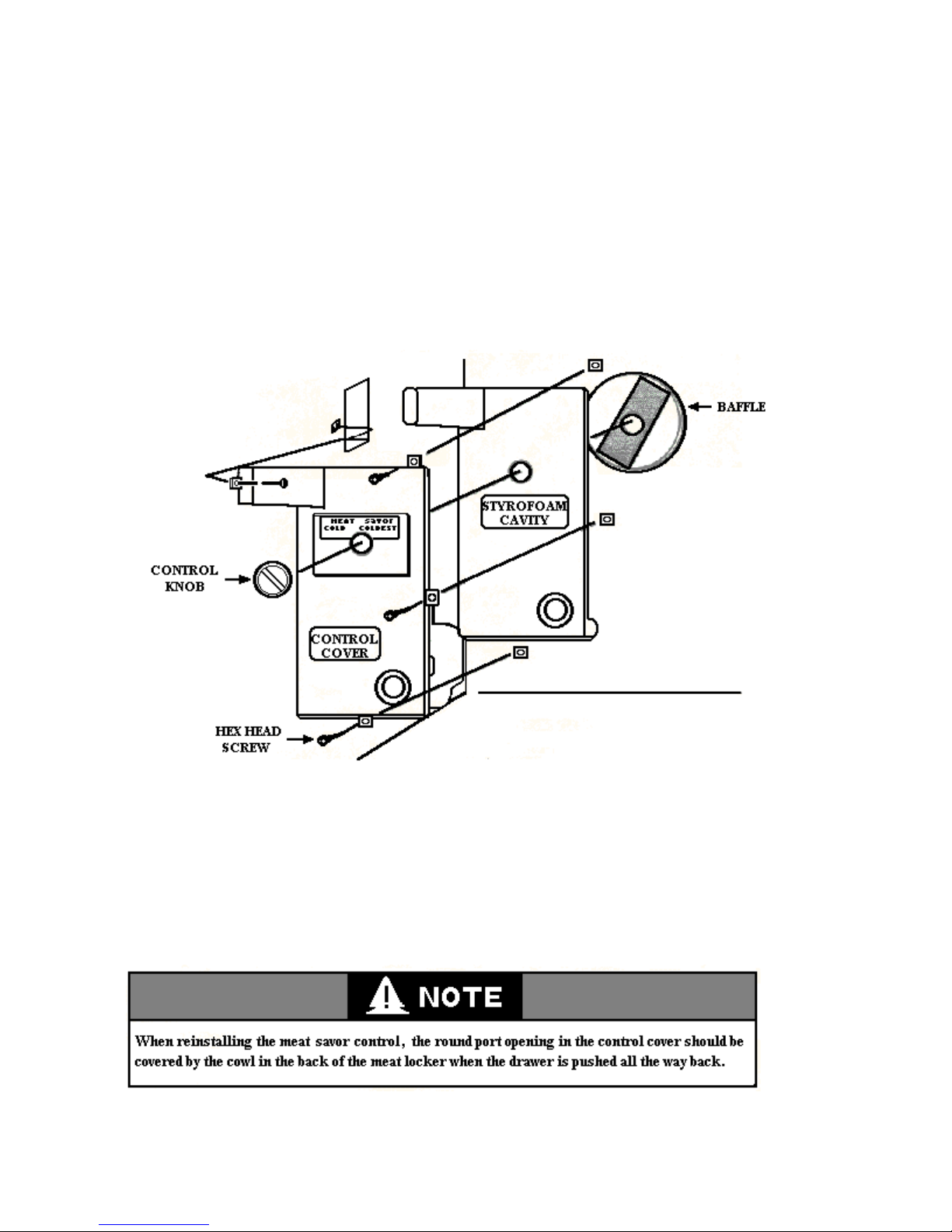
Servicing the Meat Savor Control
The control for the meat savor air baffle is located on the left side of the rear wall of the refrigerator
section and will require that the meat savor shelf and drawer be removed for access.
1. Remove the four hex head screws securing the meat savor control to the cabinet liner.
2. Remove the control knob, control cover, styrofoam cavity and baffle.
16
Page 17
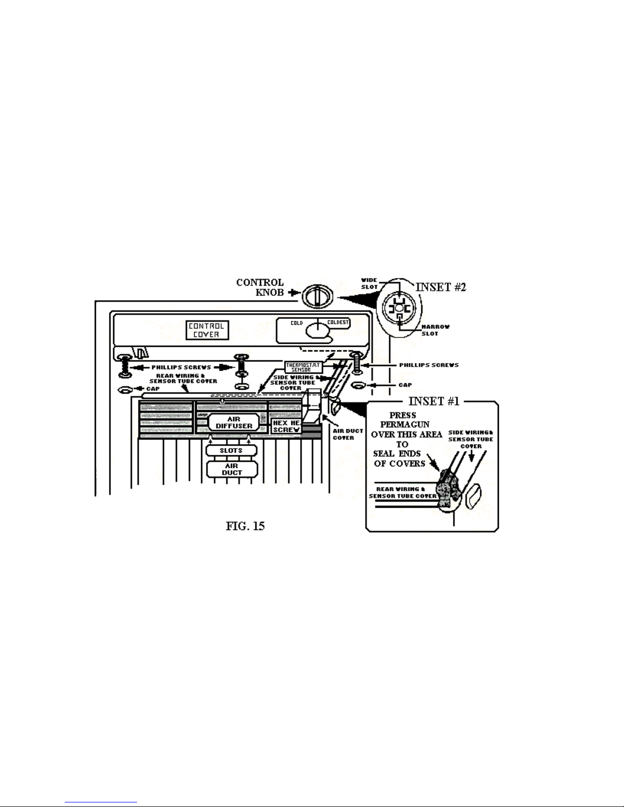
COMPONENTS IN THE FREEZER COMPARTMENT
The components that are accessible in the freezer compartment are:
• The freezer thermostat
• Light switch
• Evaporator fan motor
• Bimetal
• Defrost heater
Servicing the Freezer Thermostat and Light Switch
The freezer thermostat and the light switch are located in the control box at the top of the freezer
compartment.
1. Remove the hex head screw securing the air duct at the upper right rear corner of the freezer and
remove the cover.
2. Remove the two hex head screws securing the side wiring harness cover to the upper right side of
the freezer and remove the cover.
3. Slide the air diffuser at the top of the freezer up and remove the air diffuser from the freezer
section.
4. Carefully remove the permagum from the upper right rear cover of the freezer. This material will
have to be reinstalled later. Keep it clean and safe.
5. Remove the three hex head screws securing the rear wiring harness cover to the top of the freezer.
17
Page 18
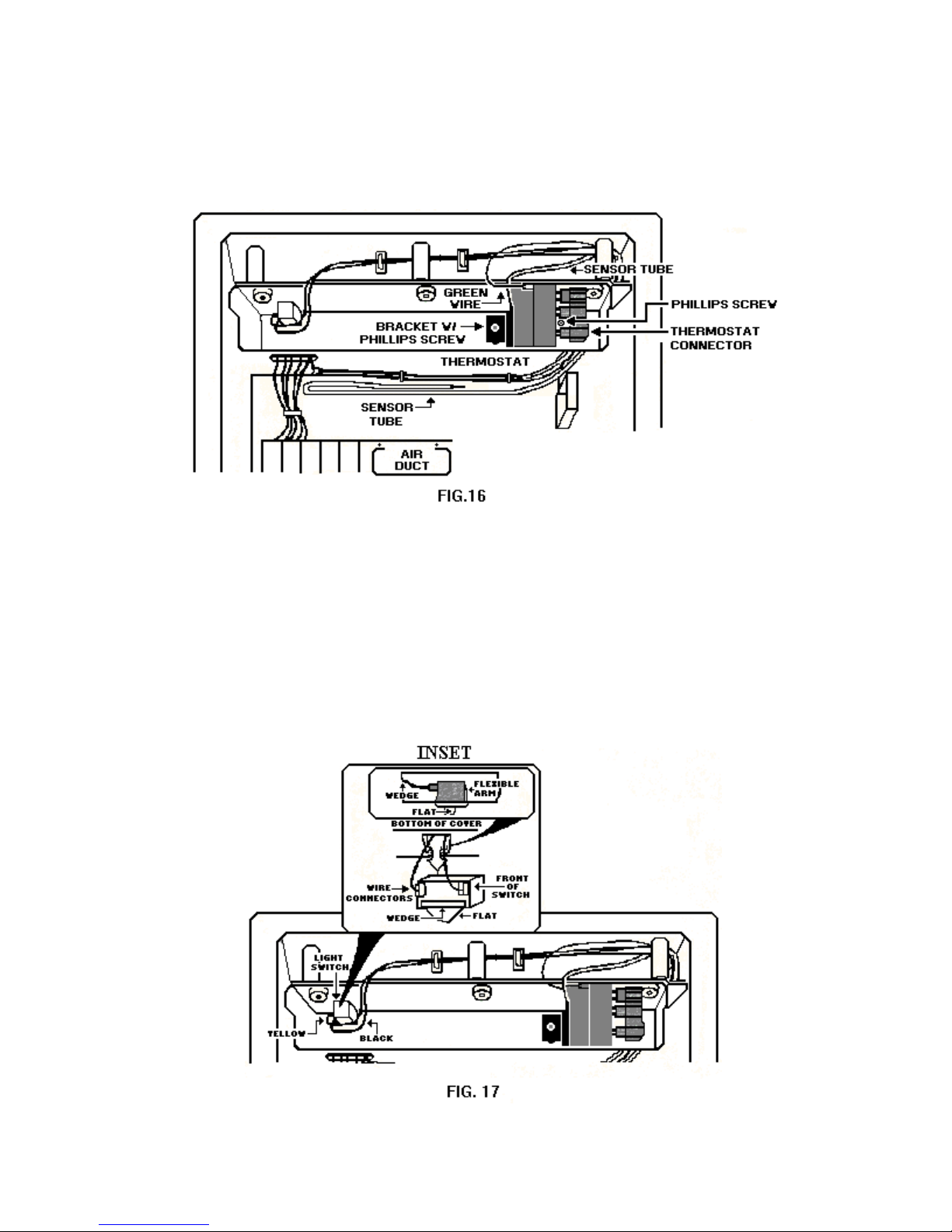
6. Remove the three plastic caps that cover the Phillips securing the control box cover to the top of
the freezer and remove the screws.
7. Rotate the control box cover so it can be worked on. Once the control box cover is in this
position the light switch and thermostat can be serviced.
1. Pull the green ground wire connector from the thermostat ground terminal.
2. Pull the wire connector from the three thermostat terminals.
3. Remove the two Phillips screws securing the thermostat bracket to the control box cover.
4. Carefully remove the thermostat and the freezer sensor tube from the freezer compartment.
Removing the Light Switch
18
Page 19
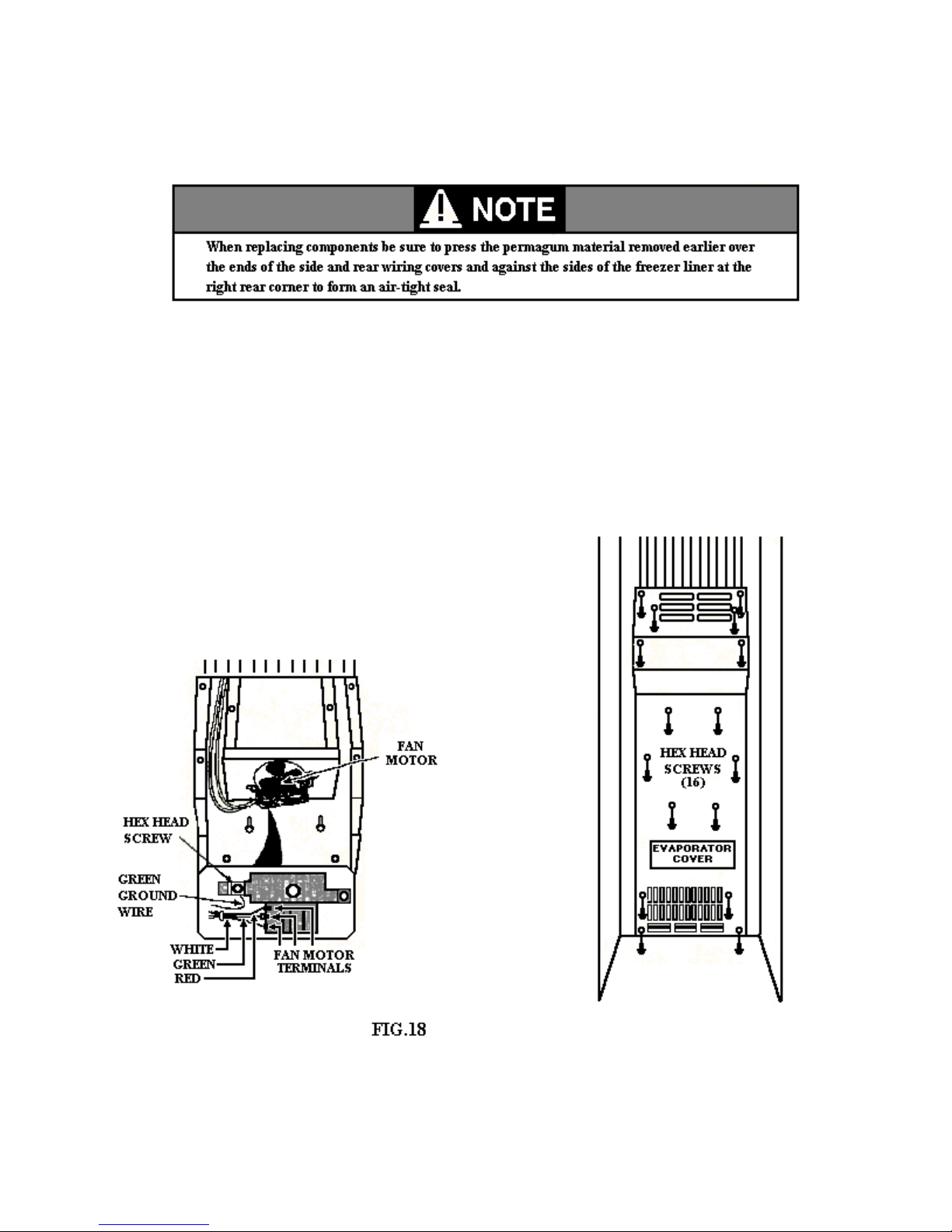
1. Unplug the yellow and black wire from the switch terminals.
2. Press in on the flexible arm of the switch and pry the opposite side of the switch out of the hole in
the corner cover.
Servicing Components Behind the Evaporator Cover
A number of serviceable components are located behind the evaporator cover located on the lower portion
of the back wall of the freezer section.
1. Remove the sixteen hex head screws securing the
evaporator cover to the back wall of the freezer liner.
2. Pull the top of the evaporator cover out between
shelf studs and remove it from the freezer.
Removing the Evaporator Fan Motor
The evaporator fan motor and blade assembly is mounted
on a bracket secured to back of the freezer liner.
19
Page 20
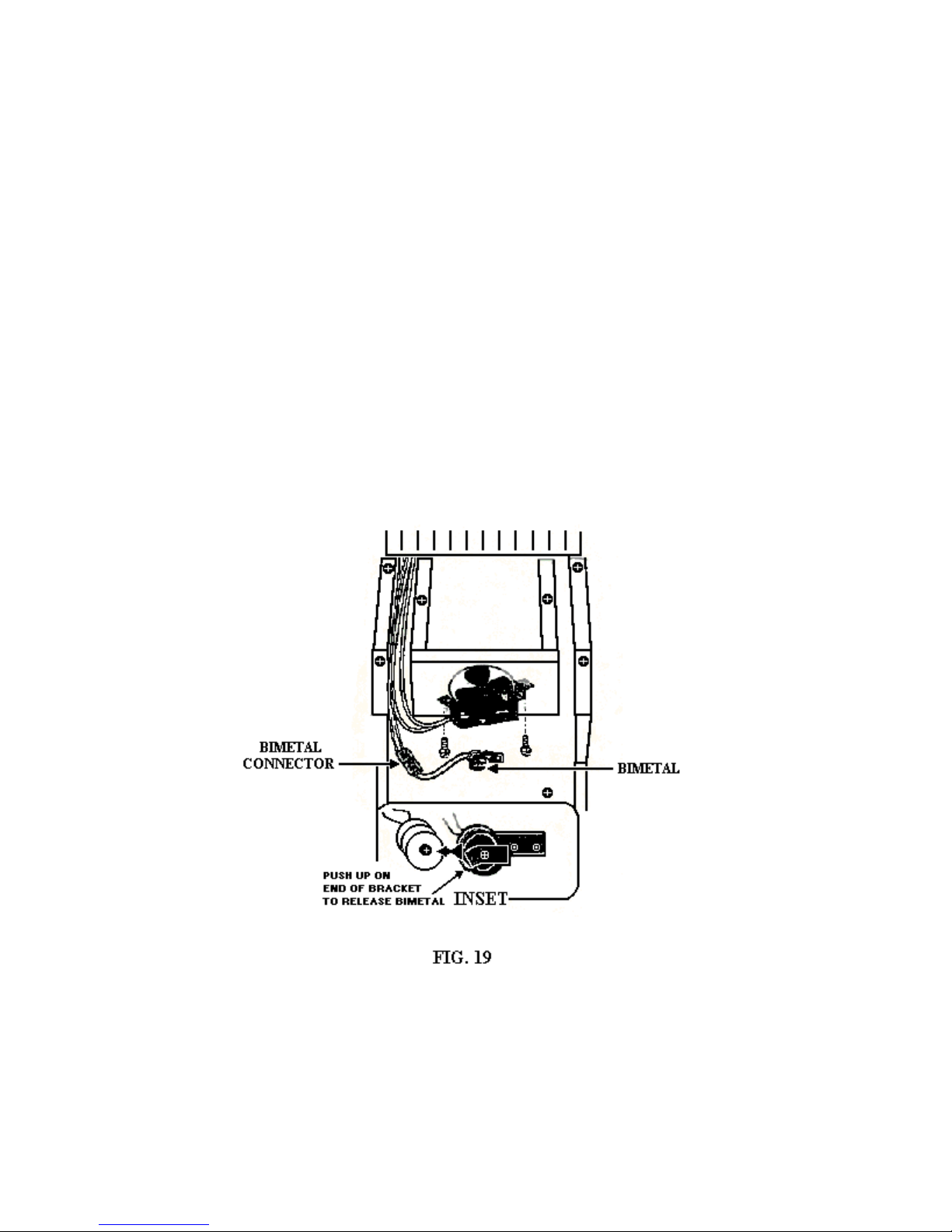
1. Remove the two hex head screws from the fan motor bracket.
2. Remove the three wires from the terminals on the fan motor.
3. Remove the two hex head screws securing the fan motor to the mounting bracket and remove the
bracket from the motor.
4. If the motor is to be replaced, remove the blades from the motor shaft.
Removing the Bimetal
The bimetal is located behind the evaporator cover.
1. Push up on the bimetal bracket just enough to release the locator pin on the bimetal and remove
the bimetal from the bracket.
2. Unplug the connector from the wiring harness connector.
20
Page 21
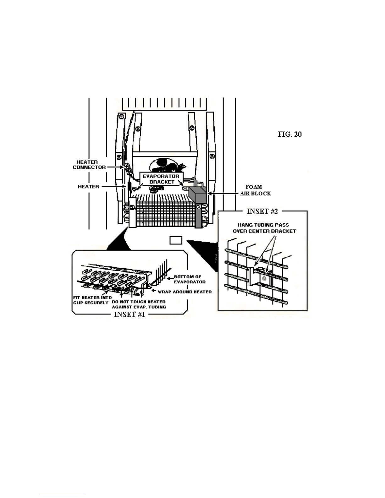
Removing the Defrost Heater
The defrost heater is wrapped around the perimeter of the evaporator. Disconnect the heater wire
connector from the wiring harness.
1. Remove the foam air-block at the upper right corner of the evaporator from around the evaporator
tubing.
2. Remove the two hex head screws securing the evaporator mounting bracket to the back wall of
the freezer liner.
3. Lift the evaporator straight up to unhook it from the lower center hook in the freezer liner.
4. Carefully pull the bottom of the evaporator out just far enough to make the sides accessible for
service.
5. The defrost heater is held in place at six locations around the sides and bottom of the evaporator.
6. Unsnap the defrost heater from the two clips on each side of the evaporator.
7. Bend the two bottom tabs out far enough to release the defrost heater.
21
Page 22
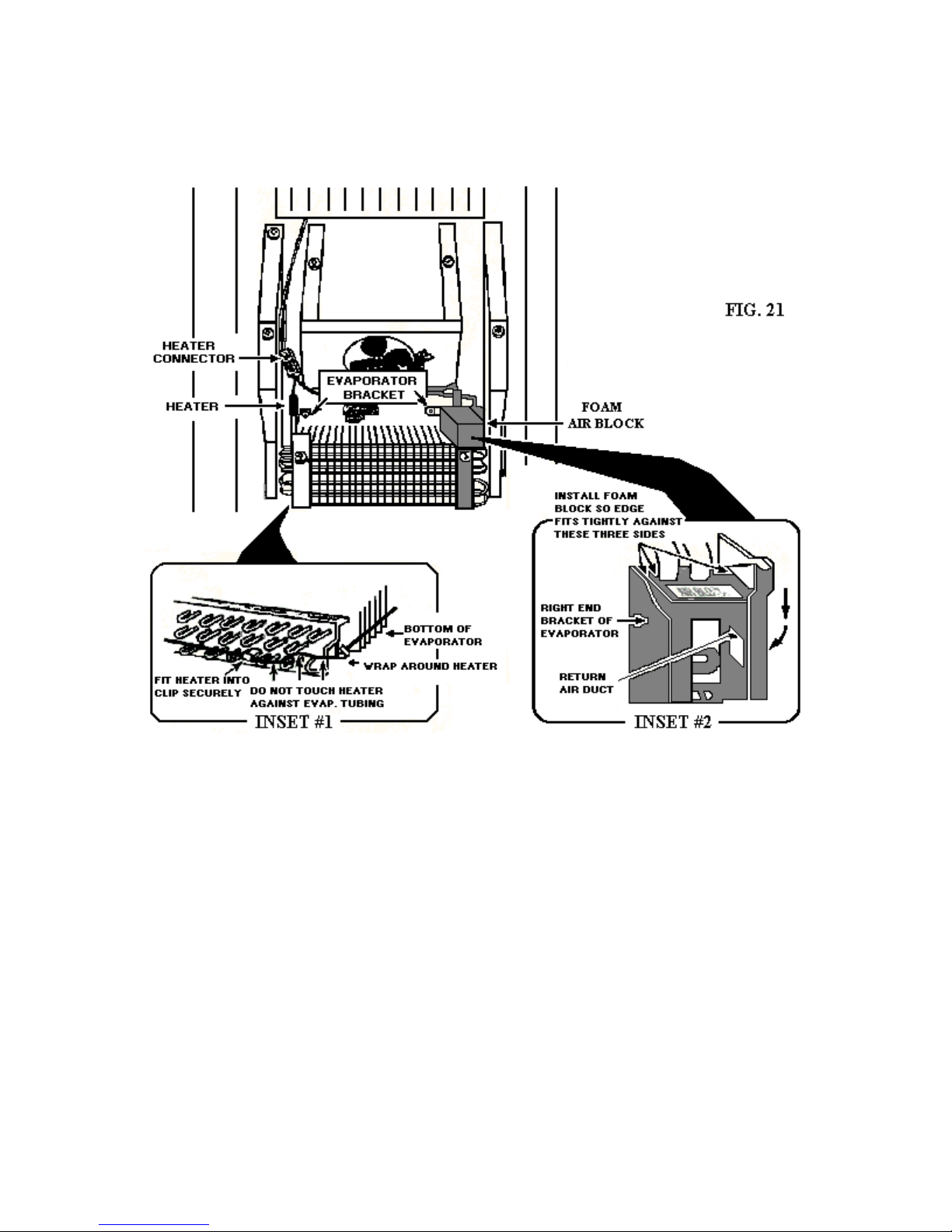
Installing a New Defrost Heater
1. Position the defrost heater so the black wire and the wire connector are to the left.
2. Spread the heater apart far enough to fit over the side clips.
3. Bend the bottom tabs securely around the heater.
4. Snap the heater into the side clips on both sides of the evaporator. Be sure the heater does not
touch any of the evaporator tubing.
5. Carefully rotate the bottom of the evaporator back into position and hang it on the lower center
hook on the freezer liner so the top bracket holes are aligned with the mounting holes in the
freezer liner.
6. Place the foam air-block at the right rear corner of the liner at the top of the evaporator. Form the
holes in the air-block around the tubing.
7. Slide the air-block down to make a tight seal between the evaporator bracket and the back and
side walls of the freezer liner. When the air-block is in the proper position, it should cover the
right evaporator bracket mounting screw.
8. Insert the right lead of the defrost heater into the wire connector hole so it locks in place.
22
Page 23
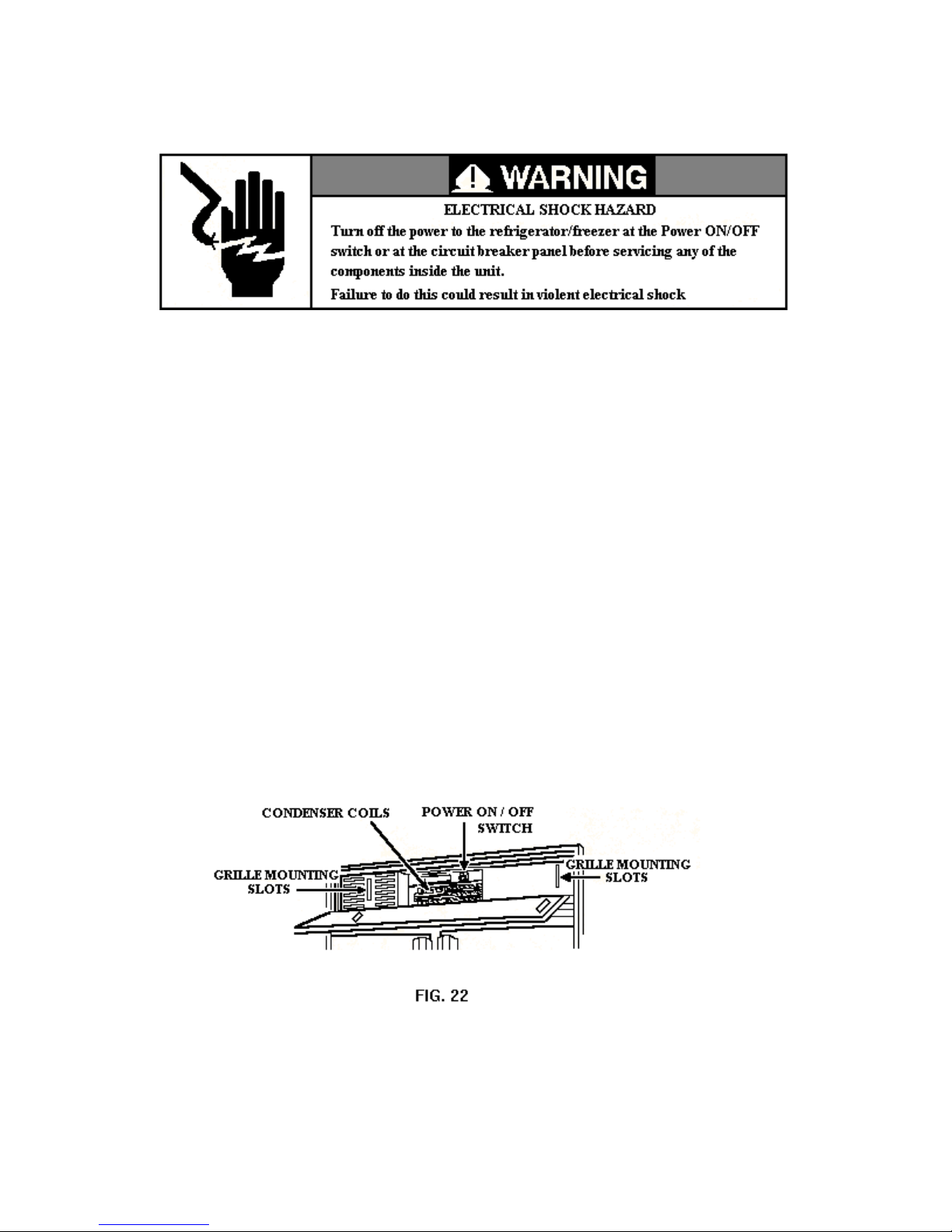
COMPONENTS ON TOP OF THE UNIT
The components that are accessible on the top of the unit are:
• The power switch
• Defrost timer
• Run capacitor
• Water fill valve
• Condenser compartment
Unit Compartment Access
1. Grasp the decorative grille insert and slide it up to remove it from the grille mounting slots.
23
Page 24
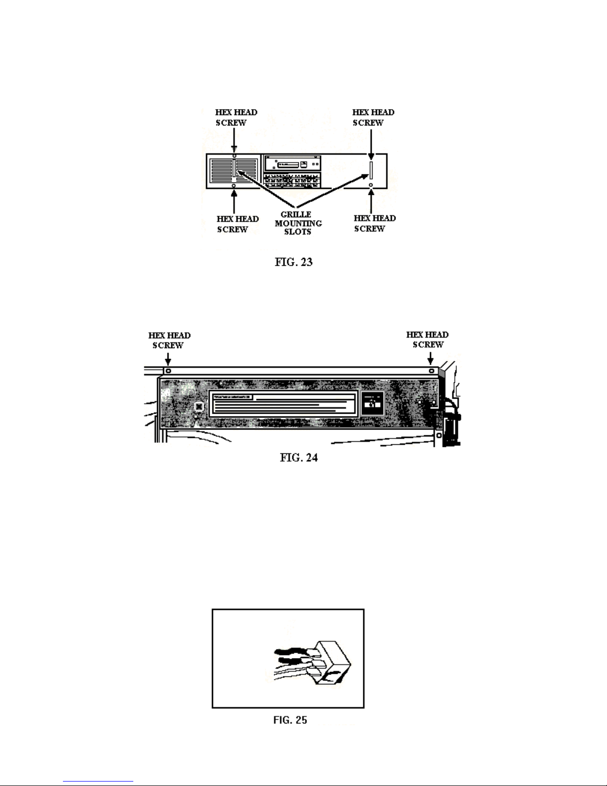
Remove the four hex head screws securing the top grille to the mounting brackets.
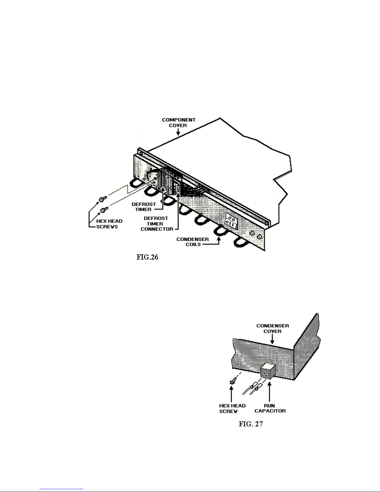
Servicing the Power On / off Switch and Defrost Timer
1. Remove the two hex head screws securing the compartment assembly cover to the component
cover.
2. Rotate the component assembly cover forward so the various components are accessible.
Remove the Power On/Off Switch
The power switch is located on the component assembly cover.
24
Page 25
1. Press the flexible arms against the switch body and push the switch out of the cutout.
2. Disconnect the four wires from the power switch terminals.
3. When installing a new power switch, slide the connectors from the power cord onto terminals six
and three of the switch. Slide the two remaining onto terminals two and five.
Removing the Defrost Timer
The defrost timer is located on the component assembly cover.
1. Remove the two hex head screws securing the defrost timer to the component cover.
2. Unplug the wiring harness connector from the defrost timer.
Removing the Run Capacitor
The run capacitor is located on the left side of the
component cover.
1. Remove the hex head screw securing the run
capacitor to the side of the compartment cover.
2. Disconnect the two wire connectors from the
run capacitor.
25
Page 26
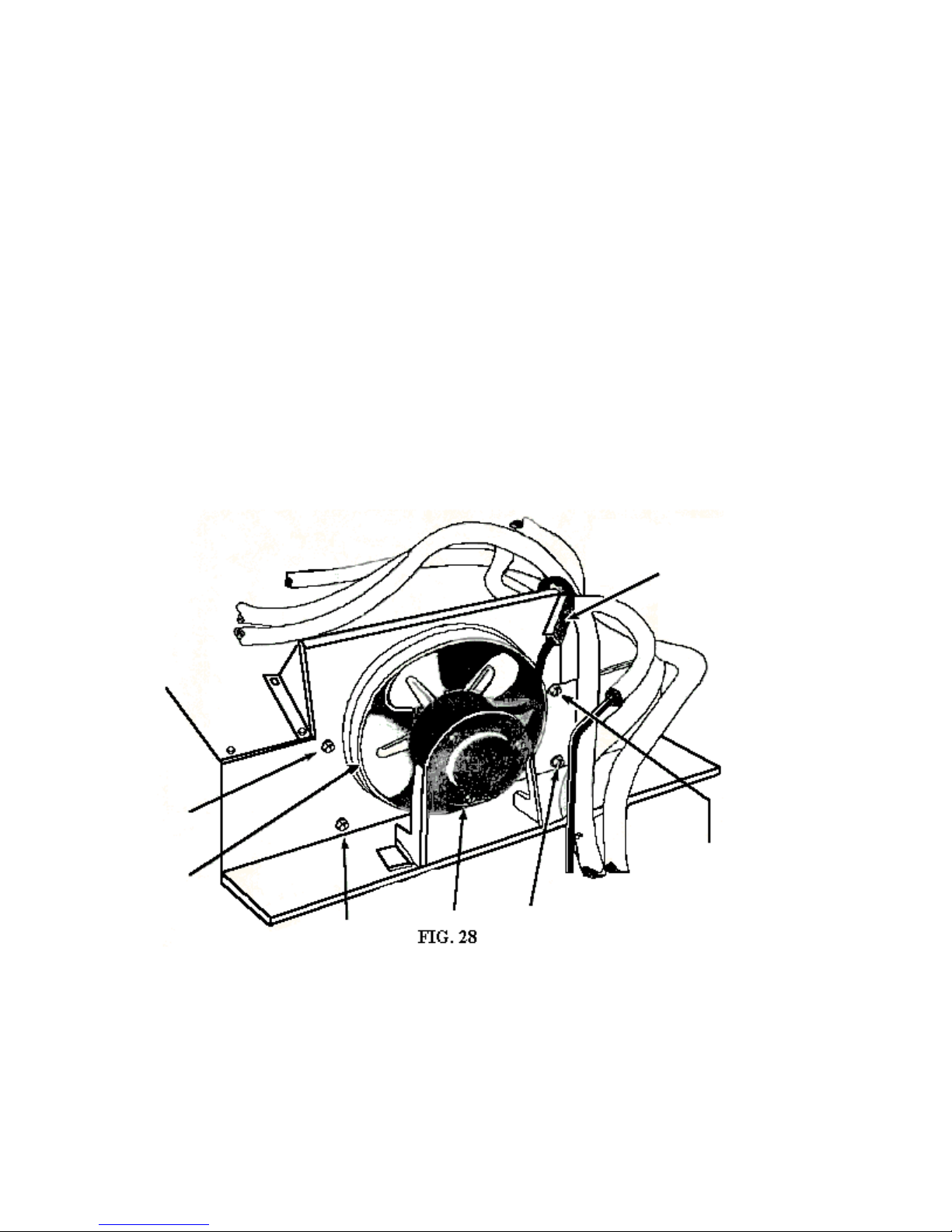
Servicing the Condenser Fan Motor
With the service tray pulled out the condenser fan motor can be serviced.
1. Remove the two hex head screws at the top of the fan shroud.
2. Loosen, but do not remove the three hex head screws securing the fan shroud flange to the condenser cover.
3. Slide the fan shroud off the condenser cover and set it aside.
4. Disconnect the wires from the fan motor terminals.
5. Remove the three hex heads screws securing the fan motor to the mounting bracket.
6
. Remove the nut securing the fan blades to the motor shaft.
26
Page 27
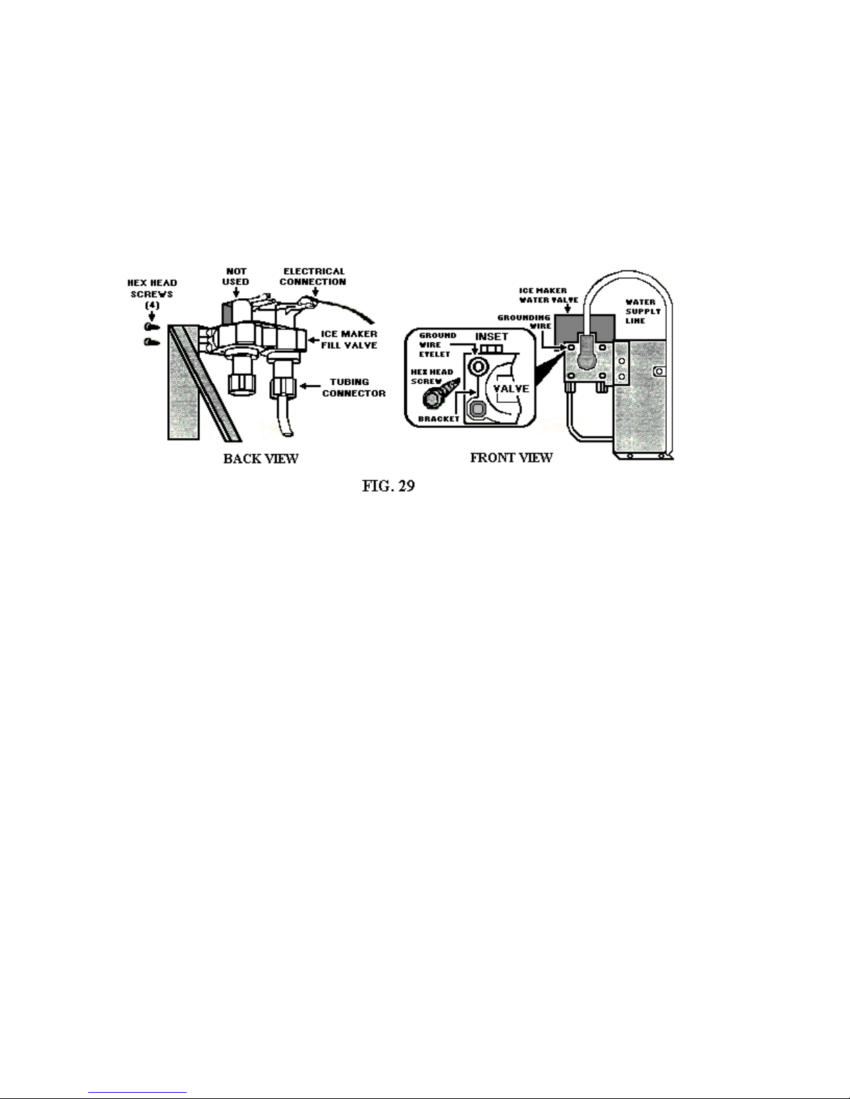
Servicing the Dual Water Supply Valve
The saber valve for the ice maker is located on a mounting bracket to the right of the component
compartment at the top of the unit. Be sure to turn off the water supply to the water fill valve before
doing any service to the valve.
1. Disconnect the copper water supply line from the valve assembly.
2. Remove the two hex head screws that secure the valve assembly to the mounting bracket.
3. Disconnect the plastic water line connector and tube from the valve.
4. Disconnect the two-wire connector from the valve’s solenoid terminal.
27
Page 28
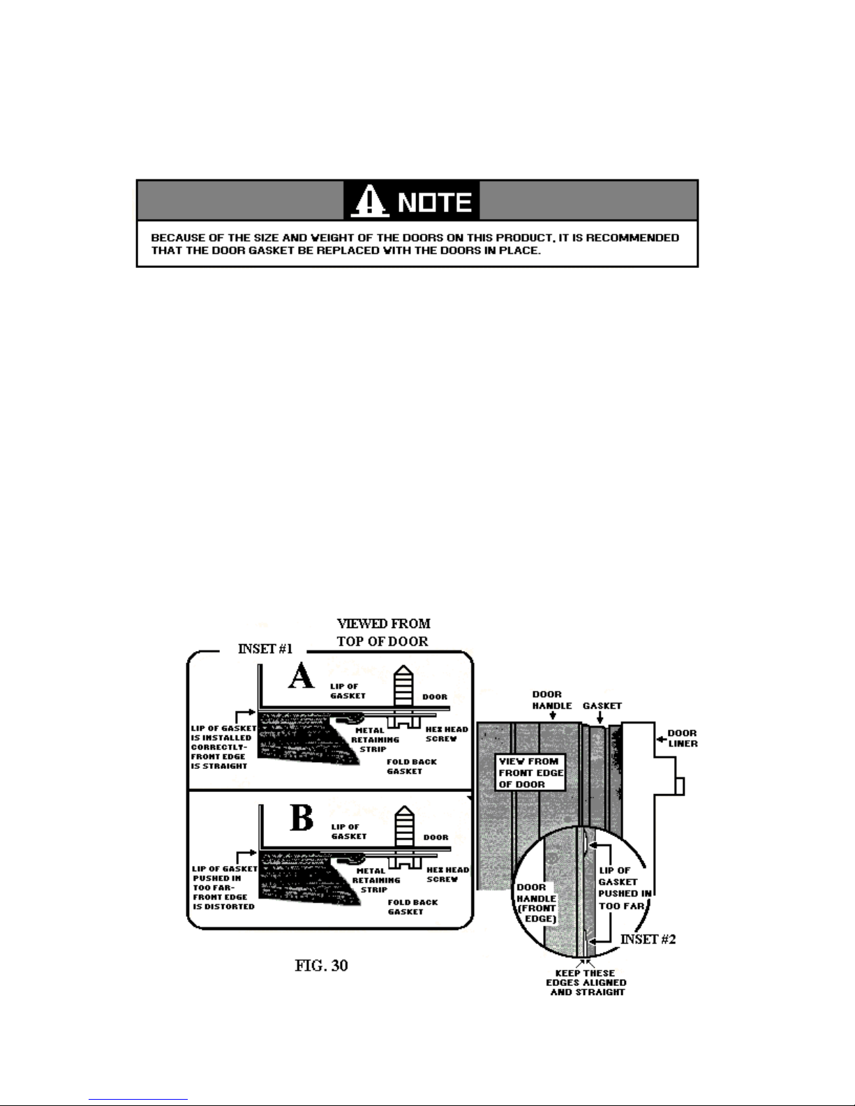
DOOR ASSEMBLIES
Replacing the Door Gaskets
1. Fold the door gasket back and loosen but do not remove the hex head screws all around the
perimeter of the door.
2. Pull the lip of the gasket out from under the metal retaining strip and remove the gasket.
3. To install the new gasket, begin by sliding the lip under the retainer at the top of the door.
4. Tighten the screw in the top retainer just enough to hold the gasket in place.
5. Install the bottom edge of the gasket under the metal retaining strip in the same manner as the top.
6. Beginning at the center of the gasket on the right side, work toward the top of the door, sliding
the lip under the met al retaining strip, tighten the screws as you go along.
7. Install the lower half of the gasket in the same manner. Follow the same procedure for the left
side of the door.
8. Check the entire gasket to make sure it seals properly and that the door is not warped. It may be
necessary to loosen the screws and adjust the gasket or straighten the door. Be sure to tighten all
of the screws securely when the gasket is properly installed and the door is aligned with the
cabinet.
28
Page 29

TROUBLE SHOOTING AND DIAGNOSIS
GENERAL TROUBLE SHOOTING SITUATIONS
Heavy Warm Load
The amount of warm food placed in the refrigerator affects running time and power consumption.
Generally speaking, when a supply of food is placed in the refrigerator, the unit will operate continuously
until the food has been cooled down to the desired storage temperature. This continuous operation is
normal. In regions where the ambient temperature is relatively high, an excessive warm load may cause
overload cycles.
Excessive Door Openings
The length of time the door is left open and the number of times the door is opened should be held to a
minimum. Excessive door openings will greatly increase running time, power consumption and frost
build-up.
Improper Packaging
Uncovered foods and improper packaging materials and methods cause food to dry out. This reduces the
flavor of the foods and results in an excessive frost build-up. Refer the customer to the OWNER’S
GUIDE which came with the refrigerator.
Warm Room
1. A warm room or other large source of heat ( such as range, heater, hot air duct, sunny window ) can
affect performance. If the room ambient temperature exceeds 100*F, 100% running time can be
expected.
2. At temperatures approaching 120*F, the unit may cycle on the overload.
3. In general, the warmer the room, the greater time and power consumption.
Exterior Sweating
Refrigerators are designed to prevent “runoff” moisture at 90*F and 90% relative humidity. There may
be a thin film of moisture on areas at a lower temperature and relative humidity. This is within design
specifications and is not a fault of construction.
If possible, relocating the refrigerator in a less humid, better ventilated area will normally eliminate most
moisture problems.
29
Page 30
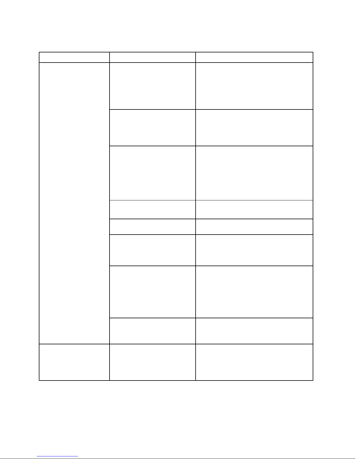
DIAGNOSTIC CHART
PROBLEM POSSIBLE CAUSE TEST PROCEDURE - ACTION
Compressor will not start No power at ON / OFF switch Plug in electrical outlet or turn on breaker.
No power at the compressor Press power switch to ON.
No power at the outlet Check with test lamp or volt meter.
Should supply 110-120 volts AC, 60 HZ.
Thermostat: Turn knob clockwise
a. Turned off Place jumper between terminals. If comp b. Points not closing ressor starts, thermostat is defective and
should be replaced.
Relay or overload Using starting cord, check compressor
Directly. If compressor starts, check relay
And overload individually with ohmmeter
and
Replace one found defective. If compressor
doesn’t start, replace compressor.
Loose connections Check circuit from power source to comp ressor using wiring diagram as guide.
Run capacitor Check capacitor, replace if defective.
Motor windings open, Check windings with ohmmeter. See wiring
shorted or grounded diagram for resistance values. Replace
Compressor if motor is defective.
Timer Timer may be in defrost cycle. Turn
clockwise past 2 o’clock.
Wired wrong.
Check timer and replace if defective.
Compressor stuck Try starting with starter cord. If compressor
won’t start, change compressor.
Compressor runs, but no Moisture restriction Heat frosted area. If frost line moves farther
refrigeration or insuf-
ficient refrigeration. Heavy frost around evaporator
along coil after heating, restriction was prob
ably caused by moisture freeze up. Discharge
-
unit, sweep the system and recharge.
30
Page 31
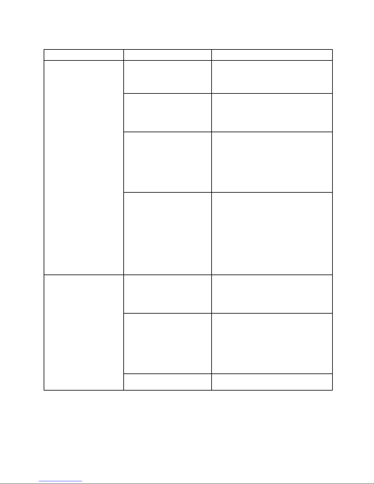
PROBLEM POSSIBLE CAUSE TEST PROCEDURES-ACTION
Compressor runs, but no Permanent restriction First check for moisture restriction.
refrigeration or insuf- Check for crimped or damaged tubing.
ficient refrigeration Repair or replace restricted component.
Low charge or no charge Check for leak. Add leak charge to get
internal pressure. Repair leak or replace
Leaking component.
No capacity or low capacity Check operating wattage and pressure.
compressor. See performance chart for wattage and
high and low side pressures. Do not
judge compressor to have low capacity
until restrictions and low charge have
been ruled out.
Air circulation on high side:
a. Condenser or grille Clean condenser and air passage with
restricted by lint vacuum cleaner.
b. condenser fan motor Disconnect fan motor leads and check
running or running separately. Replace motor if defective.
slowly.
c. Condenser fan motor Put condenser fan motor top cover in
top cover not in place. Place.
Compressor kicks out on High ambient and / or ab- On initial pull-down in high ambient,
overload normal usage. the compressor may cut off on overload.
Instruct customer.
Low or high voltage Check voltage with voltmeter. Voltage
at outlet should be 110 to 120 volts AC
at the moment of start. Low voltage
may cause false start s. High voltage
may cause compressor to overheat.
Correct voltage condition.
Run capacitor Check capacitor. Replace if defective.
31
Page 32
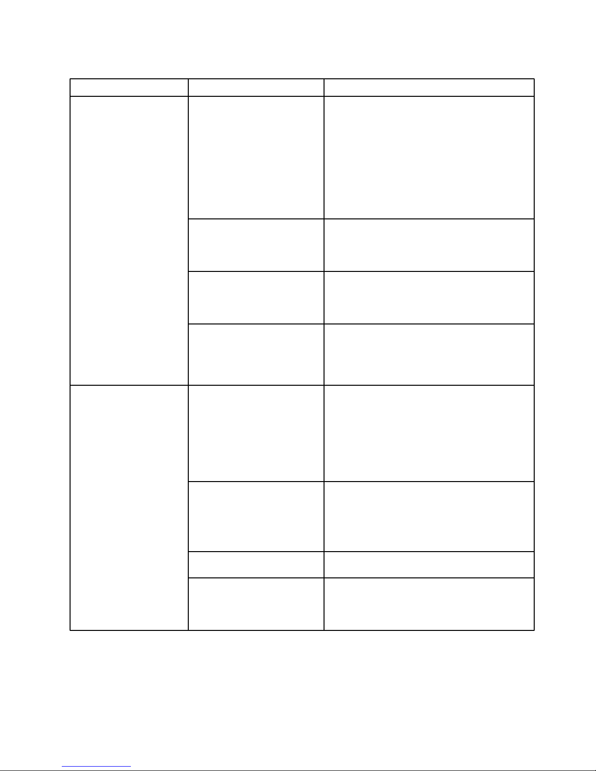
PROBLEM POSSIBLE CAUSE TEST PROCEDURE-ACTION
Compressor kicks out on Air circulation on high side:
overload (continued)
a. Condenser or grille Clean condenser and air passage with vacuum
restricted by lint cleaner.
b. Condenser fan motor Disconnect fan motor leads and check separ Running or running ately. Replace motor if defective.
Slowly.
c. Condenser fan motor Put condenser fan motor top in place.
Top not in place.
Relay and / or overload Replace with parts known to be good.
Motor windings shorted Check windings with ohmmeter. See wiring
Diagram for resistance values. Replace
Compressor if motor is defective.
Over charge Check for high wattage and frosted suction
Line. Evacuate and recharge with correct
charge.
Freezer compartment too Thermostat:
warm. a. Set too warm Turn knob to higher setting.
b. Sensing tube not prop- See that sensing tube is properly positioned.
erly positioned
c. Out of calibration or Check thermostat for cut-in and cut-out
Not functioning temperatures. Replace if necessary.
Interior air circulation
a. Fan Check evaporator fan. Replace if defective.
b. Restriction in ducts Check for and remove obstruction in ducts.
Abnormal usage Instruct customer.
Bad door seal or door Adjust door to obtain proper seal.
not closing. Instruct customer to make sure door closes
completely.
32
Page 33
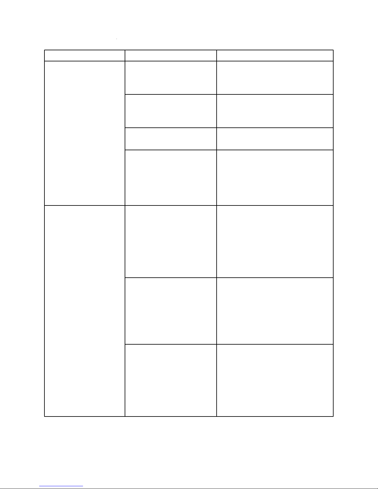
PROBLEM POSSIBLE CAUSE TEST PROCEDURE-ACTION
Freezer compartment too High ambient temperature Locate in area our of direct rays of the
warm (continued) sun and away from heat registers or
Other source of heat.
Cabinet light Check to make sure door switch is
closed. Replace or adjust switch if
necessary.
Excessive frost on evapo- check items under complaint, “incom rator. plete defrosting.”
Unit:
a. Compressor won’t Check items under complaint, “Com Run pressor won’t run.
b. Compressor runs Check items under complaint, “Com continuously pressor runs, but no refrigeration or
Insufficient refrigeration.
Refrigerator compart- Motorized Air Door: Check for a motor winding resistance of
ment too warm 8800 ohms between the BE/Y and W
a. Baffle closed wires or the Y/R and W wires. If the
meter reading shows “open” for both
BE/Y and Y/R wires, replace motor.
b. Baffle is stuck closed Check for iced door. Remove ice and
eliminate moisture entering due to air
leak.
Electronic control board:
a. Set too warm Turn knob to colder position.
b. Baffle stuck closed Check for 120 volts between the OR/W
and W wires at circuit board plug.
NOTE: Use static control gloves when
handling electronic control board.
Thermistor:
a. Sends wrong or high Check resistance for given temperature
resistance signal to at GY wires. An open or infinite resis control board. tance reading closes the door. Replace
the thermistor.
b. Others, same as Same as items under, “Freezer compart “Freezer compart- ment too warm.”
ment too warm
33
Page 34
PROBLEM POSSIBLE CAUSE TEST PROCEDURE-ACTION
Freezer compartment Thermostat:
too cold a. Set too cold Turn knob to warmer position
b. Sensing tube not properly See that sensing tube is properly
positioned positioned.
c. Out of calibration or not Check thermostat for cut-in and cut-out
functioning temperatures. Replace if necessary.
Refrigerator compart- Motorized Air Door: Check for a motor winding resistance of
ment too cold
a. Baffle open 8800 ohms between the BK/Y and W
Wires. If the meter reading shows “open”
for both BK/Y and Y/R wires, replace
Motor.
b. Baffle is stuck open Check for iced door. Remove ice and
Eliminate moisture entering due to air
leak.
Electronic control board:
a. Set too cold Turn knob to warmer position.
b. Baffle stick open Check for 120 volts between the OR/W
and W wires at the circuit board plug.
NOTE: Use static control gloves when
handling control board.
Thermistor:
a. Sends wrong or high Check resistance for given temperature
resistance signal to at GY wires. An open or infinite
control resistance reading closes the door.
Replace the thermistor.
External Sweating Freezer heater inoperative Check heater with ohmmeter
Mullion heat loop restricted Check sealed system for restriction.
Bad door seal or door not Adjust door for proper seal.
closing
34
Page 35
PROBLEM POSSIBLE CAUSE TEST PROCEDURE-ACTION
Internal Sweating Abnormal usage Instruct customer to cover foods and
liquids.
Door Seal Adjust door for proper seal.
Insufficient air circulation Make sure return air flow is not
restricted.
Increase cold air flow by operating
refrigerator compartment as cold as
possible without freezing food.
Incomplete defrosting or Limit switch Check bimetal defrost control. If
high cabinet tempera- bimetal opens too soon defrost will
tures during defrost . be incomplete and frost will accumulate.
If bimetal is stuck closed or opens too
late, high cabinet temperature will
result. A loose bimetal may cause the
defrost heater to stay on too long.
Change bimetal if defective.
Timer
Check timer for proper operation. Timer
should initiate 21 minute defrost cycle
every 10 hours. Replace if defective.
Defrost Heater Check defrost heater with ohmmeter.
Inoperative defrost heater will result in
frost and ice accumulation on
evaporator. Replace if defective.
Drain clogged Clogged drain may result in ice buildup
in evaporator. Clear drain system.
Taste and odor Odorous food Instruct customer to keep food covered
and clean refrigerator and freezer with
solution of baking soda and water.
Explain how odor and taste of food in
refrigerator can be absorbed by ice
cubes
in freezer due to internal air circulation.
Hot plastic
Check for a heater in contact with
plastic
or sealing compound, which may cause
odor.
35
Page 36
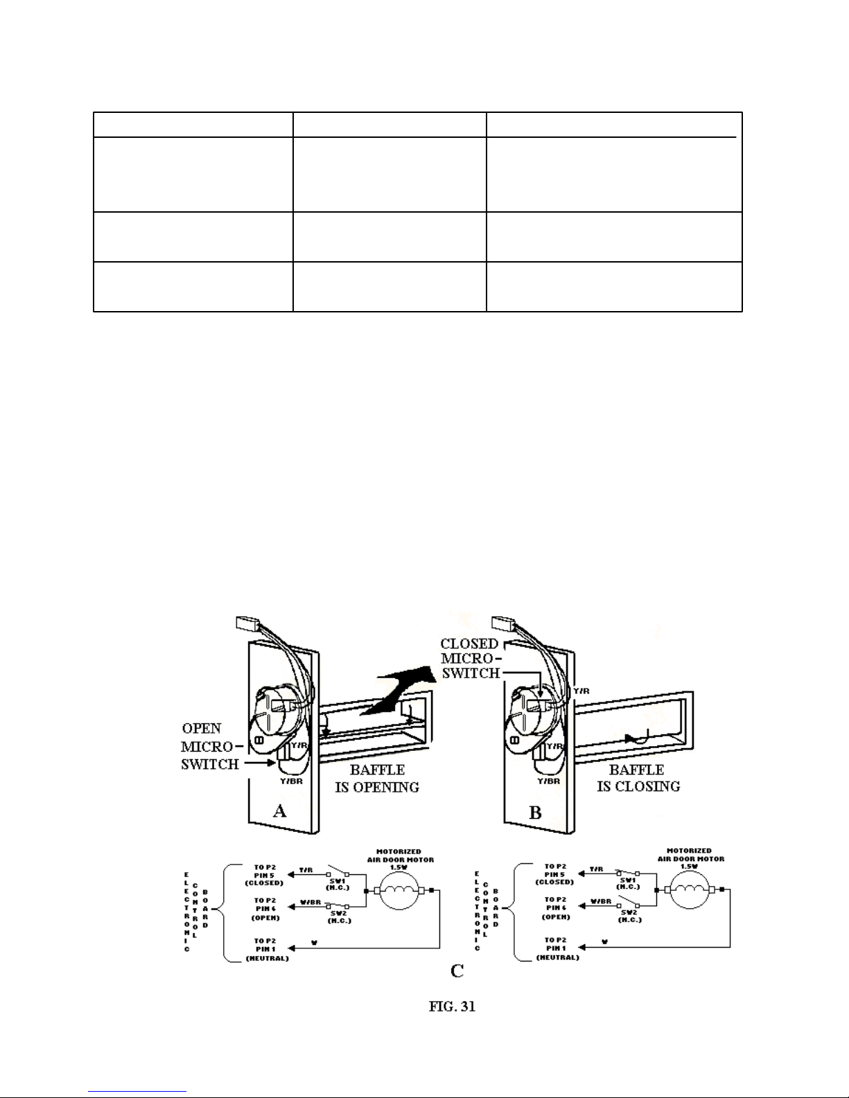
PROBLEM POSSIBLE CAUSE TEST PROCEDURE-TEST
Door will not close or will Gasket binding Adjust hinges, add shims if necessary.
Not seal Lubricate face of gasket on hinge side
With parawax.
Door warped Loosen retainer screws and rack door
To fit cabinet.
Cabinet racked Level cabinet; make sure cabinet is
setting solidly at all four corners.
THE MOTORIZED AIR DOOR
The electronic control board, located inside the refrigerator control cover, controls the operation of the
motorized air door, the thermistor and the evaporator fan motor.
120 volts AC is supplied to the electronic control board through the BK wire and operates the circuit as
follows:
Switch SW2 (Fig.31-C). The motor rotates 90* from the “open” position (Fig.31-B) to the
“closed” position where it contacts SW2 which opens and parks the motor.
1. To open the baffle: 120 volts AC is supplied to the baffle motor through the Y/R wire and
switch SW1 (Fig.31-C). The motor rotates 270* from the “closed” position (Fig.31-A) to the
open” position where it contacts SW1 which opens and parks the motor.
2. To close the baffle: 120 volts AC is supplied to the baffle motor through the W/BR wire and
3. 120 volts AC is supplied through the OR/W wire to the electronic control board which
energizes the evaporator fan motor and supplies low voltage to the thermistor.
36
Page 37
CHECKING CONTINUITY
To make component or wiring measurements, set an ohmmeter’s RANGE switch at R x 1 (unless directed
otherwise.) For all “ground” measurements, set the RANGE switch to R x 10k. Insert the ohmmeter
probes into the plug pins or against the component terminals as directed in the procedure.
COMPONENT TEST PROCEDURE METER READINGS
THERMISTOR The thermistor can be tested by
Temperature (*F) = Resistance(Ohms)
measuring the resistance between
The GY wires at the thermistor con- 35*F = 8240 - 8926 65*F = 3628 - 3930
nector or at the DC connector of the 40*F = 7143 - 7739 70*F = 3189 - 3455
electronic control board. Making the 45*F = 6209 - 6727 75*F = 2810 - 3044
test at the board is an easy way to 50*F = 5410 - 5860 80*F = 2480 - 2687
check out the thermistor wiring har- 55*F = 4724 - 5118 85*F = 2194 - 2376
ness. The “Meter Readings” show 60*F = 4235 - 4479 90*F = 1945 - 2107
the thermistor resistance over a
range of temperatures.
DEFROST Disconnect the defrost heaters wire The ohmmeter should indicate approxi HEATER connector from the wiring harness. mately 19 ohms to 20 ohms.
Touch the ohmmeter probes to the
Connector pins.
Ground Test: Touch one probe to Should indicate an “open’ circuit for both
the chassis and the other to each pins. Any resistance indicates a short
connector pin. circuit.
BIMETAL Make sure that the freezer is cold
Enough to close the bimetal con tacts. The bimetal contacts close
At approximately 20*F +/- 8*F and
open at approximately 50*F +/- 8*F.
Disconnect the 2-pin bimetal con- Continuity if the evaporator temperature
nector (PX and BR wires) from the is below 12*F. No continuity if the
wiring harness. Touch the ohmmeter evaporator temperature is above 56*F.
Probes to the pins on the ends to the
Wires.
EVAPORATOR Disconnect the wire terminals from The ohmmeter should indicate between
FAN MOTOR the motor. Touch the ohmmeter 40 ohms and 80 ohms.
probes to the motor terminals.
Ground Test: Touch one probe to Should indicate an “open” circuit.
the chassis and the other to each Any resistance indicates a short circuit
wiring connector.
37
Page 38
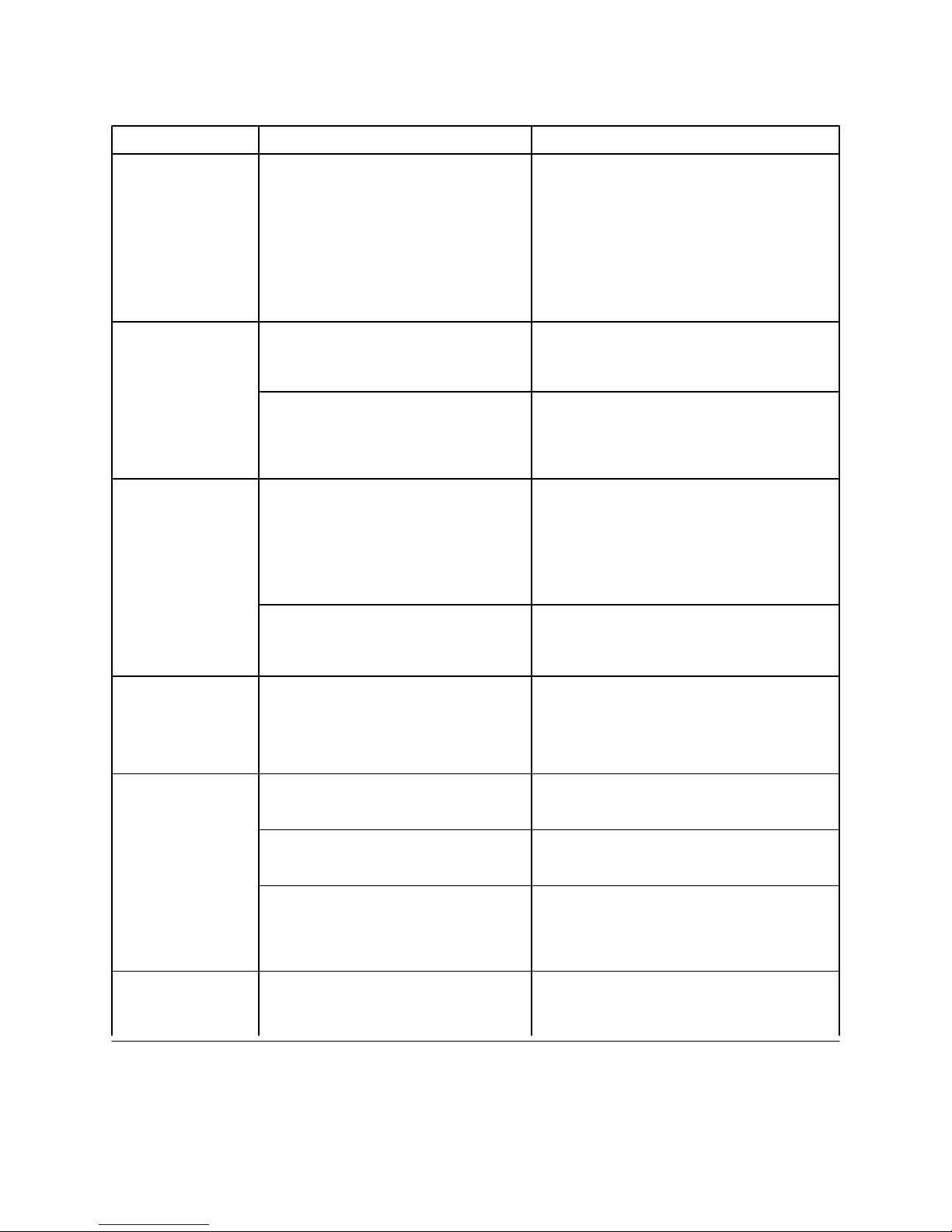
COMPONENT TEST PROCEDURE METER READING
MOTORIZED Disconnect the wire terminals from Approximately 8800 ohms between the
AIR DOOR the motor and touch the ohmmeter W/BR and W wires OR the Y/R and W
probes to the connector pins as fol- wires.
lows:
1. Y/BR and W wires
2. Y/ R and W wires
ICE MAKER Disconnect the solenoid wiring con- The ohmmeter should indicate
FILL VALVE nector. Touch the ohmmeter probes approximately 270 ohms.
to the solenoid terminals.
Ground Test: Touch one probe to Should indicate an “open” circuit for both
the chassis and the other to each terminals. Any resistance indicates a
solenoid terminal. short circuit.
CONDENSER Disconnect the condenser fan motor The ohmmeter should indicate between
FAN MOTOR connector from the wiring harness. 115 ohms and 450 ohms.
Touch the ohmmeter probes to the
motor wire connector pins.
Ground Test: Touch one probe Should indicate an “open” circuit for each
to the chassis and the other to each connector. Any resistance indicates a
motor wiring connector. short circuit.
THERMOSTAT Disconnect the thermostat wiring With the thermostat turned fully clock connector. Touch the ohmmeter wise, the ohmmeter should show
probes to the thermostat connector “continuity.” Fully counter clockwise
pins. rotation should show “no continuity.”
COMPRESSOR Touch the ohmmeter probes to the The ohmmeter should indicate between
S and C connector pins. 4 ohms and 22 ohms.
Touch the ohmmeter probes to the The ohmmeter should indicate between
M and C connector pins. 1 ohm and 4 ohms.
Ground Test: Touch one probe Each connector should indicate an “open”
to the chassis and the other probe to circuit. Any resistance indicates a shorted
the S, M and C connectors. winding.
OVERLOAD Touch the ohmmeter probes to the The switch is normally closed (N.C.),
PROTECTOR two terminals. so the ohmmeter should show continuity
(0 ohms).
38
Page 39
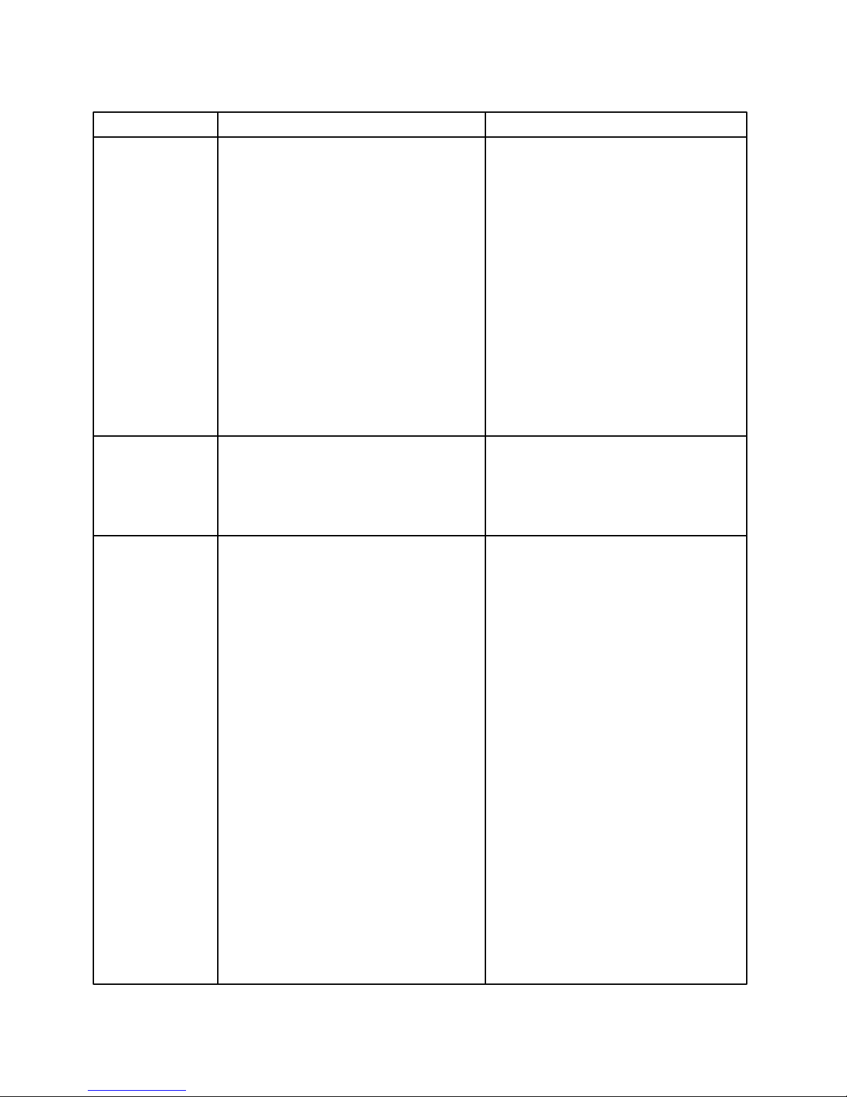
COMPONENT TEST PROCEDURE METER READING
PTC START The PTC Start Relay cannot be
RELAY tested. To determine its reliability,
use the following procedure:
1. Measure the R and W wires at
The compressor for 120 volts AC.
2. Check the overload relay to make
sure there is continuity through
It. (Use the previous test proced ure.)
3. Test the run capacitor. (Use the
following test procedure.)
4. Use a test cord and start the com pressor. If it starts, and the pre ceding checks are okay, the relay
Is defective.
RUN Disconnect the wires and touch the The ohmmeter reading should peak
CAPACITOR ohmmeter probes to the two terminals. and then drop. Reverse the test
probes on the terminals and the
Same results should occur.
TIMER To test the timer, perform the follow ing steps:
NOTE: The 1. Use a screwdriver and manually
production turn the time clockwise until you
timer (Paragon) hear a “click.” This will place
has a 10 hour the timer in the “defrost” position
cumulative if the refrigerator was running,
run time with the compressor and fans will
a 21 minute turn off.
Defrost 2. Unplug the unit.
duration. 3. Disconnect the 4 wire connector
The service re- from the timer.
placement timer 4. Set the ohmmeter to the Rx10k.
(Mallory) has
an 8 hour Checking the Motor:
cumulative run
time with a 21 1a. Paragon Timer: The motor wind- Paragon Timer - When you first touch
minute defrost ings have a capacitor connected the terminals the meter should momen duration. In series. Use the same procedure tarily deflect and show continuity.
that you would use for checking a
capacitor. Momentarily touch the
probes to terminals PK and R,
then reverse the probes and touch
the terminals again.
39
Page 40
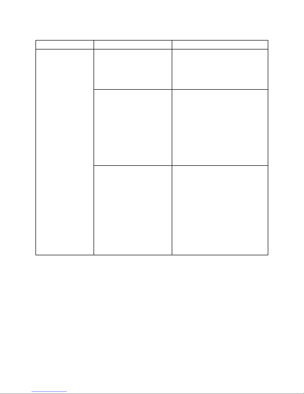
COMPONENT TEST PROCEDURE METER READING
TIMER
(Continued) 1b. Mallory Timer: Touch the Mallory Timer - the meter should
meter probes to timer ter- read 6000 ohms to 9000 ohms.
minals PK and R (motor
windings).
The Defrost Mode
1. Set the ohmmeter to Rx1
scale and zero the meter.
2. Touch the meter probes The meter should read “ zero” resistance
to timer terminals PK and (contacts closed.) If it reads anything
BK (switch contacts.) else, replace the timer.
3. Touch the meter probes The meter should read “infinity” (con terminals BK and OR tacts open.) If it reads anything else,
(switch contacts.) replace the timer.
Cooling Mode
1. Use a screwdriver and
Manually advance the
Time 1/4 turn.
2. Touch the meter probes The meter should read “zero” resistance
to timer terminals BK (contacts closed.) If it reads anything
and OR (switch contacts.) else, replace the timer.
3. Touch the meter probe The meter should read “infinity” (con to timer terminals PK tacts open.) If it reads anything else
and BK (switch contacts.) replace the timer.
40
Page 41
R134a REFRIGERANT
SERVICE INFORMATION
This product uses R134a refrigerant. This refrigerant requires synthetic Ester Oil in the compressor. This cooling
system does not tolerate contamination from any of the following:
• Other Refrigerants
• Moisture
• Petroleum-based Lubricants
• Silicone Lubricants
• Cleaning Compounds
• Rust Inhibitors
• Leak Detection Dyes
• Any Other Type of Additive
As a result the following precautions should be observed
• Use equipment dedicated to R134a sealed system only.
• Do not leave a replacement compressor open to the atmosphere for more than 10 minutes.
• Always replace the filter-drier when performing any repairs on the sealed system.
• Use only 134a refrigerant for back flushing and sweep procedures.
• If the rubber plugs on the service replacement compressor appear to have been tampered with or
removed, DO NOT USE THE COMPRESSOR. Get another one.
• The filter-drier MUST be cut from the sealed system. Never un-braze the filter-drier from system
tubing. Applying heat will drive moisture back into the sealed system.
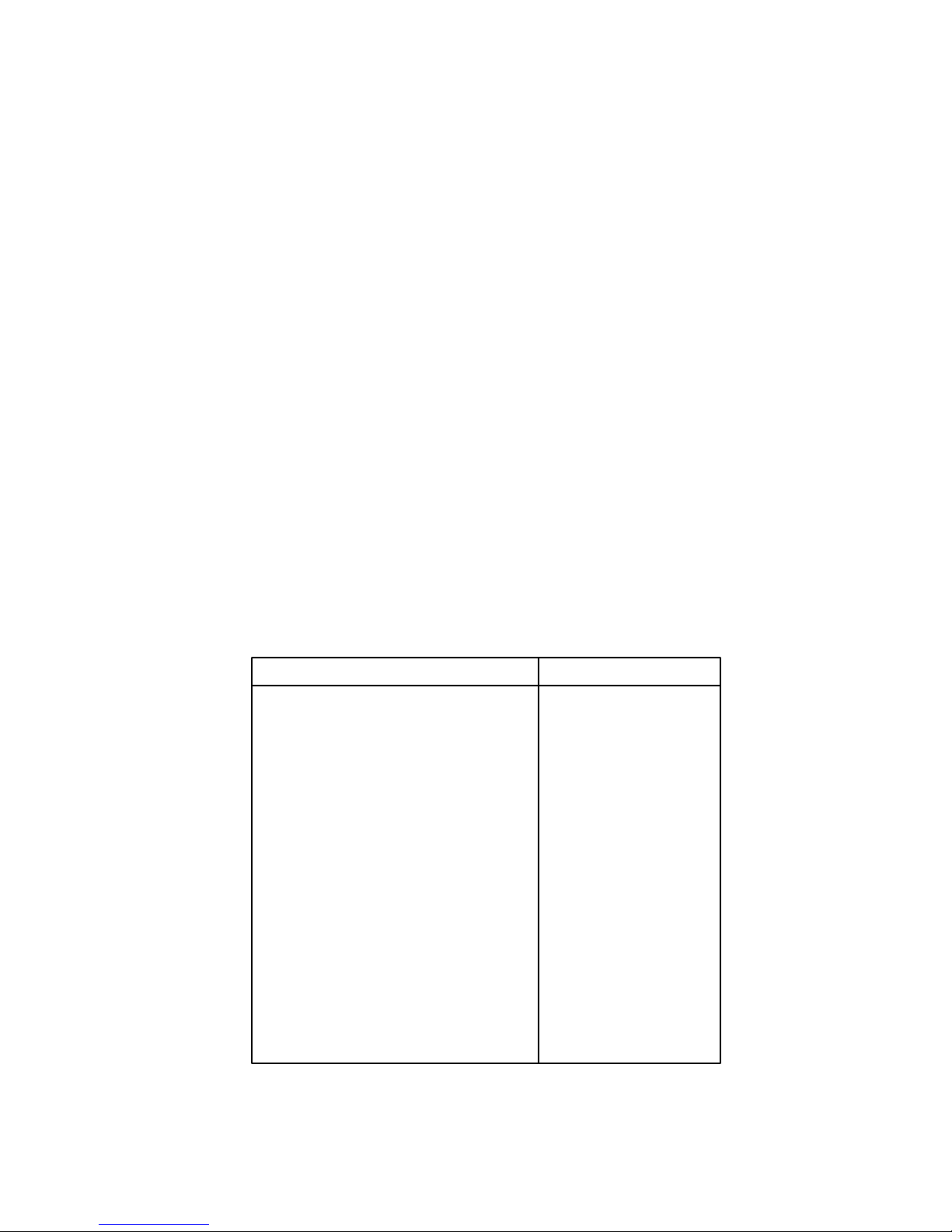
HEALTH AND SAFETY HANDLING 134a
Allowable Overall Exposure Limit 1,000 ppm
Vapor Exposure to Skin No Effect
Liquid Exposure to Skin Can Cause Frostbite
Vapor Exposure to Eyes Very Slight Irritation
Liquid Exposure to Eyes Can Cause Frostbite
Above Minimum Exposure Limit Can Cause Asphyxiation.
Tachycardia and Cardiac
arrhythmias.
Safety and Handling Wear appropriate Skin and
Eye protection. Use
adequate Ventilation.
Spill Management Remove or Extinguish Igni tion or Combustion Sources.
Evacuate or Ventilate Area.
Fire and Explosion Hazards May Decompose if contact
with Flames and Heating
elements. Container May
Explode IF Heated Due to
Pressure Rise. Combus ion Products are Toxic.
Storage Conditions The Procedures/Rules for
R12 also Apply to 134a.
Disposal Procedure Reclaim
41
Page 42
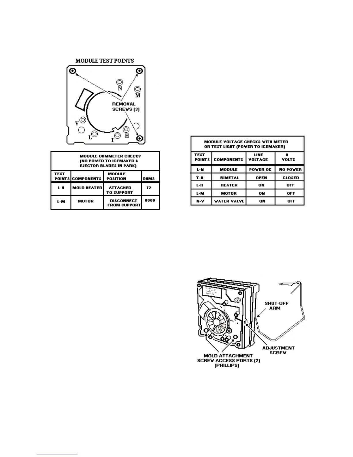
MODULAR ICE MAKER SERVICE
SHEET
SPECIFICATIONS
Mold Heater 185 watts. 72 ohms
Thermostat close 17°F ± 3°
(Bimetal) open 32°F ± 3°
Water fill 140cc, 7.5 sec.
Motor 1.5 watts, 8800 ohms
Module stamped circuit.
plug in connectors
Cycle one revolution
(Ejects & water fill)
For 120 models
Service Procedures
Cover Pull water adjustment knob first and snap off cover
index knob and reinstall in same position for same
water fill.
Module motor and support assembly-
Insert Phillips driver in access ports in module-loosen
both screws – disconnect shut-off arm –pull mold
from support assembly.
Shut-off arm Pull out from support – reinstall to full depth.
Mold and heater Remove module motor and support assembly.
Bimetal-
Remove module motor and support assembly – pull
out retaining clips with bimetal.
Fill cup-
Remove module motor and support assembly –
remove ejector blades and shut-off arm – pull fill cup
from mold.
Ejector blades or stripper-
Remove module motor and support assembly. When
re-installing ejector blades, realign “D” coupling with
module cam.
Water Level adjustment
Turning the screw clockwise decreases the water fill.
½ turn equals 20cc or 12 sec.
Full turn equals 40cc or 24 sec.
Maximum adjustment is one full turn either
direction. Additional rotation could damage
Module.
42
Page 43
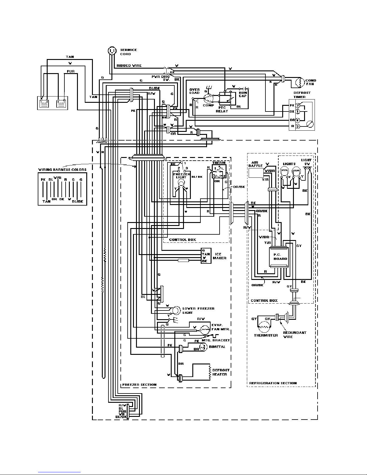
43
Page 44
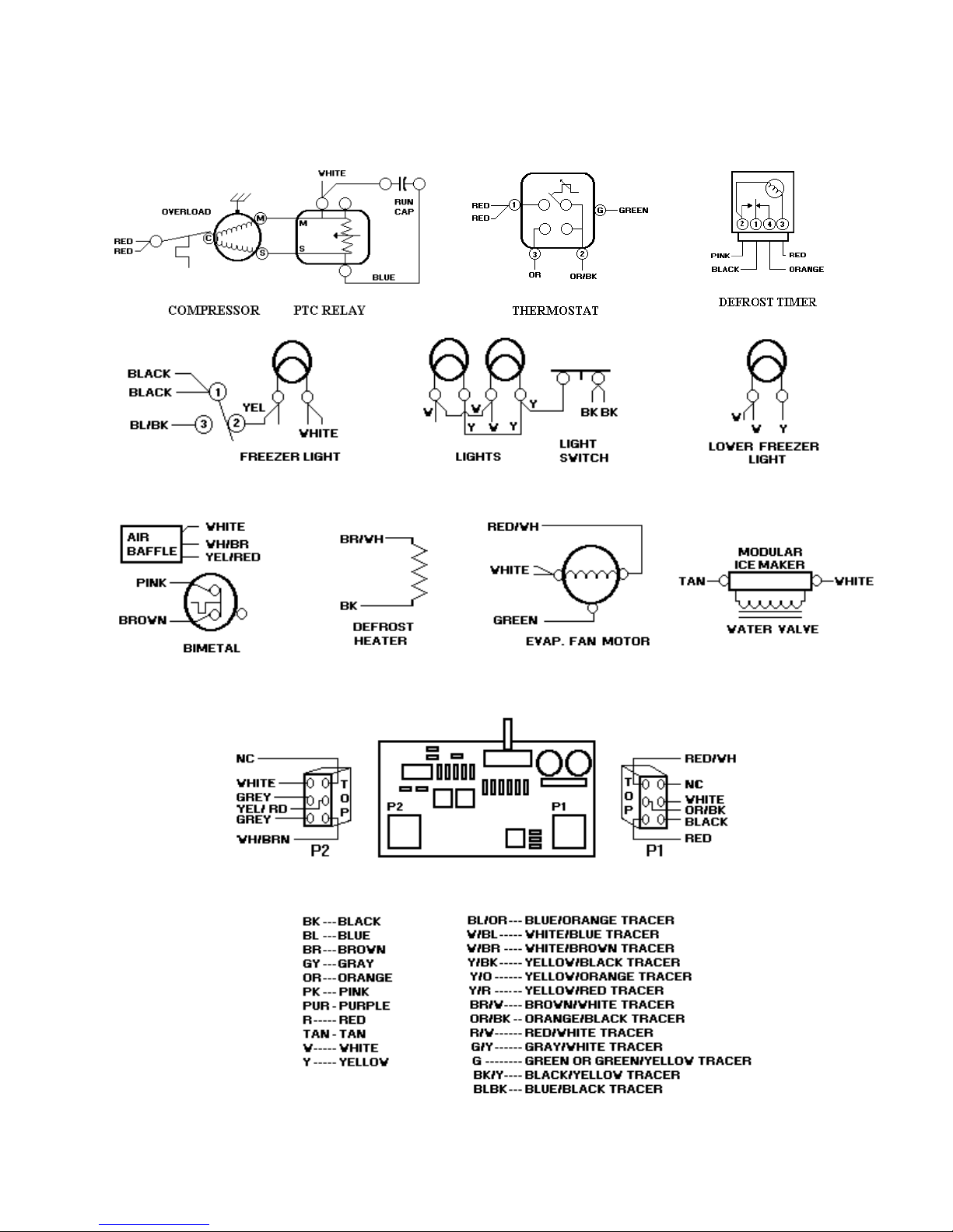
REFRIGERATOR COMPONENTS
44
Page 45
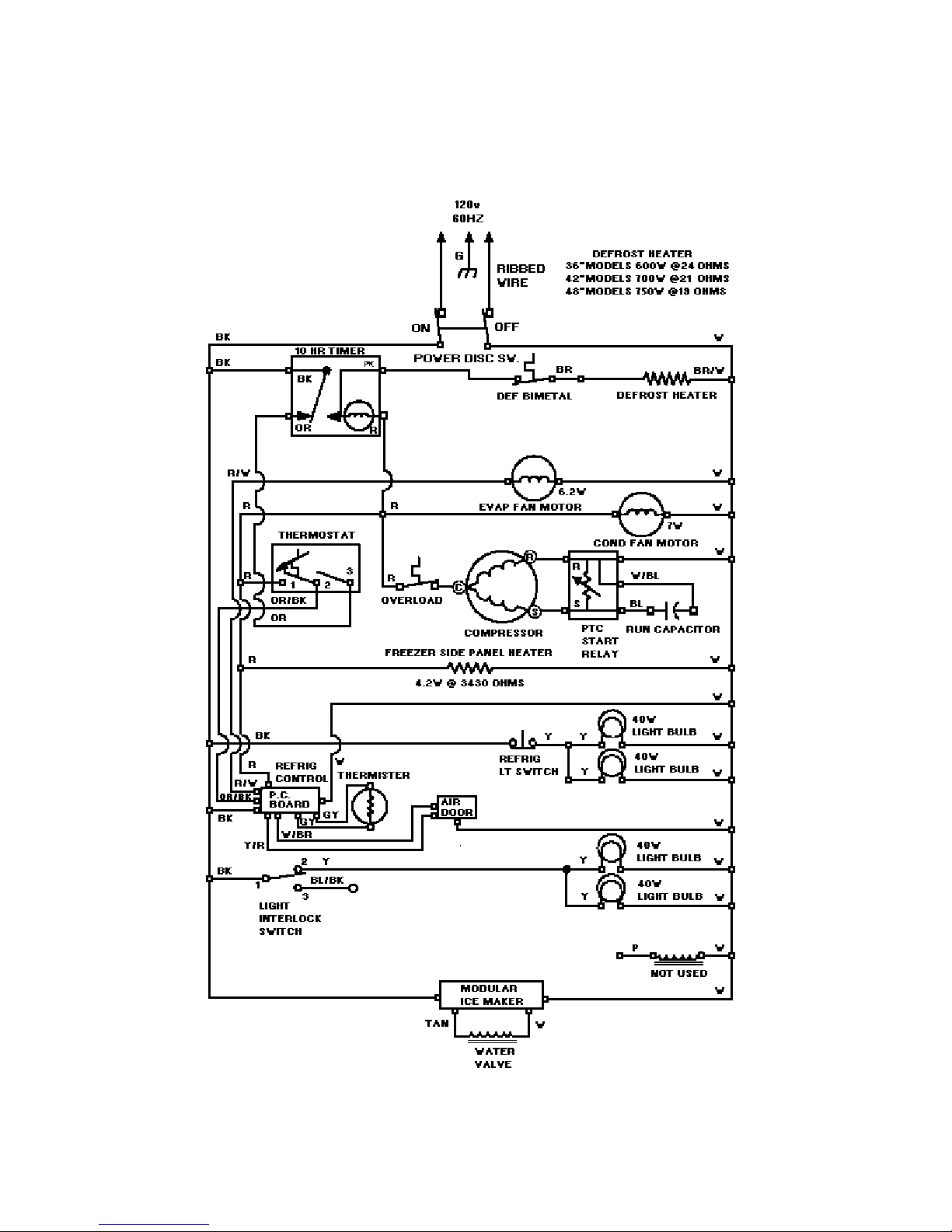
WIRING DIAGRAM
45
Page 46
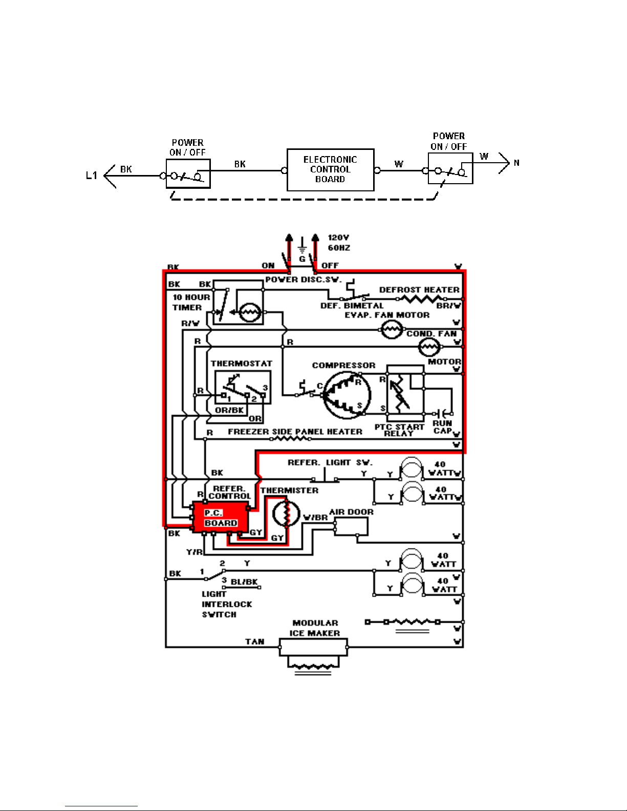
LINE CIRCUITS ( # 1 )
The Cooling Cycle
1. Unit Plugged in, Electronic Control Board Energized (Also During Defrost).
WATER VALVE
46
Page 47
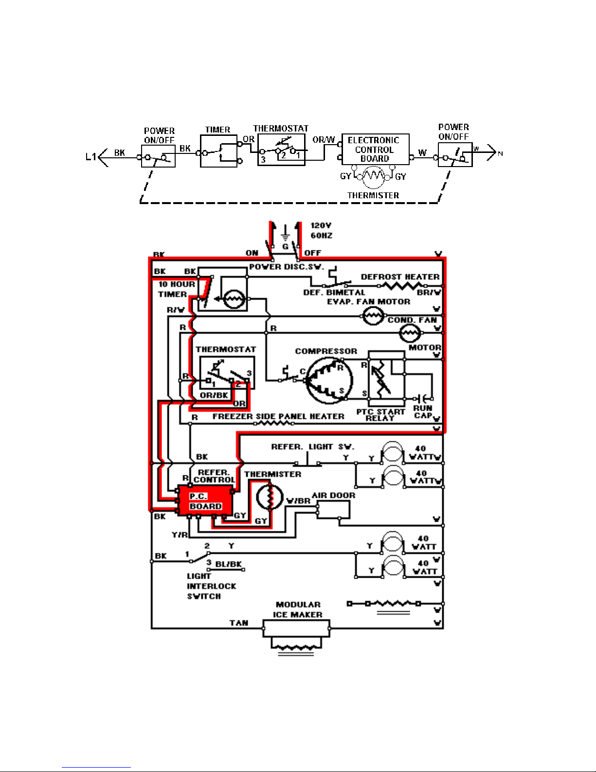
LINE CIRCUITS (# 2)
The Cooling Cycle
2. Freezer Thermostat Turned On. But Satisfied -- Low Voltage To Thermister
WATER VALVE
47
Page 48
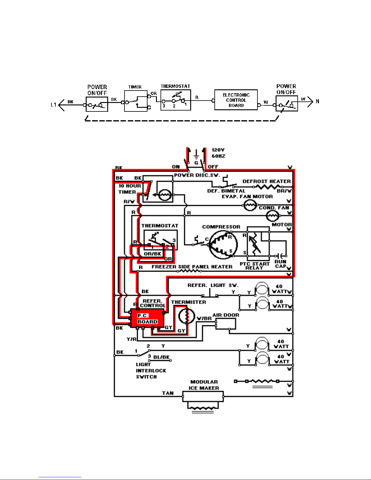
LINE CIRCUITS (# 3)
The Cooling Cycle
3. Freezer Thermostat Turned On And Calling For Cooling –
Compressor On –
Input signal to
Electronic
Control
Board.
WATER VALVE
48
Page 49
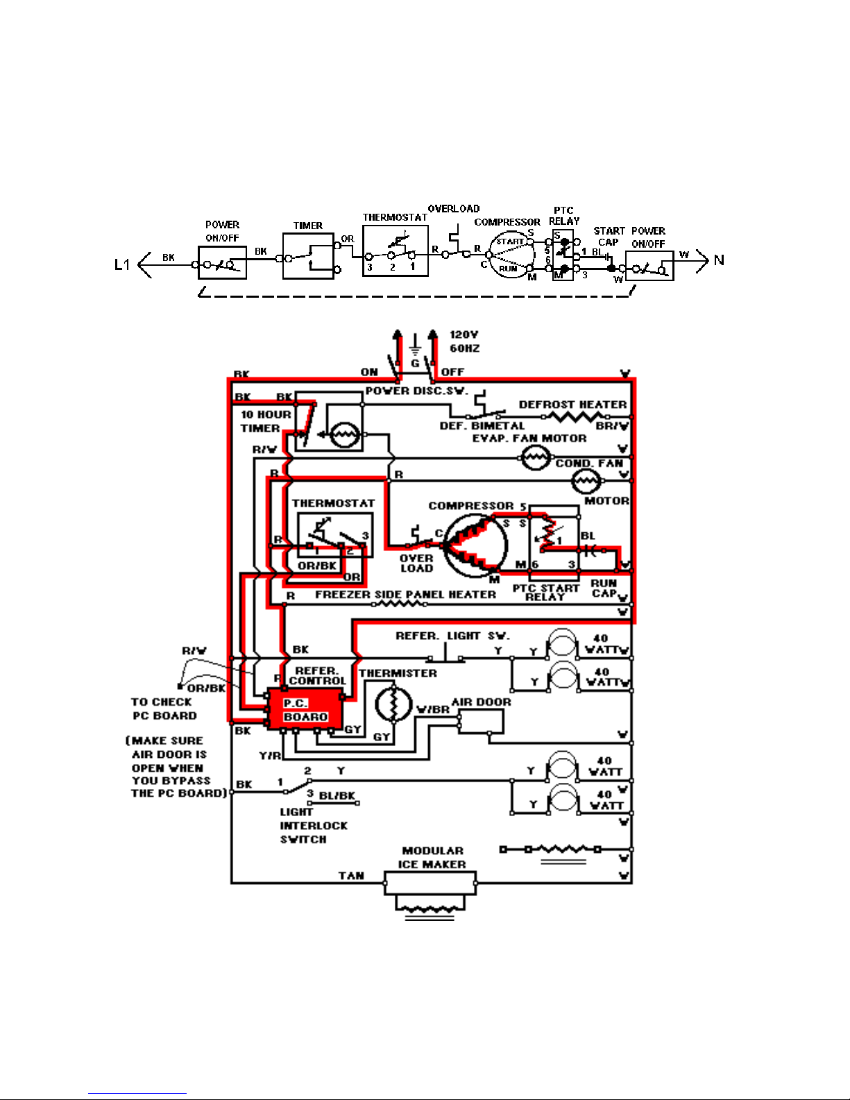
LINE CIRCUITS (# 4)
The Cooling Cycle
4. Freezer Thermostat Calling For Cooling--
Compressor Circuit At Instant Start
WATER VALVE
49
Page 50
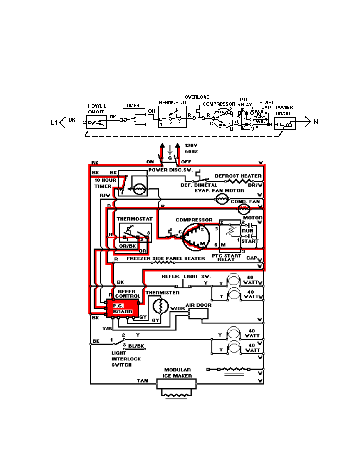
LINE CIRCUIT ( # 5)
The Cooling Cycle
5. Freezer Thermostat Turned On And Calling For Cooling Compressor Circuit
During Run
WATER VALVE
50
Page 51
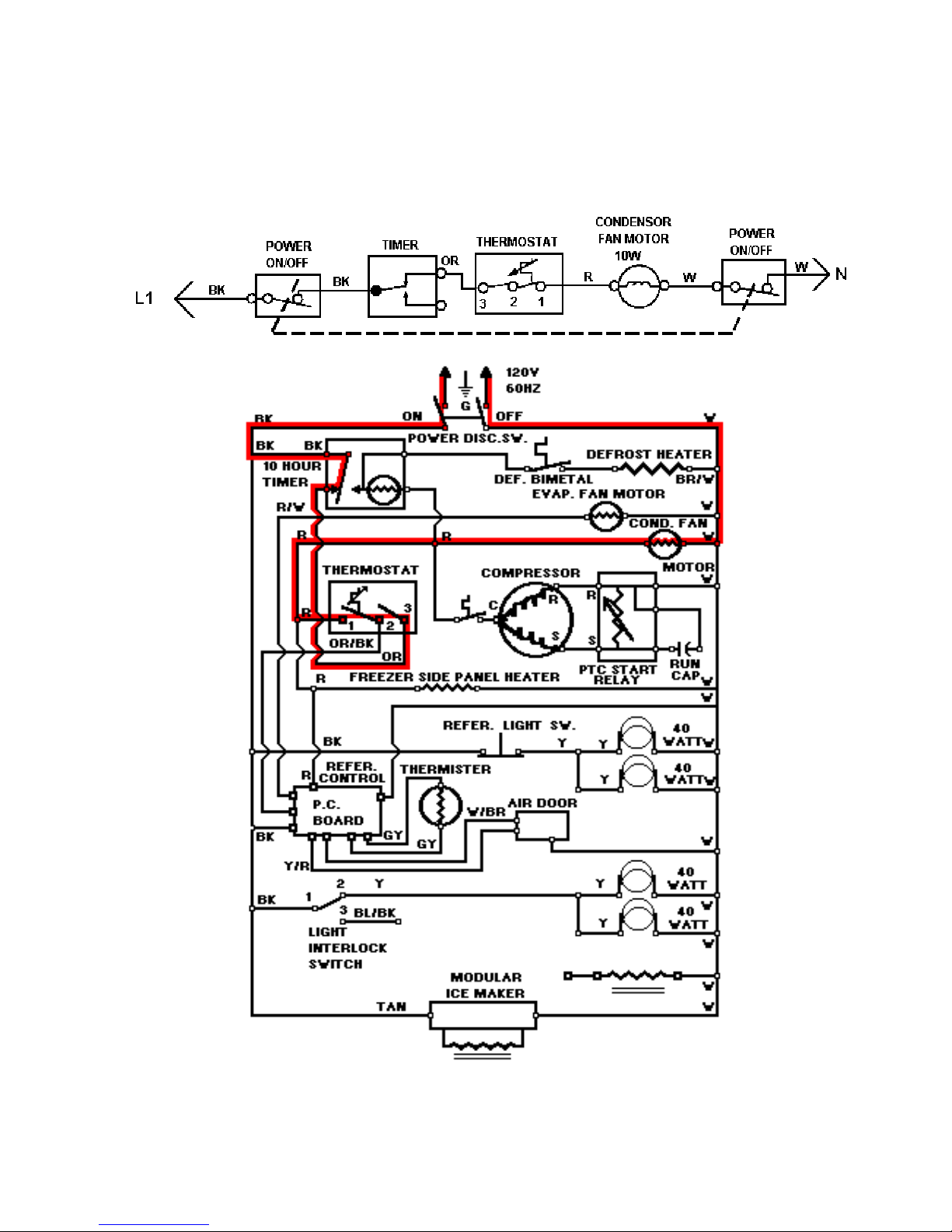
LINE CIRCUITS (# 6)
The Cooling Cycle
6. Freezer Thermostat Calling For Cooling – Condenser Fan Motor Circuit
WATER VALVE
51
Page 52
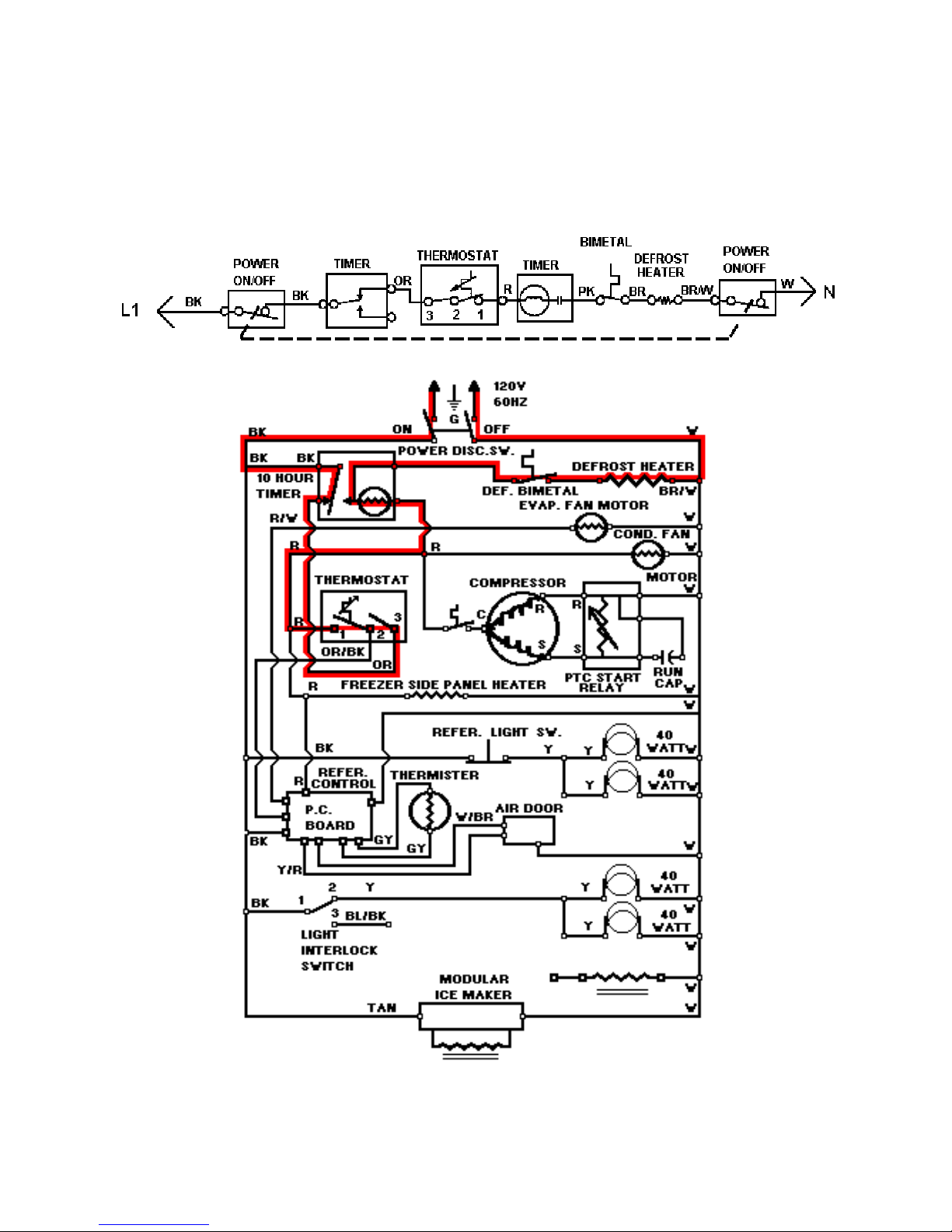
LINE CIRCUITS (# 7)
The Cooling Cycle
7. Freezer Thermostat Turned On And Calling For Cooling -- Defrost Timer Running
WATER VALVE
52
Page 53
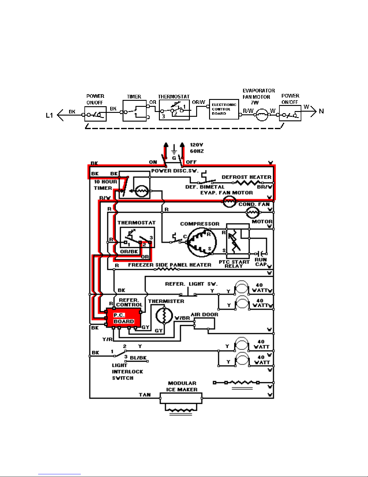
LINE CIRCUITS (# 8)
The Cooling Cycle
8. Freezer Thermostat Turned On And Calling For Cooling -- Evaporator Fan Motor
Circuit
WATER VALVE
53
Page 54
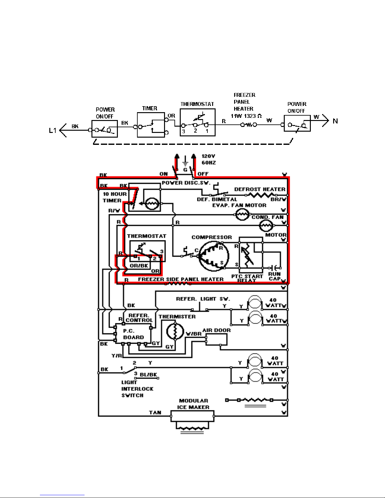
LINE CIRCUITS (# 9)
The Cooling Cycle
9. Freezer Thermostat Calling For Cooling -- Freezer Side Panel Heater Circuit
WATER VALVE
54
Page 55
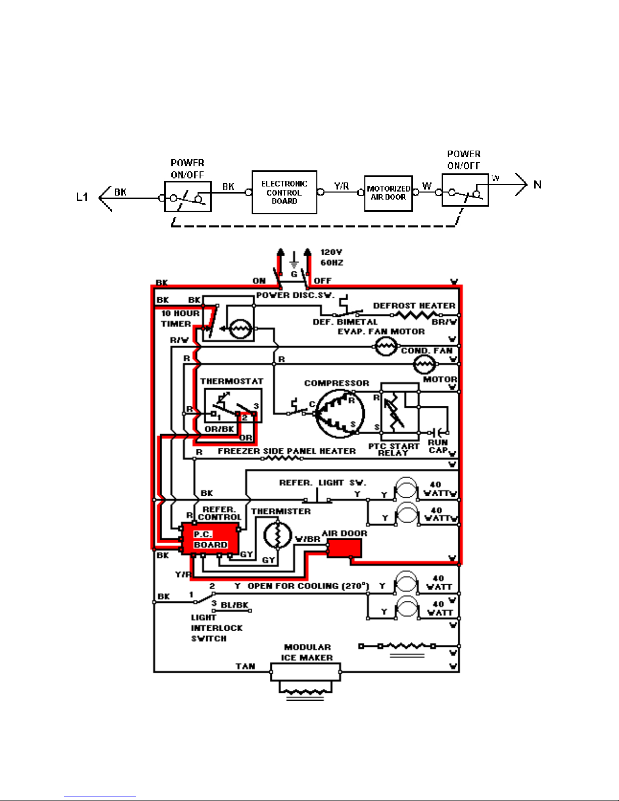
LINE CIRCUITS (# 10)
The Cooling Cycle
10. Refrigerator Control Calling For Cooling -- Motorized Air Door Opening
WATER VALVE
55
Page 56
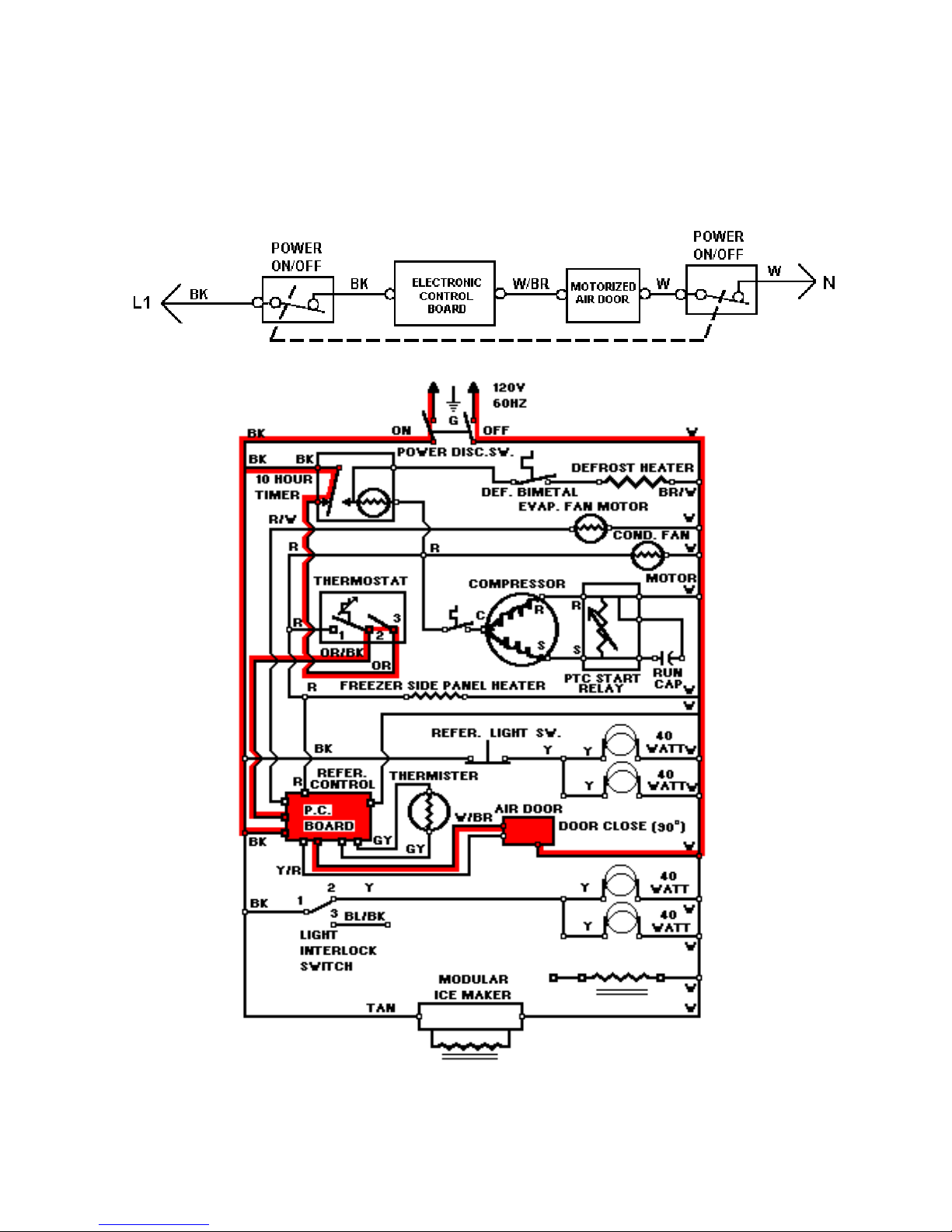
LINE CIRCUITS (# 11)
The Cooling Cycle
11. Refrigerator Control Satisfied -- Motorized Air Door Closing
WATER VALVE
56
Page 57
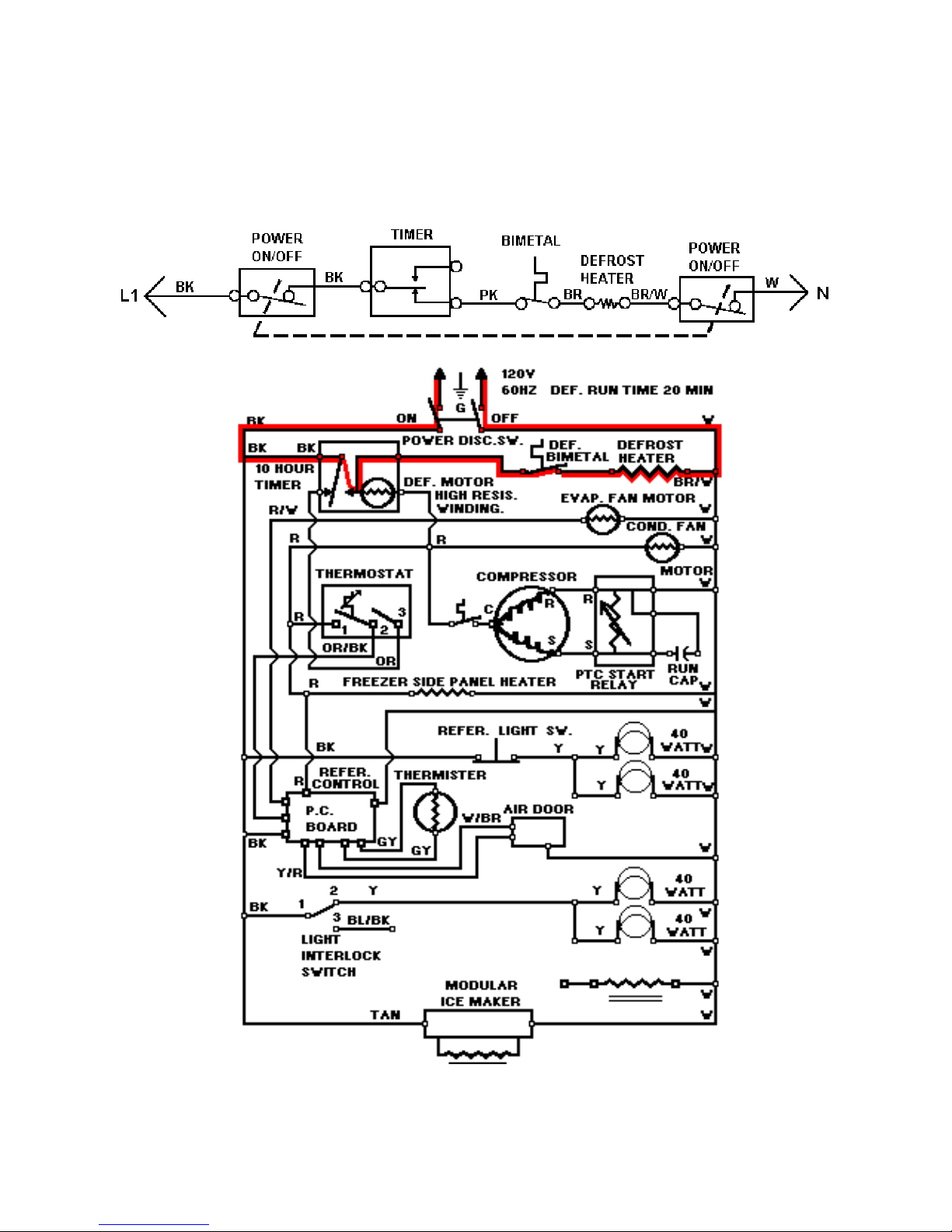
LINE CIRCUITS (# 12)
The Defrost Cycle
12 Defrost Heater Circuit
WATER VALVE
57
Page 58
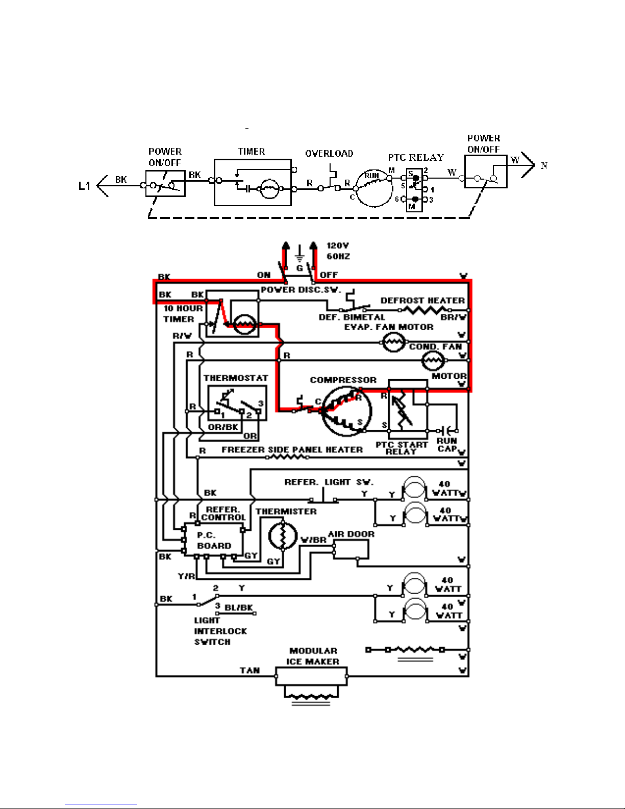
LINE CIRCUITS (# 13)
The Defrost Cycle
13. Defrost Timer Motor Running
WATER VALVE
58
Page 59
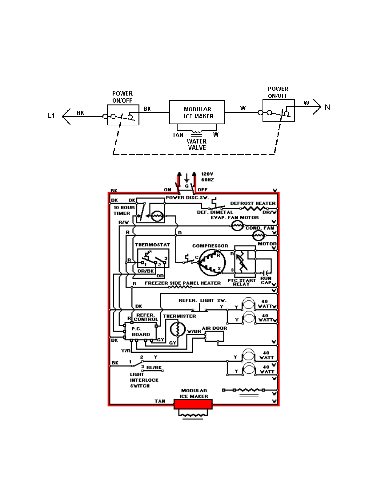
LINE CIRCUITS (#14)
The Dispenser Circuit
14. Modular Ice Maker Circuit
WATER VALVE
59
Page 60
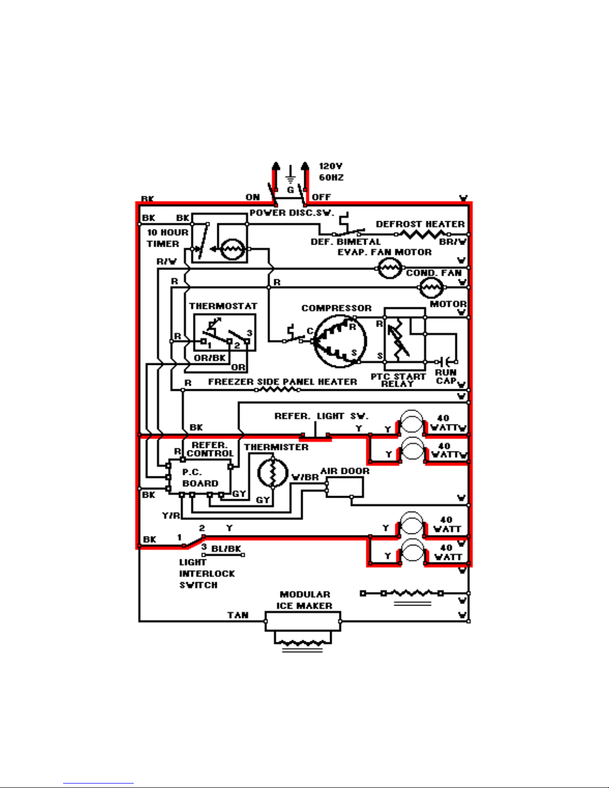
LINE CIRCUITS (#15)
Refrigerator And Freezer Light Circuits
15. Refrigerator And Freezer Light Circuits
WATER VALVE
60
Page 61
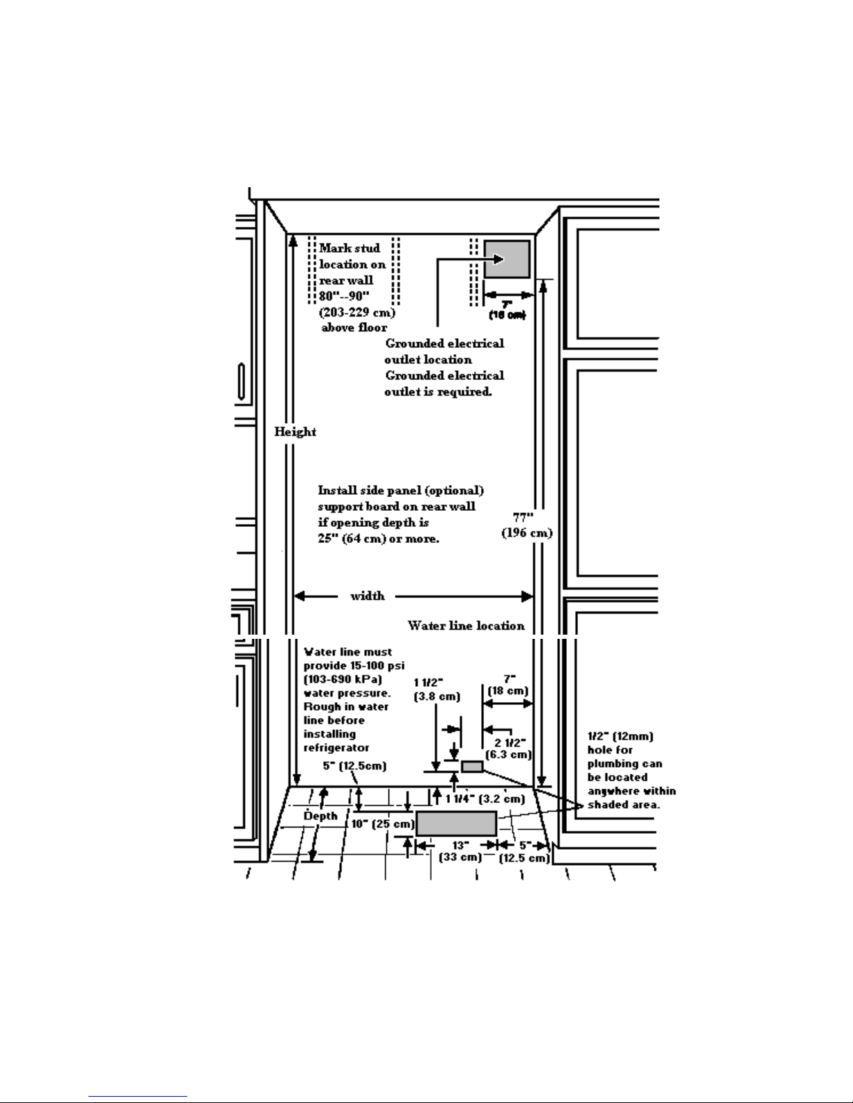
REFRIGERATOR INSTALLATION
61
Page 62
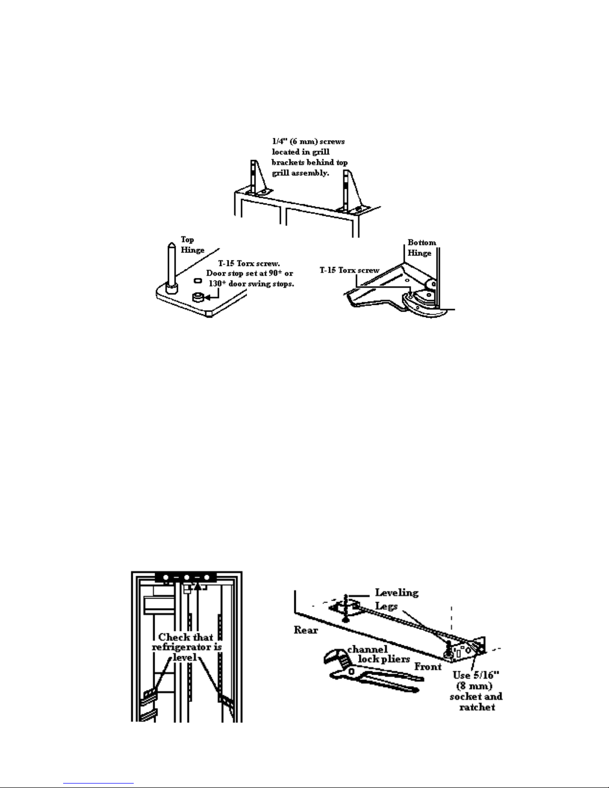
ADJUST DOOR SWING, if needed.
Remove top grill by removing four 1/4" (6 mm) screws located behind the panel assembly. Remove door stop set
screw located in top and bottom hinges using a T-15 Torx wrench. Hold door in the desired position and replace set
screw. If door does not clear countertop after the door stop has been adjusted, countertops may need to be mitered.
LEVEL REFRIGERATOR
by rear legs. Lower front leveling legs with channel lock pliers until weight of the cabinet is supported by
the legs. NOTE: All four legs must contact the floor to support and stabilize the full weight of the
refrigerator.
underside of door trim, on refrigerator product guides, and on freezer basket guides as shown. Adjust front
leveling legs and right and left rear rods until refrigerator is level and at the proper height. Check that all
four leveling legs contact floor and support the full weight of the refrigerator. Doors need to be installed
when leveling.
Right or In or Out, loosen the 3/8” (9mm) hex head screws in the top hinges. If doors need to be
adjusted Up or Down, loosen the 3/8” (9mm) hex screws in the bottom hinges. Adjust doors. Tighten
screws. Check that the doors are aligned and level.
62
Page 63
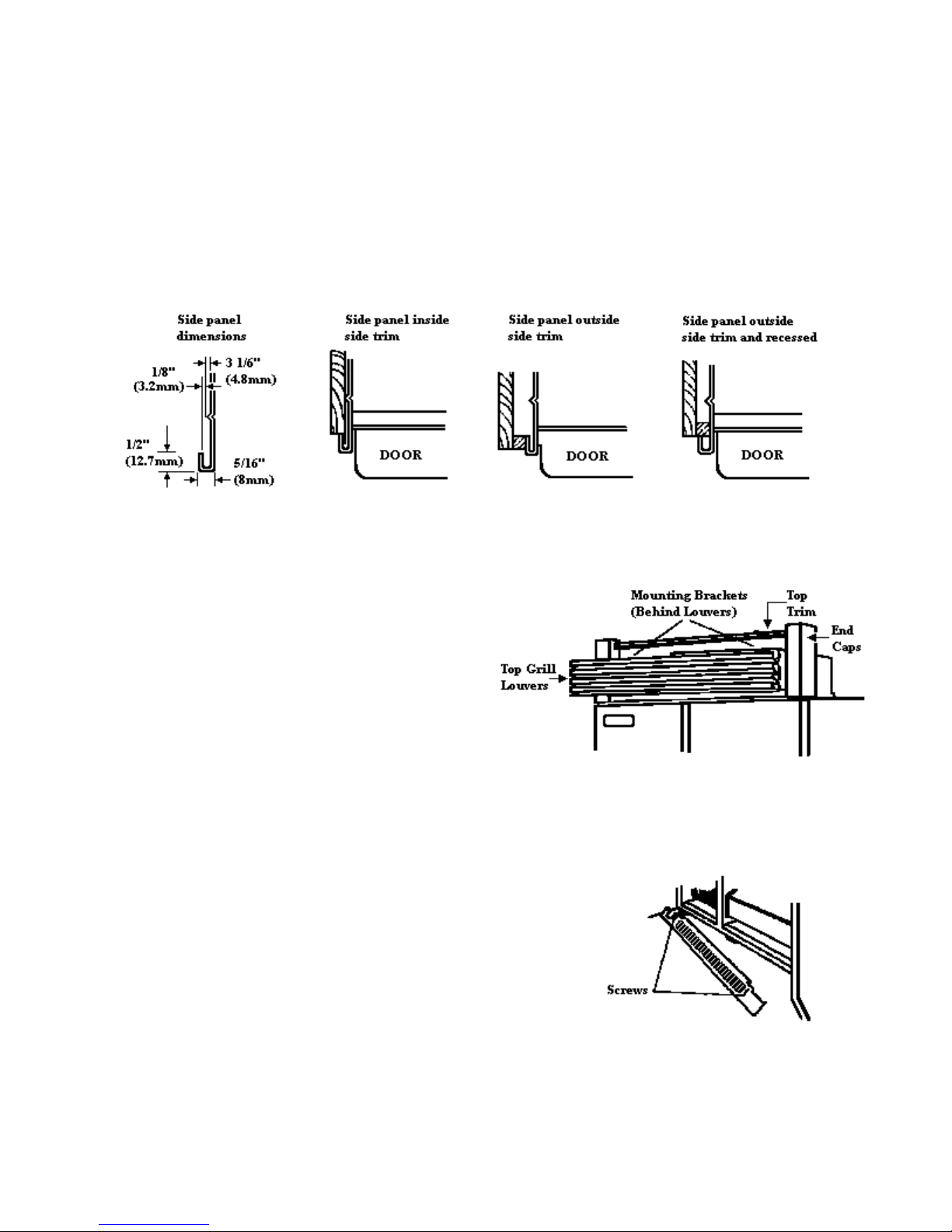
INSTALLING CUSTOM SIDE PANELS
If built-in area depth is 25" (63.5 cm) or more, custom side panels can be installed inside the side trim or attached to
the outside of the side trim. If the side panels will be installed inside the side trim and the panels are more then 1/8"
(3.2 mm) thick, route front edge of panel to fit side trim piece. If panels are less than 1/8" (3.2 mm) thick, install a
filler panel between sides and custom side panels. Follow specific installation instructions provided with custom
INSTALLING TOP GRILL
To remo
INS EIGHT TOP GRILL
ve:
1. Grasp louver area.
2. Push straight up, then pull straight out.
3. s to remove grill assembly
Loosen (4) screw
from unit.
TALL DIFFERENT H
1. Grasp louver area.
2. Push straight up, then pull straight out.
3. s to remove grill assembly
Loosen (4) screw
from unit.
4.
Remove louvers from mounting brackets.
Align new brackets with holes on one end of
louvers. Fasten
at opposite end.
5.
Remove screws attaching top trim to guard.
Readjust trim according to new grill height.
6. ones that correspond
Replace end caps with
with new grill height.
7. Reattach grill assembly.
8. . Pull down
Replace louver assembly
slightly to lock into place.
in place with screws, repeat
63
 Loading...