

Page 1

Viking Installation Guide
Viking Range Corporation
111 Front Street
Greenwood, Mississippi 38930 USA
(662) 455-1200
For product information,
call 1-888-VIKING1 (845-4641)
or visit the Viking Web site at
vikingrange.com
F20115A
(PS032607JJ
Electric Induction Rangetops
)
Page 2
IMPORTANT – Please Read and Follow!
General Information
• Before beginning, please read and follow
these instructions completely and carefully.
• Do not remove permanently affixed labels,
warnings, or plates from product. This may
void the warranty.
• Please observe all local and national codes
and ordinances.
• Please ensure that this product is properly
grounded.
• Installation must conform with local codes,
or in the absence of codes, with the
National Electrical Code, ANSI/NFPA 70,
latest edition.
• In CANADA: Electrical installation must
be in accordance with the current CSA
C22.2 Canadian Electrical Codes Part 1
and/or local codes.
• Installer should leave these instructions
with the consumer who should retain for
local Inspector’s use and for future
reference.
• Consumer should retain this guide for the
local Electrical Inspector’s use.
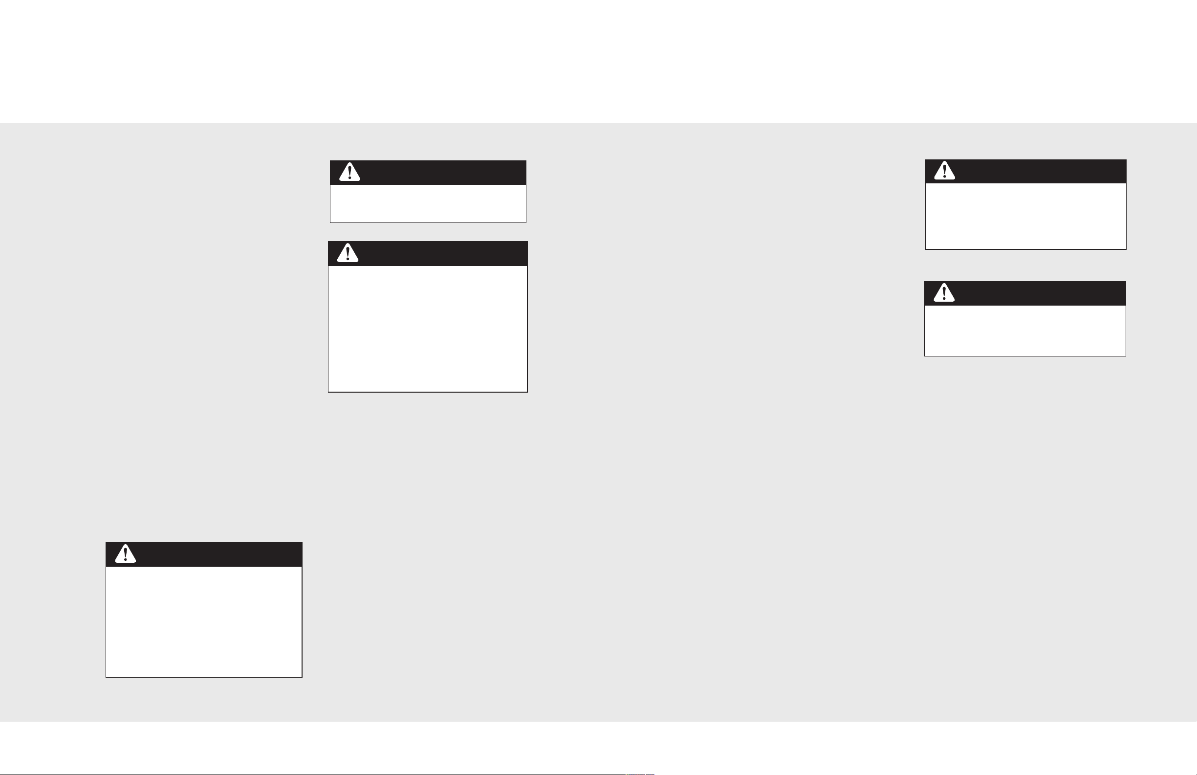
W A R N I N G
The use of cabinets for storage above the
appliance may result in potential fire or burn
hazard. Combustible items may ignite,
metallic items may become hot and cause
burns. If a cabinet storage is to be provided,
the risk can be reduced by installing a
rangehood that projects horizontally a
minimum of 5” (12.7 cm) beyond the bottom
of the cabinets.
W A R N I N G
This appliance should not be used for space
heating. This information is based on safety
considerations.
W A R N I N G
ELECTRICAL GROUNDING
INSTRUCTIONS
This appliance must be electrically in
accordance with local codes, or in the
absence of local codes, the National
Electrical ANSI/NFPA 70, latest edition.
FOR PERSONAL SAFETY, THIS
APPLIANCE MUST BE PROPERLY
GROUNDED.
• All openings in the wall behind the
appliance and/or in the floor under the
appliance should be sealed.
• Keep appliance area clear and free from
combustible materials, gasoline and other
flammable vapors.
• Disconnect the electrical supply prior to
servicing and/or cleaning.
• When removing the appliance for service
and/or cleaning, disconnect AC power
supply and carefully remove the appliance
by pulling forward.
• Electrical requirements are listed in the
product specifications chart. Electrical
installation should comply with national
and local codes.
• DO NOT remove protective packaging
until you are ready to perform the
installation.
Electrical Requirements
Check your national and local codes regarding
this unit. This rangetop is supplied with a 3
wire, 240/208 VAC, 60 Hz conduit which is
equipped with a No. 10 ground wire. See
electrical connection section for grounding
instructions. This unit should be fused
separately.
C A U T I O N
Be sure all electrical power is off between
the breaker box and the junction box, until
the unit is installed and ready to operate.
The junction box should be connected to a
suitable ground.
Electrical Connection
W A R N I N G
Electrical power to the unit must be shut
off while line connections are being made.
Failure to do so could result in serious
injury or death.
When making the wire connections, use the
entire length of the conduit provided (3 feet).
The conduit must not be cut. Connect the red
and black leads from the unit conduit to the
corresponding leads in the junction box. The
bare ground wire in the conduit is connected
to the unit frame. When connecting to a 3conductor branch circuit, if local codes permit,
connect the bare ground connector lead of
the unit to the branch circuit neutral (gray or
white in color).
DDOO NNOOTT UUSSEE AANN EEXXTTEENNSSIIOONN CCOORRDD WWIITTHH
TTHHIISS AAPPPPLLIIAANNCCEE.. SSUUCCHH UUSSEE MMAAYY RREESSUULLTT
IINN AA FFIIRREE,, EELLEECCTTRRIICCAALL SSHHOOCCKK OORR OOTTHHEERR
PPEERRSSOONNAALL IINNJJUURRYY..
Back Trim Accessories
Assembly and installation instructions are
included with all back trim accessories.
1
2
Page 3
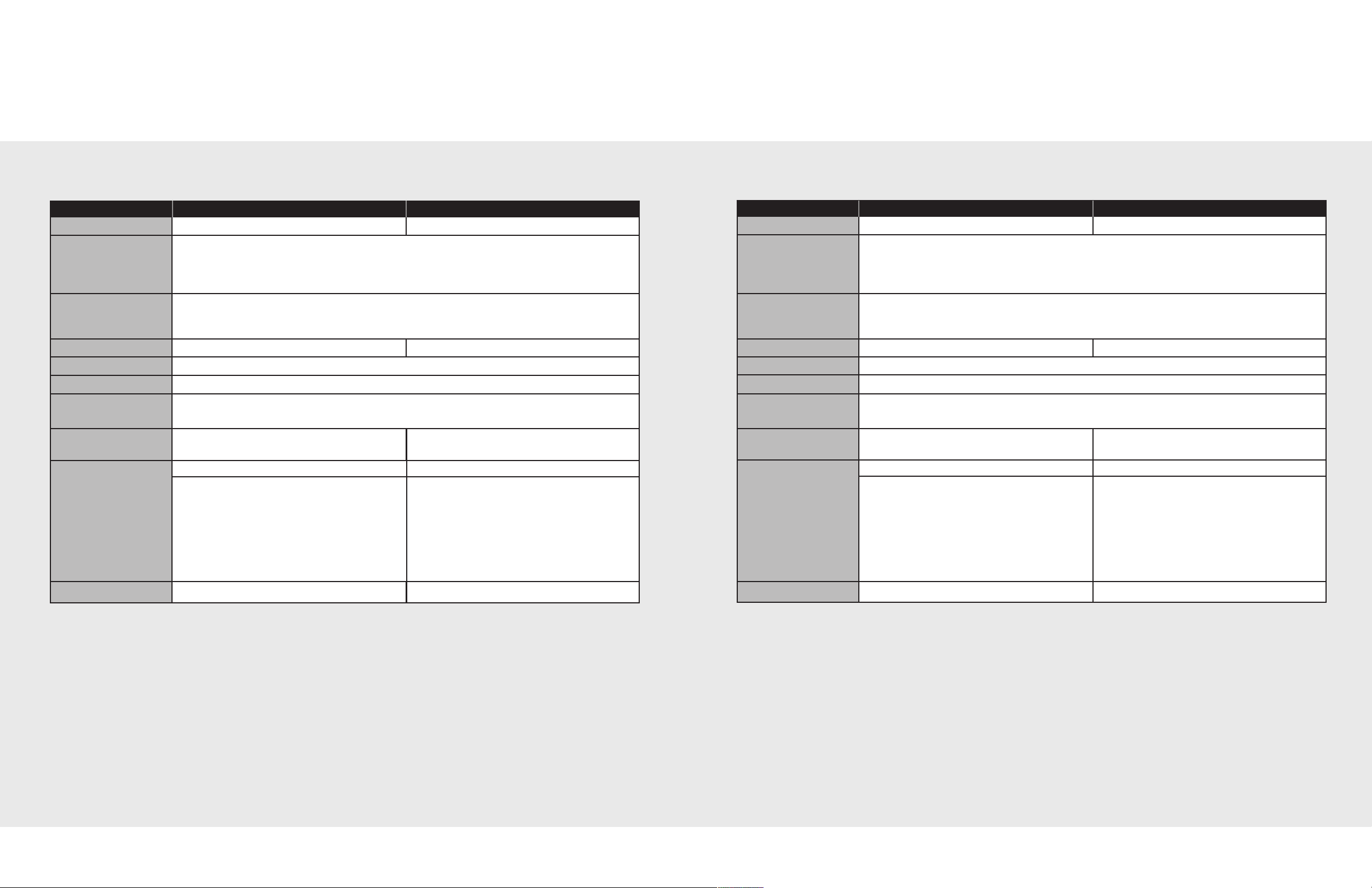
Dimensions & Specifications
Dimensions & Specifications
Induction/Radiant Rangetop
Description VCRT301 VCRT361
Overall Width 29 7/8” (75.9 cm) 35 7/8” (91.1 cm)
Overall Height From
Bottom
Overall Depth From
Rear
Cutout Width 30” (76.2 cm) 36” (91.4 cm)
Cutout Height 7 1/2” (19.1 cm)
Cutout Depth 24” (61.0 cm)
Electrical
Requirements
Maximum Amps
Surface Element
Rating
BASE HEIGHT ADDITIONS TO BASE HEIGHT
To top of glass frame To top of island trim - add 1 1/4” (3.2 cm)
7 7/8” (20.0 cm) To top of backguard - add 6” (15.2 cm)
To top of high-shelf - add 23 1/2” (59.7 cm)
To edge of side panel - 24” (61.0 cm)
To end of control panel - 25 15/16” (65.9 cm)
To end of knobs - 27 7/16” (69.7 cm)
3 - Wire, 240/208 VAC, 60 Hz, electrical connection.
Unit is equipped with No. 10 ground wire in conduit. Should be fused separately.
240v - 37.9 amps
208v - 32.8 amps
240V 208V 240V 208V
Left Front 2500 watts 1875 watts Left Front 2200 watts 1650 watts
Left Rear 1500 watts 1125 watts Left Rear 1500 watts 1125 watts
Right Front 1200 watts 900 watts Right Front 1200 watts 900 watts
Right Rear 3300 watts 2475 watts Right Rear 3300 watts 2475 watts
240v - 55.0 amps
208v - 50.2 amps
Center Front 1800 watts 1350 watts
Bridge 800 watts 600 watts
Center Rear 1800 watts 1350 watts
All Induction Rangetop
Description VIRT301 VIRT361
Overall Width 29 7/8” (75.9 cm) 35 7/8” (91.1 cm)
Overall Height From
Bottom
Overall Depth From
Rear
Cutout Width 30” (76.2 cm) 36” (91.4 cm)
Cutout Height 7 1/2” (19.1 cm)
Cutout Depth 24” (61.0 cm)
Electrical
Requirements
Maximum Amps
Surface Element
Rating
BASE HEIGHT ADDITIONS TO BASE HEIGHT
To top of glass frame To top of island trim - add 1 1/4” (3.2 cm)
7 7/8” (20.0 cm) To top of backguard - add 6” (15.2 cm)
To top of high-shelf - add 23 1/2” (59.7 cm)
To edge of side panel - 24” (61.0 cm)
To end of control panel - 25 15/16” (65.9 cm)
To end of knobs - 27 7/16” (69.7 cm)
3 - Wire, 240/208 VAC, 60 Hz, electrical connection.
Unit is equipped with No. 10 ground wire in conduit. Should be fused separately.
240v - 37.9 amps
208v - 32.8 amps
240V 208V 240V 208V
Left Front 2500 watts 1875 watts Left Front 2700 watts 2025 watts
Left Rear 1500 watts 1125 watts Left Rear 1800 watts 1350 watts
Right Front 1200 watts 900 watts Right Front 1200 watts 900 watts
Right Rear 3300 watts 2475 watts Right Rear 3300 watts 2475 watts
240v - 56.3 amps
208v - 56.3 amps
Center Front 2700 watts 2025 watts
Center Rear 1800 watts 1350 watts
Approx. Shipping Wt.
110 lbs. (49.5 kg) 125 lbs. (56.2 kg)
3
Approx. Shipping Wt.
110 lbs. (49.5 kg) 125 lbs. (56.2 kg)
Minimum Clearance from adjacent combustible construction
• Cooking surfaces and below (36” [91.4 cm] and below)
• Sides - 0”
• Rear - 0” with backguard or highshelf; 0” with island trim and non-combustible wall; 6” (15.2 cm) with
island trim and combustible rear wall
• Top grate support - 36” (91.4 cm)
• Above cooking surface (above 36” [91.4 cm])
• Sides - 6” (15.2 cm)
• Within 6” (15.2 cm) side clearance, wall cabinets no deeper than 13” (33.0 cm) must be minimum 18”
(45.7 cm) above cooking surface.
• Wall cabinets directly above product must be minimum 36” (91.4 cm) above cooking surface.
4
Page 4

Installation
Clearances
Proximity to cabinet installation
1. This rangetop may be installed directly adjacent to existing 36” (91.4 cm) high base cabinets.
2. The rangetop CANNOT be installed directly adjacent to sidewalls, tall cabinets, tall
appliances, or other side vertical surfaces above 36” (91.4 cm) high. There must be a
minimum of 6” (15.2 cm) side clearance from the rangetop to such combustible surfaces
above the 36” (91.4 cm) counter height.
3. Within the 6” (15.2 cm) side clearance to combustible vertical surfaces above 36” (91.4 cm),
the maximum wall cabinet depth must be 13” (33.0 cm) and wall cabinets within this 6” (15.2
cm) side clearance must be 18” (45.7 cm) above the 36” (91.4 cm) high countertop.
4. Wall cabinets above the rangetop must be a minimum of 36” (91.4 cm) above the rangetop
cooking surface for the full width of the rangetop.
SSIIDDEE FFRROONNTT
Interior Cabinet Clearances for proper airflow
Detailed View of Bottom Support
2 3/4”
(7.0 cm)
1 1/2” dia.
cutout for
conduit
1 1/2”
(3.8 cm)
Remove the material from this area
for proper air flow into the unit.
3” (7.6 cm)
2”
(5.1 cm)
8” (20.3 cm)
8” (20.3 cm)
3” (7.6 cm)
7 1/2”
(19.1 cm)
36” Min.
(91.4 cm)
13” Max
(33.0 cm)
6” Min.
(15.2 cm)
36” Min.
(91.4 cm)
18” Min.
(45.7 cm)
IIMMPPOORRTTAANNTT::
induction elements in the rangetop need some air
circulation. To ensure long life of electronic
components, it is required that a minimum of 8”
(20.3 cm) of open space remain between the
bottom of the unit and any shelf underneath. The
maximum length of the shelf underneath is to be
18” (45.7 cm) There should be no partition or shelf
ddiirreeccttllyy
underneath the unit.
The electronic components for the
8” Min.
(20.3 cm)
18” Max.
(45.7 cm)
5
6
Page 5

Final Preparation
1. The interior of the oven should be washed
thoroughly with hot, soapy water to
remove film residues and installation
debris before being used for food
preparation, then rinsed and wiped dry.
Solutions stronger than soapy water are
rarely needed.
2. Some stainless steel parts may have a
plastic protective wrap, which must be
removed. All stainless steel body parts
should be washed with hot soapy water
and with liquid cleaner designed for this
material. If build-up occurs, do not use
steel wool, abrasive cloths, cleaners or
powders! If it is necessary to scrape
stainless steel to remove encrusted
materials, soak with hot, wet cloths to
loosen the material, then use a wood or
nylon scraper. Do not use a metal knife,
spatula, or any other metal tool to scrape
stainless steel!! Scratches are almost
impossible to remove.
Service & Parts
Only authorized replacement parts may be
used in performing service on the appliance.
Do not repair or replace any part of the
appliance unless specifically recommended
in the manual. All other servicing should be
referred to a qualified technician.
Record the following information indicated
below. You will need it if service is ever
required. The serial number and model number
for your appliance are located on the
identification plate mounted on the inside of
the water tank opening.
Model number
_________________________________________
Serial number
_________________________________________
Date of purchase
_________________________________________
Date installed
_________________________________________
Dealer's name
_________________________________________
Address
_________________________________________
These installation instructions should remain
with the unit for future reference.
Contact Viking Range Corporation, (888)
845-4641, for the nearest service parts
distributor in your area.
87
Page 6

Electric All Induction 30” Wide
P
OWER BOARD
J
OUT1
J
OUT2
SMALL COIL
J
3
TEMP CONTROL
J14
J15
J11
J10
LED
BOARD
FRONT
REAR
LARGE COIL
JOUT3
JOUT4
J2
J12
J13
TEMP CONTROL
RED
BLACK
RED
BLACK
AC
FAN
J16
J17
J6
J7
J4
J5
J18
J19
JE5
JE6
JE4JE3
JE8JE7
JE1
JE2
EMI BOARD
LEFT
SMALL COIL
P
OTENTIOMETER
LARGE COIL
POTENTIOMETER
J9
J8
RED
B
LACK
BLACK
RED
VIO
GRAY
SECTION
B
LUE
WHITE
POWER LINE
CONDITIONER
J
1
L1C L2R
L2
L1
R
ED
BLACK
GREEN
CHASSIS GROUND
J
2
L1R
L
2C
J
4J3
POWER BOARD
JOUT1
JOUT2
S
MALL COIL
J3
T
EMP CONTROL
J14
J
15
J11
J10
LED
BOARD
FRONT
R
EAR
LARGE COIL
JOUT3
JOUT4
J2
J12
J13
TEMP CONTROL
RED
BLACK
RED
BLACK
A
C
FAN
J
16
J17
J6
J
7
J4
J5
J18
J19
JE5
JE6
JE4JE3
JE8JE7
JE1
JE2
EMI BOARD
RIGHT
SMALL COIL
POTENTIOMETER
LARGE COIL
POTENTIOMETER
J9
J8
RED
BLACK
BLACK
RED
VIO
GRAY
SECTION
BROWN
O
RG
Rangetop Wiring Diagram
This unit must be properly grounded. See
W A R N I N G
installation instructions for proper grounding
instructions. NOTE: Trailers or stripes will be
the second color in a color combination.
C A U T I O N
Label all wires prior to disconnection when
servicing controls. Wiring errors can cause
improper and dangerous operation. Verify
proper operation after servicing.
109
Page 7

Electric Induction/Radiant 30” Wide
2500/1000 WAT T
L. F. ELEM.
1500 WATT
L.R. ELEM.
RED/YEL
BLK/WH
BLK
YEL/BLK
WH/BLK
BLK
RED
RED/BLK
YEL/RED
WH/RED
RED/BLK
ORG
YEL/RED
YEL/BLK
WH/BLK
RED
WH/RED
RED/BLK
RED/BLK
RED/BLK
RED
ORG
ORG
POWER BOARD
AC
FAN
J16
J17
J6
J7
J4
J
5
J18
J19
POWER LINE
CONDITIONER
J1
L1C L2R
ORG
BROWN
J2
L1RL2C
J4 J3
JOUT1
JOUT2
S
MALL COIL
J3
TEMP CONTROL
J14
J15
J11
J10
LED
B
OARD
FRONT
REAR
LARGE COIL
JOUT3
JOUT4
J2
J12
J
13
TEMP CONTROL
SMALL COIL
POTENTIOMETER
LARGE COIL
POTENTIOMETER
J9
J8
JE5
J
E6
JE4JE3
J
E8JE7
J
E1
JE2
EMI BOARD
RED
BLACK
BLACK
RED
VIO
GRAY
BLACK
RED
L2
L1
SURF. ELEM.
POWER ON
LIGHT
BLACK
RED
L
P
1
H1
H2
L
2
RED
RED/BLK
RED
RED/BLK
PURPLE
PURPLE
RED
(H1)a
(H2)
(H1)b
P
L2
L
1
RED
PURPLE
ORG
RED
RED
BLACK
WHITE
Y
ELLOW
GREEN
CHASSIS GROUND
Rangetop Wiring Diagram
W A R N I N G
This unit must be properly grounded. See
installation instructions for proper grounding
instructions. NOTE: Trailers or stripes will be
the second color in a color combination.
C A U T I O N
Label all wires prior to disconnection when
servicing controls. Wiring errors can cause
improper and dangerous operation. Verify
proper operation after servicing.
1211
Page 8

Electric All Induction 36” Wide
POWER BOARD
J
OUT1
J
OUT2
S
MALL COIL
J3
TEMP CONTROL
J
14
J
15
J11
J
10
LED
BOARD
F
RONT
REAR
LARGE COIL
JOUT3
JOUT4
J2
J
12
J13
TEMP CONTROL
W
HITE
YELLOW
RED
BLACK
AC
F
AN
J16
J
17
J
6
J
7
J
4
J
5
J18
J19
J
E5
J
E6
JE4JE3
JE8JE7
J
E1
JE2
EMI BOARD
P
OWER BOARD
JOUT1
JOUT2
S
MALL COIL
J
3
T
EMP CONTROL
J14
J
15
SMALL COIL
P
OTENTIOMETER
L
ED
BOARD
F
RONT
R
EAR
LARGE COIL
LARGE COIL
P
OTENTIOMETER
JOUT3
JOUT4
J2
J
12
J13
TEMP CONTROL
RED
BLACK
W
HITE
YELLOW
AC
FAN
J
16
J
17
J6
J7
J4
J
5
J18
J19
JE5
J
E6
JE4JE3
JE8JE7
JE1
JE2
EMI BOARD
RIGHT
CENTER
BLUE
WHITE
O
RG
B
ROWN
S
MALL COIL
POTENTIOMETER
LARGE COIL
P
OTENTIOMETER
SECTION
J9
J8
J9
J8
J
11
J
10
RED
RED
VIO
BLACK
BLACK
GRAY
R
ED
BLACK
BLACK
RED
VIO
GRAY
POWER LINE
CONDITIONER
J
1
L
1C
L2R
L2
L1
RED
B
LACK
GREEN
CHASSIS GROUND
J
2
L
1R
L2C
J4 J3
J6 J5
L1L
L
2L
POWER BOARD
JOUT1
J
OUT2
SMALL COIL
J
3
TEMP CONTROL
J
14
J
15
J11
J10
LED
BOARD
FRONT
REAR
LARGE COIL
JOUT3
JOUT4
J2
J
12
J
13
TEMP CONTROL
W
HITE
YELLOW
RED
BLACK
AC
F
AN
J16
J17
J
6
J
7
J
4
J
5
J18
J19
J
E5
J
E6
J
E4JE3
J
E8JE7
JE1
J
E2
EMI BOARD
LEFT
SMALL COIL
P
OTENTIOMETER
LARGE COIL
POTENTIOMETER
J9
J
8
RED
B
LACK
BLACK
RED
VIO
GRAY
SECTION
SECTION
YELLOW
WHT/RED
(FRONT)
(REAR)
(REAR)
(FRONT)
(
FRONT)
(REAR)
Rangetop Wiring Diagram
W A R N I N G
This unit must be properly grounded. See
installation instructions for proper grounding
instructions. NOTE: Trailers or stripes will be
the second color in a color combination.
13
C A U T I O N
Label all wires prior to disconnection when
servicing controls. Wiring errors can cause
improper and dangerous operation. Verify
proper operation after servicing.
14
Page 9

Electric Induction/Radiant 36” Wide
2200/1000 WAT T
L. F. ELEM.
1500 WAT T
L
.R. ELEM.
RED/YEL
BLK/WH
BLK
YEL/BLK
WH/BLK
BLK
RED
RED/BLK
Y
EL/RED
WH/RED
RED/BLK
ORG
L2
L1
SURF. ELEM.
POWER ON
LIGHT
BLACK
RED
L
P
1
H
1
H2
L
2
RED
RED/BLK
YEL/RED
YEL/BLK
WH/BLK
RED
WH/RED
R
ED
RED/BLK
RED/BLK
RED/BLK
RED/BLK
RED
PURPLE
PURPLE
RED
(H1)a
(H2)
(H1)b
P
L2
L1
RED
ORG
ORG
L
P
1
H1
H2
L
2
RED
RED/BLK
RED
RED/BLK
(H1)a
(H2)
(H1)b
P
L2
L1
PURPLE
RED
B
LK
WH/RED
RED/BLK
YEL/RED
RED/BLK
ORG
WH/BLK
RED/YEL
BLK/WHT
YEL/BLK
ORG
YEL/RED
WH/RED
MIDDLE
FRONT
L
EFT
REAR
MIDDLE
REAR
L
EFT
FRONT
B
RIDGE ELEM
1800 WAT T
800 WAT T
1800 WAT T
POWER BOARD
AC
FAN
J16
J17
J6
J7
J4
J5
J18
J19
POWER LINE
CONDITIONER
J
1
L1C
L2R
GREEN
CHASSIS GROUND
ORG
BROWN
J
2
L1R
L2C
J4 J3
JOUT1
JOUT2
SMALL COIL
J3
TEMP CONTROL
J14
J15
J11
J10
LED
BOARD
FRONT
REAR
LARGE COIL
JOUT3
JOUT4
J2
J12
J13
TEMP CONTROL
RED
BLACK
WHITE
YELLOW
S
MALL COIL
POTENTIOMETER
LARGE COIL
POTENTIOMETER
J9
J8
JE5
JE6
JE4JE3
J
E8JE7
JE1
JE2
EMI BOARD
RED
BLACK
BLACK
R
ED
VIO
GRAY
BLACK
RED
RED
(FRONT)
(REAR)
Rangetop Wiring Diagram
This unit must be properly grounded. See
installation instructions for proper grounding
W A R N I N G
instructions. NOTE: Trailers or stripes will be
the second color in a color combination.
C A U T I O N
Label all wires prior to disconnection when
servicing controls. Wiring errors can cause
improper and dangerous operation. Verify
proper operation after servicing.
1615
 Loading...